EP3668280A1 - Réacteur à plasma non thermique allongé pour un couplage optimal à une alimentation pulsée - Google Patents
Réacteur à plasma non thermique allongé pour un couplage optimal à une alimentation pulsée Download PDFInfo
- Publication number
- EP3668280A1 EP3668280A1 EP18212650.8A EP18212650A EP3668280A1 EP 3668280 A1 EP3668280 A1 EP 3668280A1 EP 18212650 A EP18212650 A EP 18212650A EP 3668280 A1 EP3668280 A1 EP 3668280A1
- Authority
- EP
- European Patent Office
- Prior art keywords
- plasma reactor
- modules
- reactor
- length
- plasma
- Prior art date
- Legal status (The legal status is an assumption and is not a legal conclusion. Google has not performed a legal analysis and makes no representation as to the accuracy of the status listed.)
- Withdrawn
Links
- 230000008878 coupling Effects 0.000 title description 3
- 238000010168 coupling process Methods 0.000 title description 3
- 238000005859 coupling reaction Methods 0.000 title description 3
- 230000004888 barrier function Effects 0.000 claims abstract description 14
- 230000005540 biological transmission Effects 0.000 claims abstract description 9
- 238000006243 chemical reaction Methods 0.000 claims description 15
- 239000012530 fluid Substances 0.000 claims description 11
- 230000007704 transition Effects 0.000 claims description 9
- 238000012545 processing Methods 0.000 claims description 4
- 239000007789 gas Substances 0.000 description 35
- MWUXSHHQAYIFBG-UHFFFAOYSA-N nitrogen oxide Inorganic materials O=[N] MWUXSHHQAYIFBG-UHFFFAOYSA-N 0.000 description 10
- IJGRMHOSHXDMSA-UHFFFAOYSA-N Atomic nitrogen Chemical compound N#N IJGRMHOSHXDMSA-UHFFFAOYSA-N 0.000 description 8
- 230000008859 change Effects 0.000 description 6
- CBENFWSGALASAD-UHFFFAOYSA-N Ozone Chemical compound [O-][O+]=O CBENFWSGALASAD-UHFFFAOYSA-N 0.000 description 5
- 230000008901 benefit Effects 0.000 description 5
- XLYOFNOQVPJJNP-UHFFFAOYSA-N water Substances O XLYOFNOQVPJJNP-UHFFFAOYSA-N 0.000 description 5
- QVGXLLKOCUKJST-UHFFFAOYSA-N atomic oxygen Chemical compound [O] QVGXLLKOCUKJST-UHFFFAOYSA-N 0.000 description 4
- 238000013461 design Methods 0.000 description 4
- 229910052757 nitrogen Inorganic materials 0.000 description 4
- 239000001301 oxygen Substances 0.000 description 4
- 229910052760 oxygen Inorganic materials 0.000 description 4
- 238000013459 approach Methods 0.000 description 3
- 238000004519 manufacturing process Methods 0.000 description 3
- 238000000034 method Methods 0.000 description 3
- 230000001902 propagating effect Effects 0.000 description 3
- 239000003990 capacitor Substances 0.000 description 2
- 239000013626 chemical specie Substances 0.000 description 2
- 238000001816 cooling Methods 0.000 description 2
- 230000001419 dependent effect Effects 0.000 description 2
- 238000011161 development Methods 0.000 description 2
- 239000003989 dielectric material Substances 0.000 description 2
- 239000000126 substance Substances 0.000 description 2
- 230000001052 transient effect Effects 0.000 description 2
- 230000003115 biocidal effect Effects 0.000 description 1
- 239000003139 biocide Substances 0.000 description 1
- 238000004140 cleaning Methods 0.000 description 1
- 230000006835 compression Effects 0.000 description 1
- 238000007906 compression Methods 0.000 description 1
- 230000000593 degrading effect Effects 0.000 description 1
- 230000000249 desinfective effect Effects 0.000 description 1
- 238000006073 displacement reaction Methods 0.000 description 1
- 238000005265 energy consumption Methods 0.000 description 1
- 230000007613 environmental effect Effects 0.000 description 1
- 238000001125 extrusion Methods 0.000 description 1
- 230000002349 favourable effect Effects 0.000 description 1
- 230000004907 flux Effects 0.000 description 1
- 238000011065 in-situ storage Methods 0.000 description 1
- 239000007788 liquid Substances 0.000 description 1
- 239000000463 material Substances 0.000 description 1
- 238000012986 modification Methods 0.000 description 1
- 230000004048 modification Effects 0.000 description 1
- 230000035699 permeability Effects 0.000 description 1
- 229920000642 polymer Polymers 0.000 description 1
- 238000004659 sterilization and disinfection Methods 0.000 description 1
- 238000004381 surface treatment Methods 0.000 description 1
- 238000012546 transfer Methods 0.000 description 1
Images


Classifications
-
- H—ELECTRICITY
- H05—ELECTRIC TECHNIQUES NOT OTHERWISE PROVIDED FOR
- H05H—PLASMA TECHNIQUE; PRODUCTION OF ACCELERATED ELECTRICALLY-CHARGED PARTICLES OR OF NEUTRONS; PRODUCTION OR ACCELERATION OF NEUTRAL MOLECULAR OR ATOMIC BEAMS
- H05H1/00—Generating plasma; Handling plasma
- H05H1/24—Generating plasma
- H05H1/2406—Generating plasma using dielectric barrier discharges, i.e. with a dielectric interposed between the electrodes
- H05H1/2418—Generating plasma using dielectric barrier discharges, i.e. with a dielectric interposed between the electrodes the electrodes being embedded in the dielectric
-
- H—ELECTRICITY
- H05—ELECTRIC TECHNIQUES NOT OTHERWISE PROVIDED FOR
- H05H—PLASMA TECHNIQUE; PRODUCTION OF ACCELERATED ELECTRICALLY-CHARGED PARTICLES OR OF NEUTRONS; PRODUCTION OR ACCELERATION OF NEUTRAL MOLECULAR OR ATOMIC BEAMS
- H05H1/00—Generating plasma; Handling plasma
- H05H1/02—Arrangements for confining plasma by electric or magnetic fields; Arrangements for heating plasma
- H05H1/03—Arrangements for confining plasma by electric or magnetic fields; Arrangements for heating plasma using electrostatic fields
-
- H—ELECTRICITY
- H05—ELECTRIC TECHNIQUES NOT OTHERWISE PROVIDED FOR
- H05H—PLASMA TECHNIQUE; PRODUCTION OF ACCELERATED ELECTRICALLY-CHARGED PARTICLES OR OF NEUTRONS; PRODUCTION OR ACCELERATION OF NEUTRAL MOLECULAR OR ATOMIC BEAMS
- H05H1/00—Generating plasma; Handling plasma
- H05H1/24—Generating plasma
- H05H1/2406—Generating plasma using dielectric barrier discharges, i.e. with a dielectric interposed between the electrodes
-
- H—ELECTRICITY
- H05—ELECTRIC TECHNIQUES NOT OTHERWISE PROVIDED FOR
- H05H—PLASMA TECHNIQUE; PRODUCTION OF ACCELERATED ELECTRICALLY-CHARGED PARTICLES OR OF NEUTRONS; PRODUCTION OR ACCELERATION OF NEUTRAL MOLECULAR OR ATOMIC BEAMS
- H05H1/00—Generating plasma; Handling plasma
- H05H1/24—Generating plasma
- H05H1/46—Generating plasma using applied electromagnetic fields, e.g. high frequency or microwave energy
- H05H1/461—Microwave discharges
- H05H1/4622—Microwave discharges using waveguides
-
- H—ELECTRICITY
- H05—ELECTRIC TECHNIQUES NOT OTHERWISE PROVIDED FOR
- H05H—PLASMA TECHNIQUE; PRODUCTION OF ACCELERATED ELECTRICALLY-CHARGED PARTICLES OR OF NEUTRONS; PRODUCTION OR ACCELERATION OF NEUTRAL MOLECULAR OR ATOMIC BEAMS
- H05H2242/00—Auxiliary systems
- H05H2242/20—Power circuits
- H05H2242/26—Matching networks
Definitions
- Embodiments of the present disclosure generally relate to generation of plasma with the method of dielectric barrier discharge.
- the current disclosure provides a scalable plasma reactor for a dielectric barrier discharge, using non-thermal plasma, with a propagating dielectric barrier discharge region to couple it to a pulsed power supply in an optimized way.
- Dielectric barrier discharges are frequently used in industrial applications for the generation of chemical species, like chemical radicals, that can be used, among others, for disinfection and cleaning of surfaces or liquids.
- Dielectric barrier discharges have e.g. been applied as source for reactive chemical species for the treatment of ballast water.
- DBD reactors e.g., for the production of ozone
- DBD reactors may be operated at high voltages in the range of 1 kV to 100 kV.
- a slow sinusoidal ac waveform commonly used for commercial applications, with frequencies between 10 Hz and 10,000 Hz and a pulse train shaped waveform consisting of short, preferably rectangular shaped voltage pulses with a fast rise-time ( ⁇ 100 ns).
- the present applications therefore provides a way to overcome this limitation and seeks to provide an efficient way to operate a large DBD reactor with high-voltage pulse supplies with fast rise-times to avoid losses of energy caused by reflections.
- a plasma reactor for a Dielectric Barrier Discharge (DBD) system is disclosed.
- the plasma reactor may comprise one or more plasma reactor modules, wherein the one or more plasma modules are configured as transmission lines.
- a duration of a rise-time and/or a fall-time of a voltage pulse, fed into a first end of the one or more reactor modules is shorter than a run-time of the voltage pulse from a first end of the one or more reactor modules to a second end of the one or more reactor modules.
- a dielectric barrier discharge DBD requires an electrode pair, preferably separated by a dielectric material and a discharge gap.
- the discharge gap may be arranged between the electrodes.
- the gap may be partially filled with the dielectric material.
- the dielectric may be also a dielectric layer on one of the electrodes.
- the dielectric layer material may also be arranged on both electrodes. r may be arranged on. In a classical design, these electrodes may be designed as pure capacitors. Transient effects of the voltage pulse traveling along the electrode may not play a crucial role in such an arrangement.
- the reactor may have an electrode design that which is "elongated". That means, the electrodes substantially extend in the direction of the propagation of the electrical pulse
- the reactor is only characterized by its impedance (which can be adapted by changing the cross section geometry), and not by the total capacity
- an electrical system power for operating a plasma reactor according to the present application should preferably be designed for a characteristic wave impedance of the reactor for a dielectric barrier discharge.
- the present application may allow to operate a DBD reactor, in particular a large-scale scale DBD reactor, with a pulsed voltage waveform that is characterized by short rise- and fall times of less than 100 ns.
- the conversion of electrical energy into active species may be more efficient for a pulsed operation of the reactor, compared to an operation with a slow ac voltage.
- the presented layout of the reactor geometry may be easily scaled to different sizes of plasma reactors, e.g. by simply changing the length of the reactor, to generate a predetermined amount of active species required by the respective application.
- a geometry of the DBD reactor may be chosen in a way that a length in one direction is comparable with the physical length of the voltage pulse. That means, in case the length of the voltage pulse is physically 2 m for example, the DBD reactor may also have a length of 2 m. Other relations of pulse lengths and reactor lengths are possible. A pulse length can e.g. also be two times the reactor length.
- a specific diameter or cross-section of the DBD reactor may be also be determined accordingly.
- a larger diameter or cross-section influences an amount of treatable gas and also the characteristic impedance.
- a plasma reactor for a Dielectric Barrier Discharge (DBD) system may comprise one or more plasma reactor modules, wherein the one or more plasma modules are configured as transmission lines. That means, the modules have a characteristic impedance. Further, a duration of a rise-time and/or a fall-time of a voltage pulse, fed into a first end of the one or more reactor modules is shorter than a run-time of the voltage pulse from a first end of the one or more reactor modules to a second end of the one or more reactor modules.
- the plasma reactor modules in the disclosed plasma reactor may be configured to be electrically connected to a series connection to provide a scalable plasma reactor. That means, two or more such plasma reactor modules or, with another expression, plasma reactor elements can be connected.
- the connection can be a series connection or a parallel connection.
- the length of the reactor l may be determined by the requirements of the respective application. Requirements of the application can be e.g. a concentration and amount of an active species and a total required gas-flow.
- a pulse duration t pulse and a rise time t rise of the pulse may preferably be chosen such, that 10 l > v pulse t pulse > 1 l and v pulse t rise ⁇ 1 l.
- v pulse is the velocity of the pulse. This consideration is applicable on the complete reactor length or the length of a single reactor element.
- a plasma reactor may at least comprise one module.
- v pulse is the propagation speed of the voltage pulse in the DBD reactor.
- C' and L' are a capacitance and an inductance per unit length of a DBD reactor. The values are necessary to determine a characteristic impedance of the cable 210.
- ⁇ 0 the vacuum permeability
- ⁇ the relative permittivity of the dielectric
- r i the radius of inner electrode (the inner core electrode in a coaxial arrangement)
- r d the inner radius of the dielectric
- r o the outer radius of the dielectric and the inner radius of the outer electrode.
- FIG. 1 One preferred realization of such a DBD reactor is sketched in Figure 1 .
- the inner electrode 140, the dielectric 120 and the outer electrode 130 may be arranged in a coaxial manner.
- the application is however not limited to such coaxial arrangements.
- Alternative solutions wherein reactor modules have a predetermined characteristic impedance but are not coaxial may be also covered by the application.
- a characteristic impedance at a first end of a rector module may be different to a characteristic impedance at a second side of the reactor module. The same may apply to connection cables. A matching between different characteristic impedances may be achieved.
- a discharge gap, wherein plasma is generated during operation, may be arranged between one of the electrodes 120, 140 and the dielectric 120.
- the dielectric 120 is arranged on an inner surface of the outer electrode 130.
- the gap is arranged between an outer surface of the inner electrode 140 and dielectric 120.
- the dielectric 120 can as well be arranged on the outer surface of the inner electrode 140 (not shown in FIG. 1 ) so that the gap may be between dielectric 120 and the inner surface of the outer electrode 130.
- a fluid preferably a gas, can flow in the gap.
- the radial dimensions of the reactor may be chosen in a way that a wave impedance is close or equal to the wave impedance of a cable 210 which can connect reactor elements.
- the wave impedance of the DBD plasma reactor elements or modules may be matched to the wave impedance of a connecting cable 210, reflections at the connection point between cable 210 and reactor elements are minimized.
- the wave impedance of the reactor matches the impedance of the connection cable (transmission line) from the pulse voltage source. Additionally, one may use standard impedance matching techniques (as lambda/4 or lambda/12 (Bramham) matching.
- the "Twelfth-Wave Bramham Transformer” may be a more convenient alternative to the more well-known quarter-wave transformer.
- This works well, but may require a non-standard characteristic impedance.
- a quarter-wave transformer needs a length of cable of characteristic impedance 61.2 ohms.
- transmission line transformers may be used, in order to fully transfer the power from the connecting cable to a reactor, simply by inserting the respective matching.
- the described methods allow to change the impedance of the connecting circuit in a certain range.
- the plasma reactor then has to be configured to match (see conditions for the impedance above) this impedance, i.e. it has to be configured such that a predetermined characteristic impedance is achieved
- the reactor may be terminated with a high impedance (open end) and the voltage pulse that is traveling along the reactor is reflected at its end, thereby providing the possibility to substantially double the voltage on the line.
- Another embodiment of the present application may disclose a plasma reactor according to one or more embodiments of the present application, wherein each of the one or more plasma reactor modules or elements may have a specific predetermined length.
- each of the plasma reactor modules or reactor elements may be different. This may depend on the kind of species which have to be generated.
- a plasma reactor according to the present application consisting of plasma reactor elements can be adjusted to specific needs in an optimized way.
- a characteristic impedance of the plasma reactor module 100 may be preferably a same among the plasma reactor modules, but it may not be necessary that their length is the same.
- a plasma reactor may consist of N plasma reactor modules or elements, wherein each module 100 having preferably a same characteristic impedance, but each of the plasma reactor modules has a different length.
- the pulse generator 240 delivers an output voltage which is directly high enough to ignite a plasma.
- the pulse, running to an end of the reactor and a reflected pulse superimpose to a pulse height, which is substantially double the height of the pulse, originally generated by the voltage pulse source.
- the pulses (running and reflected pulse) superimpose, the resulting voltage on the cable doubles.
- a cable may be connected at the end of the DBD reactor and the cable is short-circuit at its end. This would lead to the reflection of a negative pulse. Thus, for every generated pulse, the reactor may see two pulses of opposite polarity.
- the electric pulse is changing (degrading) as it travels along the length of the plasma reactor (shape, length and voltage may change).
- a geometry e.g. the thickness of the dielectric layer
- Such change can also be helpful if e.g. cooling requires less discharges towards the ends of the reactor.
- the gas has already heated up, which may negatively influence generation of active species.
- a standard magnetic compression may also be used to influence the high-voltage pulse.
- FIG. 1 Another embodiment of the present application may disclose a plasma reactor according to one or more embodiments of the present application, wherein one or more of the plasma reactor modules 100 are configured to be connectable to a pulse generator 240 with one end.
- Figure 2 discloses a reactor module 220 which is connected to a pulsed voltage supply 240 by a cable 210.
- FIG. 2 An electrical circuit is shown in Figure 2 .
- a pulsed voltage from a pulse voltage source with fast rise- and fall times is fed into a cable 210 having a defined wave impedance (typically 50 ⁇ or 75 ⁇ ).
- the output of the cable 210 is directly connected to one side of the reactor and the other side is electrically terminated with a high impedance or left open.
- the DBD reactor may comprise only one module 220. More reactor modules 220 may be switched in series by additional cables 210, preferably coaxial cables with a predetermined characteristic impedance.
- the cables 210 and the DBD reactor 220 may preferably have a same characteristic impedance so as to avoid reflections of a voltage pulse on connection points between a reactor module and the cable.
- the length l of a plasma reactor module, may be the length in which a reaction, e.g. between energy being fed into the reactor as a high-voltage pulse and e.g. a gas, takes place, to generate an activated species.
- a reaction e.g. between energy being fed into the reactor as a high-voltage pulse and e.g. a gas, takes place, to generate an activated species.
- Such species may be for example, but not limited to, ozone (o3), nitrogen oxides (NOx), or other species with a biocide characteristic, to decontaminate, for example ballast water.
- ozone o3
- NOx nitrogen oxides
- the operating voltage may be chosen such that an ignition voltage for a discharge is between an applied voltage and twice the applied voltage. Discharges are only ignited from the reflected pulse and no undesired reflection due changing impedance, caused by the discharge, can occur when coupling in the pulse.
- a DBD is preferably ignited in the entire discharge volume (gas reaction length).
- Ignition offered discharge is achieved by a voltage pulse with sufficiently high-voltage.
- the incoming pulse (from the pulse generator 240) can already be sufficient to generate/ignite a discharge.
- a plasma reactor according to one or more aspects of the application may be disclosed, wherein a sum of a single length of plasma reactor modules 100, which can also be referred to "element length", in a series connection of plasma reactor modules 100, 210, 220 may define a total length of the plasma reactor.
- the reaction length of the plasma reactor is the length, in which a chemical reaction in the plasma reactor takes place.
- the reaction length of the plasma reactor may be defined by the total length, which may be the sum of the length of all reactor elements or modules being switched in series.
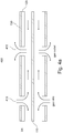
- FIG. 4B shows two reactor modules coupled by a coaxial cable 420.
- Both reactor modules are arranged substantially parallel in this figure, which should only serve as an exemplary arrangement.
- Each module has its own reaction length, but as the arrangement is kind of a "folded" arrangement, the total geometrical length of the reactor may be smaller than an unfolded length. In other words, this arrangement may allow for a compact direct barrier discharge reactor size, with no or few compromises in the reaction length.
- FIG. 4B may additionally disclose a concentric electrode arrangement, wherein 110 may be an inner or first electrode of the DBD reactor and 130 may be a second or outer electrode.
- Other variants may be possible, e.g. flat electrodes.
- multiple smaller reactors with axial flow of the feed gas, arranged in parallel, connected electrically in series with coaxial cables 210 are possible.
- Plasma reactor modules may also be arranged in an electrically parallel manner. This may change an input impedance accordingly. From an electrical point of view, the input impedances of two or more reactor modules or reactor elements may thereby form a parallel circuit. This can be important to match to the output impedance of connecting cable.
- Another embodiment of the present application may disclose a plasma reactor, wherein a physical (geometrical) length of the plasma reactor is shorter than the sum of a length of all plasma reactor modules in series connection.
- a plasma reactor length may be a physical length of the reactor which can be shorter than the total length, if multiple plasma reactor elements or modules are stacked or folded. This may enable, that a normally very long reactor of a known type, can be built geometrically much shorter thereby having substantially the same or very similar gas transition or reactor length. In this way, a geometrically short plasma reactor for a DBD system may have similar characteristics for producing active species than a normal long build reactor.
- a plasma reactor according to one or more aspects of the present application discloses that at least one of the one or more plasma reactor modules may preferably have the same characteristic impedance as the pulse generator 240. This may enable, that energy from the pulse generator 240 is not reflected back from the plasma reactor or from the plasma reactor modules but is completely fed into the plasma reactor.
- the pulse generator 240 may not necessarily be matched to the cable/reactor impedance.
- a further embodiment discloses a plasma reactor according to one or more aspects of the present application, wherein an electrical connection between the plasma reactor modules to provide a series connection is made with cables 210 (lines), the cables 210 having substantially a same or very similar characteristic impedance as the plasma reactor modules.
- the cables 210 may also be used to connect one side of the DBD reactor to the voltage pulse source.
- Z cable is a wave impedance of the cable.
- An output impedance of the pulse generator 240 which is two times the line (cable) impedance may also be possible as well as 0 ohm impedance or near 0 ohm impedance at the output of the pulse generator 240.
- a plasma reactor according to one or more aspects of the application may be disclosed, wherein an electrical structure of the plasma reactor modules 100 and the electric cables 210, 420 correspond to a wave guide.
- values of geometric dimensions of the one or more plasma reactor modules are configured such, that a predetermined characteristic impedance for each of the reactor modules or elements is obtained.
- FIG. 1 shows a coaxial structure of a plasma rector module according to the present application.
- a cylinder concentric arrangement like coaxial arrangement, also elongated rectangular beams or other arrangements (e.g. plate-knife) of the electrodes are possible - they are typically extrusions of a 2d shape into the propagation direction.
- elongated rectangular beams or other arrangements e.g. plate-knife
- a plasma reactor according to one or more aspects of the previous application is disclosed, wherein the characteristic impedance of a plasma reactor module 100 or the plasma reactor may be dependent on values of one or more from the group: radial dimension, dielectric, gap size.
- the radial dimension, dielectric thickness, gap size are chosen such that a resulting characteristic impedance may match the characteristic impedance of cables, connecting the plasma reactor modules.
- the plasma reactor may have a gas transition length.
- the gas transition length is a length between an inflow or inlet 410 of a fluid, arranged at a first side of the plasma reactor module, and an outflow or outlet for the fluid, arranged at a second side of the plasma reactor.
- a gas transition length is the length that a volume element of a fluid, which is fed in the DBD reactor, travels through the gap of the DBD reactor, during which it is enriched with active species.
- This gas transition length may be equal to a total length of a reactor or a reactor module/element or a fraction of it. It is important to note - as seen in the depicted embodiments - that even though the electrical connection of the reactors is typically serial, the gas flow pattern can be completely different.
- Fluids can preferably be specific gases like oxygen (O2), nitrogen, (N2) or normal air.
- Normal air e.g. may consist of about 21% oxygen and 78% nitrogen.
- Adapting operation parameters of the plasma reactor of the present application may enable that different active species like ozone (O3) or nitrogen oxide (NOx) can be generated from normal air. This may save costs arising from usage of pure gases like oxygen or nitrogen have to be supplied by specific additional pressure gas containments. Pure gases from extra containments may be used as well.
- O3 ozone
- NOx nitrogen oxide
- a fluid preferably a gas like oxygen, environmental air or nitrogen, is fed into a discharge volume (gap between electrodes and dielectric) in the plasma reactor.
- the discharge volume is preferably arranged in an area between an electrode and a dielectric (gap).
- the pulse duration is chosen according to the length of the reactor, so that l ⁇ v pulse t pulse ⁇ 10 l .
- the maximum current that should be supplied by the voltage source may be dependent on the voltage and the wave impedance of the cable. It does not depend on the length (size) of the reactor.
- DBD reactors of different lengths can be operated with the same current, and only the pulse duration has to be adjusted according to the reactor length.
- Another advantage of this solution is that no matching circuit/element is needed to match the power source to the reactor.
- a total amount of generated active species is adjusted by the reactor length.
- the reactor does not necessarily have to be along a straight line, it is only important to keep the wave impedance constant.
- the necessary reactor length can exceed 100 m.
- a plasma reactor according to one or more aspects of the application is disclosed, wherein a total gas transition length of the plasma reactor is equal to the total length of the plasma reactor or a fraction of the total length of the plasma reactor.
- the one or more plasma reactor modules may have more than one inflows 410 and more than one outflows 410 (see FIG. 4c ) for a fluid between the first side and the second side.
- FIG. 4 a to 4c shows some variants.
- FIGs. 4a and 4c show examples of variants for the gas flow inside the reactor according to embodiments of the application; here shown for a concentric electrode. Different alternatives may be possible.
- the gas flow in Fig. 4a is an essentially axial gas flow; the gas flow in Fig. 4c is an essentially radial gas flow. Whether the gas flow can be considered as radial or axial depends on the dimensions. (e.g. relation of distance between in-/outflows of gas/species, diameter/radius of the reactor).
- More gas in-/outflows may enable a better reaction quality in the generation of active species. More outflows may be advantageous, e.g. if the outflow is mixed with another fluid and a good mixing quality is intended. More outflows may decontaminate a greater amount of water in the same time. Pulse characteristics have to be adapted on this.
- a folded reactor may act as a centralized source of active species e.g. ozone
- the modular approach also allows to have spatially separate (possibly many meters apart) sources connected only by a coaxial cable. This may be used in applications, where the output is needed at different locations and can then be provided in-situ without need for a long gas tube connections between the locations (possibly example is plasma surface treatment of polymers).
- a plasma reactor according to one or more aspects of the present application is disclosed, wherein the one or more plasma reactor modules may have an individual geometry and wherein the plasma reactor modules may have a same impedance.
- one or more plasma reactor modules or elements in a plasma reactor may be sized differently, e.g. to geometrically fit them into a specific housing.
- the plasma reactor may further comprise a network interface for connecting controlling elements of the plasma reactor to a data network.
- the controlling elements of the plasma reactor may be operatively connected to the network interface for at least one of carrying out a command received from the data network and sending device status information to the data network.
- a plasma reactor with a DBD system for example arranged in a ship for disinfecting ballast water, may be externally controlled from an outside control institution. According to specific needs, it can be necessary, to adapt the kind and the amount of generated species from an outside accordingly.
- a plasma reactor according to one or more aspects may be disclosed, wherein the network interface is configured to transceive digital signal/data between the controlling elements of the plasma reactor and the data network, wherein the digital signal/data may include operational command and/or information about the controlling elements of the plasma reactor or a status of the reactor or the network and further comprises a processing unit for converting the signal into a digital signal or processing the signal.
- the reactor as presented in the current application is built preferably as an elongated device (elongated electrodes) in a preferably coaxial arrangement, having substantially the same or very similar impedance as the cable that is connecting to the high voltage power supply (pulse voltage source).
- the presented plasma reactor comprises single plasma reactor modules or plasma reactor elements.
- the elements/modules of the plasma reactor may be shaped differently (e.g. different length or different diameter each) but the plasma reactor modules/elements may have substantially the same characteristic impedance.
- the presented layout of the reactor geometry can be scaled to different sizes to generate a proper amount of active species.
- the required amount of active species depends on a respective application.
- the reactor modules or elements can be switched in series via matched connection cables, preferably transmission lines. Special variants use internal reflection at the end of the reactor to double the voltage. This enables to use a pulse generator 240 with a lower maximum voltage since a reflected wave superimposes with the wave coming from generator 240.
- the series connection of the plasma reactor modules 100, 220 may be terminated in a way, that a reflection factor of "+1" or "-1" occurs.
Landscapes
- Physics & Mathematics (AREA)
- Engineering & Computer Science (AREA)
- Plasma & Fusion (AREA)
- Spectroscopy & Molecular Physics (AREA)
- Optics & Photonics (AREA)
- Electromagnetism (AREA)
- Plasma Technology (AREA)
- Physical Or Chemical Processes And Apparatus (AREA)
Priority Applications (6)
| Application Number | Priority Date | Filing Date | Title |
|---|---|---|---|
| EP18212650.8A EP3668280A1 (fr) | 2018-12-14 | 2018-12-14 | Réacteur à plasma non thermique allongé pour un couplage optimal à une alimentation pulsée |
| US17/311,533 US20220022308A1 (en) | 2018-12-14 | 2019-12-13 | Elongated Non-Thermal Plasma Reactor For Optimal Coupling To Pulsed Power Supply |
| FIEP19816797.5T FI3895506T3 (fi) | 2018-12-14 | 2019-12-13 | Pitkänomainen ei-terminen plasmareaktori optimaalista pulssivirtalähteeseen kytkemistä varten |
| PCT/EP2019/085082 WO2020120740A1 (fr) | 2018-12-14 | 2019-12-13 | Réacteur à plasma non thermique allongé pour couplage optimal à une alimentation électrique pulsée |
| EP19816797.5A EP3895506B1 (fr) | 2018-12-14 | 2019-12-13 | Réacteur à plasma non thermique allongé pour un couplage optimal à une alimentation pulsée |
| CN201980081867.5A CN113196887B (zh) | 2018-12-14 | 2019-12-13 | 用于优化的到脉冲电源的耦合的细长非热等离子体反应器 |
Applications Claiming Priority (1)
| Application Number | Priority Date | Filing Date | Title |
|---|---|---|---|
| EP18212650.8A EP3668280A1 (fr) | 2018-12-14 | 2018-12-14 | Réacteur à plasma non thermique allongé pour un couplage optimal à une alimentation pulsée |
Publications (1)
| Publication Number | Publication Date |
|---|---|
| EP3668280A1 true EP3668280A1 (fr) | 2020-06-17 |
Family
ID=64665658
Family Applications (2)
| Application Number | Title | Priority Date | Filing Date |
|---|---|---|---|
| EP18212650.8A Withdrawn EP3668280A1 (fr) | 2018-12-14 | 2018-12-14 | Réacteur à plasma non thermique allongé pour un couplage optimal à une alimentation pulsée |
| EP19816797.5A Active EP3895506B1 (fr) | 2018-12-14 | 2019-12-13 | Réacteur à plasma non thermique allongé pour un couplage optimal à une alimentation pulsée |
Family Applications After (1)
| Application Number | Title | Priority Date | Filing Date |
|---|---|---|---|
| EP19816797.5A Active EP3895506B1 (fr) | 2018-12-14 | 2019-12-13 | Réacteur à plasma non thermique allongé pour un couplage optimal à une alimentation pulsée |
Country Status (5)
| Country | Link |
|---|---|
| US (1) | US20220022308A1 (fr) |
| EP (2) | EP3668280A1 (fr) |
| CN (1) | CN113196887B (fr) |
| FI (1) | FI3895506T3 (fr) |
| WO (1) | WO2020120740A1 (fr) |
Families Citing this family (1)
| Publication number | Priority date | Publication date | Assignee | Title |
|---|---|---|---|---|
| US20240066161A1 (en) * | 2021-08-09 | 2024-02-29 | TellaPure, LLC | Methods and apparatus for generating atmospheric pressure, low temperature plasma |
Citations (2)
| Publication number | Priority date | Publication date | Assignee | Title |
|---|---|---|---|---|
| US20060244386A1 (en) * | 2005-05-02 | 2006-11-02 | Hooke William M | Pulsed dielectric barrier discharge |
| WO2012170534A1 (fr) * | 2011-06-07 | 2012-12-13 | International Technology Center | Décharge de barrière diélectrique auto-accordée |
Family Cites Families (17)
| Publication number | Priority date | Publication date | Assignee | Title |
|---|---|---|---|---|
| JPS5944797A (ja) * | 1982-09-07 | 1984-03-13 | 増田 閃一 | 物体の静電的処理装置 |
| JP2001514444A (ja) * | 1997-08-26 | 2001-09-11 | アプライド マテリアルズ インコーポレイテッド | プラズマ処理チャンバへ安定した電力を送ることができる装置及び方法 |
| US6190507B1 (en) * | 1998-07-24 | 2001-02-20 | The United States Of America As Represented By The Department Of Energy | Method for generating a highly reactive plasma for exhaust gas aftertreatment and enhanced catalyst reactivity |
| US6685803B2 (en) * | 2001-06-22 | 2004-02-03 | Applied Materials, Inc. | Plasma treatment of processing gases |
| AUPS220302A0 (en) * | 2002-05-08 | 2002-06-06 | Chang, Chak Man Thomas | A plasma formed within bubbles in an aqueous medium and uses therefore |
| US7063819B2 (en) * | 2003-03-21 | 2006-06-20 | The Regents Of The University Of California | Nonthermal plasma processor utilizing additive-gas injection and/or gas extraction |
| US7521026B2 (en) * | 2003-03-21 | 2009-04-21 | Los Alamos National Security, Llc | Field-enhanced electrodes for additive-injection non-thermal plasma (NTP) processor |
| US6906280B2 (en) * | 2003-03-21 | 2005-06-14 | The Regents Of The University Of California | Fast pulse nonthermal plasma reactor |
| JP5256415B2 (ja) * | 2008-03-14 | 2013-08-07 | イマジニアリング株式会社 | 燃焼室の排気ガス後処理装置 |
| WO2009146432A1 (fr) * | 2008-05-30 | 2009-12-03 | Colorado State University Research Foundation | Dispositif de source chimique à base de plasma et procédé d'utilisation de celle-ci |
| JP5745858B2 (ja) * | 2008-12-27 | 2015-07-08 | 隆男 浪平 | パルス放電発生方法 |
| US9932252B2 (en) * | 2013-05-01 | 2018-04-03 | Nch Corporation | System and method for treating water systems with high voltage discharge and ozone |
| US10283327B2 (en) * | 2013-12-19 | 2019-05-07 | The Board Of Trustees Of The Leland Stanford Junior University | Apparatus and methods for generating reactive gas with glow discharges |
| CN106232528B (zh) * | 2014-04-24 | 2019-10-22 | Nch公司 | 利用高压放电和臭氧来处理水系统中的水的系统和方法 |
| CN105080302A (zh) * | 2015-08-17 | 2015-11-25 | 杭州科瑞特环境技术有限公司 | 一种紫外光-等离子体协同降解有机废气装置及其方法 |
| DE102016204252A1 (de) * | 2016-03-15 | 2017-09-21 | Siemens Aktiengesellschaft | Vorrichtung und Verfahren zur Erzeugung eines nicht-thermischen Plasmas zur Massevergasung mittels eines Pulsgenerators |
| CN108173534A (zh) * | 2018-02-09 | 2018-06-15 | 中国科学院电工研究所 | 一种双极性传输线型纳秒脉冲发生器 |
-
2018
- 2018-12-14 EP EP18212650.8A patent/EP3668280A1/fr not_active Withdrawn
-
2019
- 2019-12-13 EP EP19816797.5A patent/EP3895506B1/fr active Active
- 2019-12-13 FI FIEP19816797.5T patent/FI3895506T3/fi active
- 2019-12-13 CN CN201980081867.5A patent/CN113196887B/zh active Active
- 2019-12-13 WO PCT/EP2019/085082 patent/WO2020120740A1/fr not_active Ceased
- 2019-12-13 US US17/311,533 patent/US20220022308A1/en not_active Abandoned
Patent Citations (2)
| Publication number | Priority date | Publication date | Assignee | Title |
|---|---|---|---|---|
| US20060244386A1 (en) * | 2005-05-02 | 2006-11-02 | Hooke William M | Pulsed dielectric barrier discharge |
| WO2012170534A1 (fr) * | 2011-06-07 | 2012-12-13 | International Technology Center | Décharge de barrière diélectrique auto-accordée |
Non-Patent Citations (1)
| Title |
|---|
| JUNFENG RAO ET AL: "A Novel All Solid-State Sub-Microsecond Pulse Generator for Dielectric Barrier Discharges", IEEE TRANSACTIONS ON PLASMA SCIENCE, IEEE SERVICE CENTER, PISCATAWAY, NJ, US, vol. 41, no. 3, 7 March 2013 (2013-03-07), pages 564 - 569, XP011495310, ISSN: 0093-3813, DOI: 10.1109/TPS.2012.2228885 * |
Also Published As
| Publication number | Publication date |
|---|---|
| CN113196887B (zh) | 2024-05-24 |
| US20220022308A1 (en) | 2022-01-20 |
| EP3895506B1 (fr) | 2023-11-01 |
| EP3895506A1 (fr) | 2021-10-20 |
| WO2020120740A1 (fr) | 2020-06-18 |
| CN113196887A (zh) | 2021-07-30 |
| FI3895506T3 (fi) | 2024-01-30 |
Similar Documents
| Publication | Publication Date | Title |
|---|---|---|
| KR100230169B1 (ko) | 배기가스 처리장치 및 방법과 이들에 사용되는 펄스발생장치 | |
| US5603893A (en) | Pollution treatment cells energized by short pulses | |
| JP7821200B2 (ja) | マイクロ波を用いたプラズマ発生のシステム及び方法 | |
| JP4658506B2 (ja) | パルスアークプラズマ生成用電源回路及びパルスアークプラズマ処理装置 | |
| EP3894359B1 (fr) | Décharge à barrière diélectrique pour traitement d'eau de ballast utilisant une commande de forme de tension optimisée | |
| WO2008011817A1 (fr) | Appareil et système de déshydratation de pétrole brut | |
| EP3895506B1 (fr) | Réacteur à plasma non thermique allongé pour un couplage optimal à une alimentation pulsée | |
| CN101909661A (zh) | 饮料杀菌设备 | |
| CN103596717B (zh) | 高频电源装置 | |
| US10125032B2 (en) | Device for the photochemical treatment or cleaning of a liquid medium | |
| JP6423887B2 (ja) | オゾン発生器 | |
| CN106788343A (zh) | 一种基于高储能密度液体介质的卷绕型带状脉冲形成线 | |
| Jang et al. | Pulsed-power system for leachate treatment applications | |
| Fukawa et al. | Consideration of reactor configuration of high yield ozonizer by nanosecond pulsed power discharge | |
| WO2012120928A1 (fr) | Structure de réacteur et dispositif de traitement par plasma | |
| CN110392478B (zh) | 一种反相双高压三环结构安全射流装置 | |
| JP2018038961A (ja) | 流体浄化装置および流体浄化方法 | |
| Matsumoto et al. | Development of low impedance nanosecond pulse generator and construction measurement environment | |
| CN106788342A (zh) | 电参数在线可调高功率脉冲形成线及电参数调节方法 | |
| HK40100629A (zh) | 用於基於等离子体的治理的系统和方法 | |
| AU744677B2 (en) | Pulse generator | |
| CN120172492A (zh) | 一种等离子体污水处理装置 | |
| HK40065510B (zh) | 用於基於等离子体的治理的系统和方法 | |
| Georgescu | Methods to minimize the global energy cost in experiments with pulsed corona plasmas for pollution control | |
| JPS60127206A (ja) | オゾン発生装置 |
Legal Events
| Date | Code | Title | Description |
|---|---|---|---|
| PUAI | Public reference made under article 153(3) epc to a published international application that has entered the european phase |
Free format text: ORIGINAL CODE: 0009012 |
|
| STAA | Information on the status of an ep patent application or granted ep patent |
Free format text: STATUS: THE APPLICATION HAS BEEN PUBLISHED |
|
| AK | Designated contracting states |
Kind code of ref document: A1 Designated state(s): AL AT BE BG CH CY CZ DE DK EE ES FI FR GB GR HR HU IE IS IT LI LT LU LV MC MK MT NL NO PL PT RO RS SE SI SK SM TR |
|
| AX | Request for extension of the european patent |
Extension state: BA ME |
|
| STAA | Information on the status of an ep patent application or granted ep patent |
Free format text: STATUS: THE APPLICATION IS DEEMED TO BE WITHDRAWN |
|
| 18D | Application deemed to be withdrawn |
Effective date: 20201218 |