EP3668285B1 - System zum lösbaren verbinden eines ersten vorrichtungsgehäuses mit einem zweiten vorrichtungsgehäuse und verbindungsanordnung - Google Patents
System zum lösbaren verbinden eines ersten vorrichtungsgehäuses mit einem zweiten vorrichtungsgehäuse und verbindungsanordnung Download PDFInfo
- Publication number
- EP3668285B1 EP3668285B1 EP18212600.3A EP18212600A EP3668285B1 EP 3668285 B1 EP3668285 B1 EP 3668285B1 EP 18212600 A EP18212600 A EP 18212600A EP 3668285 B1 EP3668285 B1 EP 3668285B1
- Authority
- EP
- European Patent Office
- Prior art keywords
- locking
- section
- headed bolt
- recess
- bolt
- Prior art date
- Legal status (The legal status is an assumption and is not a legal conclusion. Google has not performed a legal analysis and makes no representation as to the accuracy of the status listed.)
- Active
Links
Images



Classifications
-
- H—ELECTRICITY
- H05—ELECTRIC TECHNIQUES NOT OTHERWISE PROVIDED FOR
- H05K—PRINTED CIRCUITS; CASINGS OR CONSTRUCTIONAL DETAILS OF ELECTRIC APPARATUS; MANUFACTURE OF ASSEMBLAGES OF ELECTRICAL COMPONENTS
- H05K5/00—Casings, cabinets or drawers for electric apparatus
- H05K5/30—Side-by-side or stacked arrangements
-
- F—MECHANICAL ENGINEERING; LIGHTING; HEATING; WEAPONS; BLASTING
- F16—ENGINEERING ELEMENTS AND UNITS; GENERAL MEASURES FOR PRODUCING AND MAINTAINING EFFECTIVE FUNCTIONING OF MACHINES OR INSTALLATIONS; THERMAL INSULATION IN GENERAL
- F16B—DEVICES FOR FASTENING OR SECURING CONSTRUCTIONAL ELEMENTS OR MACHINE PARTS TOGETHER, e.g. NAILS, BOLTS, CIRCLIPS, CLAMPS, CLIPS OR WEDGES; JOINTS OR JOINTING
- F16B21/00—Means for preventing relative axial movement of a pin, spigot, shaft or the like and a member surrounding it; Stud-and-socket releasable fastenings
- F16B21/09—Releasable fastening devices with a stud engaging a keyhole slot
-
- H—ELECTRICITY
- H05—ELECTRIC TECHNIQUES NOT OTHERWISE PROVIDED FOR
- H05K—PRINTED CIRCUITS; CASINGS OR CONSTRUCTIONAL DETAILS OF ELECTRIC APPARATUS; MANUFACTURE OF ASSEMBLAGES OF ELECTRICAL COMPONENTS
- H05K5/00—Casings, cabinets or drawers for electric apparatus
- H05K5/02—Details
- H05K5/0217—Mechanical details of casings
- H05K5/0221—Locks; Latches
-
- F—MECHANICAL ENGINEERING; LIGHTING; HEATING; WEAPONS; BLASTING
- F16—ENGINEERING ELEMENTS AND UNITS; GENERAL MEASURES FOR PRODUCING AND MAINTAINING EFFECTIVE FUNCTIONING OF MACHINES OR INSTALLATIONS; THERMAL INSULATION IN GENERAL
- F16B—DEVICES FOR FASTENING OR SECURING CONSTRUCTIONAL ELEMENTS OR MACHINE PARTS TOGETHER, e.g. NAILS, BOLTS, CIRCLIPS, CLAMPS, CLIPS OR WEDGES; JOINTS OR JOINTING
- F16B2200/00—Constructional details of connections not covered for in other groups of this subclass
- F16B2200/20—Connections with hook-like parts gripping behind a blind side of an element to be connected
Definitions
- the present invention relates to a system for releaseably connecting a first device housing with a second device housing.
- the present invention also relates to a connection arrangement that includes such a system.
- housings of multiple devices In device systems, and especially in electronic device systems such as e. g. measurement or communication device systems, housings of multiple devices often have to be connected to each other. Usually, such housings are stacked and the housings of the devices are therefore screwed or bolted together. Often, additional attachment parts such as mounting or fixing brackets are used to connect the housings and to achieve a certain mechanical stability of the stack.
- DE 102 28 755 A1 describes a housing for fixing to a wall, said housing comprising a plate-shaped housing element having a slot-shaped recess into which a carrier body fixed to a wall and projecting from the surface of said wall can be introduced, in an introduction region in an assembly position of the housing.
- Said carrier body can take on a fixing position by moving the housing into a suspension region.
- the housing element is arranged on the carrier body, an end piece of the carrier body supporting said housing element in a hook-like manner.
- At least one elastic means is arranged in the recess, said elastic means being elastically deflected when the carrier body is inserted and snapping back in the fixing position.
- the problem to be solved by the present invention is to provide a new and improved system for releaseably connecting a first device housing with a second device housing, and a connection arrangement that includes such a system.
- the present invention provides a system for releaseably connecting a first device housing with a second device housing comprising the features of claim 1.
- the invention provides a system which allows a connection of device housings which is mechanically stable and easy to assemble and disassemble.
- no tools and no additional attachment parts, such as mounting or fixing brackets, are necessary for assembly and disassembly. Instead, the movable locking element is just moved into an unlocking position to disassemble the housings. In this way, the connection of the housings can be easily disconnected without application of high forces.
- Each connection unit of the system comprises two parts, one comprising the headed bolt and one comprising the keyhole-shaped recess, which can be connected in a form fitting manner.
- a high strength connection can be provided without necessity for a permanent connection.
- a plurality of two, three, four or more device housings may be connected, in particular stacked.
- the system is configured to connect device housings of similar stand space or footprint, especially similar device housings. In this way, flexibility of use, transportation and even mobile use of corresponding devices housed in the device housings is simplified.
- the movable locking element can be configured movable in various ways.
- the movable locking element can be configured movable by hand or by a moving mechanism.
- the movable locking element may be configured magnetically movable, movable by an actuator, or the like.
- the system may comprise any number of connection units equal to or higher than three connection units. In this way, the system provides for a statically determinate connection of the device housings. Accordingly, a strong connection is provided, in particular without considerable play or backlash.
- the locking mechanism comprises a handle for moving the locking element from the locking position into an unlocking position.
- the system allows tool free manipulation of the locking mechanism, in particular for disassembly.
- the locking element is preloaded by a spring element such that the locking element is resiliently held in the locking position.
- the locking element can be provided with an automatic locking function.
- the locking element may be configured self-locking, in particular as a snap-in locking element.
- the locking mechanism comprises a locking catch.
- a locking catch may be configured for example to catch the headed bolt in a certain position.
- the locking catch may be configured to catch the device housing or a latch in a certain position of the locking element. Accordingly, either the headed bolt or the locking element can be automatically locked in a predetermined position.
- the locking catch is configured to catch the headed bolt in the second section of the recess. Therefore, the locking catch is arranged such that the headed bolt is locked automatically by the locking element when inserted into the keyhole-shaped recess and moved from the first section to the second section.
- the locking catch is configured to catch or hold the locking element in the locking position. Therefore, the locking catch is in particular arranged such that the locking element is locked automatically when it is moved from an unlocked position to the locking position. For example, the locking catch in the locking position of the locking element catches a predetermined part of the device housing or a latch attached thereto.
- the locking catch is formed as a ramp or nose with a rising side and an edge.
- the rising side cooperates either with the headed bolt or the housing while the locking element is moved, preferably such that the locking element is loaded.
- the locking catch snaps over such that the locking element is automatically locked in the locking position and/or the headed bolt is automatically locked in the second section of the keyhole shaped recess.
- the locking catch can be released e. g. by moving it manually back over the edge.
- the locking catch is attached to or integrally formed with the locking element. In this way, the locking catch can be released by manually moving the locking element back into the unlocked position.
- the locking element is configured as a slider transversely movable with respect to the bolt axis.
- the slider is movable only in one translational axis. In this way, the locking element is realized with a very flat design.
- the slider comprises a stop configured to stop the locking element in the locking position. Furthermore, the slider may comprise another stop configured to stop the locking element in the unlocking position. In this way, the locking element has predefined locking and unlocking positions.
- the first section of the keyhole-shaped recess is wider than the second section and wider than a biggest protruding cross sectional part of the headed bolt, especially the head thereof.
- the headed bolt can be easily inserted into the keyhole-shaped recess in the first section and locked in the second section.
- the second section of the keyhole-shaped recess is smaller than the biggest protruding cross sectional part of the headed bolt.
- This biggest protruding cross sectional part is in particular formed as the head of the headed bolt.
- the second section is however big enough to receive a smaller cross-sectional part of the bolt, in particular a smaller or regular bolt diameter. In this way, the bolt can be easily held in the second section.
- the headed bolt is configured as mushroom headed bolt.
- the mushroom head design on one hand provides for the desired form lock.
- the mushroom head design prevents a tendency to stick in the recess, even if the bolt is positioned tilted with respect to the keyhole-shaped recess.
- the present invention provides a connection arrangement comprising a first device housing and a second device housing coupled to the first device housing with a releasable connecting system.
- the connecting system comprises at least three connection units, wherein each of the connection units comprises a headed bolt and a corresponding keyhole-shaped recess.
- the keyhole-shaped recess is configured for receiving the headed bolt in such a manner that the headed bolt can be inserted into the recess in a first section and held in the recess in a second section.
- At least one of the connection units comprises a locking mechanism configured for locking the bolt in the second section of the recess.
- the locking mechanism comprises a movable locking element which is movable with respect to the headed bolt and configured to hold the headed bolt in the second section of the recess in a locking position.
- the invention is configured to allow a connection of the device housings which is mechanically stable and easy to assemble and disassemble.
- no tools and no additional attachment parts such as mounting or fixing brackets are necessary for assembly and disassembly of the arrangement.
- the arrangement may also comprise a plurality of more than two device housings, for example three, four or more device housings connected, in particular stacked, by a similar system.
- each device housing may be equipped with the headed bolts on one side and keyhole-shaped recesses on another side, in particular an opposite side.
- the device housings have similar stand spaces or footprints.
- the device housings may be configured as similar housings.
- the device housings may be configured for example as housings for electronic measurement or communication or energy supply device systems.
- such device systems may comprise MIMO (Multiple Input Multiple Output) devices, battery pack devices, or the like.
- system of the connection arrangement may comprise the features according to any of the embodiments of a system as described above.
- the bolt is fixed to the first device housing.
- the bolt comprises an outer thread and the first device housing comprises a threaded hole into which the bolt may be screwed.
- the bolts can therefore be removed from the first device housing, for example if a device is to be used standalone.
- the bolt may be permanently fixed to the housing, for example welded to the housing.
- the keyhole-shaped recess is formed in the second housing.
- the recess may be formed as a recess of the housing directly in the housing material. In this way, the connection system provides for a very flat integrated design.
- the present invention provides a system for releaseably connecting a first device housing with a second device housing.
- the system comprises at least three connection units, wherein each of the connection units comprises a headed bolt and a corresponding keyhole-shaped recess.
- the keyhole-shaped recess is configured for receiving the headed bolt in such a manner that the headed bolt can be inserted into the recess in a first section and held in the recess in a second section.
- At least one of the connection units comprises a locking mechanism configured for locking the bolt in the second section of the recess.
- the locking mechanism comprises a flexible buffer element arranged in the second section of the keyhole-shaped recess.
- the buffer element is configured to load the headed bolt with a frictional force to hold the headed bolt in the second section of the recess in a locking position.
- the invention is configured to allow a connection of the device housings which is easy to assemble and disassemble.
- no tools and no additional attachment parts such as mounting or fixing brackets are necessary for assembly and disassembly.
- the bolt can be loaded with a frictional force by inserting it into the recess in the first section and pushing it into the second section in which the bolt is then held by the frictional force applied by the buffer element.
- the buffer element may be configured to allow unlocking of the headed bolt by overcoming the frictional force manually, for example by manually pushing the bolt back from the second section into the first section of the recess.
- the buffer element can be configured more flexible than the keyhole-shaped recess.
- the buffer element may be formed of a material different from the material in which the recess is formed.
- the buffer element may comprise a flexible polymer, such as an elastomer or thermoplastic elastomer.
- the buffer element may comprise a spring or spring plate configured to apply a frictional force.
- the present invention provides a connection arrangement comprising a first device housing and a second device housing coupled to the first device housing with a releasable connecting system.
- the connecting system is configured according to the invention.
- the invention is configured to provide a connection of the device housings which is easy to assemble and disassemble.
- no tools and no additional attachment parts such as mounting or fixing brackets are necessary for assembly and disassembly.
- the bolt can be loaded with a frictional force by inserting it into the recess in the first section and pushing it into the second section in which the bolt is then held by the frictional force applied by the buffer element.
- the arrangement may comprise a plurality of more than two device housings, for example three, four or more device housings connected by a similar system, in particular stacked.
- the device housings have similar stand spaces or footprints.
- the device housings are configured as similar housings.
- system of the connection arrangement may comprise the features according to any of the embodiments of a system as described above.
- connection arrangement may comprise the features according to any of the embodiments of an arrangement as described above.
- a system 1 for releasably connecting a first device housing 2 and a second device housing 3 is illustrated.
- the system 1 comprises for example only a number of four connection units 4. In other embodiments, only three or more than four connection units may be provided. However, the system comprises at least 3 connection units.
- connection units comprises a headed bolt 5. Furthermore, each of the connection units 4 comprises a keyhole-shaped recess 6 corresponding to the headed bolt 5.
- the bolts 5 according to Fig. 1 are configured as mushroom headed bolts and mounted on an upper side of the device housings 2, 3 and the keyhole-shaped recesses 6 are formed on the bottom side of the device housings 2, 3.
- the bolts 5 and recesses 6 are possible in further embodiments as long as they are situated at corresponding interfaces of the device housings 2, 3.
- Fig. 2 is a detailed bottom view of the second device housing 3 of Fig. 1 .
- the keyhole-shaped recess 6 is configured for receiving the headed bolt 5.
- the keyhole-shaped recess 6 therefore comprises a first section 7, in which the headed bolt 5 can be inserted into the recess 6.
- the recess 6 comprises a second section 8 configured to hold the headed bolt in the recess 6.
- the second section 8 is configured to positively engage the headed bolt.
- the first section 7 of the keyhole-shaped recess 6 is formed wider than the second section 8 and wider than a biggest protruding cross sectional part of the headed bolt 5, formed in particular by the head. Accordingly, the headed bolt 5 can be inserted into the first section 7 of the keyhole-shaped recess 6. Furthermore, the second section 8 of the keyhole-shaped recess 6 is smaller than the head of the headed bolt 5 but big enough to receive a smaller cross-sectional part of the bolt with a smaller bolt diameter such that the bolt can be locked in the second section.
- the bolts 5 may be inserted into the recesses 6 by putting a bottom side of the second device housing 3 onto an upper side of the first device housing 2.
- the second housing 3 is positioned in such a way that the first sections 7 of the recesses are aligned with the headed bolts 5, as illustrated by the dashed lines in Fig. 1 .
- the second housing 3 may then be lowered relative to the first housing 2 as illustrated by the arrow A.
- the second device housing 3 can be translated in the longitudinal direction as illustrated by the arrow B, parallel to a central axis of the keyhole-shaped recesses 6.
- the headed bolts 5 are moved within the recesses 6 from the first sections 7 to the second sections 8 whereby the heads of the headed bolts 5 engage with the material, in particular the housing material, in which the recesses 6 are formed.
- connection units 6 comprises a locking mechanism 9 configured for locking the respective headed bolt 5 in the respective second section 8 of the recess 6.
- a connection arrangement 20 can be formed of the first and the second device housings 2, 3 and the connecting system 1.
- Fig. 3 is a perspective view of a connection arrangement 20.
- the locking mechanism 9 comprises a movable locking element 10 which is movable with respect to the headed bolt 5 and configured to hold the headed bolt 5 in the second section 8 of the recess 6 in a locking position.
- Fig. 4A is a detailed view of the locking element 10 in a locking position.
- the movable locking element 10 can be manually moved from the locking position into an unlocking position.
- the headed bolt 5 can be moved back from the second section 8 to the first section 7 of the recess 6 in order to remove it from the recess 6. Therefore, the second device housing 3 can be translated as illustrated by arrow C in Fig. 3 in order to move the headed bolts 5 of all four connection units 4 back into the first sections 7 of the keyhole-shaped recesses 6. The second housing 3 may then be lifted up from the first housing 2, as illustrated by arrow D, to remove the bolts 5 from the recesses 6 and separate the housings 2, 3.
- any other plurality of three, four or more device housings may be connected.
- Fig. 5A is a schematic longitudinal sectional view of a locking mechanism 9 according to an an example not in accordance with the claimed invention
- the locking mechanism 9 with the movable locking element 10 is arranged in a connection unit 4.
- the keyhole-shaped recess 6 of the connection unit 4 is formed in the bottom wall 13 of the second device housing 3 and the headed bolt 5 of the connection unit 4 is fixed to an upper wall 12 of the first device housing 2.
- the bolt 5 comprises an outer thread and the first device housing comprises a threaded hole into which the bolt is screwed.
- the locking element is connected with a spring element 11, for example a preloaded spring plate, such that the locking element 10 is resiliently held in the locking position.
- the locking element 10 of the locking mechanism 9 comprises a locking catch 14, formed as an edge of a recess of the locking element 10.
- the catch 14 is configured to catch the headed bolt 5, in particular a head 19 of the headed bolt 5, in the second section 8 of the recess 6 when it is inserted into the second section. This means, the headed bolt 5 is locked automatically by the locking element 10 when the head 19 is inserted into the keyhole-shaped recess 6 and moved from the first section 7 to the second section 8.
- Fig. 5B is a schematic lateral sectional view of the locking mechanism 9 according to Fig. 5A in the locking position.
- the locking element 10 extends through an opening 17 of the second housing 3 and comprises a handle 16 for manual manipulation.
- the spring element 11 On an opposite side of the locking element 10, the spring element 11 is attached to the bottom wall 13 of the second housing 3 with a fastening element 15. In the shown locking position, the spring element 11 pushes the locking element 10 downwards such that the catch 14 locks the headed bolt 5 in the second section 8 of the recess 6.
- Fig. 5C is a schematic lateral sectional view of the locking mechanism according to Fig. 5A in an unlocking position.
- the locking element 10 In order to reach the unlocking position, the locking element 10 is pushed upwards at the handle 16 such that it is resiliently tilted against the spring force of the spring element 11. In this way, the locking element 10 is lifted in such a way that the locking catch 14 and the head 19 of the headed bolt 5 disengage. Accordingly, the headed bolt 5 can be moved back from the second section 8 to the first section 7 of the recess 6.
- the opening 17 of the second housing 3 comprises a stop 18 which delimits the movement of the locking element 10. In this way, the unlocking position of the locking element is predefined.
- Fig. 6 is a schematic top view of a locking mechanism 9' according to an embodiment.
- This embodiment comprises a locking element 21 configured as a slider transversely movable with respect to the bolt axis and preloaded by a spring element 22.
- the spring element 22 is formed as a wave-formed spring plate resiliently holding the locking element 21 in a locking position.
- the locking element 21 and the spring element 22 are arranged in a guiding frame 27.
- the locking element 21 comprises an integral nose-formed locking catch 24, which is arranged such that the locking element 21 is pushed against the spring element 22 by an interaction between the headed bolt 5 inside the recess 6 and the catch 24.
- an oblique or rising side 25 of the nose formed catch 24 necessitates a lateral movement of the locking element 21 when the headed bolt 5 is pushed from the first section 7 of the keyhole-shaped recess 6, in which it is depicted in Fig. 6 , to the second section 8.
- the preloaded locking element 21 snaps back into the locking position and hold the headed bolt 5 in the second section of the recess 6.
- the locking element 21 can be manually moved in the lateral direction, which is lateral to a longitudinal axis of the recess 6.
- the locking element can be pushed back against the spring element 22 by pushing a handle 23 thereof and thus moved into an unlocking position.
- Fig. 7A is a schematic top view of a locking mechanism 9" according to yet another embodiment.
- a locking element 28 is also formed as a slider. In contrast to Fig. 6 , this locking element 28 is configured to receive the headed bolt inserted into the keyhole-shaped recess 6. If the headed bolt 5 is moved longitudinally along a longitudinal axis 29 of the recess 6, the locking element is similarly translated along this longitudinal axis 29. Accordingly, a sliding direction of the locking element 28 is parallel to the longitudinal axis 29.
- Fig. 7A is showing an unlocking position of the locking element 28, which comprises a stop 35 configured to stop the locking element 28 in the unlocking position. Furthermore, another stop 36 is provided to stop the locking element in a predefined locking position.
- Fig. 7B is a schematic longitudinal sectional view of the locking mechanism 9" according to Fig. 7A in an unlocking position.
- a spring element 30 connected to the locking element 28 is also receiving the headed bolt 5 and moving together with the locking element 28.
- the spring element 30 comprises a ramp or nose formed locking catch 31 and extends through an opening 17 of the second housing 3.
- the locking catch 31 In the unlocking position, the locking catch 31 is arranged outside the opening 17. If the headed bolt 5 is moved or pushed from the first section 7 of the recess 6 into the second section 8, the rising side 32 of the locking catch 31 cooperates with an edge 33 of the opening 17 such that the spring element 30 elastically deforms until an edge 34 of the locking catch 31 snaps over the edge 33 of the opening and engages with the wall of the housing 3. In this way, the headed bolt 5 is automatically locked in the locking position of the locking element 28.
- Fig. 7C is a schematic longitudinal sectional view of the locking mechanism 9" according to Fig. 7A in a locking position.
- the spring element 30 further comprises a handle 37 that may be pushed downwards in order to disengage the locking catch 31 and the edge 33 of the opening 17. Accordingly, the locking element 28 can be moved back into the unlocking position and the headed bolt 5 can be disengaged.
- Fig. 8A is a schematic top view of a locking mechanism 9′′′ according to another example not in accordance with the claimed invention in an unlocking position.
- the locking element 38 of this example is movable in a direction lateral to the longitudinal axis 29 of the keyhole shaped recesses 6.
- the locking element is configured to lock multiple, for example two, connecting units 4 at the same time. It comprises a recess 39 for each connecting unit 4.
- the recess 39 is dimensioned such that it allows insertion of the headed bolt 5 into the first section 7 of the keyhole shaped recess 6.
- the locking element 38 comprises a latch section 40 for each connection unit 4. After the headed bolt 5 is pushed into the second section 8 of the keyhole shape recess 6, the locking element can be pushed in a lateral direction and moved into a locking position in which the latch sections 40 lock the headed bolt 5 in the second section of the recess 6.
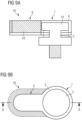
- Fig. 8B is a schematic top view of the locking mechanism 9′′′ according to Fig. 8A in a locking position.
- the locking element 38 comprises a first handle 41 and a second handle 42. Pushing the first handle 41 moves the locking element 38 from the unlocking position of Fig. 8A into the locking position of Fig. 8B . Pushing the second handle 42 moves the locking element 38 back from the locking position into the unlocking position.
- Fig. 9A is a schematic top view of a locking mechanism 44 according to an alternative example not in accordance with the claimed invention.
- the locking mechanism 44 instead of a locking element comprises a flexible buffer element 43 arranged in the second section 8 of the keyhole-shaped recess 6.
- the buffer element is configured flexible and may load the headed bolt 5 once inserted into the second section 8 of the recess 6 with a frictional force to hold the headed bolt 5 in the second section.
- the buffer element is made of flexible material which is fixed, in particular firmly bonded, to the material in which the recess 6 is formed.
- Fig. 9B is a schematic top view of the locking mechanism 44 according to Fig. 9A .
- the buffer element 43 substantially surrounds the second section 8 of the recess 6. In this way, the frictional force can be applied from both sides of the recess to the head 19 of the headed bolt 5.
- Fig. 10A is a schematic top view of a locking mechanism 44' according to a further alternative example not in accordance with the claimed invention in an unlocking position.
- This example basically differs from figures 9A and 9B in that the keyhole shaped recess is formed within a bottom plate 13 of a second housing 3.
- the headed bolt is inserted into the first section 7 of the keyhole shape recess.
- Fig. 10B is a schematic top view of the locking mechanism 44' according to Fig. 10A in a locking position.
- the headed bolt 5 is pushed along the longitudinal axis 29 of the recess 6 from the first section 7 into the second section of the keyhole shaped recess 6.
- the buffer element 43 arranged in the second section 8 has a bell shape. Therefore, and the headed bolt 5 can be inserted with the comparably small pushing force. When pushed into the bell-shaped buffer element 43, the buffer element elastically deforms such that the headed bolt 5 is frictionally held in a locking position.
- Fig. 10C is a schematic longitudinal sectional view of the locking mechanism according to Fig. 10B .
- the head 19 of the bolt 5 is completely surrounded by the buffer element 43 and frictionally held therein by elastic deformation of the buffer element 43.
- the buffer element 43 is preferably formed of a material different from the material in which the recess is formed.
- the recess can be formed in a metal plate and the buffer element 43 can be made of a polymer material, in particular a thermoplastic and/or elastomer material, in order to provide a maximum frictional coefficient.
Landscapes
- Engineering & Computer Science (AREA)
- Microelectronics & Electronic Packaging (AREA)
- General Engineering & Computer Science (AREA)
- Mechanical Engineering (AREA)
- Connection Of Plates (AREA)
Claims (9)
- System (1) zum lösbaren Verbinden eines ersten Vorrichtungsgehäuses (2) mit einem zweiten Vorrichtungsgehäuse (3), umfassend:mindestens drei Anschlusseinheiten (4),wobei die Verbindungseinheiten (4) jeweils zwei Teile umfassen, von denen einer einen Kopfbolzen (5) und der andere eine entsprechende schlüssellochförmige Aussparung (6) umfasst, die zur Aufnahme des Kopfbolzens (5) derart ausgebildet ist, dass der Kopfbolzen (5) in einem ersten Abschnitt (7) in die Aussparung (6) einführbar und in einem zweiten Abschnitt (8) in der Aussparung (6) gehalten ist, so dass der Kopfbolzen (5) und die schlüssellochförmige Aussparung (6) formschlüssig verbunden werden können,wobei mindestens eine der Verbindungseinheiten (4) einen Verriegelungsmechanismus (9'; 9") zum Verriegeln des Bolzens (5) im zweiten Abschnitt (8) der Aussparung (6) umfasst, wobei der Verriegelungsmechanismus (9'; 9") ein bewegliches Verriegelungselement (21; 28) umfasst,der gegenüber dem Kopfbolzen (5) beweglich ist und konfiguriert ist, um den Kopfbolzen (5) im zweiten Abschnitt (8) der Aussparung (6) in einer Verriegelungsposition zu halten,wobei der Verriegelungsmechanismus (9'; 9") eine Verriegelungsnase (24) umfasst, wobei die Verriegelungsnase (24) konfiguriert ist, um den Kopfbolzen (5) im zweiten Abschnitt (8) der Aussparung (6) zu erfassen, wobei die Verriegelungsnase so angeordnet ist, dass der Kopfbolzen beim Einführen in die schlüssellochförmige Aussparung und Bewegen vom ersten Abschnitt in den zweiten Abschnitt automatisch durch das Verriegelungselement verriegelt wird,wobei das Verriegelungselement (21; 28) als quer zur Bolzenachse verschiebbarer Schieber konfiguriert ist,wobei das Verriegelungselement (21; 28) durch ein Federelement (22, 30) derart vorgespannt ist, dass das Verriegelungselement (21; 28) federnd in der Verriegelungsposition gehalten wird, undwobei die Verriegelungsnase (24) an dem Verriegelungselement (21; 28; 38) befestigt oder einstückig mit diesem ausgebildet ist.
- System nach Anspruch 1, wobei der Verriegelungsmechanismus (9'; 9") einen Griff zum Bewegen des Verriegelungselements von der Verriegelungsposition in eine Entriegelungsposition umfasst.
- System nach einem der vorstehenden Ansprüche, wobei die Verriegelungsnase (24) als Rampe oder Nase mit einer ansteigenden Seite (25) und einer Kante (25) ausgebildet ist.
- System nach einem der vorstehenden Ansprüche, wobei der erste Abschnitt (7) der schlüssellochförmigen Aussparung (6) breiter als der zweite Abschnitt (8) und breiter als ein größter hervorstehender Querschnittsteil des Kopfbolzens (5) ist.
- System nach einem der vorstehenden Ansprüche, wobei der zweite Abschnitt (8) der schlüssellochförmigen Aussparung (6) kleiner als der größte hervorstehende Querschnittsteil des Kopfbolzens (5) ist.
- System nach einem der vorstehenden Ansprüche, wobei der Kopfbolzen (5) als Pilzkopfbolzen konfiguriert ist.
- Verbindungsanordnung (20), umfassend ein erstes Vorrichtungsgehäuse (2) und ein zweites Vorrichtungsgehäuse (3), das mit einem lösbaren Verbindungssystem (1) nach einem der vorstehenden Ansprüche mit dem ersten Vorrichtungsgehäuse (2) gekoppelt ist.
- Anordnung nach Anspruch 7, wobei der Bolzen (5) am ersten Vorrichtungsgehäuse (2) befestigt ist.
- Anordnung nach Anspruch 7 oder 8, wobei die schlüssellochförmige Aussparung (6) im zweiten Vorrichtungsgehäuse (3) ausgebildet ist.
Priority Applications (1)
| Application Number | Priority Date | Filing Date | Title |
|---|---|---|---|
| EP18212600.3A EP3668285B1 (de) | 2018-12-14 | 2018-12-14 | System zum lösbaren verbinden eines ersten vorrichtungsgehäuses mit einem zweiten vorrichtungsgehäuse und verbindungsanordnung |
Applications Claiming Priority (1)
| Application Number | Priority Date | Filing Date | Title |
|---|---|---|---|
| EP18212600.3A EP3668285B1 (de) | 2018-12-14 | 2018-12-14 | System zum lösbaren verbinden eines ersten vorrichtungsgehäuses mit einem zweiten vorrichtungsgehäuse und verbindungsanordnung |
Publications (2)
| Publication Number | Publication Date |
|---|---|
| EP3668285A1 EP3668285A1 (de) | 2020-06-17 |
| EP3668285B1 true EP3668285B1 (de) | 2024-09-04 |
Family
ID=64665569
Family Applications (1)
| Application Number | Title | Priority Date | Filing Date |
|---|---|---|---|
| EP18212600.3A Active EP3668285B1 (de) | 2018-12-14 | 2018-12-14 | System zum lösbaren verbinden eines ersten vorrichtungsgehäuses mit einem zweiten vorrichtungsgehäuse und verbindungsanordnung |
Country Status (1)
| Country | Link |
|---|---|
| EP (1) | EP3668285B1 (de) |
Families Citing this family (2)
| Publication number | Priority date | Publication date | Assignee | Title |
|---|---|---|---|---|
| EP4013198A1 (de) * | 2020-12-11 | 2022-06-15 | Hoffman Enclosures, Inc. | Halterung für einen verteiler |
| CN118810534A (zh) * | 2024-09-18 | 2024-10-22 | 宁波信泰机械有限公司 | 一种快换连接组件及电动车 |
Citations (4)
| Publication number | Priority date | Publication date | Assignee | Title |
|---|---|---|---|---|
| US6010306A (en) * | 1997-05-05 | 2000-01-04 | King Of Fans, Inc. | Quick assembly blades for ceiling fans |
| US6196758B1 (en) * | 1998-03-30 | 2001-03-06 | Dane Scarborough | Tool having an accessory receiver |
| EP1105023A1 (de) * | 1999-06-18 | 2001-06-13 | Frank Lodi | Eingebaute sockelunterstützung für bauteile |
| DE10228755A1 (de) * | 2002-06-27 | 2004-01-22 | Siemens Ag | Gehäuse zur Befestigung an einer Wand |
Family Cites Families (3)
| Publication number | Priority date | Publication date | Assignee | Title |
|---|---|---|---|---|
| US3700020A (en) * | 1970-08-24 | 1972-10-24 | Richard M Wallace | Bolt anchor assembly |
| DE2942936A1 (de) * | 1979-10-24 | 1981-05-07 | Robert Bosch Gmbh, 7000 Stuttgart | Auf einem kuehlkoerper mit im wesentlichen ebener oberflaeche angeordnete metallgehaeuse |
| DE19806690A1 (de) * | 1998-02-18 | 1999-09-02 | Daimler Chrysler Ag | Befestigung eines Bauteiles an einem plattenförmigen Tragteil |
-
2018
- 2018-12-14 EP EP18212600.3A patent/EP3668285B1/de active Active
Patent Citations (4)
| Publication number | Priority date | Publication date | Assignee | Title |
|---|---|---|---|---|
| US6010306A (en) * | 1997-05-05 | 2000-01-04 | King Of Fans, Inc. | Quick assembly blades for ceiling fans |
| US6196758B1 (en) * | 1998-03-30 | 2001-03-06 | Dane Scarborough | Tool having an accessory receiver |
| EP1105023A1 (de) * | 1999-06-18 | 2001-06-13 | Frank Lodi | Eingebaute sockelunterstützung für bauteile |
| DE10228755A1 (de) * | 2002-06-27 | 2004-01-22 | Siemens Ag | Gehäuse zur Befestigung an einer Wand |
Also Published As
| Publication number | Publication date |
|---|---|
| EP3668285A1 (de) | 2020-06-17 |
Similar Documents
| Publication | Publication Date | Title |
|---|---|---|
| US11032928B2 (en) | System for releaseably connecting a first device housing with a second device housing and connection arrangement | |
| US8534782B2 (en) | Slide rail assembly | |
| US8408506B2 (en) | Mounting appratus for slide rail | |
| EP3668285A1 (de) | System zum lösbaren verbinden eines ersten vorrichtungsgehäuses mit einem zweiten vorrichtungsgehäuse und verbindungsanordnung | |
| US9635919B2 (en) | Closure device | |
| US20120193489A1 (en) | Mounting apparatus for slide rail | |
| US8454261B2 (en) | Snap-and-click hatrack fastener | |
| US20230024078A1 (en) | A suspension assembly for supporting a vibration sensitive device | |
| US8602674B2 (en) | Device for connecting two components | |
| US20070003390A1 (en) | Pin and grommet fastener with high fastening strength, and airbag attached to vehicle body by such fastener | |
| US20250261755A1 (en) | Wall and ceiling track system for mounting devices | |
| US20110267749A1 (en) | Robust lightweight electronic rack enclosure | |
| US12152627B2 (en) | Fastening device having a base part and a blocking part | |
| US10113317B1 (en) | Apparatus and method for hanging architectural panels with concealed attachment points | |
| US20110255940A1 (en) | Cartridge-type-loading transit case system and method for loading electronic racks in a receiver rack | |
| US20090325046A1 (en) | Battery cover assembly for electronic device | |
| EP3778350B1 (de) | Transportsystem mit zwei transportplattformen und einem verbindungselement | |
| US5031794A (en) | Container for elastic solid material | |
| KR20180115287A (ko) | 휴대용 스테이지 시스템 | |
| CN111824041B (zh) | 用于固定两个元件以允许其预组装的装置 | |
| CN107745869B (zh) | 内卡支撑组件和包装结构 | |
| WO2013166512A1 (en) | Replaceable wafer support backstop | |
| EP2489249A1 (de) | Verbesserte regalsysteme | |
| US20150374122A1 (en) | Accommodating device, segment, and method for forming multiple-stage accommodating portions | |
| CN214730569U (zh) | 组合式收纳箱 |
Legal Events
| Date | Code | Title | Description |
|---|---|---|---|
| PUAI | Public reference made under article 153(3) epc to a published international application that has entered the european phase |
Free format text: ORIGINAL CODE: 0009012 |
|
| STAA | Information on the status of an ep patent application or granted ep patent |
Free format text: STATUS: THE APPLICATION HAS BEEN PUBLISHED |
|
| AK | Designated contracting states |
Kind code of ref document: A1 Designated state(s): AL AT BE BG CH CY CZ DE DK EE ES FI FR GB GR HR HU IE IS IT LI LT LU LV MC MK MT NL NO PL PT RO RS SE SI SK SM TR |
|
| AX | Request for extension of the european patent |
Extension state: BA ME |
|
| STAA | Information on the status of an ep patent application or granted ep patent |
Free format text: STATUS: REQUEST FOR EXAMINATION WAS MADE |
|
| 17P | Request for examination filed |
Effective date: 20200731 |
|
| RBV | Designated contracting states (corrected) |
Designated state(s): AL AT BE BG CH CY CZ DE DK EE ES FI FR GB GR HR HU IE IS IT LI LT LU LV MC MK MT NL NO PL PT RO RS SE SI SK SM TR |
|
| STAA | Information on the status of an ep patent application or granted ep patent |
Free format text: STATUS: EXAMINATION IS IN PROGRESS |
|
| 17Q | First examination report despatched |
Effective date: 20210331 |
|
| P01 | Opt-out of the competence of the unified patent court (upc) registered |
Effective date: 20230525 |
|
| GRAP | Despatch of communication of intention to grant a patent |
Free format text: ORIGINAL CODE: EPIDOSNIGR1 |
|
| STAA | Information on the status of an ep patent application or granted ep patent |
Free format text: STATUS: GRANT OF PATENT IS INTENDED |
|
| INTG | Intention to grant announced |
Effective date: 20240426 |
|
| GRAS | Grant fee paid |
Free format text: ORIGINAL CODE: EPIDOSNIGR3 |
|
| GRAA | (expected) grant |
Free format text: ORIGINAL CODE: 0009210 |
|
| STAA | Information on the status of an ep patent application or granted ep patent |
Free format text: STATUS: THE PATENT HAS BEEN GRANTED |
|
| AK | Designated contracting states |
Kind code of ref document: B1 Designated state(s): AL AT BE BG CY CZ DE DK EE ES FI FR GB GR HR HU IS IT LT LU LV MC MK MT NL NO PL PT RO RS SE SI SK SM TR |
|
| RBV | Designated contracting states (corrected) |
Designated state(s): AL AT BE BG CY CZ DE DK EE ES FI FR GB GR HR HU IS IT LT LU LV MC MK MT NL NO PL PT RO RS SE SI SK SM TR |
|
| REG | Reference to a national code |
Ref country code: GB Ref legal event code: FG4D |
|
| REG | Reference to a national code |
Ref country code: DE Ref legal event code: R096 Ref document number: 602018073884 Country of ref document: DE |
|
| REG | Reference to a national code |
Ref country code: LT Ref legal event code: MG9D |
|
| REG | Reference to a national code |
Ref country code: NL Ref legal event code: MP Effective date: 20240904 |
|
| PG25 | Lapsed in a contracting state [announced via postgrant information from national office to epo] |
Ref country code: NO Free format text: LAPSE BECAUSE OF FAILURE TO SUBMIT A TRANSLATION OF THE DESCRIPTION OR TO PAY THE FEE WITHIN THE PRESCRIBED TIME-LIMIT Effective date: 20241204 |
|
| PG25 | Lapsed in a contracting state [announced via postgrant information from national office to epo] |
Ref country code: FI Free format text: LAPSE BECAUSE OF FAILURE TO SUBMIT A TRANSLATION OF THE DESCRIPTION OR TO PAY THE FEE WITHIN THE PRESCRIBED TIME-LIMIT Effective date: 20240904 Ref country code: GR Free format text: LAPSE BECAUSE OF FAILURE TO SUBMIT A TRANSLATION OF THE DESCRIPTION OR TO PAY THE FEE WITHIN THE PRESCRIBED TIME-LIMIT Effective date: 20241205 Ref country code: PL Free format text: LAPSE BECAUSE OF FAILURE TO SUBMIT A TRANSLATION OF THE DESCRIPTION OR TO PAY THE FEE WITHIN THE PRESCRIBED TIME-LIMIT Effective date: 20240904 |
|
| PG25 | Lapsed in a contracting state [announced via postgrant information from national office to epo] |
Ref country code: BG Free format text: LAPSE BECAUSE OF FAILURE TO SUBMIT A TRANSLATION OF THE DESCRIPTION OR TO PAY THE FEE WITHIN THE PRESCRIBED TIME-LIMIT Effective date: 20240904 |
|
| PG25 | Lapsed in a contracting state [announced via postgrant information from national office to epo] |
Ref country code: LV Free format text: LAPSE BECAUSE OF FAILURE TO SUBMIT A TRANSLATION OF THE DESCRIPTION OR TO PAY THE FEE WITHIN THE PRESCRIBED TIME-LIMIT Effective date: 20240904 |
|
| PG25 | Lapsed in a contracting state [announced via postgrant information from national office to epo] |
Ref country code: HR Free format text: LAPSE BECAUSE OF FAILURE TO SUBMIT A TRANSLATION OF THE DESCRIPTION OR TO PAY THE FEE WITHIN THE PRESCRIBED TIME-LIMIT Effective date: 20240904 |
|
| PG25 | Lapsed in a contracting state [announced via postgrant information from national office to epo] |
Ref country code: ES Free format text: LAPSE BECAUSE OF FAILURE TO SUBMIT A TRANSLATION OF THE DESCRIPTION OR TO PAY THE FEE WITHIN THE PRESCRIBED TIME-LIMIT Effective date: 20240904 Ref country code: RS Free format text: LAPSE BECAUSE OF FAILURE TO SUBMIT A TRANSLATION OF THE DESCRIPTION OR TO PAY THE FEE WITHIN THE PRESCRIBED TIME-LIMIT Effective date: 20241204 |
|
| PG25 | Lapsed in a contracting state [announced via postgrant information from national office to epo] |
Ref country code: RS Free format text: LAPSE BECAUSE OF FAILURE TO SUBMIT A TRANSLATION OF THE DESCRIPTION OR TO PAY THE FEE WITHIN THE PRESCRIBED TIME-LIMIT Effective date: 20241204 Ref country code: PL Free format text: LAPSE BECAUSE OF FAILURE TO SUBMIT A TRANSLATION OF THE DESCRIPTION OR TO PAY THE FEE WITHIN THE PRESCRIBED TIME-LIMIT Effective date: 20240904 Ref country code: NO Free format text: LAPSE BECAUSE OF FAILURE TO SUBMIT A TRANSLATION OF THE DESCRIPTION OR TO PAY THE FEE WITHIN THE PRESCRIBED TIME-LIMIT Effective date: 20241204 Ref country code: LV Free format text: LAPSE BECAUSE OF FAILURE TO SUBMIT A TRANSLATION OF THE DESCRIPTION OR TO PAY THE FEE WITHIN THE PRESCRIBED TIME-LIMIT Effective date: 20240904 Ref country code: HR Free format text: LAPSE BECAUSE OF FAILURE TO SUBMIT A TRANSLATION OF THE DESCRIPTION OR TO PAY THE FEE WITHIN THE PRESCRIBED TIME-LIMIT Effective date: 20240904 Ref country code: GR Free format text: LAPSE BECAUSE OF FAILURE TO SUBMIT A TRANSLATION OF THE DESCRIPTION OR TO PAY THE FEE WITHIN THE PRESCRIBED TIME-LIMIT Effective date: 20241205 Ref country code: FI Free format text: LAPSE BECAUSE OF FAILURE TO SUBMIT A TRANSLATION OF THE DESCRIPTION OR TO PAY THE FEE WITHIN THE PRESCRIBED TIME-LIMIT Effective date: 20240904 Ref country code: ES Free format text: LAPSE BECAUSE OF FAILURE TO SUBMIT A TRANSLATION OF THE DESCRIPTION OR TO PAY THE FEE WITHIN THE PRESCRIBED TIME-LIMIT Effective date: 20240904 Ref country code: BG Free format text: LAPSE BECAUSE OF FAILURE TO SUBMIT A TRANSLATION OF THE DESCRIPTION OR TO PAY THE FEE WITHIN THE PRESCRIBED TIME-LIMIT Effective date: 20240904 |
|
| REG | Reference to a national code |
Ref country code: AT Ref legal event code: MK05 Ref document number: 1721769 Country of ref document: AT Kind code of ref document: T Effective date: 20240904 |
|
| PG25 | Lapsed in a contracting state [announced via postgrant information from national office to epo] |
Ref country code: NL Free format text: LAPSE BECAUSE OF FAILURE TO SUBMIT A TRANSLATION OF THE DESCRIPTION OR TO PAY THE FEE WITHIN THE PRESCRIBED TIME-LIMIT Effective date: 20240904 |
|
| PG25 | Lapsed in a contracting state [announced via postgrant information from national office to epo] |
Ref country code: PT Free format text: LAPSE BECAUSE OF FAILURE TO SUBMIT A TRANSLATION OF THE DESCRIPTION OR TO PAY THE FEE WITHIN THE PRESCRIBED TIME-LIMIT Effective date: 20250106 Ref country code: IS Free format text: LAPSE BECAUSE OF FAILURE TO SUBMIT A TRANSLATION OF THE DESCRIPTION OR TO PAY THE FEE WITHIN THE PRESCRIBED TIME-LIMIT Effective date: 20250104 |
|
| PG25 | Lapsed in a contracting state [announced via postgrant information from national office to epo] |
Ref country code: RO Free format text: LAPSE BECAUSE OF FAILURE TO SUBMIT A TRANSLATION OF THE DESCRIPTION OR TO PAY THE FEE WITHIN THE PRESCRIBED TIME-LIMIT Effective date: 20240904 Ref country code: SM Free format text: LAPSE BECAUSE OF FAILURE TO SUBMIT A TRANSLATION OF THE DESCRIPTION OR TO PAY THE FEE WITHIN THE PRESCRIBED TIME-LIMIT Effective date: 20240904 |
|
| PG25 | Lapsed in a contracting state [announced via postgrant information from national office to epo] |
Ref country code: EE Free format text: LAPSE BECAUSE OF FAILURE TO SUBMIT A TRANSLATION OF THE DESCRIPTION OR TO PAY THE FEE WITHIN THE PRESCRIBED TIME-LIMIT Effective date: 20240904 Ref country code: AT Free format text: LAPSE BECAUSE OF FAILURE TO SUBMIT A TRANSLATION OF THE DESCRIPTION OR TO PAY THE FEE WITHIN THE PRESCRIBED TIME-LIMIT Effective date: 20240904 |
|
| PG25 | Lapsed in a contracting state [announced via postgrant information from national office to epo] |
Ref country code: CZ Free format text: LAPSE BECAUSE OF FAILURE TO SUBMIT A TRANSLATION OF THE DESCRIPTION OR TO PAY THE FEE WITHIN THE PRESCRIBED TIME-LIMIT Effective date: 20240904 |
|
| PG25 | Lapsed in a contracting state [announced via postgrant information from national office to epo] |
Ref country code: IT Free format text: LAPSE BECAUSE OF FAILURE TO SUBMIT A TRANSLATION OF THE DESCRIPTION OR TO PAY THE FEE WITHIN THE PRESCRIBED TIME-LIMIT Effective date: 20240904 Ref country code: SK Free format text: LAPSE BECAUSE OF FAILURE TO SUBMIT A TRANSLATION OF THE DESCRIPTION OR TO PAY THE FEE WITHIN THE PRESCRIBED TIME-LIMIT Effective date: 20240904 |
|
| REG | Reference to a national code |
Ref country code: DE Ref legal event code: R097 Ref document number: 602018073884 Country of ref document: DE |
|
| PG25 | Lapsed in a contracting state [announced via postgrant information from national office to epo] |
Ref country code: MC Free format text: LAPSE BECAUSE OF FAILURE TO SUBMIT A TRANSLATION OF THE DESCRIPTION OR TO PAY THE FEE WITHIN THE PRESCRIBED TIME-LIMIT Effective date: 20240904 |
|
| PG25 | Lapsed in a contracting state [announced via postgrant information from national office to epo] |
Ref country code: DK Free format text: LAPSE BECAUSE OF FAILURE TO SUBMIT A TRANSLATION OF THE DESCRIPTION OR TO PAY THE FEE WITHIN THE PRESCRIBED TIME-LIMIT Effective date: 20240904 |
|
| PLBE | No opposition filed within time limit |
Free format text: ORIGINAL CODE: 0009261 |
|
| STAA | Information on the status of an ep patent application or granted ep patent |
Free format text: STATUS: NO OPPOSITION FILED WITHIN TIME LIMIT |
|
| 26N | No opposition filed |
Effective date: 20250605 |
|
| PG25 | Lapsed in a contracting state [announced via postgrant information from national office to epo] |
Ref country code: LU Free format text: LAPSE BECAUSE OF NON-PAYMENT OF DUE FEES Effective date: 20241214 |
|
| PG25 | Lapsed in a contracting state [announced via postgrant information from national office to epo] |
Ref country code: SE Free format text: LAPSE BECAUSE OF FAILURE TO SUBMIT A TRANSLATION OF THE DESCRIPTION OR TO PAY THE FEE WITHIN THE PRESCRIBED TIME-LIMIT Effective date: 20240904 |
|
| REG | Reference to a national code |
Ref country code: BE Ref legal event code: MM Effective date: 20241231 |
|
| PG25 | Lapsed in a contracting state [announced via postgrant information from national office to epo] |
Ref country code: BE Free format text: LAPSE BECAUSE OF NON-PAYMENT OF DUE FEES Effective date: 20241231 |
|
| PGFP | Annual fee paid to national office [announced via postgrant information from national office to epo] |
Ref country code: GB Payment date: 20251218 Year of fee payment: 8 |
|
| PGFP | Annual fee paid to national office [announced via postgrant information from national office to epo] |
Ref country code: FR Payment date: 20251217 Year of fee payment: 8 |
|
| PGFP | Annual fee paid to national office [announced via postgrant information from national office to epo] |
Ref country code: DE Payment date: 20251222 Year of fee payment: 8 |