EP3668778B1 - Geschlossene konstruktionskomponente und verfahren zur herstellung davon - Google Patents
Geschlossene konstruktionskomponente und verfahren zur herstellung davon Download PDFInfo
- Publication number
- EP3668778B1 EP3668778B1 EP18755819.2A EP18755819A EP3668778B1 EP 3668778 B1 EP3668778 B1 EP 3668778B1 EP 18755819 A EP18755819 A EP 18755819A EP 3668778 B1 EP3668778 B1 EP 3668778B1
- Authority
- EP
- European Patent Office
- Prior art keywords
- longitudinal wall
- elongated base
- base composite
- flat top
- structural component
- Prior art date
- Legal status (The legal status is an assumption and is not a legal conclusion. Google has not performed a legal analysis and makes no representation as to the accuracy of the status listed.)
- Active
Links
Images



Classifications
-
- B—PERFORMING OPERATIONS; TRANSPORTING
- B62—LAND VEHICLES FOR TRAVELLING OTHERWISE THAN ON RAILS
- B62D—MOTOR VEHICLES; TRAILERS
- B62D29/00—Superstructures, understructures, or sub-units thereof, characterised by the material thereof
- B62D29/04—Superstructures, understructures, or sub-units thereof, characterised by the material thereof predominantly of synthetic material
-
- B—PERFORMING OPERATIONS; TRANSPORTING
- B60—VEHICLES IN GENERAL
- B60R—VEHICLES, VEHICLE FITTINGS, OR VEHICLE PARTS, NOT OTHERWISE PROVIDED FOR
- B60R19/00—Wheel guards; Radiator guards, e.g. grilles; Obstruction removers; Fittings damping bouncing force in collisions
- B60R19/02—Bumpers, i.e. impact receiving or absorbing members for protecting vehicles or fending off blows from other vehicles or objects
- B60R19/18—Bumpers, i.e. impact receiving or absorbing members for protecting vehicles or fending off blows from other vehicles or objects characterised by the cross-section; Means within the bumper to absorb impact
-
- B—PERFORMING OPERATIONS; TRANSPORTING
- B62—LAND VEHICLES FOR TRAVELLING OTHERWISE THAN ON RAILS
- B62D—MOTOR VEHICLES; TRAILERS
- B62D25/00—Superstructure or monocoque structure sub-units; Parts or details thereof not otherwise provided for
-
- B—PERFORMING OPERATIONS; TRANSPORTING
- B29—WORKING OF PLASTICS; WORKING OF SUBSTANCES IN A PLASTIC STATE IN GENERAL
- B29L—INDEXING SCHEME ASSOCIATED WITH SUBCLASS B29C, RELATING TO PARTICULAR ARTICLES
- B29L2031/00—Other particular articles
- B29L2031/30—Vehicles, e.g. ships or aircraft, or body parts thereof
- B29L2031/3044—Bumpers
Definitions
- the present invention is directed to a closed structural component and process for preparing the same.
- Structural components find wide application as reinforcement materials in the automobile industry.
- a typical motor vehicle is assembled by aligning and fastening numerous components such as a roof cross member, cross beam, front end, floor, pillars, roof frame, seat and many more.
- numerous components such as a roof cross member, cross beam, front end, floor, pillars, roof frame, seat and many more.
- the automobile industry has endeavored to provide vehicle structures that are capable of absorbing or deflecting shocks or stresses on the passenger cell.
- structures are employed, for example, that reinforce or stiffen the frame surrounding the passenger cell by means of structural components.
- US 2008/0217960 A1 describes one such support that possesses flow channels in the direction of its longitudinal axis.
- the support additionally possesses external surfaces that are offset to each other in the direction of the longitudinal axis as well as a lateral external surface. These external surfaces are provided with a layer of a thermally expansible and curable composition.
- Reinforcing components of this type are suitable for stiffening and/or reinforcing hollow supports, such as the A-, B- or C-pillars, the roof edges or the rocker panels of vehicles, especially passenger cars.
- US 8,047,603 B2 discloses a plastic crush countermeasure for motor vehicles that includes a plastic insert and a reinforcement structure that provides impact and/or reinforcement characteristics and an attachment interface to the vehicle in a lighter weight structure.
- the crush countermeasure provides a lightweight crush systern that provides comparable protection to current metal crush countermeasures using, in part, a plastic material. As such, the overall weight of a vehicle is reduced without any reduction in safety to passengers.
- Another US 2006/0181089 A1 describes an impact beam comprising a metal crosspiece and reinforcement ribs made of a plastic material and overmolded onto the metal crosspiece.
- WO 2007/082677 A1 describes hollow profiles which are reinforced with ribbed structures in which the ribs run perpendicular to the axis of the hollow profile and the ends of the ribs are provided with heat activatable adhesive material which may be expandable activated to bond the ends of the ribs to the inner surface of the hollow profile.
- EP 2 636 578 A2 describes an injection molded structural component with a hollow structural section, said hollow structural section comprising a section body having a cavity with an opening, a section lid secured to said section body via a hinge-folded onto said opening and a means fastening the section lid to the section body such that the hollow structural section withstands dynamical load.
- the prior art structural components have several limitations. These components are unable to withstand buckling due to high load and stress, thereby reducing the buckling load. Moreover, it is also desirable to provide a structural component which, being light in weight, is capable of withstanding or deflecting the torsion, bending and crushing due to sudden impact or increase in load. Further, a structural component which is easily manufactured and used without any additional processing steps is a challenge to obtain. Also, the existence of an adhesive or a fastening means within the component results in loss of structural area which further results in lesser reinforcement and reduced load bearing capability.
- a closed structural component (300) comprising an elongated base composite (100) comprising a first longitudinal wall (101) and a second longitudinal wall (102) each having an edge (103), wherein the first and the second longitudinal walls (101, 102) are placed opposite to one another and disposed on a bottom (104), a plurality of reinforcement ribs (105) connected at each end to each of the first longitudinal wall (101) and the second longitudinal (102) and dispersed on the bottom (104), and a flat top (200) disposed onto the edge (103) of the first and the second longitudinal walls (101, 102) of the elongated base composite (100), wherein a flat top (200) is integrally molded to an elongated based composite (100) is capable of withstanding buckling due to high load and stress, is capable of withstanding or deflecting the torsion, bending and crushing due to sudden impact or increase in load, is easier to manufacture and use without any additional processing steps and is completely reinforced without any loss in load bearing capability for application in areas such as,
- a closed structural component (300) which comprises:
- the presently claimed invention is directed to a process for preparing a closed structural component (300), comprising the steps of:
- the presently claimed invention is directed to a process for preparing a closed structural component (300), comprising the steps of:
- the presently claimed invention is directed to a closed structural component (300) obtained by the above processes.
- the presently claimed invention is directed to the use of the above closed structural component (300) in automotive industry as an insert or for home and decorative purposes as an insert in furniture.
- a group is defined to comprise at least a certain number of embodiments, this is meant to also encompass a group which preferably consists of these embodiments only.
- the terms “first”, “second”, “third” or “(a)”, “(b)”, “(c)”, “(d)” etc. and the like in the description and in the claims, are used for distinguishing between similar elements and not necessarily for describing a sequential or chronological order. It is to be understood that the terms so used are interchangeable under appropriate circumstances and that the embodiments of the presently claimed invention described herein are capable of operation in other sequences than described or illustrated herein.
- first”, “second”, “third” or “(A)”, “(B)” and “(C)” or “(a)”, “(b)”, “(c)”, “(d)”, “i”, “ii” etc. relate to steps of a method or use or assay there is no time or time interval coherence between the steps, that is, the steps may be carried out simultaneously or there may be time intervals of seconds, minutes, hours, days, weeks, months or even years between such steps, unless otherwise indicated in the application as set forth herein above or below.
- ranges defined throughout the specification include the end values as well, i.e. a range of 1 to 10 implies that both 1 and 10 are included in the range.
- the individual embodiments may be described as a process which is depicted as a flowchart, a flow diagram, a data flow diagram, a structure diagram, or a block diagram.
- a flowchart may describe the operations as a sequential process, many of the operations can be performed in parallel or concurrently.
- the order of the operations may be re-arranged.
- a process may be terminated when its operations are completed, but could have additional steps not discussed or included in a figure.
- not all operations in any particularly described process may occur in all embodiments.
- a process may correspond to a method, a function, a procedure, etc.
- embodiments of the invention may be implemented, at least in part, either manually or automatically.
- Manual or automatic implementations may be executed, or at least assisted, through the use of machines, hardware, software, firmware, middleware, microcode, hardware description languages, or any combination thereof.
- the closed structural composite (300) comprises an elongated base composite (100) and a flat top (200), as shown in Fig. 1 .
- the elongated base composite (100) forms the base, while the flat top (200) closes the said base composite to form a closed structural composite (300).
- the flat top (200) is integrally molded to the elongated base composite (100).
- integrally molded means that the flat top (200) and the elongated base composite (100) are part of one whole singularly formed or molded component.
- the elongated base composite (100) comprises a first longitudinal wall (101) and a second longitudinal wall (102) each having an edge (103).
- the first and the second longitudinal walls (101, 102) are placed opposite to one another and disposed on a bottom (104) of the elongated base composite (100).
- the first longitudinal wall (101) and the second longitudinal wall (102) are placed at a constant separation.
- the relative arrangement of the first and second longitudinal walls (101, 102) depends on the desired geometry. Alternatively, they may also be placed at variable separation.
- a plurality of reinforcement ribs (105) is connected at each end to each of the first longitudinal wall (101) and the second longitudinal wall (102) and dispersed on the bottom (104) of the elongated base composite (100).
- the said reinforcement ribs (105) connect the first and the second longitudinal walls (101, 102), thereby forming a reinforcement structure which provides strength to the overall closed structural component (300).
- the elongated base composite (100) further comprises a plurality of longitudinal reinforcement ribs (106) dispersed between two or more reinforcement ribs (105).
- the plurality of longitudinal reinforcement ribs (106) is disposed on the bottom (104) of the elongated base composite (100) and are located at a constant or variable separation from the first and the second longitudinal walls (101, 102).
- the plurality of longitudinal reinforcement ribs (106) is disposed on the bottom (104) of the elongated base composite (100) and are located at a constant separation from the first and the second longitudinal walls (101, 102).
- the plurality of longitudinal reinforcement ribs (106) further support the reinforcement ribs (105) and strengthen the overall closed structural component (300).
- the closed structural component (300) may be obtained in segments, it is preferred that the final closed structural component (300) be of unitary construction made from a durable material.
- the closed structural component (300) comprises of the flat top (200) integrally molded to the first longitudinal wall (101) or the second longitudinal wall (102) of the elongated base composite (100).
- the flat top (200) is integrally molded to the first longitudinal wall (101).
- the flat top (200) is integrally molded to the second longitudinal wall (102).
- thermoplastic composite material materials that are useful for making the component (300) include, but are not limited to, thermoplastic composite material. Accordingly, the term “composite” as used hereinabove and hereinafter, refers to at least one thermoplastic composite material. Although, other materials can also be used for this purpose, thermoplastic composite materials have been chosen for the present invention due to their enhanced performance characteristic over a wide range of temperature and pressure conditions.
- the at least one thermoplastic composite material comprises a plurality of reinforcing fiber bonded together with a thermoplastic material. That is, to say, that the plurality of reinforcing fibers is impregnated on the surface of the thermoplastic material and strongly bond therewith. This results in the overall composite achieving properties better than the material itself.
- the choice of such reinforcing fiber is based on the physical characteristics desired in the component.
- the reinforcing fiber comprises one or more of metal fiber, metalized inorganic fiber, metalized synthetic fiber, glass fiber, polyester fiber, polyamide fiber, graphite fiber, carbon fiber, ceramic fiber, mineral fiber, basalt fiber, inorganic fiber, aramid fiber, kenaf fiber, jute fiber, flax fiber, hemp fiber, cellulosic fiber, sisal fiber and coir fiber.
- the reinforcing fiber comprises one or more of metal fiber, metalized inorganic fiber, metalized synthetic fiber, glass fiber, polyester fiber, polyamide fiber, graphite fiber, carbon fiber, ceramic fiber, mineral fiber, basalt fiber and inorganic fiber.
- the reinforcing fiber comprises one or more of glass fiber, polyester fiber, polyamide fiber, graphite fiber, carbon fiber, ceramic fiber and mineral fiber.
- the said thermoplastic material of the at least one thermoplastic composite material comprises one or more of polyolefins, polyamides, polystyrene, acrylonitrylstyrene, butadiene, polyesters, polybutyleneterachlorate, polyvinyl chloride, polyphenylene ether, polyphenylene oxide, polyether imide, polycarbonates, polyestercarbonates, acrylonitrile-butylacrylate-styrene polymers, polybutyleneterephthalate and polyethyleneteraphthalate.
- the thermoplastic material comprises one or more of polyolefins, polyamides, polystyrene, acrylonitrylstyrene, butadiene, polyesters, polybutyleneterachlorate, polyvinyl chloride, polyphenylene ether, polyphenylene oxide, polyether imide, polycarbonates, polyestercarbonates and acrylonitrile-butylacrylate-styrene polymers.
- it comprises one or more of polyolefins, polyamides, polystyrene, acrylonitrylstyrene, butadiene, polyesters, polybutyleneterachlorate, polyvinyl chloride and polyphenylene ether.
- the thermoplastic material is a polyamide comprising of nylon-6, nylon-6,6 or mixture thereof. These materials may be obtained commercially such as, but not limited to, Ultramid® from BASF.
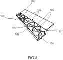
- the plurality of reinforcement ribs (105), as described hereinabove, may have any configuration inside the elongated base composite (100). However, the choice of such configuration depends upon the area of application of the closed structural component (300). Typically, the plurality of reinforcement ribs (105) has a X-shaped configuration, ring-shaped configuration, triangular configuration, inverted triangle configuration and other polygonal configuration. Every configuration has a different structural role in the closed structural composite (300). For instance, the plurality of reinforcement ribs (105) having a X-shaped configuration find application in areas of high torsional loading, as shown in Figs. 2 , 3 and 4 .
- the closed structural component (300) may have any dimension depending upon its application. For instance, it can have a length in the range of greater or equal to 0.1 m to lower or equal to 1.5 m, breadth in the range of greater or equal to 0.01 m to lower or equal to 0.2 m and height in the range of greater or equal to 0.01 m to lower or equal to 0.1 m.
- length it is referred to the dimension in the longitudinal direction.
- breadth corresponds to the dimension perpendicular to the longitudinal direction.
- the term “height” refers to the dimension perpendicular to the plane created by the surface having dimensions of length and breadth i.e. the surface perpendicular to bottom (104) of the elongated base composite (100).
- a process for preparing the closed structural component (300) comprises the steps of:
- the step (A) of the process described hereinabove requires thermoforming of the at least one thermoplastic composite material.
- the at least one thermoplastic composite material is heated to a temperature in the range of greater or equal to Tm to lower or equal to Tm+30°C, wherein Tm is the melt temperature of the at least one thermoplastic composite material determined according to ISO 3146:2000. This is achieved by techniques such as, but not limited to, infrared heater, contact heater and hot air heater.
- the at least one thermoplastic composite material upon heating is molded to a desired geometry. The choice of such a geometry depends on the application of the closed structural component (300). A person skilled in the art is well aware of different heating techniques and geometries that can be used to form the desired closed structural component (300).
- a mold is selected such that the resulting elongated base composite (100) comprises the first longitudinal wall (101), the second longitudinal wall (102) and the bottom (104), wherein the first and the second longitudinal walls (101, 102) are placed opposite to one another and disposed on the bottom (104), and wherein the flat top (200) is disposed on the edge (103) of the first longitudinal wall at an angle theta ( ⁇ ) which is in the range of greater or equal to 0 degrees to lower or equal to 90 degrees.
- the flat top (200) disposed on the edge (103) of the first longitudinal wall (101) of the elongated base composite (100) forms an extended first longitudinal wall.
- the flat top (200) subtends an angle ⁇ from the horizontal, such that ⁇ is in the range of greater or equal to 0 degrees to lower or equal to 90 degrees.
- ⁇ is in the range of greater or equal to 0 degrees to lower or equal to 90 degrees.
- horizontal it is referred to the plane surface parallel to the bottom (104) of the elongated base composite (100) or the bottom (104) itself.
- the flat top (200) forming the extended first longitudinal wall is parallel to the bottom (104) to resemble a pan-like shape, as shown by continuous lines in the elongated base composite (100).
- the flat top (200) forming the extended first longitudinal wall is perpendicular to the bottom (104) to resemble a J-like shape, as depicted by the dotted lines in the elongated base composite (100).
- injection molding process As described in step (B).
- injection molding technique is well known to a person skilled in the art and accordingly the choice of different molds for the said process along with the typical process conditions can be made depending upon the desired geometry of the final closed structural component to be obtained.
- This technique is the most common method for producing articles or parts made of plastic, for e.g. the at least one thermoplastic composite material, as described hereinabove.
- the process includes the injection or forcing of heated molten plastic into a mold which is in the form of the part to be made. Upon cooling and solidification, the part is ejected and the process continues.
- the injection molding process can produce an infinite variety of part designs containing an equally infinite variety of details such as threads, springs, and hinges and all in a single molding operation.
- the injection system mechanism may be of the reciprocating screw type or, less frequently, the two-stage screw type. Also included is a hopper, a heated injection barrel encasing the screw, a hydraulic motor, and an injection cylinder.
- the system's function is to heat the plastic to the proper viscosity and inject it into the mold. As the plastic enters the injection barrel, it is moved forward by the rotation of the screw. As this movement occurs, the plastic is melted by frictional heat and supplementary heating of the barrel encasing the screw.
- the screw has three distinct zones which further processes the plastic prior to actual injection.
- Injection is achieved through an arrangement of valves and a nozzle, all acted upon by the screw and the hydraulic pump that pushes the plastic into the mold.
- the pressure during injection molding is in the range of greater or equal to 130 MPa to lower or equal to 210 MPa.
- the temperature conditions are in the range of greater or equal to 200°C to lower or equal to 400°C.
- the mold determines the part's shape, acts as a heat sink to cool the part, is made to vent trapped air and gases, and, finally, ejects the finished part. Molds are most often made of special molding steel. Other mold materials include beryllium copper, stainless steel, aluminum, brass and kirksite. Molds are manufactured by machining, EDM or casting. The finished mold surfaces are often polished and coated to resist wear and aid in part ejection.
- injection molding of the elongated base composite (100) is done with the at least one thermoplastic composite material to obtain a plurality of reinforcement ribs (105) connected at each end to each of the first longitudinal wall (101) and the second longitudinal wall (102) and dispersed on the bottom (104) in the elongated base composite (100). Accordingly, when the at least one thermoplastic composite material is injected in the machine, the resulting product obtained thereby is an elongated base composite (100) comprising the features described hereinabove.
- pressing it is referred to subjecting the elongated base composite (100) to conditions of pressure and temperature to obtain the closed structural component (300).
- the flat top (200) which is disposed on the edge (103) of the first longitudinal wall at an angle theta ( ⁇ ) which is in the range of greater or equal to 0 degrees to lower or equal to 90 degrees, is pressed onto the edge (103) of the second longitudinal wall (102) of the elongated base composite (100) of step (B) to obtain a closed structural component (300).
- the typical process conditions for pressing is well known to a person skilled in the art. However, for the purpose of the present invention, a temperature in the vicinity of the melting temperature of the at least one thermoplastic composite material is maintained.
- the pressing leads to the at least one thermoplastic composite material getting adhered onto the elongated base composite (100).
- the adhesive properties of the at least one thermoplastic composite material provides for the further enhancement in the physical characteristics of the closed structural component (300) obtained thereafter.
- the elongated base composite (100) obtained in step (A) has an edge (103) on each of the first and the second longitudinal walls (101, 102), as shown in the figures.
- the flat top (200) can be thermoformed on one of the said edge (103) on any one of the first or second longitudinal wall (101, 102).
- the flat top (200) closes the elongated base composite (100) on the top, thereby forming a closed structural component (300).
- the flat top (200) is disposed on the edge (103) of the first longitudinal wall (101), as shown in Figs. 2 & 3 .
- the flat top (200) can be disposed onto the edge (103) of the second longitudinal wall (102) and then pressed towards the edge (103) of the first longitudinal wall (101) after injection molding the elongated base composite (100) with the plurality of reinforcement ribs (105).
- a temperature in the range of greater or equal to Tm to lower or equal to Tm+30°C is provided, wherein Tm is the melt temperature of the at least one thermoplastic composite material determined according to ISO 3146:2000.
- Tm is the melt temperature of the at least one thermoplastic composite material determined according to ISO 3146:2000.
- the elongated base composite (100) obtained in step (B) further comprises a plurality of longitudinal reinforcement ribs (106) dispersed between two or more reinforcement ribs (105).
- the plurality of longitudinal reinforcement ribs (106) is disposed on the bottom (104) of the elongated base composite (100), as described hereinabove.
- the flat top (200) is integrally molded to the first longitudinal wall (101) or the second longitudinal wall (102) of the elongated base composite. Said otherwise, no adhesive or fastening means is present between the flat top (200) and the elongated top composite (100).
- the absence of any adhesive or fastening means results in complete reinforcement of the closed structural component (300) due to availability of additional structural area.
- complete reinforcement here refers to the closed structural component (300) having continuous fibers of the reinforcing fibers on the additional structural area. That is, to say, that the continuous fibers are dispersed on the edges (103) of the first and second longitudinal wall (101, 102), which form the additional area.
- the presence of adhesive or fastening means would have no fibers in these areas. This benefits the component (300) by enhancing the load bearing capacity and therefore, the present component (300) does not results in any loss in its load bearing capability.
- the closed structural component (300) can be obtained by a process comprising the steps of:
- the at least one thermoplastic composite is injection molded in a mold to directly obtain an elongated base composite (100) without performing the step of thermoforming.
- the elongated base composite (100) comprises a first longitudinal wall (101) and a second longitudinal wall (102) each having an edge (103).
- the first and the second longitudinal walls (101, 102) are placed opposite to one another and disposed on a bottom (104).
- a plurality of reinforcement ribs (105) connected at each end to each of the first longitudinal wall (101) and the second longitudinal wall (102) and dispersed on the bottom (104).
- a flat top (200) is disposed on the edge of the first longitudinal wall (101) of the elongated base composite (100) at an angle theta ( ⁇ ) which is in the range of greater or equal to 0 degrees to lower or equal to 90 degrees.
- the flat top (200) when disposed on the edge (103) of the first longitudinal wall (101) of the elongated base composite (100), forms an extended first longitudinal wall.
- the flat top (200) subtends an angle ⁇ from the horizontal, such that ⁇ is in the range of greater or equal to 0 degrees to lower or equal to 90 degrees.
- ⁇ is in the range of greater or equal to 0 degrees to lower or equal to 90 degrees.
- the flat top (200) forming the extended first longitudinal wall is parallel to the bottom (104) to resemble a pan-like shape, as shown in Fig. 2 and as depicted by the continuous lines in Fig. 4 .
- the flat top (200) forming the extended first longitudinal wall is perpendicular to the bottom (104) to resemble a J-like shape, as shown in Fig. 3 and as depicted by the dotted lines in Fig. 4 .
- the elongated base composite (100), as described hereinabove, is obtained as a single component in the injection molding process in step (A').
- the flat top (200), represented by either the continuous lines or the dotted lines in Fig. 4 , is then pressed in step (B') by means of mechanical press or manually by hand towards the edge (103) of the second longitudinal wall (102) to form a flat top (200) disposed on the edge (103) of each of the first and the second longitudinal walls (101, 102), thereby obtaining a closed structural component (300).
- a temperature in the range of greater or equal to Tm to lower or equal to Tm+30°C is provided, wherein Tm is the melt temperature of the at least one thermoplastic composite material determined according to ISO 3146:2000.
- Tm is the melt temperature of the at least one thermoplastic composite material determined according to ISO 3146:2000.
- the elongated base composite (100) obtained in step (B') further comprises a plurality of longitudinal reinforcement ribs (106) dispersed between two or more reinforcement ribs (105).
- the plurality of longitudinal reinforcement ribs (106) is disposed on the bottom (104) of the elongated base composite (100), as described hereinabove.
- the flat top (200) can also be disposed on the edge (103) of the second longitudinal wall (102) of the elongated base composite (100) at an angle theta ( ⁇ ) which is in the range of greater or equal to 0 degrees to lower or equal to 90 degrees. Accordingly, the flat top (200) can also be disposed on the edge (103) of the second longitudinal wall (102) subtending an angle ⁇ from the horizontal to form a pan-like shape or a J-like shape.
- the flat top (200) can be disposed on the edge (103) of any of the first or second longitudinal wall (101, 102) at an angle ⁇ having any value in the range of greater or equal to 0 degrees to lower or equal to 90 degrees, represented by either the continuous lines or the dotted lines in Fig. 4 .
- Such a modification is well known to a person skilled in the art and can be achieved by using different shapes of molds in the injection molding process.
- the flat top (200) is integrally molded to the first longitudinal wall (101) or the second longitudinal wall (102) of the elongated base composite and there is no adhesive or fastening means present therebetween.
- the closed structural component (300) of the present invention finds wide application as an insert in vehicles in a body in white, seats and in furniture. Owing to its raw material for manufacturing i.e. the at least one thermoplastic composite material, the component (300) is light in weight. In comparison to the conventional open inserts used for the same application, the closed structural component (300) has better and improved mechanical properties owing to which it is capable of withstanding buckling due to high load and stress, is capable of withstanding or deflecting the torsion, bending and crushing due to sudden impact or increase in load.
- the absence of any adhesive or fastening means between the flat top (200) and the elongated base composite (100), as described hereinabove, provides complete reinforcement to the component without any loss in the structural area and thereby recovers the load bearing capability of the component.
- the present invention closed structural component (300) could take up 250% increased peak load in comparison to the open conventional structural component as depicted by the force-displacement curves for a 3-point bend test using computer aided engineering (CAE).
- the said component (300) can be used in vehicles in the dashboard crossbeam, inner shell for hood, bumper stiffener at front, structural front end, car floors, seats, structural battery casings, A-,B-,C-pillar reinforcement, structural inner shell for trunk lid/tail gate, bumper stiffener at rear, structural rear tray, roof crossbeams and structural support for door module.
Landscapes
- Engineering & Computer Science (AREA)
- Mechanical Engineering (AREA)
- Chemical & Material Sciences (AREA)
- Combustion & Propulsion (AREA)
- Transportation (AREA)
- Architecture (AREA)
- Structural Engineering (AREA)
- Injection Moulding Of Plastics Or The Like (AREA)
Claims (15)
- Geschlossene Strukturkomponente (300), umfassend:eine langgestreckte Basisverbundstruktur (100), umfassend:eine erste Längswand (101) und eine zweite Längswand (102), die jeweils eine Kante (103) aufweisen, wobei die erste und die zweite Längswand (101, 102) einander gegenüberliegend angeordnet sind und auf einem Boden (104) angeordnet sind,einer Vielzahl von Verstärkungsrippen (105), die an jedem Ende mit jeweils der ersten Längswand (101) bzw. der zweiten Längswand (102) verbunden sind und auf dem Boden (104) verteilt sind, undein flaches Deckelement (200), das an der Kante (103) von jeder von der ersten und der zweiten Längswand (101, 102) der langgestreckten Basisverbundstruktur (100) angeordnet ist,wobei das flache Deckelement (200) integral an die langgestreckte Basisverbundstruktur (100) geformt ist.
- Geschlossene Strukturkomponente gemäß Anspruch 1, dadurch gekennzeichnet, dass die langgestreckte Basisverbundstruktur (100) eine Vielzahl von längslaufenden Verstärkungsrippen (106) umfasst, die zwischen zwei oder mehr Verstärkungsrippen (105) verteilt sind.
- Geschlossene Strukturkomponente gemäß Anspruch 2, dadurch gekennzeichnet, dass die Vielzahl von längslaufenden Verstärkungsrippen (106) auf dem Boden (104) angeordnet ist.
- Geschlossene Strukturkomponente gemäß einem oder mehreren der Ansprüche 1 bis 3, dadurch gekennzeichnet, dass das flache Deckelement (200) integral an die erste Längswand (101) oder die zweite Längswand (102) der langgestreckten Basisverbundstruktur (100) geformt ist.
- Verfahren zur Herstellung einer geschlossenen Strukturkomponente (300), umfassend die Schritte:(A) Warmformen wenigstens eines thermoplastischen Verbundmaterials, um eine langgestreckte Basisverbundstruktur (100) zu erhalten, die eine erste Längswand (101), eine zweite Längswand (102) und einen Boden (104) umfasst, wobei die erste und die zweite Längswand (101, 102) einander gegenüberliegend angeordnet sind und auf dem Boden (104) angeordnet sind, und wobei ein flaches Deckelement (200) an der Kante (103) der ersten Längswand in einem Winkel theta (θ), der in dem Bereich von größer als oder gleich 0 Grad bis kleiner als oder gleich 90 Grad liegt, angeordnet ist, und wobei das flache Deckelement (200) integral an die langgestreckte Basisverbundstruktur (100) geformt wird,(B) Spritzguss der bei Schritt (A) erhaltenen langgestreckten Basisverbundstruktur (100) mit dem wenigstens einen thermoplastischen Verbundmaterial, um eine Vielzahl von Verstärkungsrippen (105) zu erhalten, die an jedem Ende mit jeweils der ersten Längswand (101) bzw. der zweiten Längswand (102) verbunden sind und auf dem Boden (104) in der langgestreckten Basisverbundstruktur (100) verteilt sind, und(C) Pressen des flachen Deckelements (200) auf die Kante (103) der zweiten Längswand (102) der langgestreckten Basisverbundstruktur (100) von Schritt (B), um eine geschlossene Strukturkomponente (300) zu erhalten.
- Verfahren gemäß Anspruch 5, dadurch gekennzeichnet, dass bei Schritt (B) eine Temperatur in dem Bereich von höher als oder gleich 200 °C bis niedriger als oder gleich 400 °C eingesetzt wird.
- Verfahren gemäß Anspruch 5 oder 6, dadurch gekennzeichnet, dass bei Schritt (A) und Schritt (C) unabhängig voneinander eine Temperatur in dem Bereich von höher als oder gleich Tm bis niedriger als oder gleich Tm + 30 °C eingesetzt wird, wobei Tm die Schmelztemperatur des wenigstens einen thermoplastischen Verbundmaterials, bestimmt gemäß ISO 3146:2000, ist.
- Verfahren gemäß einem oder mehreren der Ansprüche 5 bis 7, dadurch gekennzeichnet, dass das flache Deckelement (200) integral an die erste Längswand (101) oder die zweite Längswand (102) der langgestreckten Basisverbundstruktur (100) geformt wird.
- Verfahren gemäß einem oder mehreren der Ansprüche 5 bis 8, dadurch gekennzeichnet, dass zwischen dem flachen Deckelement (200) und der langgestreckten Basisverbundstruktur (100) kein Klebstoff und keine Befestigungseinrichtung vorhanden ist.
- Verfahren zur Herstellung einer geschlossenen Strukturkomponente (300), umfassend die Schritte:(A') Spritzguss wenigstens eines thermoplastischen Verbundmaterials, um eine langgestreckte Basisverbundstruktur (100) zu erhalten, die umfasst:eine erste Längswand (101) und eine zweite Längswand (102), die jeweils eine Kante (103) aufweisen, wobei die erste und die zweite Längswand (101, 102) einander gegenüberliegend angeordnet sind und auf einem Boden (104) angeordnet sind,eine Vielzahl von Verstärkungsrippen (105), die an jedem Ende mit jeweils der ersten Längswand (101) bzw. der zweiten Längswand (102) verbunden sind und auf dem Boden (104) verteilt sind,wobei ein flaches Deckelement (200) an der Kante der ersten Längswand (101) der langgestreckten Basisverbundstruktur (100) in einem Winkel theta (θ), der in dem Bereich von größer als oder gleich 0 Grad bis kleiner als oder gleich 90 Grad liegt, angeordnet ist, und wobei das flache Deckelement (200) integral an die langgestreckte Basisverbundstruktur (100) geformt wird, und(B') Pressen des flachen Deckelements (200) der langgestreckten Basisverbundstruktur (100) von Schritt (A') zu der Kante (103) der zweiten Längswand (102), um eine geschlossene Strukturkomponente (300) zu erhalten.
- Verfahren gemäß Anspruch 10, dadurch gekennzeichnet, dass bei Schritt (A') eine Temperatur in dem Bereich von höher als oder gleich 200 °C bis niedriger als oder gleich 400 °C eingesetzt wird.
- Verfahren gemäß Anspruch 10 oder 11, dadurch gekennzeichnet, dass das flache Deckelement (200) integral an die erste Längswand (101) oder die zweite Längswand (102) der langgestreckten Basisverbundstruktur (100) geformt wird.
- Verfahren gemäß einem oder mehreren der Ansprüche 10 bis 12, dadurch gekennzeichnet, dass zwischen dem flachen Deckelement (200) und der langgestreckten Basisverbundstruktur (100) kein Klebstoff und keine Befestigungseinrichtung vorhanden ist.
- Geschlossene Strukturkomponente (300), erhalten durch das Verfahren gemäß einem oder mehreren der Ansprüche 5 bis 9 oder 10 bis 13.
- Verwendung der geschlossenen Strukturkomponente (300) gemäß einem oder mehreren der Ansprüche 1 bis 4 oder erhalten durch das Verfahren gemäß einem oder mehreren der Ansprüche 5 bis 9 oder 10 bis 13 in der Automobilindustrie als Einsatz oder für Heim- und Dekorationszwecke als Einsatz in Möbeln.
Applications Claiming Priority (3)
| Application Number | Priority Date | Filing Date | Title |
|---|---|---|---|
| US201762547189P | 2017-08-18 | 2017-08-18 | |
| EP17193153 | 2017-09-26 | ||
| PCT/EP2018/072289 WO2019034761A1 (en) | 2017-08-18 | 2018-08-17 | CLOSED STRUCTURAL COMPONENT AND METHOD FOR PREPARING THE SAME |
Publications (2)
| Publication Number | Publication Date |
|---|---|
| EP3668778A1 EP3668778A1 (de) | 2020-06-24 |
| EP3668778B1 true EP3668778B1 (de) | 2021-08-04 |
Family
ID=63244620
Family Applications (1)
| Application Number | Title | Priority Date | Filing Date |
|---|---|---|---|
| EP18755819.2A Active EP3668778B1 (de) | 2017-08-18 | 2018-08-17 | Geschlossene konstruktionskomponente und verfahren zur herstellung davon |
Country Status (2)
| Country | Link |
|---|---|
| US (1) | US11299214B2 (de) |
| EP (1) | EP3668778B1 (de) |
Families Citing this family (2)
| Publication number | Priority date | Publication date | Assignee | Title |
|---|---|---|---|---|
| US11207958B2 (en) * | 2019-07-30 | 2021-12-28 | Ford Global Technologies, Llc | Vehicle door arrangement configured to prevent overlap |
| JP2024007255A (ja) * | 2022-07-05 | 2024-01-18 | 株式会社椿本チエイン | スプロケット |
Family Cites Families (23)
| Publication number | Priority date | Publication date | Assignee | Title |
|---|---|---|---|---|
| US3640798A (en) * | 1969-04-16 | 1972-02-08 | Douglas Deeds | Composite structural core assembly |
| US3849237A (en) * | 1971-04-08 | 1974-11-19 | L Zetlin | Structural member of sheet material |
| US3995081A (en) * | 1974-10-07 | 1976-11-30 | General Dynamics Corporation | Composite structural beams and method |
| US4051289A (en) * | 1976-04-12 | 1977-09-27 | General Electric Company | Composite airfoil construction |
| US4125977A (en) * | 1976-10-19 | 1978-11-21 | H. H. Robertson Company | Internally composite cellular section and composite slab assembled therefrom |
| US4272578A (en) * | 1979-05-31 | 1981-06-09 | Schegerin Robert J F | Ski apparatus |
| US4965138A (en) * | 1989-09-20 | 1990-10-23 | Rene Gonzalez | Structural panel |
| FR2869276B1 (fr) * | 2004-04-23 | 2006-07-28 | Plastic Omnium Cie | Poutre a insert surmoule |
| GB0600901D0 (en) | 2006-01-17 | 2006-02-22 | L & L Products Inc | Improvements in or relating to reinforcement of hollow profiles |
| DE102006032867A1 (de) | 2006-07-14 | 2008-01-17 | Rehau Ag + Co. | Hohlkammerbaugruppe sowie Verfahren zur Herstellung einer derartigen Hohlkammerbaugruppe |
| ES2326095T3 (es) * | 2006-12-05 | 2009-09-30 | HENKEL AG & CO. KGAA | Elemento de refuerzo. |
| US8047603B2 (en) * | 2008-06-13 | 2011-11-01 | Sabic Innovative Plastics Ip B.V. | Plastic crush countermeasure for vehicles |
| BRPI0921447B8 (pt) * | 2008-11-07 | 2020-12-08 | Zephyros Inc | estrutura de reforço híbrido |
| FR2938805B1 (fr) * | 2008-11-24 | 2011-09-30 | Faurecia Bloc Avant | Module de face avant de vehicule automobile comprenant un bouclier |
| FR2943596B1 (fr) * | 2009-03-26 | 2011-06-03 | Faurecia Bloc Avant | Module de face avant de vehicule automobile comprenant un cadre structurel et un bouclier |
| US8439411B2 (en) * | 2010-04-09 | 2013-05-14 | Magna International Inc. | Bumper beam with integrated energy absorber |
| WO2012105716A1 (ja) | 2011-02-03 | 2012-08-09 | 帝人株式会社 | 車両骨格部材 |
| DE102011100050A1 (de) | 2011-04-29 | 2012-10-31 | GM Global Technology Operations LLC (n. d. Gesetzen des Staates Delaware) | Stützelement für eineKraftfahrzeugkarosserie |
| ES2551287T3 (es) | 2012-03-08 | 2015-11-17 | Faurecia Exteriors Gmbh | Componente estructural moldeado por inyección con una sección estructural hueca |
| US8864216B2 (en) * | 2013-01-18 | 2014-10-21 | Sabic Global Technologies B.V. | Reinforced body in white and method of making and using the same |
| CN109476344B (zh) * | 2016-07-21 | 2021-08-10 | 泽菲罗斯有限公司 | 加强结构 |
| DE102016117903A1 (de) * | 2016-09-22 | 2018-03-22 | Dr. Ing. H.C. F. Porsche Aktiengesellschaft | Karosserieteilanordnung für ein Kraftfahrzeug und Verfahren zur Herstellung einer derartigen Karosserieteilanordnung |
| EP3820763A4 (de) * | 2018-07-12 | 2022-04-13 | Shanghai Yanfeng Jin Qiao Automotive Trim Systems Co., Ltd. | Querträgerstruktur für ein fahrzeug |
-
2018
- 2018-08-17 EP EP18755819.2A patent/EP3668778B1/de active Active
- 2018-08-17 US US16/633,000 patent/US11299214B2/en active Active
Also Published As
| Publication number | Publication date |
|---|---|
| EP3668778A1 (de) | 2020-06-24 |
| US11299214B2 (en) | 2022-04-12 |
| US20200207425A1 (en) | 2020-07-02 |
Similar Documents
| Publication | Publication Date | Title |
|---|---|---|
| US12384469B2 (en) | Method of making a laminate, an energy absorbing device, an energy absorbing device composition, and a forming tool | |
| US6758507B2 (en) | Energy absorbing external component for vehicle | |
| US10118578B2 (en) | Bumper beam for automobile, method for manufacturing bumper beam, and structure for mounting bumper beam in vehicle body | |
| JP6222003B2 (ja) | 部品同士の結合構造及び部品同士の結合方法 | |
| CN108081926B (zh) | 车门加强梁 | |
| US20100266806A1 (en) | Anti-intrusion beam for vehicle door assembly | |
| WO2013094515A1 (ja) | 自動車用繊維強化樹脂部材および自動車用繊維強化樹脂部材の製造方法 | |
| CN105083018B (zh) | 混合复合材料仪表板 | |
| CN102333664A (zh) | 带有玻璃外观的车辆外表面构件 | |
| US20170129545A1 (en) | Frame structure with at least one console for connecting further components, method for producing and motor vehicle body | |
| US11214025B2 (en) | Fibre-reinforced components | |
| EP3571077B1 (de) | Dachrahmen aus verbundwerkstoff und herstellungsverfahren derselben | |
| KR100487993B1 (ko) | 사출성형공법에 의한 유리 장섬유 강화 복합소재 적용자동차 플라스틱 시트백 프레임 판넬 | |
| CN105793145A (zh) | 制造可移动车身部分的外部覆盖部件的方法以及通过后注塑纤维增强塑料具有增强部的相应外部覆盖部件 | |
| JP6318977B2 (ja) | 部品結合体の製造方法 | |
| KR20160041938A (ko) | 개선된 자동차 차체용 측면 직립부 | |
| US11299214B2 (en) | Closed structural component and process for preparing the same | |
| JP6859822B2 (ja) | 樹脂成形体及びその製造方法 | |
| KR102107596B1 (ko) | 패널 일체형 테일게이트 잠금 구조 | |
| WO2019034761A1 (en) | CLOSED STRUCTURAL COMPONENT AND METHOD FOR PREPARING THE SAME | |
| KR102022550B1 (ko) | 경량화된 테일게이트 조립체 | |
| JP2007069832A (ja) | 車両用樹脂製部品及びその製造方法 | |
| KR101589110B1 (ko) | 자동차용 패널 제작 방법 | |
| US20190077465A1 (en) | Method for producing a lower part of a rear spoiler | |
| US11932094B2 (en) | Passenger car having a roof module |
Legal Events
| Date | Code | Title | Description |
|---|---|---|---|
| STAA | Information on the status of an ep patent application or granted ep patent |
Free format text: STATUS: UNKNOWN |
|
| STAA | Information on the status of an ep patent application or granted ep patent |
Free format text: STATUS: THE INTERNATIONAL PUBLICATION HAS BEEN MADE |
|
| PUAI | Public reference made under article 153(3) epc to a published international application that has entered the european phase |
Free format text: ORIGINAL CODE: 0009012 |
|
| STAA | Information on the status of an ep patent application or granted ep patent |
Free format text: STATUS: REQUEST FOR EXAMINATION WAS MADE |
|
| 17P | Request for examination filed |
Effective date: 20200318 |
|
| AK | Designated contracting states |
Kind code of ref document: A1 Designated state(s): AL AT BE BG CH CY CZ DE DK EE ES FI FR GB GR HR HU IE IS IT LI LT LU LV MC MK MT NL NO PL PT RO RS SE SI SK SM TR |
|
| AX | Request for extension of the european patent |
Extension state: BA ME |
|
| DAV | Request for validation of the european patent (deleted) | ||
| DAX | Request for extension of the european patent (deleted) | ||
| GRAP | Despatch of communication of intention to grant a patent |
Free format text: ORIGINAL CODE: EPIDOSNIGR1 |
|
| STAA | Information on the status of an ep patent application or granted ep patent |
Free format text: STATUS: GRANT OF PATENT IS INTENDED |
|
| INTG | Intention to grant announced |
Effective date: 20210315 |
|
| GRAS | Grant fee paid |
Free format text: ORIGINAL CODE: EPIDOSNIGR3 |
|
| GRAA | (expected) grant |
Free format text: ORIGINAL CODE: 0009210 |
|
| STAA | Information on the status of an ep patent application or granted ep patent |
Free format text: STATUS: THE PATENT HAS BEEN GRANTED |
|
| AK | Designated contracting states |
Kind code of ref document: B1 Designated state(s): AL AT BE BG CH CY CZ DE DK EE ES FI FR GB GR HR HU IE IS IT LI LT LU LV MC MK MT NL NO PL PT RO RS SE SI SK SM TR |
|
| REG | Reference to a national code |
Ref country code: GB Ref legal event code: FG4D |
|
| REG | Reference to a national code |
Ref country code: AT Ref legal event code: REF Ref document number: 1416714 Country of ref document: AT Kind code of ref document: T Effective date: 20210815 |
|
| REG | Reference to a national code |
Ref country code: CH Ref legal event code: EP |
|
| REG | Reference to a national code |
Ref country code: DE Ref legal event code: R096 Ref document number: 602018021293 Country of ref document: DE |
|
| REG | Reference to a national code |
Ref country code: IE Ref legal event code: FG4D |
|
| REG | Reference to a national code |
Ref country code: LT Ref legal event code: MG9D |
|
| REG | Reference to a national code |
Ref country code: NL Ref legal event code: MP Effective date: 20210804 |
|
| REG | Reference to a national code |
Ref country code: AT Ref legal event code: MK05 Ref document number: 1416714 Country of ref document: AT Kind code of ref document: T Effective date: 20210804 |
|
| PG25 | Lapsed in a contracting state [announced via postgrant information from national office to epo] |
Ref country code: HR Free format text: LAPSE BECAUSE OF FAILURE TO SUBMIT A TRANSLATION OF THE DESCRIPTION OR TO PAY THE FEE WITHIN THE PRESCRIBED TIME-LIMIT Effective date: 20210804 Ref country code: ES Free format text: LAPSE BECAUSE OF FAILURE TO SUBMIT A TRANSLATION OF THE DESCRIPTION OR TO PAY THE FEE WITHIN THE PRESCRIBED TIME-LIMIT Effective date: 20210804 Ref country code: FI Free format text: LAPSE BECAUSE OF FAILURE TO SUBMIT A TRANSLATION OF THE DESCRIPTION OR TO PAY THE FEE WITHIN THE PRESCRIBED TIME-LIMIT Effective date: 20210804 Ref country code: RS Free format text: LAPSE BECAUSE OF FAILURE TO SUBMIT A TRANSLATION OF THE DESCRIPTION OR TO PAY THE FEE WITHIN THE PRESCRIBED TIME-LIMIT Effective date: 20210804 Ref country code: SE Free format text: LAPSE BECAUSE OF FAILURE TO SUBMIT A TRANSLATION OF THE DESCRIPTION OR TO PAY THE FEE WITHIN THE PRESCRIBED TIME-LIMIT Effective date: 20210804 Ref country code: LT Free format text: LAPSE BECAUSE OF FAILURE TO SUBMIT A TRANSLATION OF THE DESCRIPTION OR TO PAY THE FEE WITHIN THE PRESCRIBED TIME-LIMIT Effective date: 20210804 Ref country code: AT Free format text: LAPSE BECAUSE OF FAILURE TO SUBMIT A TRANSLATION OF THE DESCRIPTION OR TO PAY THE FEE WITHIN THE PRESCRIBED TIME-LIMIT Effective date: 20210804 Ref country code: BG Free format text: LAPSE BECAUSE OF FAILURE TO SUBMIT A TRANSLATION OF THE DESCRIPTION OR TO PAY THE FEE WITHIN THE PRESCRIBED TIME-LIMIT Effective date: 20211104 Ref country code: NO Free format text: LAPSE BECAUSE OF FAILURE TO SUBMIT A TRANSLATION OF THE DESCRIPTION OR TO PAY THE FEE WITHIN THE PRESCRIBED TIME-LIMIT Effective date: 20211104 Ref country code: PT Free format text: LAPSE BECAUSE OF FAILURE TO SUBMIT A TRANSLATION OF THE DESCRIPTION OR TO PAY THE FEE WITHIN THE PRESCRIBED TIME-LIMIT Effective date: 20211206 |
|
| PG25 | Lapsed in a contracting state [announced via postgrant information from national office to epo] |
Ref country code: PL Free format text: LAPSE BECAUSE OF FAILURE TO SUBMIT A TRANSLATION OF THE DESCRIPTION OR TO PAY THE FEE WITHIN THE PRESCRIBED TIME-LIMIT Effective date: 20210804 Ref country code: LV Free format text: LAPSE BECAUSE OF FAILURE TO SUBMIT A TRANSLATION OF THE DESCRIPTION OR TO PAY THE FEE WITHIN THE PRESCRIBED TIME-LIMIT Effective date: 20210804 Ref country code: GR Free format text: LAPSE BECAUSE OF FAILURE TO SUBMIT A TRANSLATION OF THE DESCRIPTION OR TO PAY THE FEE WITHIN THE PRESCRIBED TIME-LIMIT Effective date: 20211105 |
|
| REG | Reference to a national code |
Ref country code: CH Ref legal event code: PL |
|
| PG25 | Lapsed in a contracting state [announced via postgrant information from national office to epo] |
Ref country code: NL Free format text: LAPSE BECAUSE OF FAILURE TO SUBMIT A TRANSLATION OF THE DESCRIPTION OR TO PAY THE FEE WITHIN THE PRESCRIBED TIME-LIMIT Effective date: 20210804 |
|
| REG | Reference to a national code |
Ref country code: BE Ref legal event code: MM Effective date: 20210831 |
|
| PG25 | Lapsed in a contracting state [announced via postgrant information from national office to epo] |
Ref country code: LI Free format text: LAPSE BECAUSE OF NON-PAYMENT OF DUE FEES Effective date: 20210831 Ref country code: DK Free format text: LAPSE BECAUSE OF FAILURE TO SUBMIT A TRANSLATION OF THE DESCRIPTION OR TO PAY THE FEE WITHIN THE PRESCRIBED TIME-LIMIT Effective date: 20210804 Ref country code: CH Free format text: LAPSE BECAUSE OF NON-PAYMENT OF DUE FEES Effective date: 20210831 |
|
| REG | Reference to a national code |
Ref country code: DE Ref legal event code: R097 Ref document number: 602018021293 Country of ref document: DE |
|
| PG25 | Lapsed in a contracting state [announced via postgrant information from national office to epo] |
Ref country code: SM Free format text: LAPSE BECAUSE OF FAILURE TO SUBMIT A TRANSLATION OF THE DESCRIPTION OR TO PAY THE FEE WITHIN THE PRESCRIBED TIME-LIMIT Effective date: 20210804 Ref country code: SK Free format text: LAPSE BECAUSE OF FAILURE TO SUBMIT A TRANSLATION OF THE DESCRIPTION OR TO PAY THE FEE WITHIN THE PRESCRIBED TIME-LIMIT Effective date: 20210804 Ref country code: RO Free format text: LAPSE BECAUSE OF FAILURE TO SUBMIT A TRANSLATION OF THE DESCRIPTION OR TO PAY THE FEE WITHIN THE PRESCRIBED TIME-LIMIT Effective date: 20210804 Ref country code: MC Free format text: LAPSE BECAUSE OF FAILURE TO SUBMIT A TRANSLATION OF THE DESCRIPTION OR TO PAY THE FEE WITHIN THE PRESCRIBED TIME-LIMIT Effective date: 20210804 Ref country code: LU Free format text: LAPSE BECAUSE OF NON-PAYMENT OF DUE FEES Effective date: 20210817 Ref country code: EE Free format text: LAPSE BECAUSE OF FAILURE TO SUBMIT A TRANSLATION OF THE DESCRIPTION OR TO PAY THE FEE WITHIN THE PRESCRIBED TIME-LIMIT Effective date: 20210804 Ref country code: CZ Free format text: LAPSE BECAUSE OF FAILURE TO SUBMIT A TRANSLATION OF THE DESCRIPTION OR TO PAY THE FEE WITHIN THE PRESCRIBED TIME-LIMIT Effective date: 20210804 Ref country code: AL Free format text: LAPSE BECAUSE OF FAILURE TO SUBMIT A TRANSLATION OF THE DESCRIPTION OR TO PAY THE FEE WITHIN THE PRESCRIBED TIME-LIMIT Effective date: 20210804 |
|
| PLBE | No opposition filed within time limit |
Free format text: ORIGINAL CODE: 0009261 |
|
| STAA | Information on the status of an ep patent application or granted ep patent |
Free format text: STATUS: NO OPPOSITION FILED WITHIN TIME LIMIT |
|
| 26N | No opposition filed |
Effective date: 20220506 |
|
| PG25 | Lapsed in a contracting state [announced via postgrant information from national office to epo] |
Ref country code: IT Free format text: LAPSE BECAUSE OF FAILURE TO SUBMIT A TRANSLATION OF THE DESCRIPTION OR TO PAY THE FEE WITHIN THE PRESCRIBED TIME-LIMIT Effective date: 20210804 Ref country code: IE Free format text: LAPSE BECAUSE OF NON-PAYMENT OF DUE FEES Effective date: 20210817 Ref country code: BE Free format text: LAPSE BECAUSE OF NON-PAYMENT OF DUE FEES Effective date: 20210831 |
|
| PG25 | Lapsed in a contracting state [announced via postgrant information from national office to epo] |
Ref country code: SI Free format text: LAPSE BECAUSE OF FAILURE TO SUBMIT A TRANSLATION OF THE DESCRIPTION OR TO PAY THE FEE WITHIN THE PRESCRIBED TIME-LIMIT Effective date: 20210804 |
|
| PG25 | Lapsed in a contracting state [announced via postgrant information from national office to epo] |
Ref country code: FR Free format text: LAPSE BECAUSE OF NON-PAYMENT OF DUE FEES Effective date: 20211004 |
|
| GBPC | Gb: european patent ceased through non-payment of renewal fee |
Effective date: 20220817 |
|
| PG25 | Lapsed in a contracting state [announced via postgrant information from national office to epo] |
Ref country code: CY Free format text: LAPSE BECAUSE OF FAILURE TO SUBMIT A TRANSLATION OF THE DESCRIPTION OR TO PAY THE FEE WITHIN THE PRESCRIBED TIME-LIMIT Effective date: 20210804 |
|
| PG25 | Lapsed in a contracting state [announced via postgrant information from national office to epo] |
Ref country code: HU Free format text: LAPSE BECAUSE OF FAILURE TO SUBMIT A TRANSLATION OF THE DESCRIPTION OR TO PAY THE FEE WITHIN THE PRESCRIBED TIME-LIMIT; INVALID AB INITIO Effective date: 20180817 |
|
| PG25 | Lapsed in a contracting state [announced via postgrant information from national office to epo] |
Ref country code: GB Free format text: LAPSE BECAUSE OF NON-PAYMENT OF DUE FEES Effective date: 20220817 |
|
| PGFP | Annual fee paid to national office [announced via postgrant information from national office to epo] |
Ref country code: DE Payment date: 20230828 Year of fee payment: 6 |
|
| PG25 | Lapsed in a contracting state [announced via postgrant information from national office to epo] |
Ref country code: MK Free format text: LAPSE BECAUSE OF FAILURE TO SUBMIT A TRANSLATION OF THE DESCRIPTION OR TO PAY THE FEE WITHIN THE PRESCRIBED TIME-LIMIT Effective date: 20210804 |
|
| PG25 | Lapsed in a contracting state [announced via postgrant information from national office to epo] |
Ref country code: MT Free format text: LAPSE BECAUSE OF FAILURE TO SUBMIT A TRANSLATION OF THE DESCRIPTION OR TO PAY THE FEE WITHIN THE PRESCRIBED TIME-LIMIT Effective date: 20210804 |
|
| REG | Reference to a national code |
Ref country code: DE Ref legal event code: R119 Ref document number: 602018021293 Country of ref document: DE |
|
| PG25 | Lapsed in a contracting state [announced via postgrant information from national office to epo] |
Ref country code: DE Free format text: LAPSE BECAUSE OF NON-PAYMENT OF DUE FEES Effective date: 20250301 |
|
| PG25 | Lapsed in a contracting state [announced via postgrant information from national office to epo] |
Ref country code: TR Free format text: LAPSE BECAUSE OF FAILURE TO SUBMIT A TRANSLATION OF THE DESCRIPTION OR TO PAY THE FEE WITHIN THE PRESCRIBED TIME-LIMIT Effective date: 20210804 |