EP3668809B1 - Bague à éléments d'écartement pour un rouleau d'écartement et rouleau d'écartement - Google Patents
Bague à éléments d'écartement pour un rouleau d'écartement et rouleau d'écartement Download PDFInfo
- Publication number
- EP3668809B1 EP3668809B1 EP18772710.2A EP18772710A EP3668809B1 EP 3668809 B1 EP3668809 B1 EP 3668809B1 EP 18772710 A EP18772710 A EP 18772710A EP 3668809 B1 EP3668809 B1 EP 3668809B1
- Authority
- EP
- European Patent Office
- Prior art keywords
- spreading
- ring
- elements
- gap
- roller
- Prior art date
- Legal status (The legal status is an assumption and is not a legal conclusion. Google has not performed a legal analysis and makes no representation as to the accuracy of the status listed.)
- Active
Links
Images


Classifications
-
- B—PERFORMING OPERATIONS; TRANSPORTING
- B65—CONVEYING; PACKING; STORING; HANDLING THIN OR FILAMENTARY MATERIAL
- B65H—HANDLING THIN OR FILAMENTARY MATERIAL, e.g. SHEETS, WEBS, CABLES
- B65H23/00—Registering, tensioning, smoothing or guiding webs
- B65H23/02—Registering, tensioning, smoothing or guiding webs transversely
- B65H23/022—Registering, tensioning, smoothing or guiding webs transversely by tentering devices
- B65H23/025—Registering, tensioning, smoothing or guiding webs transversely by tentering devices by rollers
- B65H23/0251—Registering, tensioning, smoothing or guiding webs transversely by tentering devices by rollers with a straight axis
- B65H23/0255—Registering, tensioning, smoothing or guiding webs transversely by tentering devices by rollers with a straight axis with axially stretchable elements
-
- B—PERFORMING OPERATIONS; TRANSPORTING
- B29—WORKING OF PLASTICS; WORKING OF SUBSTANCES IN A PLASTIC STATE IN GENERAL
- B29C—SHAPING OR JOINING OF PLASTICS; SHAPING OF MATERIAL IN A PLASTIC STATE, NOT OTHERWISE PROVIDED FOR; AFTER-TREATMENT OF THE SHAPED PRODUCTS, e.g. REPAIRING
- B29C53/00—Shaping by bending, folding, twisting, straightening or flattening; Apparatus therefor
- B29C53/16—Straightening or flattening
- B29C53/18—Straightening or flattening of plates or sheets
-
- B—PERFORMING OPERATIONS; TRANSPORTING
- B65—CONVEYING; PACKING; STORING; HANDLING THIN OR FILAMENTARY MATERIAL
- B65H—HANDLING THIN OR FILAMENTARY MATERIAL, e.g. SHEETS, WEBS, CABLES
- B65H23/00—Registering, tensioning, smoothing or guiding webs
- B65H23/04—Registering, tensioning, smoothing or guiding webs longitudinally
- B65H23/34—Apparatus for taking-out curl from webs
-
- B—PERFORMING OPERATIONS; TRANSPORTING
- B65—CONVEYING; PACKING; STORING; HANDLING THIN OR FILAMENTARY MATERIAL
- B65H—HANDLING THIN OR FILAMENTARY MATERIAL, e.g. SHEETS, WEBS, CABLES
- B65H27/00—Special constructions, e.g. surface features, of feed or guide rollers for webs
-
- D—TEXTILES; PAPER
- D06—TREATMENT OF TEXTILES OR THE LIKE; LAUNDERING; FLEXIBLE MATERIALS NOT OTHERWISE PROVIDED FOR
- D06C—FINISHING, DRESSING, TENTERING OR STRETCHING TEXTILE FABRICS
- D06C3/00—Stretching, tentering or spreading textile fabrics; Producing elasticity in textile fabrics
- D06C3/06—Stretching, tentering or spreading textile fabrics; Producing elasticity in textile fabrics by rotary disc, roller, or like apparatus
-
- B—PERFORMING OPERATIONS; TRANSPORTING
- B65—CONVEYING; PACKING; STORING; HANDLING THIN OR FILAMENTARY MATERIAL
- B65H—HANDLING THIN OR FILAMENTARY MATERIAL, e.g. SHEETS, WEBS, CABLES
- B65H2401/00—Materials used for the handling apparatus or parts thereof; Properties thereof
- B65H2401/10—Materials
- B65H2401/11—Polymer compositions
- B65H2401/111—Elastomer
-
- B—PERFORMING OPERATIONS; TRANSPORTING
- B65—CONVEYING; PACKING; STORING; HANDLING THIN OR FILAMENTARY MATERIAL
- B65H—HANDLING THIN OR FILAMENTARY MATERIAL, e.g. SHEETS, WEBS, CABLES
- B65H2404/00—Parts for transporting or guiding the handled material
- B65H2404/10—Rollers
- B65H2404/11—Details of cross-section or profile
- B65H2404/113—Details of cross-section or profile made of circular segments
-
- B—PERFORMING OPERATIONS; TRANSPORTING
- B65—CONVEYING; PACKING; STORING; HANDLING THIN OR FILAMENTARY MATERIAL
- B65H—HANDLING THIN OR FILAMENTARY MATERIAL, e.g. SHEETS, WEBS, CABLES
- B65H2404/00—Parts for transporting or guiding the handled material
- B65H2404/10—Rollers
- B65H2404/13—Details of longitudinal profile
- B65H2404/131—Details of longitudinal profile shape
- B65H2404/1316—Details of longitudinal profile shape stepped or grooved
- B65H2404/13161—Regularly spaced grooves
-
- B—PERFORMING OPERATIONS; TRANSPORTING
- B65—CONVEYING; PACKING; STORING; HANDLING THIN OR FILAMENTARY MATERIAL
- B65H—HANDLING THIN OR FILAMENTARY MATERIAL, e.g. SHEETS, WEBS, CABLES
- B65H2404/00—Parts for transporting or guiding the handled material
- B65H2404/10—Rollers
- B65H2404/13—Details of longitudinal profile
- B65H2404/132—Details of longitudinal profile arrangement of segments along axis
- B65H2404/1321—Segments juxtaposed along axis
-
- B—PERFORMING OPERATIONS; TRANSPORTING
- B65—CONVEYING; PACKING; STORING; HANDLING THIN OR FILAMENTARY MATERIAL
- B65H—HANDLING THIN OR FILAMENTARY MATERIAL, e.g. SHEETS, WEBS, CABLES
- B65H2404/00—Parts for transporting or guiding the handled material
- B65H2404/50—Surface of the elements in contact with the forwarded or guided material
- B65H2404/52—Surface of the elements in contact with the forwarded or guided material other geometrical properties
- B65H2404/521—Reliefs
- B65H2404/5213—Geometric details
- B65H2404/52131—Grooves
-
- B—PERFORMING OPERATIONS; TRANSPORTING
- B65—CONVEYING; PACKING; STORING; HANDLING THIN OR FILAMENTARY MATERIAL
- B65H—HANDLING THIN OR FILAMENTARY MATERIAL, e.g. SHEETS, WEBS, CABLES
- B65H2404/00—Parts for transporting or guiding the handled material
- B65H2404/50—Surface of the elements in contact with the forwarded or guided material
- B65H2404/56—Flexible surface
- B65H2404/563—Elastic, supple built-up surface
-
- B—PERFORMING OPERATIONS; TRANSPORTING
- B65—CONVEYING; PACKING; STORING; HANDLING THIN OR FILAMENTARY MATERIAL
- B65H—HANDLING THIN OR FILAMENTARY MATERIAL, e.g. SHEETS, WEBS, CABLES
- B65H2601/00—Problem to be solved or advantage achieved
- B65H2601/20—Avoiding or preventing undesirable effects
- B65H2601/25—Damages to handled material
- B65H2601/255—Jam
Definitions
- the invention relates to a spreading element ring made of elastically deformable material for a spreading roller for laterally spreading a flat material web in axial spreading directions with a large number of spreading elements, in which the large number of spreading elements are arranged one behind the other in the circumferential direction of the spreading element ring.
- the invention also relates to a spreading roller (also often called “spreading roller” in practice) for laterally spreading a flat material web in axial spreading directions with a large number of spreading element rings comprising individual spreading elements, which form a peripheral surface in which there is a peripheral surface gap between individual spreading elements on the peripheral surface is formed, which extends in the circumferential direction of the spreading roller around.
- a spreading roller also often called “spreading roller” in practice
- a spreading roller which essentially consists of several spreading element rings, which are arranged axially one behind the other in the longitudinal extension of the spreading roller, the spreading element rings respectively have a multiplicity of spreading elements, by means of which the actual peripheral surface of the spreading roller is formed. So that when the peripheral surface touches a flat web of material, axially acting spreading forces can be exerted on this flat web of material by means of the individual spreading elements, the individual spreading elements, at least radially outer areas of the spreading elements, must be in the axial spreading direction, i.e. in the direction of the longitudinal extension of the spreading roller, have adequate freedom of movement.
- the DE 20 2017 001 904 U1 another spreading roller for spreading a flat material web with a set of spreading element rings, each comprising a large number of individual spreading elements, which have at least one contact part and one web part, with the web part of each individual spreading element being less stiff on the side facing away from the contact part than on the side facing away from the contact part facing side.
- a lower rigidity of the web part or of the individual expansion element is precisely defined locally by a predetermined bending point.
- a link spreader roller for running webs of material with a straight shaft and with rollers arranged next to one another on it, which can be adjusted in different planes of rotation relative to the shaft and can be driven by the shaft in these planes of rotation.
- the rollers are each characterized by a rigid outer ring, which is fixed to an inner ring via axle pins, with the outer rings of the rollers forming the outer surface of the link spreader roller.
- the spreader roll for web processing machines in the paper, textile and plastics industry is known, the spreader roll a stationary shaft has, on which a roller structure is rotatably arranged.
- the roller structure has rigid cylinder segments on its outer surface.
- GB 2 071 625 A teaches a device for spreading a moving web of material or a web of fabric, this device having a curved roller with a curved shaft on which a number of coils are mounted which are individually rotatable.
- a spreading element ring made of elastically deformable material for a spreading roller for laterally spreading a flat material web with a large number of spreading elements, in which the large number of spreading elements are arranged one behind the other in the circumferential direction of the spreading element ring, with spreading elements are arranged transversely to the circumferential direction and thus axially offset from one another on the expansion element ring.
- expansion element ring in the sense of the invention essentially preferably comprises a support ring part with arranged thereon, individually movable, individual expansion elements which protrude further radially outwards over the outer surface of the support ring part.
- a support ring part can be implemented as an open ring or preferably as a closed ring.
- a spreading ring consists of an elastically deformable material, such as rubber.
- a web part is preferably arranged inclined by approximately 2° to 4° in the axial direction of expansion relative to a central axis of an expansion element ring.
- spreading element describes those structures that form the actual peripheral surface.
- a spreading element comprises at least one contact surface part arranged radially on the outside, by means of which a spreading element ring can interact with a flat web of material, and a web part lying radially further inwards, by means of which the contact surface part is movably connected to the support ring part.
- the expansion element ring is preferably designed in one piece, that is, the support ring part, web parts and contact surface parts consist of a common base body.
- the present expansion element ring is approximately C-shaped, so that the base body has a C-shape.
- a contact surface part of a spreading element ring is designed straight at its free end in order to have sufficient distance to an axially adjacent contact surface part of another spreading element ring and thus always ensure contact-free work during the spreading process.
- straight here describes that the free end of the contact surface part is free of elevations, projections or the like, ie is preferably flat or formed.
- free end here describes that end of the contact surface part which faces away from a web part of an expanding element.
- spreading elements are arranged essentially concentrically around the central axis or axis of rotation of the spreading element ring.
- axial describes an axial direction which relates to the central axis or axis of rotation of a spreading roller or a spreading element ring.
- a spreading element ring for a spreading roller for lateral spreading of a flat material web in axial spreading directions with a large number of spreading elements should also be mentioned, in which the large number of spreading elements are arranged one behind the other in the circumferential direction of the spreading element ring, with the spreading element ring being configured crookedly.
- a circumferential surface gap with an axial height profile that is variable transversely to the circumferential direction can be easily implemented on an expanding roller with regard to two immediately adjacent expanding element rings.
- means for avoiding a critical immersion of a material web edge radially into the circumferential surface gap can be created by means of the skewed expanding element ring, since the skewed expanding element ring immediately embodies these avoidance means.
- the expanding element ring has a basic body that is skewed with respect to its axis of rotation, which means that means for avoiding a critical immersion of a material web edge radially into the circumferential surface gap can be configured particularly simply.
- spreading elements are arranged next to one another in the circumferential direction at a distance from one another which is at least the width of a spreading element in the circumferential direction, this distance causing a gap in which a spreading element, preferably two spreading elements, are only partially arranged.
- Such a distance creates such a gap, so that spreading elements of spreading element rings arranged directly adjacent to one another can be arranged without any problems on a spreading roller, engaging in one another or interlocking, so that a circumferential surface gap with a variable axial height profile transverse to the circumferential direction can also be ensured in this way.
- the individual expansion elements of the expansion element ring are arranged relative to one another in such a way that the individual expansion elements form a circumferential surface gap running in the circumferential direction.
- a desired circumferential surface gap can already be generated or created directly by a single expanding element ring, as a result of which the corresponding circumferential surface gap can also be provided more precisely and reliably.
- a spreading roller for laterally spreading a flat material web in axial spreading directions with a peripheral surface, by means of which the spreading roller is brought into operative contact with the flat material web, with an axis of rotation about which the spreading roller rotates, and with a large number of individual spreading elements comprehensive spreading element rings which form the circumferential surface, in which a circumferential surface gap is arranged between individual spreading element rings on the circumferential surface, which gap can extend between two directly adjacent spreading element rings in the circumferential direction around the spreading roller, with means for avoiding a critical immersion of a material web edge radially are provided in the peripheral surface gap.
- the spreading roller, spreading element rings and/or also spreading elements thereof are set up to prevent such an undesired immersion of a material web edge into one of the circumferential surface gaps, preferably completely.
- the circumferential surface gap is no longer designed as a circumferential annular gap on a straight line perpendicular to the axis of rotation. Rather, the circumferential surface gap extends in the circumferential direction of a spreading roller or a spreading element ring along a line that is bent once or, preferably, bent several times.
- the respective peripheral surface gap can be distinguished by abrupt axial offsets, by means of which changes in direction at the peripheral surface gap are associated.
- the spreading roller or its spreading elements include avoidance means for avoiding a critical immersion of a material web edge radially into the circumferential surface gap, as a result of which negative side effects in this regard are effectively avoided or at least significantly reduced.
- the spreading roller preferably comprises a body of rotation on which the plurality of spreading element rings can be mounted.
- the individual expansion element rings are preferably pushed axially onto this rotating body.
- the multiplicity of spreading element rings are arranged axially one behind the other in the direction of the axis of rotation.
- the spreading roller has a longitudinal extent in the direction of its axis of rotation, with the axis of rotation or the longitudinal extent specifying an axial direction on the spreading roller.
- the axial direction is synonymous with the axial spreading direction, with the respective axially acting spreading direction ultimately being dependent on the assembly orientation of the spreading element rings.
- a spreading roller for laterally spreading a flat material web in axial spreading directions with a peripheral surface, by means of which the spreading roller is brought into active contact with the flat material web, with an axis of rotation about which the spreading roller rotates, and with a large number of spreading element rings , which form the peripheral surface, in which a peripheral surface gap is arranged between individual expanding element rings on the peripheral surface, which gap can extend between two directly adjacent expanding ring elements in the peripheral direction around the expanding roller, the peripheral surface gap having a variable axial height profile transversely to the peripheral direction.
- variable axial height profile is also present in particular with a spreading roller or with a spreading ring element, which or which is unloaded, i.e. not in active contact with a flat material web. This also applies to other features of the peripheral surface gap.
- a circumferential surface gap that has a variable axial height profile transversely to the circumferential direction can effectively prevent a material web edge from being able to critically dip into one of the circumferential surface gaps present on the spreading roller.
- this circumferential surface nip does not lie in a single nip roll cross-sectional plane, but migrates along its circumferential course from one nip roll cross-sectional plane to an adjacent nip roll cross-sectional plane, etc.
- means for avoiding a critical immersion of a material web edge radially into the circumferential surface gap can be configured by means of such a circumferential surface gap.
- the circumferential surface gap preferably has an alternating gap profile, as a result of which the circumferential surface gap configured in accordance with the invention can be spatially and axially limited with regard to its gap profile.
- axial height progression describes an axial displacement of the circumferential surface gap transversely to the circumferential direction of the spreading roller; namely with respect to the axis of rotation, which defines the axial direction at the spreader roller, or the longitudinal extension of the spreader roller.
- the circumferential surface gap changes its axial position on the circumferential surface of the spreading roller in the course of its longitudinal extension in the circumferential direction.
- two expansion elements which are located next to one another in the circumferential direction and are arranged on the same expansion element ring are axially offset.
- An axial height preferably relates to the center plane of the spreading roller.
- the axial height can also be measured from one end of the spreading roller. This can also or only relate to the base of the expansion elements.
- the invention is suitable both for thicker and for thinner and even very thin webs of material.
- a preferred variant provides that the circumferential surface gap is generated in that individual spreading elements are axially disengaged from a large number of spreading elements arranged next to one another in the circumferential direction. In this way, the circumferential surface gap can already be formed very simply and precisely on a single expansion element ring in particular.
- axially disengaged in the sense of the invention describes a displacement of individual spreading elements, which can also be referred to as “intermediate spreading elements” in the axial direction, with this axial direction having the same main orientation in the sense of the invention as the central axis or axis of rotation of a Spreading roller or a spreading element ring.
- a very simple design variant provides that between two spreader elements that are spaced apart from one another in the circumferential direction at a distance from one another, a spreader element that is axially displaced thereto is arranged.
- a gap created by an appropriately selected distance alone can be used to implement a circumferential surface gap in the sense of the invention in a structurally simple manner, specifically with just a single expansion element ring.
- peripheral surface gap is designed to be axially flexible and changeable in the axial direction, the critical immersion of a material web edge between individual spreading elements can be prevented much more effectively. Furthermore, the individual expansion elements can develop an unchanged, very advantageous expansion effect in the axial direction.
- the peripheral surface gap has flexible side delimitation sections, these flexible side delimitation sections being configured by the individual spreading elements. This promotes the effect of a peripheral surface gap that "migrates" in particular in the axial direction, which on the one hand significantly prevents the critical immersion of a material web edge between individual spreading elements and on the other hand also improves the spreading effect of a ring of spreading elements or a spreading roller.
- a further structurally simple configuration provides that the circumferential surface gap is bent transversely to the circumferential direction, preferably bent several times. If the circumferential surface gap is bent transversely to the circumferential direction, it does not lie in a single cross-sectional plane of the nip roller, but instead migrates along its circumferential course from one cross-sectional plane of the nip roller to an adjacent cross-sectional plane of the nip roller, etc., as a result of which a material web edge can be effectively prevented from plunging into the circumferential surface gap.
- the circumferential surface gap has at least one curve, in particular a sine curve, transversely to the circumferential direction.
- a shift of the circumferential surface gap into different cross-sectional planes of the gap roll can also be achieved by a curved course.
- More than one curve is preferably provided, so that an alternating profile of the circumferential surface gap can be easily generated.
- the peripheral surface gap has a rather “smooth" edge area.
- Such a constantly changing peripheral surface gap can be realized, for example, by smaller axial offsets of expansion elements or contact surface parts of a single expansion element rings or immediately adjacent expansion element rings arranged next to one another in the circumferential direction.
- the peripheral surface gap has a rather jagged edge area.
- Such a discontinuous change can be achieved in a structurally simple manner, for example by means of correspondingly shaped contact surface parts which, for example, partially engage in one another.
- the distance between some of the axially directly adjacent spreading elements or contact surface parts can be reduced, which also completely avoids or at least significantly reduces the risk of a material web edge critically dipping into a circumferential surface gap.
- the circumferential surface gap is designed to meander in the circumferential direction, as a result of which an unintentional immersion of a material web edge between individual spreading elements can also be prevented extremely effectively.
- the present circumferential surface gap can be designed in a structurally simple manner, in particular on a single expansion element ring, if the circumferential surface gap is interrupted in the circumferential direction by expansion elements that are offset transversely to the circumferential direction.
- peripheral surface gap can also be constructed very simply if the peripheral surface gap on an expansion element ring is configured by at least two rows of expansion elements running in the circumferential direction. Does a single spacer ring have two rows of spacers, which are circumferential are located on the expansion element ring, the desired peripheral surface gap can be realized in a structurally simple manner using these two rows of expansion elements.
- At least two rows of expansion elements are arranged on the expansion element ring, with the at least two rows in particular being arranged offset axially with respect to one another.
- the spreading element rings are no longer straight, i.e. arranged at right angles to the axis of rotation or to the circumferential surface of the spreading roller, but are arranged at an angle other than a right angle at an angle to the spreading roller or its body of rotation.
- the size of the angle is expediently dimensioned such that the expansion element ring has a bevel which is at least slightly wider than the width of the expansion element ring. This reduces the maximum overlapping gap length by one to two spreader element widths, which is practically without impairment, since there is no risk of the web buckling.
- a spreading element ring Due to the inherent elasticity of a spreading element ring, it lies flat on the rotating body of the spreading roller even when it is in an inclined position, which means that the individual spreading elements also maintain their vertical position relative to the axis of rotation and the incline of the spreading ring has no or only a negligible influence on the spreading function of the spreading roller. especially since the spreading movement takes place when the flat web of material first comes into contact with the expanding spreading element.
- Arranging the expanding element rings on an expanding roller at an angle within the meaning of the invention can be achieved particularly easily if the expanding element ring has already been configured or manufactured crooked at the factory.
- immediately adjacent expansion element rings are arranged rotated relative to one another in the circumferential direction.
- immediately adjacent Spreader element rings are arranged rotated relative to one another in the circumferential direction, so that spreader elements of these spreader element rings are no longer arranged centrally on a common straight axial line in the longitudinal extent of the spreader roller, the circumferential surface gap can also be realized with an axial height profile that is variable transversely to the circumferential direction, by spreading elements of a first spreader element ring being at least partially in one Gap between two expansion elements of an immediately adjacent expansion element ring, etc. are arranged engaging.
- circumferential anti-twist device By means of the circumferential anti-twist device, it can be ensured that spreading elements do not unintentionally twist in the circumferential direction of the spreading roller and thereby jam together when spreading elements of immediately adjacent spreading element rings work together, in particular to ensure a circumferential surface gap with an axial height profile that is variable transversely to the circumferential direction.
- the anti-twist device in the circumferential direction can be designed using a wide variety of locking means, which can be implemented on a rotating body of the expanding roller and/or on the expanding ring elements.
- expansion element rings that are adjacent to one another can be mutually secured against rotation if immediately adjacent expansion element rings are operatively connected by means of a tongue and groove connection.
- an expansion element ring in particular can be advantageously further developed if expansion elements are arranged on a tongue element of the tongue and groove connection are.
- a spreading element can be arranged in a structurally particularly simple manner in an axially disengaged manner on the spreading element ring or a second row of spreading elements can be established on the spreading element ring.
- a groove element is arranged axially opposite a spring element having an expanding element.
- axially disengaged expansion elements of several expansion element rings can be arranged axially one behind the other.
- a spreading element ring for a spreading roller for laterally spreading a flat material web in axial spreading directions with a large number of spreading elements in which the large number of spreading elements are arranged one behind the other in the circumferential direction of the spreading element ring, with the spreading element ring having a circumferential anti-twist device, by means of which one another bordering expansion ring elements are secured against accidental rotation in the circumferential direction.
- the circumferential anti-rotation lock can be designed in a wide variety of ways. If it is part of an expansion element ring, it is advantageous if the circumferential anti-rotation device is arranged on a support ring part of the expansion element ring. As a result, the individual expansion elements remain structurally unaffected and functionally unaffected by the circumferential anti-twist protection of the expansion element ring.
- the circumferential anti-rotation lock can act very easily between adjacent expansion element rings if the circumferential anti-rotation lock is configured on the lateral axial edges of a support ring part of the expansion element ring.
- a roller for guiding and spreading flat webs which consist of a cylindrical support roller with a cylindrical casing made of rubber rings and a dense trimming
- each rubber ring consists of a large number of projections
- each rubber ring on the support roller represents only a fraction of the total length of the roller
- each projection represents an individual spreading element that works completely independently of other adjacent projections
- all projections per ring on a common support ring preferably made of consist of the same elastic material as the projections
- each individual spreading element performs a deformation from the center to the end of the roller due to the pressure of the flat sheet running over it, which represents the spreading or spreading and each individual spreading element to exercise its movement a free space is required, whereby the free space in expanding rings, which are usually mounted one behind the other, forms an annular gap, the annular gap can lead to the material web edge kinking when it overflows into this annular gap and thus causing interference
- the offset of the gaps between the individual spreading elements is generated in that the rubber ring is not vertical to the central axis of the roll, but at an angle of 4° to 15° to the central axis, so that each spreading element has a small but significant gap displacement in relation to its neighboring element in the axial and tangential direction, which is dimensioned in such a way that at least the third element the slit is completely shifted by more than its slit width.
- the spreading elements are arranged on the support ring, which carries the individual spreading elements, in such a way that every second spreading element is shifted axially by almost half its axial width, so that the gap has a maximum length of a circumferential spreading element width and then continues to run clearly offset.
- the support ring has only half the axial width and is equipped with only half of the expanding elements distributed evenly around the circumference and if a second support ring of the same type is pushed together with a rotation of half a pitch, a normally equipped support ring is created whose axial Gap is a maximum of the length of a spreader width.
- each expansion element is designed in such a way that the contact surface engages in the expansion element of the adjacent expansion ring in such a way that no gap can arise, but the dimensioning is such that each expansion element can still move freely and can fulfill its spreading task completely independently.
- expansion element ring comprises at least one multi-tooth profile, which is arranged on an edge of a support ring part of the expansion element ring.
- a multiplicity profile enables a defined form-fitting connection of two expansion element rings, with the multiplicity of existing toothed elements being able to ensure a particularly easy assembly of expansion element rings secured against rotation.
- Two such multiplicity profiles are preferably arranged on an expansion element ring, so that this expansion element ring can interact with a different expansion element ring in the sense of the invention at the front and rear.
- an expansion element of the expansion element ring is arranged on a tooth element of a multi-tooth profile formed on the expansion element ring, this expansion element can be disengaged from a number of other expansion elements in a structurally simple manner.
- more than one expanding element can also be arranged on a toothed element of the multi-toothed profile if this toothed element is made sufficiently wide in the circumferential direction of the expanding element ring.
- the object is also achieved by a spreading roller for laterally spreading a flat material web in axial spreading directions with a large number of spreading element rings comprising individual spreading elements, which form a peripheral surface in which a peripheral surface gap is formed between individual spreading elements on the peripheral surface which extends in the circumferential direction of the spreading roller, the spreading roller being characterized by a spreading element ring according to one of the features described here.
- a further embodiment variant provides that spreading element rings are arranged at an angle on the spreading roller.
- the circumferential surface gap no longer lies in a single cross-sectional plane of the nip roller, as a result of which an undesired immersion of the edge of the material web into a circumferential surface gap can be prevented.
- a device for mounting expanding element rings on a support roller advantageous, which consists of a receiving ring for receiving the expansion element ring and a pressure ring for fixing the expansion element ring on the support roller and in relation to its adjacent expansion rings, with the device being characterized in that the mounting ring is thin-walled, with an axial continuous slot, whereby the Prestressing of the spreading element rings can be transferred to the support roller with almost no loss.
- an assembly aid ring for mounting expansion element rings on an expansion roller with a receiving body for receiving expansion element rings, in which the receiving body has at least one step in order to be able to fix expansion element rings axially.
- the auxiliary assembly ring preferably has a slot, whereby a force can be generated through the slot on a supporting body of a spreading roller by the prestressing of the spreading ring elements, which force is sufficient to clamp the mounting ring in a stationary manner on the spreading roller.
- expansion element rings can also be supported axially on the mounting ring, which simplifies the assembly of the expansion element rings.
- the auxiliary assembly ring is made of an electrically conductive material, the auxiliary assembly ring can advantageously also be used to discharge electrostatic charges.
- spreading element rings are generally mounted under tension on a rotating body of a spreading roller, it can be advantageous if the assembly process is simplified by appropriate assembly aids.
- an assembly aid ring is advantageous, on which spreading element rings can be preassembled and which, after such assembly on the spreading roller, the spreading element rings are in their position can additionally fix.
- it is preferably slotted on one side. In this way, it can adapt well to small differences in diameter and also use the pretension of the expansion element rings to fix the position.
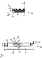
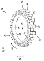
- the spreading roller 1 shown as an example for laterally spreading a flat material web 2 (only indicated schematically by four lines) in axial spreading directions 3 and 4 along the longitudinal extent 5 of the spreading roller 1 has a rotary body 7 that can be rotated about an axis of rotation 6.
- the rotating body 7 is cylindrical in shape and can be made from a wide variety of materials.
- the rotary body 7 is produced by a hollow tube segment (not explicitly numbered), through which an axle part 8 is inserted, with the axis of rotation 6 being formulated by the axle part 8 .
- the rotary body 7 and the axle part 8 are mounted in relation to one another by two ball bearings 9 and 10 so as to be rotatable in relation to one another.
- the axle part 8 is mounted in a rotationally fixed manner on a machine frame (not shown here) for winding flat webs of material.
- the spreading roller 1 in general and the rotating body 7 in particular are set in rotation by the movement of the material web 2 as soon as the spreading roller 1 is brought into operative contact with the running material web 2 when the latter is moved in the transport direction 11 .
- Spreading element rings 15 are mounted on the rotary body 7 in such a way that they spread axially outwards from the central plane 16 of the spreading roller 1 .
- the spreading element rings 15 mounted to the left of the center plane 16 spread to the left in the axial spreading direction 3, while the spreading element rings 15 mounted to the right of the center plane 16 spread to the left in the axial spreading direction 4.
- Each of the spreading element rings 15 comprises a multiplicity of spreading elements 20, by means of which the actual peripheral surface 21 of the spreading roller 1 is also formed.
- This peripheral surface 21 forms the envelope of the spreading roller 1 and thus formulates the outer diameter of the spreading roller 1.
- the spreading elements 20 of a spreading element ring 15 are arranged side by side on the spreading element ring 15 in the circumferential direction 22 of this spreading element ring 15 or the spreading roller 1 .
- a spreading element ring 15 consists essentially of a supporting ring part 24 lying radially further inwards, several contact surface parts 25 lying radially further outwards (numbered only as an example) and several web parts 26 (numbered as examples), by means of which the individual contact surface parts 25 are operatively connected to the supporting ring part 24. If the web parts 26 are approximately V-shaped, special spreading properties can be set advantageously on the respective spreading roller 1 .
- a spreader element 20 is essentially embodied in each case by a contact surface part 25 and a web part 26, with the support ring part 24 being used in the sense of a foot part (not numbered separately) of the spreader element 20 in order to fasten the spreader element 20 to the rotating body 7.
- all spreading elements 20 of a spreading element ring 15 have a common foot part which is configured by the single support ring part 22 of the spreading element ring 15 .
- a peripheral surface gap 27 is provided between the spreading element rings 15 in each case.
- the width of the peripheral surface gap 27 is preferably one to two millimeters, so that sufficient deformation of the expansion elements can be ensured.
- peripheral surface gap 27 in the area of the peripheral surface 21, in particular between two contact surface parts 25 arranged axially one behind the other.
- the main effect of the individual spreading elements 20 is that the material web pressure of the flat material web running over the spreading roller 1 causes a slight deformation of the spreading elements 20 towards the respective end 28 or 29 of the spreading roller 1, which is small, but increases per revolution according to the Repeated number of spreading elements, so that the sum of the deformation leads to a clear but gentle spreading of the flat material web 2 .
- the deformations have the effect that the flat material web 2 is also moved or spread outwards in the axial spreading direction 3 or 4 or in the axial direction of the longitudinal extension 5 of the spreading roller 1, whereby any creases in the material web 2 are eliminated, so that the Material web 2 can be kept smooth overall during transport in transport direction 11 .
- the spreading elements 20 are arranged on the rotary body 7 with different orientations.
- the circumferential surface gap 27 points transversely to the circumferential direction 22 a course 36 (see FIG. 2) with variable axial heights 33.
- This circumferential surface gap 27 prevents an edge end of a flat material web 2 from accidentally buckling into this circumferential surface gap 27, which can be the case with some flat material webs 2 in the prior art.
- the axial heights 33 are determined in relation to the center plane 16 .
- variable axial height curves 36 (sine curve, see figure 2 )
- the peripheral surface gaps 27 formed on the spreading roller 1 are due to the sectional representation of the figure 1 not recognizable, but according to the representation according to the figure 2 , which shows a development 35 of the peripheral surface 21 of the spreading roller 1, wherein the circumferential surface gaps 27, which are curved by way of example, between the adjacent spreading element rings 15 can be seen.
- a small residual gap section 38 remaining in this regard in the circumferential direction 22 is also identified in comparison to a conventional straight gap 37 running perpendicular to the axis of rotation, illustrated only as an example. Due to the remaining gap section 38, only a smaller area acts without a supporting effect, as a result of which the area is so small that there is virtually no longer any negative influence with regard to an unintentional immersion of edge ends of a flat material web 2 .
- a first embodiment of means 40 for avoiding a critical radial immersion of the material web edge 30 or 31 into the peripheral surface gap 27 is realized by the bent or curved peripheral surface gap 27 .
- spreader element rings 42 mounted obliquely on the rotating body 7, whereby an alternative measure for eliminating gaps 37 formed perpendicularly to the axis of rotation 7 (cf. also figure 2 ) can be created.
- the inclined assembly there is in turn a very small remaining gap section 38 at a nip roll cross-sectional plane 43 in which the remaining gap section 38 is arranged centrally.
- the area (not separately numbered) of the residual gap section 38 is so small that its negative influence on the material web edge 30 or 31 no longer occurs.
- the bevel with the angle ⁇ should be dimensioned so that it is slightly larger than the width 44 of the respective expansion element ring 42, so that a remaining gap length in the circumferential direction 22 of a maximum of two expansion element ring widths 44 results.
- the expansion element rings 42 can already be made skewed at the factory to facilitate assembly.
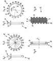
- alternative expansion element rings 50 are used, in which the individual expansion elements 20 are alternately offset from one another in such a way that that the individual spreading elements 20 are shifted axially by half a spreading element width 51 .
- every second spreading element 20 is axially offset in the axial direction by the spreading element width 51 .
- This also reduces a gap length section 52 to the dimension 1/36 of the expansion element ring circumference and is therefore harmless for a critical immersion.
- the dimensions of the inner diameter 53 and outer diameter 54 of the individual expansion element rings 50 are unchanged.
- the support ring part 24 retains its width, and the effective contact surface of the spreader elements 20 also remains the same and therefore equally effective.
- the spreading element ring is also numbered with half the number of spreading elements.
- the reference numeral 56 designates another measure which is 1/18 of the circumference.
- spreading elements 20 are arranged next to one another in the circumferential direction 22 at a distance 58 from one another, which is at least the width of a spreading element 20 in the circumferential direction 22 .
- the distance 58 creates a corresponding gap (not individually numbered here) in the circumferential direction 22 of the expansion element ring 50 .
- axially displaced expansion elements 20 are at least partially covered by the support ring elements 24 .
- the representation according to Figure 5.1 clarifies the present connection again.
- the processing or impression of the contact surface illustrates the distribution of the contact surfaces (contact surface parts 25) of the individual expansion elements 20.
- the respective circumferential surface gap 27 here has abrupt axial offsets, by means of which a number of changes in direction of the circumferential surface gap 27 are associated.
- the spreader elements 20 are offset next to one another on the one hand in the circumferential direction 22 on the spreader element ring 50 and on the other hand additionally in the axial direction 3 or 4 .
- the axial center of the first of the spreading elements 20 is in a first cross-sectional plane of the nip roller 60, and further spreading elements 20 are in a plane-parallel nip roller cross-sectional plane 61 with respect to their axial center.
- two expansion element rings 65 and 66 are rotated by an angle of rotation 67 relative to one another and arranged axially one behind the other in relation to the axis of rotation 6, so that expansion elements 68 of the first expansion element ring 65 engage in gaps 69 between expansion elements 70 of the second expansion element ring 66 and vice versa.
- These spreading elements 68 and 70 are each mounted on a support ring part 74 and 75, which each have only half the width 76 and 77, respectively.
- a centering (not shown) is preferably provided, which ensures that the individual expansion element rings 65 or 66 can always be mounted gap after gap, so that each of the expansion elements 68 or 70 retains its full freedom of movement.
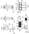
- an assembly aid ring 80 is shown, by means of which expanding element rings 81 (see figure 14 ) or 82 (see figure 15 ) For example, can be mounted on the rotary body 7 of the spreader roller 1.
- the assembly aid ring 80 has a thin-walled, stepped receiving body 83 with two different diameters 84 and 85, so that at least one step 86 is formed on the assembly aid ring 80.
- the stepped receiving body 83 and thus also the auxiliary assembly ring 80 as a whole is characterized by a radially outwardly directed receiving surface 87 for interaction with the expansion element rings 81 or 82 and by a radially inwardly directed contact surface 88 for interaction with the expansion element rings 81 or 82.
- auxiliary assembly ring 80 also has a pressing surface 89, by means of which an expanding element ring 81 or 82 can be pressed against the step 86 when two or more such auxiliary assembly rings 80 are or are mounted one behind the other.
- the pressing surface 89 is arranged at right angles to the receiving surface 87 and the bearing surface 88 .
- This consists of a thin material. This can be a plastic or a thin sheet metal or the like that is shaped into this ring shape.
- the auxiliary assembly ring 80 essentially serves to facilitate the pushing on of expansion element rings 81, 82, etc. It also fixes the expansion element rings 81 or 82 in their position and thus makes further position fixing superfluous.
- the auxiliary assembly ring 80 also has a slot 90 which can be attached almost anywhere on the auxiliary assembly ring 80 .
- the slit 90 enables assembly even with small diameter variations of a spreading roller.
- the slot 90 has the task of prestressing the elastic expansion element rings 81, 82, which arises during assembly, to be transferred to the spreading roller 1 or the like. In this respect, further other fastening options are thereby superfluous.
- each expanding element ring 81 on the auxiliary assembly ring 80 is shown, with each expanding element ring 81 being arranged on the outside of an auxiliary assembly ring 80 .
- auxiliary assembly rings 80 are made of electrically conductive material, they can advantageously also be used to discharge electrostatic charges.
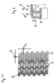
- alternative means 97 for avoiding a critical immersion of a material web edge 30, 31 radially into the circumferential surface gap 96 are also implemented, namely by a gap deflection element 98 (numbered only as an example) and an indentation 99, in which the gap deflection element 98 can engage.
- both the gap deflection element 98 and the indentation 99 can act in the area of a peripheral surface 100 of the spreading roller, both the gap deflection element 98 and the indentation 99 are arranged on a contact surface part 101 of the respective spreading element ring 95 .
- each expansion element 103 of an expansion element ring 95 has an extension lug 104, which protrudes in an approximately U-shaped indentation 105, as a result of which the peripheral surface gap 96 is deflected in the axial direction 106 in the sense of the present invention.
- This will cover a possible gap. It is also important here that the design is carried out in such a way that sufficient freedom of movement is retained for the execution of the spreading movement.
- the expanding element ring 110 shown also has two rows 111 and 112 of expanding elements 113, the rows 111, 112 being arranged axially one behind the other on a common support ring part 114 of the expanding element ring 110 and extending with their expanding elements 113 in the circumferential direction 115 of the expanding element ring 110.
- the spreading elements 113 of the two rows 111 and 112 jump alternately in the axial direction 116 in the course of the circumferential direction 115, so that a meandering circumferential surface gap 117 (shown here only as an example as a section line) results on a spreading roller 1 if several such spreading element rings 110 are arranged axially one behind the other are mounted on the spreader roller 1.
- the expansion element ring 110 includes a positioning and assembly aid 118, which in this exemplary embodiment is characterized by a tongue and groove connection 119 with groove elements 120 and tongue elements 121 on the support ring part 114 . Tongue and groove connections 119 are known per se, so that the principle of action is not further explained here. Suffice it to say that the positioning and assembly aid 118 in the assembled state of a number of expanding element rings 110 arranged axially one behind the other immediately also forms an anti-twist device, which prevents individual expanding element rings 110 from unintentionally rotating on the expanding roller 1 about the axis of rotation 6.
- This alternating arrangement of the individual spreading elements 113 in two rows 111, 112 can also be used to implement differently configured means 122 for avoiding a critical immersion of a material web edge 30, 31 radially into the peripheral surface gap 117.
- the additional expansion element ring 130 shown is also characterized by two rows 131 and 132 of expansion elements 133, with the rows 131 and 132 again having an axial offset 135 in relation to the central axis 134 of the further developed expansion element ring 130 (cf. in particular also figure 20 ) are arranged axially one behind the other on a common support ring part 136 of the further developed spreading element ring 130 .
- the spreading elements 133 of the two rows 131 and 132 arranged axially one behind the other jump here in the course of the circumferential direction 137 (only at figure 21 numbered) alternating in the axial direction 138 (cf. also figure 20 , but only on figure 21 numbered), so that on a spreading roller 1 (see example figure 1 ) results in a meandering circumferential surface gap 140 (shown here again only as an example as a section line), whereby here again a variable axial height profile 36 running transversely to the circumferential direction 137 (see example figure 2 ) can be realized.
- circumferential surface gap 140 shown here is also formulated in this exemplary embodiment by side delimitation sections 140A (numbered only as an example), these flexible side delimitation sections 140A being at least partially configured by the individual spreading elements 133, as is also the case with the above described embodiments is the case, even if it is not explicitly shown or described there.
- a positioning and assembly aid 141 is also provided on the spreading element ring 130 in order to be able to assemble individual spreading element rings 130 in the correct alignment with one another and thus in an operationally reliable manner with respect to a spreading roller 1 .
- the positioning and assembly aid 141 comprises multi-tooth profiles 142 which have a multiplicity of groove elements 143 and tooth elements 144 on both sides of the support ring part 136, namely a first multi-tooth profile 142A and a second multi-tooth profile 142B.
- the tongue and groove elements 143 and 144 are designed in such a way that each tooth element 144 fits positively into each groove element 143, so that with regard to two expanding element rings 130 arranged one behind the other, a very tight twisting grid around the central axis 134 is created. As a result, an anti-twist device is immediately formed, which prevents individual spreading element rings 130 mounted on a spreading roller 1 from unintentionally twisting about the central axis 134 or axis of rotation 6 on this spreading roller 1 .
- This alternating arrangement of the individual spreading elements 133 in two rows 131, 132 also embodies means 145 for avoiding a critical immersion of a material web edge 30, 31 (see figure 1 ) radially into the circumferential surface gap 140.
- Another major advantage of the embodiment variant with the multi-tooth profiles 142 is that individual expansion element rings 130 can be assembled with one another or against one another, with an assembly direction "together” still having a spreading effect on a flat material web 2, while an assembly direction "against each other” has one spread-neutral effect on a flat material web 2 has.
- the spreading elements 133 of the second row 132 are arranged on toothed elements 144 of the multi-tooth profile 142 or the tongue and groove connection, as can also be seen, for example, from the representation according to FIG figure 20 can be seen, in the embodiment according to the figure 20 more than one spreading element 113 is arranged on a spring element 121.
- the spreading elements 133 of the first row 131 are placed axially in front of the individual groove elements 143 .
- the spreading elements 133 are arranged axially in front of the groove elements 143, which are located between the spring elements 144, on which in turn the spreading elements 133 of the second row 132 are arranged.
- the spreading element ring 130 thus has two multiplicity profiles 142 which are designed to be complementary to one another.
- toothed elements 144 of the second multi-toothed profile 142B each have a spreading element 133, in contrast, for example, to that in FIG figure 20 Expanding ring element 110 shown, in which several expanding elements 113 are applied to the spring element 121 there.
- the multi-tooth profiles 142 are provided on the respective edge 146 or 147 of the support ring part 136 .
Landscapes
- Engineering & Computer Science (AREA)
- Mechanical Engineering (AREA)
- Textile Engineering (AREA)
- Absorbent Articles And Supports Therefor (AREA)
- Registering, Tensioning, Guiding Webs, And Rollers Therefor (AREA)
- Rolls And Other Rotary Bodies (AREA)
Claims (15)
- Bague à éléments d'écartement (15, 42, 50, 55, 65, 66, 81, 82, 95, 110, 130) en matériau élastiquement déformable pour un rouleau d'écartement (1) pour l'écartement latéral d'une bande de matériau plane (2) dans des directions d'écartement axiales (3, 4) avec une pluralité d'éléments d'écartement (20, 68, 70, 103, 113, 133), pour laquelle les éléments d'écartement (20, 68, 70, 103, 113, 133) en pluralité sont disposés les uns derrière les autres en direction périphérique (22, 115, 137) de la bague à éléments d'écartement (15, 42, 50, 55, 65, 66, 81, 82, 95, 110, 130) caractérisée en ce que des éléments d'écartement (20, 68, 70, 103, 113, 133) sont disposés transversalement à la direction périphérique (22, 115, 137) et de ce fait axialement décalés les uns par rapport aux autres sur la bague à éléments d'écartement (15, 42, 50, 55, 65, 66, 81, 82, 95, 110, 130).
- Bague à éléments d'écartement (15, 42, 50, 55, 65, 66, 81, 82, 95, 110, 130) selon la revendication 1, caractérisée en ce que les éléments d'écartement (20, 68, 70, 103, 113, 133) sont disposés les uns à côté des autres espacés les uns des autres en direction périphérique (22, 115, 137) à une distance (58) qui représente au moins la largeur d'un élément d'écartement (20, 68, 70, 103, 113, 133) en direction périphérique (22, 115, 137), sachant que cette distance (58) conditionne un vide dans lequel est disposé seulement en partie un élément d'écartement (20, 68, 70, 103, 113, 133), sont disposés de préférence deux éléments d'écartement (20, 68, 70, 103, 113, 133).
- Bague à éléments d'écartement (15, 42, 50, 55, 65, 66, 81, 82, 95, 110, 130) selon la revendication 1 ou 2, caractérisée en ce qu'un élément d'écartement (20, 68, 70, 103, 113, 133) axialement déporté à cet effet est disposé (A8) entre deux éléments d'écartement (20, 68, 70, 103, 113, 133) espacés l'un de l'autre d'une distance (58) en direction périphérique (22, 115, 137).
- Bague à éléments d'écartement (15, 42, 50, 55, 65, 66, 81, 82, 95, 110, 130) selon l'une quelconque des revendications 1 à 3, caractérisée en ce que les éléments d'écartement (20, 68, 70, 103, 113, 133) individuels de la bague à éléments d'écartement (15, 42, 50, 55, 65, 66, 81, 82, 95, 110, 130) sont disposés l'un par rapport à l'autre de telle manière que les éléments d'écartement (20, 68, 70, 103, 113, 133) individuels constituent un espace de surface périphérique (27, 71, 96, 117, 140) passant en direction périphérique (22, 115, 137)..
- Bague à éléments d'écartement (15, 42, 50, 55, 65, 66, 81, 82, 95, 110, 130) selon la revendication 4, caractérisée en ce que l'espace de surface périphérique (27, 71, 96, 117, 140) est généré par le fait que les éléments d'écartement (20, 68, 70, 103, 113, 133) individuels sont axialement désenclenchés à partir d'une pluralité d'éléments d'écartement (20, 68, 70, 103, 113, 133) disposés les uns près des autres dans la direction périphérique (22, 115, 137).
- Bague à éléments d'écartement (15, 42, 50, 55, 65, 66, 81, 82, 95, 110, 130) selon la revendication 4 ou 5, caractérisée en ce que l'espace de surface périphérique (27, 71, 96, 117, 140) est constitué modifiable axialement de façon flexible en direction axiale (138).
- Bague à éléments d'écartement (15, 42, 50, 55, 65, 66, 81, 82, 95, 110, 130) selon l'une quelconque des revendications 4 à 6, caractérisée en ce que l'espace de surface périphérique (27, 71, 96, 117, 140) comporte des sections de délimitation latérales flexibles (140A), sachant que ces sections de délimitation latérales flexibles (140A) sont constituées par des éléments d'écartement (20, 68, 70, 103, 113, 133) individuels.
- Bague à éléments d'écartement (15, 42, 50, 55, 65, 66, 81, 82, 95, 110, 130) selon l'une quelconque des revendications 4 à 7, caractérisée en ce que l'espace de surface périphérique (27, 71, 96, 117, 140) présente transversalement à la direction périphérique (22, 115, 137) au moins une courbe, en particulier une courbe sinusoïdale.
- Bague à éléments d'écartement (15, 42, 50, 55, 65, 66, 81, 82, 95, 110, 130) selon l'une quelconque des revendications 4 à 8, caractérisée en ce que l'espace de surface périphérique (27, 71, 96, 117, 140) est constitué en forme de méandres dans la direction périphérique (22, 115, 137).
- Bague à éléments d'écartement (15, 42, 50, 55, 65, 66, 81, 82, 95, 110, 130) selon l'une quelconque des revendications 1 à 9, caractérisée en ce que les bagues à éléments d'écartement (15, 42, 50, 55, 65, 66, 81, 82, 95, 110, 130) directement voisines sont reliées de façon fonctionnelle au moyen d'un assemblage à rainure et languette (119).
- Bague à éléments d'écartement (15, 42, 50, 55, 65, 66, 81, 82, 95, 110, 130) selon la revendication 10, caractérisée en ce que des éléments d'écartement (20, 68, 70, 103, 113, 133) sont disposés sur un élément faisant ressort (121) de l'assemblage à rainure et languette (119).
- Bague à éléments d'écartement (15, 42, 50, 55, 65, 66, 81, 82, 95, 110, 130) selon la revendication 10 ou 11, caractérisée en ce qu'un élément à rainure (120) est disposé axialement opposé à un élément faisant ressort (121) comportant un élément d'écartement (20, 68, 70, 103, 113, 133).
- Bague à éléments d'écartement (15, 42, 50, 55, 65, 66, 81, 82, 95, 110, 130) selon l'une quelconque des revendications 1 à 12, caractérisée en ce que la bague à éléments d'écartement (15, 42, 50, 55, 65, 66, 81, 82, 95, 110, 130) comprend au moins un profil à denture multiple (142, 142A, 142B), lequel est disposé sur un bord (146, 147) d'une partie annulaire de support (24, 74, 75, 114, 136) de la bague à éléments d'écartement (15, 42, 50, 55, 65, 66, 81, 82, 95, 110, 130).
- Bague à éléments d'écartement (15, 42, 50, 55, 65, 66, 81, 82, 95, 110, 130) selon l'une quelconque des revendications 1 à 13, caractérisée en ce qu'un élément d'écartement (20, 68, 70, 103, 113, 133) de la bague à éléments d'écartement (15, 42, 50, 55, 65, 66, 81, 82, 95, 110, 130) est disposé sur un élément denté (144) d'un profil à denture multiple (142, 142A, 142B) constitué sur la bague à éléments d'écartement (15, 42, 50, 55, 65, 66, 81, 82, 95, 110, 130).
- Rouleau d'écartement (1) pour l'écartement latéral d'une bande de matériau plane (2) dans des directions d'écartement axiales (3, 4) avec une pluralité de bagues à éléments d'écartement (15, 42, 50, 55, 65, 66, 81, 82, 95, 110, 130) comprenant des éléments d'écartement (20, 68, 70, 103, 113, 133) individuels, lesquels forment une surface périphérique (21, 100) pour laquelle un espace de surface périphérique (27, 71, 96, 117, 140) est formé entre les éléments d'écartement (20, 68, 70, 103, 113, 133) individuels sur la surface périphérique (21, 100), lequel s'étend en direction périphérique (22, 115, 137) autour du rouleau d'écartement (1), caractérisé par des bagues à éléments d'écartement (15, 42, 50, 55, 65, 66, 81, 82, 95, 110, 130) selon l'une quelconque des revendications précédentes.
Applications Claiming Priority (3)
| Application Number | Priority Date | Filing Date | Title |
|---|---|---|---|
| DE102017007807 | 2017-08-17 | ||
| DE102017008468.8A DE102017008468B4 (de) | 2017-08-17 | 2017-09-08 | SPREIZWALZE UND SPRElZELEMENTERING FÜR EINE DERARTIGE SPREIZWALZE SOWIE MONTAGEHILFSRING UND VERFAHREN |
| PCT/DE2018/000236 WO2019034191A1 (fr) | 2017-08-17 | 2018-08-14 | Rouleau d'écartement et bague à éléments d'écartement pour un tel rouleau d'écartement ainsi que bague d'aide au montage et procédé de fabrication associé |
Publications (2)
| Publication Number | Publication Date |
|---|---|
| EP3668809A1 EP3668809A1 (fr) | 2020-06-24 |
| EP3668809B1 true EP3668809B1 (fr) | 2023-02-22 |
Family
ID=65234867
Family Applications (1)
| Application Number | Title | Priority Date | Filing Date |
|---|---|---|---|
| EP18772710.2A Active EP3668809B1 (fr) | 2017-08-17 | 2018-08-14 | Bague à éléments d'écartement pour un rouleau d'écartement et rouleau d'écartement |
Country Status (5)
| Country | Link |
|---|---|
| EP (1) | EP3668809B1 (fr) |
| DE (2) | DE102017008468B4 (fr) |
| DK (1) | DK3668809T3 (fr) |
| ES (1) | ES2944695T3 (fr) |
| WO (1) | WO2019034191A1 (fr) |
Families Citing this family (3)
| Publication number | Priority date | Publication date | Assignee | Title |
|---|---|---|---|---|
| DE102020002112A1 (de) | 2020-04-01 | 2021-10-07 | Rolf Hessenbruch | Spreizelementring oder Spreizelementleiste, Spreizwalze sowie Verfahren zum Herstellen eines solchen Spreizelementrings oder Spreizelementleiste aus recycelfähigem thermoplastischem Elastomer |
| IT202000016018A1 (it) * | 2020-07-02 | 2022-01-02 | Barnini S R L | Rullo stenditore |
| JP2024132126A (ja) * | 2023-03-17 | 2024-09-30 | セイコーエプソン株式会社 | 凹凸ローラー、媒体搬送装置、記録装置、後処理装置、中継装置、凹凸リング、凹凸ローラーの製造方法 |
Family Cites Families (9)
| Publication number | Priority date | Publication date | Assignee | Title |
|---|---|---|---|---|
| DE300550C (fr) | ||||
| GB190907944A (en) | 1908-04-02 | 1909-11-11 | Wilhelm Mueller | Spreading and Guiding Roller for Fabrics and the like. |
| US1716555A (en) | 1926-06-08 | 1929-06-11 | Thomas E Kane | Method of spreading or stretching material |
| CH593192A5 (fr) | 1975-10-01 | 1977-11-30 | Benninger Ag Maschf | |
| CH599022A5 (fr) * | 1976-09-10 | 1978-05-12 | Fred H Freuler | |
| GB2071625B (en) * | 1980-03-11 | 1983-09-21 | Eberlin Edgar Anthony | Device for spreading or tensioning a moving sheet or web |
| US6382797B1 (en) * | 2000-10-17 | 2002-05-07 | 20/10 Perfect Vision Optische Geraete Gmbh | Aberration-free delivery system |
| DE102011107188B4 (de) | 2011-01-28 | 2019-09-12 | Rolf Hessenbruch | Spreizwalze zum seitlichen Ausbreiten von Flachbahnen |
| DE102016005546A1 (de) | 2016-05-09 | 2017-11-09 | Rolf Hessenbruch | Spreizwalze zum seitlichen ausbreiten einer flächigen materialbahn, verfahren zum spreizen einer flächigen materialbahn sowie vorrichtung zum handhaben von flächigen materialbahnen |
-
2017
- 2017-09-08 DE DE102017008468.8A patent/DE102017008468B4/de active Active
-
2018
- 2018-08-14 ES ES18772710T patent/ES2944695T3/es active Active
- 2018-08-14 DK DK18772710.2T patent/DK3668809T3/da active
- 2018-08-14 EP EP18772710.2A patent/EP3668809B1/fr active Active
- 2018-08-14 DE DE112018004175.1T patent/DE112018004175A5/de not_active Withdrawn
- 2018-08-14 WO PCT/DE2018/000236 patent/WO2019034191A1/fr not_active Ceased
Also Published As
| Publication number | Publication date |
|---|---|
| ES2944695T3 (es) | 2023-06-23 |
| EP3668809A1 (fr) | 2020-06-24 |
| DE112018004175A5 (de) | 2020-04-30 |
| DE102017008468A1 (de) | 2019-02-21 |
| DK3668809T3 (da) | 2023-05-30 |
| DE102017008468B4 (de) | 2019-07-04 |
| WO2019034191A1 (fr) | 2019-02-21 |
Similar Documents
| Publication | Publication Date | Title |
|---|---|---|
| EP3216347B1 (fr) | Procédé pour orienter des produits à base de pâte enroulée dans une position finale définie | |
| EP3668809B1 (fr) | Bague à éléments d'écartement pour un rouleau d'écartement et rouleau d'écartement | |
| DE1761077A1 (de) | Vorrichtung zum Pressen von in einem kontinuierlichen Strom anfallenden,biegsamen Flaechengebilden | |
| EP3455151A1 (fr) | Élément d'élargissement, anneau d'éléments d'élargissement, dispositif pour élargir une bande de matériau plate, rouleau élargisseur pour étaler latéralement une bande de matériau plate, procédé d'élargissement d'une bande de matériau plate ainsi que dispositif de manipulation de bandes de matériau plates | |
| EP3129668A1 (fr) | Ensemble palier segmenté avec cage en matière plastique fixée par complémentarité de formes | |
| DE4015245C2 (de) | Durchbiegungseinstellwalze | |
| DE4211264C2 (de) | Uhrfederverbinder | |
| EP2960194B1 (fr) | Molette de pliage avec pièces rapportées en caoutchouc élastique | |
| DE102004053125B4 (de) | Wälzlageranordnung | |
| EP3911590A1 (fr) | Dispositif d'écartement ainsi que procédé pour l'écartement d'une bande de matériau plane, rouleau élargisseur et utilisation d'un élément d'écartement individuel dans un tel rouleau élargisseur | |
| EP0703176A1 (fr) | Rouleau élargisseur | |
| EP2687361A1 (fr) | Machine destinée à la fabrication de carton ondulé | |
| EP0770571A2 (fr) | Dispositif pour le guidage transitoire de feuilles se succédant | |
| EP4298044B1 (fr) | Rouleau déplisseur et dispositif de lissage d'un matériau textile au moyen d'un rouleau déplisseur | |
| DE19818234A1 (de) | Rollprofiliereinrichtung zur Herstellung von Roll- oder Walzprofilelementen | |
| EP3359478B1 (fr) | Courroie de pliage pour dispositif de pliage de découpes à plat de boîte pliante | |
| DE60130310T2 (de) | Breitstreckwalze für Gewebe oder dergleichen | |
| EP0462434A1 (fr) | Rouleau pour machines à papier | |
| DE29522327U1 (de) | Breitstreckwalze | |
| DE4042365C2 (de) | Durchbiegungseinstellwalze | |
| DE1964717A1 (de) | Axialrollenlager | |
| DE10024894C1 (de) | Mehrreihiges Wälzlager | |
| DE3143201C2 (de) | Transportwelle in einer Durchlauf-Entwicklungsmaschine für fotografische Bänder | |
| EP3515629B1 (fr) | Procédé et dispositif pour élargir un élément métallique | |
| EP3168337B1 (fr) | Dispositif destine au transport guide d'une bande de voile |
Legal Events
| Date | Code | Title | Description |
|---|---|---|---|
| STAA | Information on the status of an ep patent application or granted ep patent |
Free format text: STATUS: UNKNOWN |
|
| STAA | Information on the status of an ep patent application or granted ep patent |
Free format text: STATUS: THE INTERNATIONAL PUBLICATION HAS BEEN MADE |
|
| PUAI | Public reference made under article 153(3) epc to a published international application that has entered the european phase |
Free format text: ORIGINAL CODE: 0009012 |
|
| STAA | Information on the status of an ep patent application or granted ep patent |
Free format text: STATUS: REQUEST FOR EXAMINATION WAS MADE |
|
| 17P | Request for examination filed |
Effective date: 20200311 |
|
| AK | Designated contracting states |
Kind code of ref document: A1 Designated state(s): AL AT BE BG CH CY CZ DE DK EE ES FI FR GB GR HR HU IE IS IT LI LT LU LV MC MK MT NL NO PL PT RO RS SE SI SK SM TR |
|
| AX | Request for extension of the european patent |
Extension state: BA ME |
|
| DAV | Request for validation of the european patent (deleted) | ||
| DAX | Request for extension of the european patent (deleted) | ||
| GRAP | Despatch of communication of intention to grant a patent |
Free format text: ORIGINAL CODE: EPIDOSNIGR1 |
|
| STAA | Information on the status of an ep patent application or granted ep patent |
Free format text: STATUS: GRANT OF PATENT IS INTENDED |
|
| RIC1 | Information provided on ipc code assigned before grant |
Ipc: D06C 3/06 20060101ALI20220824BHEP Ipc: B29C 53/18 20060101ALI20220824BHEP Ipc: B65H 27/00 20060101ALI20220824BHEP Ipc: B65H 23/34 20060101ALI20220824BHEP Ipc: B65H 23/025 20060101AFI20220824BHEP |
|
| INTG | Intention to grant announced |
Effective date: 20220927 |
|
| GRAS | Grant fee paid |
Free format text: ORIGINAL CODE: EPIDOSNIGR3 |
|
| GRAA | (expected) grant |
Free format text: ORIGINAL CODE: 0009210 |
|
| STAA | Information on the status of an ep patent application or granted ep patent |
Free format text: STATUS: THE PATENT HAS BEEN GRANTED |
|
| AK | Designated contracting states |
Kind code of ref document: B1 Designated state(s): AL AT BE BG CH CY CZ DE DK EE ES FI FR GB GR HR HU IE IS IT LI LT LU LV MC MK MT NL NO PL PT RO RS SE SI SK SM TR |
|
| REG | Reference to a national code |
Ref country code: GB Ref legal event code: FG4D Free format text: NOT ENGLISH |
|
| REG | Reference to a national code |
Ref country code: CH Ref legal event code: EP |
|
| REG | Reference to a national code |
Ref country code: DE Ref legal event code: R096 Ref document number: 502018011651 Country of ref document: DE |
|
| REG | Reference to a national code |
Ref country code: AT Ref legal event code: REF Ref document number: 1549393 Country of ref document: AT Kind code of ref document: T Effective date: 20230315 Ref country code: IE Ref legal event code: FG4D Free format text: LANGUAGE OF EP DOCUMENT: GERMAN |
|
| REG | Reference to a national code |
Ref country code: DK Ref legal event code: T3 Effective date: 20230524 |
|
| REG | Reference to a national code |
Ref country code: LT Ref legal event code: MG9D |
|
| P01 | Opt-out of the competence of the unified patent court (upc) registered |
Effective date: 20230505 |
|
| REG | Reference to a national code |
Ref country code: ES Ref legal event code: FG2A Ref document number: 2944695 Country of ref document: ES Kind code of ref document: T3 Effective date: 20230623 |
|
| REG | Reference to a national code |
Ref country code: NL Ref legal event code: FP |
|
| PG25 | Lapsed in a contracting state [announced via postgrant information from national office to epo] |
Ref country code: RS Free format text: LAPSE BECAUSE OF FAILURE TO SUBMIT A TRANSLATION OF THE DESCRIPTION OR TO PAY THE FEE WITHIN THE PRESCRIBED TIME-LIMIT Effective date: 20230222 Ref country code: PT Free format text: LAPSE BECAUSE OF FAILURE TO SUBMIT A TRANSLATION OF THE DESCRIPTION OR TO PAY THE FEE WITHIN THE PRESCRIBED TIME-LIMIT Effective date: 20230622 Ref country code: NO Free format text: LAPSE BECAUSE OF FAILURE TO SUBMIT A TRANSLATION OF THE DESCRIPTION OR TO PAY THE FEE WITHIN THE PRESCRIBED TIME-LIMIT Effective date: 20230522 Ref country code: LV Free format text: LAPSE BECAUSE OF FAILURE TO SUBMIT A TRANSLATION OF THE DESCRIPTION OR TO PAY THE FEE WITHIN THE PRESCRIBED TIME-LIMIT Effective date: 20230222 Ref country code: LT Free format text: LAPSE BECAUSE OF FAILURE TO SUBMIT A TRANSLATION OF THE DESCRIPTION OR TO PAY THE FEE WITHIN THE PRESCRIBED TIME-LIMIT Effective date: 20230222 Ref country code: HR Free format text: LAPSE BECAUSE OF FAILURE TO SUBMIT A TRANSLATION OF THE DESCRIPTION OR TO PAY THE FEE WITHIN THE PRESCRIBED TIME-LIMIT Effective date: 20230222 |
|
| PG25 | Lapsed in a contracting state [announced via postgrant information from national office to epo] |
Ref country code: SE Free format text: LAPSE BECAUSE OF FAILURE TO SUBMIT A TRANSLATION OF THE DESCRIPTION OR TO PAY THE FEE WITHIN THE PRESCRIBED TIME-LIMIT Effective date: 20230222 Ref country code: PL Free format text: LAPSE BECAUSE OF FAILURE TO SUBMIT A TRANSLATION OF THE DESCRIPTION OR TO PAY THE FEE WITHIN THE PRESCRIBED TIME-LIMIT Effective date: 20230222 Ref country code: IS Free format text: LAPSE BECAUSE OF FAILURE TO SUBMIT A TRANSLATION OF THE DESCRIPTION OR TO PAY THE FEE WITHIN THE PRESCRIBED TIME-LIMIT Effective date: 20230622 Ref country code: GR Free format text: LAPSE BECAUSE OF FAILURE TO SUBMIT A TRANSLATION OF THE DESCRIPTION OR TO PAY THE FEE WITHIN THE PRESCRIBED TIME-LIMIT Effective date: 20230523 Ref country code: FI Free format text: LAPSE BECAUSE OF FAILURE TO SUBMIT A TRANSLATION OF THE DESCRIPTION OR TO PAY THE FEE WITHIN THE PRESCRIBED TIME-LIMIT Effective date: 20230222 |
|
| PG25 | Lapsed in a contracting state [announced via postgrant information from national office to epo] |
Ref country code: SM Free format text: LAPSE BECAUSE OF FAILURE TO SUBMIT A TRANSLATION OF THE DESCRIPTION OR TO PAY THE FEE WITHIN THE PRESCRIBED TIME-LIMIT Effective date: 20230222 Ref country code: RO Free format text: LAPSE BECAUSE OF FAILURE TO SUBMIT A TRANSLATION OF THE DESCRIPTION OR TO PAY THE FEE WITHIN THE PRESCRIBED TIME-LIMIT Effective date: 20230222 Ref country code: EE Free format text: LAPSE BECAUSE OF FAILURE TO SUBMIT A TRANSLATION OF THE DESCRIPTION OR TO PAY THE FEE WITHIN THE PRESCRIBED TIME-LIMIT Effective date: 20230222 Ref country code: CZ Free format text: LAPSE BECAUSE OF FAILURE TO SUBMIT A TRANSLATION OF THE DESCRIPTION OR TO PAY THE FEE WITHIN THE PRESCRIBED TIME-LIMIT Effective date: 20230222 |
|
| REG | Reference to a national code |
Ref country code: DE Ref legal event code: R097 Ref document number: 502018011651 Country of ref document: DE |
|
| PG25 | Lapsed in a contracting state [announced via postgrant information from national office to epo] |
Ref country code: SK Free format text: LAPSE BECAUSE OF FAILURE TO SUBMIT A TRANSLATION OF THE DESCRIPTION OR TO PAY THE FEE WITHIN THE PRESCRIBED TIME-LIMIT Effective date: 20230222 |
|
| PLBE | No opposition filed within time limit |
Free format text: ORIGINAL CODE: 0009261 |
|
| STAA | Information on the status of an ep patent application or granted ep patent |
Free format text: STATUS: NO OPPOSITION FILED WITHIN TIME LIMIT |
|
| 26N | No opposition filed |
Effective date: 20231123 |
|
| PG25 | Lapsed in a contracting state [announced via postgrant information from national office to epo] |
Ref country code: SI Free format text: LAPSE BECAUSE OF FAILURE TO SUBMIT A TRANSLATION OF THE DESCRIPTION OR TO PAY THE FEE WITHIN THE PRESCRIBED TIME-LIMIT Effective date: 20230222 |
|
| PG25 | Lapsed in a contracting state [announced via postgrant information from national office to epo] |
Ref country code: MC Free format text: LAPSE BECAUSE OF FAILURE TO SUBMIT A TRANSLATION OF THE DESCRIPTION OR TO PAY THE FEE WITHIN THE PRESCRIBED TIME-LIMIT Effective date: 20230222 |
|
| PG25 | Lapsed in a contracting state [announced via postgrant information from national office to epo] |
Ref country code: MC Free format text: LAPSE BECAUSE OF FAILURE TO SUBMIT A TRANSLATION OF THE DESCRIPTION OR TO PAY THE FEE WITHIN THE PRESCRIBED TIME-LIMIT Effective date: 20230222 |
|
| PG25 | Lapsed in a contracting state [announced via postgrant information from national office to epo] |
Ref country code: LU Free format text: LAPSE BECAUSE OF NON-PAYMENT OF DUE FEES Effective date: 20230814 |
|
| PG25 | Lapsed in a contracting state [announced via postgrant information from national office to epo] |
Ref country code: LU Free format text: LAPSE BECAUSE OF NON-PAYMENT OF DUE FEES Effective date: 20230814 |
|
| REG | Reference to a national code |
Ref country code: IE Ref legal event code: MM4A |
|
| PG25 | Lapsed in a contracting state [announced via postgrant information from national office to epo] |
Ref country code: IE Free format text: LAPSE BECAUSE OF NON-PAYMENT OF DUE FEES Effective date: 20230814 |
|
| PG25 | Lapsed in a contracting state [announced via postgrant information from national office to epo] |
Ref country code: IE Free format text: LAPSE BECAUSE OF NON-PAYMENT OF DUE FEES Effective date: 20230814 |
|
| PGFP | Annual fee paid to national office [announced via postgrant information from national office to epo] |
Ref country code: NL Payment date: 20240821 Year of fee payment: 7 |
|
| PGFP | Annual fee paid to national office [announced via postgrant information from national office to epo] |
Ref country code: DK Payment date: 20240829 Year of fee payment: 7 |
|
| PGFP | Annual fee paid to national office [announced via postgrant information from national office to epo] |
Ref country code: BE Payment date: 20240821 Year of fee payment: 7 |
|
| PGFP | Annual fee paid to national office [announced via postgrant information from national office to epo] |
Ref country code: FR Payment date: 20240830 Year of fee payment: 7 |
|
| PGFP | Annual fee paid to national office [announced via postgrant information from national office to epo] |
Ref country code: AT Payment date: 20240822 Year of fee payment: 7 |
|
| PGFP | Annual fee paid to national office [announced via postgrant information from national office to epo] |
Ref country code: IT Payment date: 20240827 Year of fee payment: 7 |
|
| PG25 | Lapsed in a contracting state [announced via postgrant information from national office to epo] |
Ref country code: BG Free format text: LAPSE BECAUSE OF FAILURE TO SUBMIT A TRANSLATION OF THE DESCRIPTION OR TO PAY THE FEE WITHIN THE PRESCRIBED TIME-LIMIT Effective date: 20230222 |
|
| PG25 | Lapsed in a contracting state [announced via postgrant information from national office to epo] |
Ref country code: BG Free format text: LAPSE BECAUSE OF FAILURE TO SUBMIT A TRANSLATION OF THE DESCRIPTION OR TO PAY THE FEE WITHIN THE PRESCRIBED TIME-LIMIT Effective date: 20230222 |
|
| PG25 | Lapsed in a contracting state [announced via postgrant information from national office to epo] |
Ref country code: CY Free format text: LAPSE BECAUSE OF FAILURE TO SUBMIT A TRANSLATION OF THE DESCRIPTION OR TO PAY THE FEE WITHIN THE PRESCRIBED TIME-LIMIT; INVALID AB INITIO Effective date: 20180814 |
|
| PG25 | Lapsed in a contracting state [announced via postgrant information from national office to epo] |
Ref country code: HU Free format text: LAPSE BECAUSE OF FAILURE TO SUBMIT A TRANSLATION OF THE DESCRIPTION OR TO PAY THE FEE WITHIN THE PRESCRIBED TIME-LIMIT; INVALID AB INITIO Effective date: 20180814 |
|
| PGFP | Annual fee paid to national office [announced via postgrant information from national office to epo] |
Ref country code: ES Payment date: 20250926 Year of fee payment: 8 |
|
| PGFP | Annual fee paid to national office [announced via postgrant information from national office to epo] |
Ref country code: DE Payment date: 20250831 Year of fee payment: 8 |
|
| PGFP | Annual fee paid to national office [announced via postgrant information from national office to epo] |
Ref country code: GB Payment date: 20250820 Year of fee payment: 8 |
|
| PGFP | Annual fee paid to national office [announced via postgrant information from national office to epo] |
Ref country code: CH Payment date: 20250901 Year of fee payment: 8 |
|
| PG25 | Lapsed in a contracting state [announced via postgrant information from national office to epo] |
Ref country code: TR Free format text: LAPSE BECAUSE OF FAILURE TO SUBMIT A TRANSLATION OF THE DESCRIPTION OR TO PAY THE FEE WITHIN THE PRESCRIBED TIME-LIMIT Effective date: 20230222 |
|
| REG | Reference to a national code |
Ref country code: DK Ref legal event code: EBP Effective date: 20250831 |
|
| REG | Reference to a national code |
Ref country code: NL Ref legal event code: MM Effective date: 20250901 |
|
| PG25 | Lapsed in a contracting state [announced via postgrant information from national office to epo] |
Ref country code: AT Free format text: LAPSE BECAUSE OF NON-PAYMENT OF DUE FEES Effective date: 20250814 |
|
| REG | Reference to a national code |
Ref country code: AT Ref legal event code: MM01 Ref document number: 1549393 Country of ref document: AT Kind code of ref document: T Effective date: 20250814 |