EP3668966B1 - Arrangement d'electrodes adaptatif pour la mise en oueuvre dans un système incubateur de cellules et ses utilisations - Google Patents
Arrangement d'electrodes adaptatif pour la mise en oueuvre dans un système incubateur de cellules et ses utilisations Download PDFInfo
- Publication number
- EP3668966B1 EP3668966B1 EP18759217.5A EP18759217A EP3668966B1 EP 3668966 B1 EP3668966 B1 EP 3668966B1 EP 18759217 A EP18759217 A EP 18759217A EP 3668966 B1 EP3668966 B1 EP 3668966B1
- Authority
- EP
- European Patent Office
- Prior art keywords
- well
- electrode
- electrodes
- pair
- adaptive
- Prior art date
- Legal status (The legal status is an assumption and is not a legal conclusion. Google has not performed a legal analysis and makes no representation as to the accuracy of the status listed.)
- Active
Links
Images





Classifications
-
- G—PHYSICS
- G01—MEASURING; TESTING
- G01N—INVESTIGATING OR ANALYSING MATERIALS BY DETERMINING THEIR CHEMICAL OR PHYSICAL PROPERTIES
- G01N33/00—Investigating or analysing materials by specific methods not covered by groups G01N1/00 - G01N31/00
- G01N33/48—Biological material, e.g. blood, urine; Haemocytometers
- G01N33/50—Chemical analysis of biological material, e.g. blood, urine; Testing involving biospecific ligand binding methods; Immunological testing
- G01N33/5005—Chemical analysis of biological material, e.g. blood, urine; Testing involving biospecific ligand binding methods; Immunological testing involving human or animal cells
-
- C—CHEMISTRY; METALLURGY
- C12—BIOCHEMISTRY; BEER; SPIRITS; WINE; VINEGAR; MICROBIOLOGY; ENZYMOLOGY; MUTATION OR GENETIC ENGINEERING
- C12M—APPARATUS FOR ENZYMOLOGY OR MICROBIOLOGY; APPARATUS FOR CULTURING MICROORGANISMS FOR PRODUCING BIOMASS, FOR GROWING CELLS OR FOR OBTAINING FERMENTATION OR METABOLIC PRODUCTS, i.e. BIOREACTORS OR FERMENTERS
- C12M1/00—Apparatus for enzymology or microbiology
- C12M1/42—Apparatus for the treatment of microorganisms or enzymes with electrical or wave energy, e.g. magnetism, sonic waves
-
- C—CHEMISTRY; METALLURGY
- C12—BIOCHEMISTRY; BEER; SPIRITS; WINE; VINEGAR; MICROBIOLOGY; ENZYMOLOGY; MUTATION OR GENETIC ENGINEERING
- C12M—APPARATUS FOR ENZYMOLOGY OR MICROBIOLOGY; APPARATUS FOR CULTURING MICROORGANISMS FOR PRODUCING BIOMASS, FOR GROWING CELLS OR FOR OBTAINING FERMENTATION OR METABOLIC PRODUCTS, i.e. BIOREACTORS OR FERMENTERS
- C12M23/00—Constructional details, e.g. recesses, hinges
- C12M23/02—Form or structure of the vessel
- C12M23/12—Well or multiwell plates
-
- C—CHEMISTRY; METALLURGY
- C12—BIOCHEMISTRY; BEER; SPIRITS; WINE; VINEGAR; MICROBIOLOGY; ENZYMOLOGY; MUTATION OR GENETIC ENGINEERING
- C12M—APPARATUS FOR ENZYMOLOGY OR MICROBIOLOGY; APPARATUS FOR CULTURING MICROORGANISMS FOR PRODUCING BIOMASS, FOR GROWING CELLS OR FOR OBTAINING FERMENTATION OR METABOLIC PRODUCTS, i.e. BIOREACTORS OR FERMENTERS
- C12M35/00—Means for application of stress for stimulating the growth of microorganisms or the generation of fermentation or metabolic products; Means for electroporation or cell fusion
- C12M35/02—Electrical or electromagnetic means, e.g. for electroporation or for cell fusion
-
- C—CHEMISTRY; METALLURGY
- C12—BIOCHEMISTRY; BEER; SPIRITS; WINE; VINEGAR; MICROBIOLOGY; ENZYMOLOGY; MUTATION OR GENETIC ENGINEERING
- C12N—MICROORGANISMS OR ENZYMES; COMPOSITIONS THEREOF; PROPAGATING, PRESERVING, OR MAINTAINING MICROORGANISMS; MUTATION OR GENETIC ENGINEERING; CULTURE MEDIA
- C12N13/00—Treatment of microorganisms or enzymes with electrical or wave energy, e.g. magnetism, sonic waves
-
- C—CHEMISTRY; METALLURGY
- C12—BIOCHEMISTRY; BEER; SPIRITS; WINE; VINEGAR; MICROBIOLOGY; ENZYMOLOGY; MUTATION OR GENETIC ENGINEERING
- C12N—MICROORGANISMS OR ENZYMES; COMPOSITIONS THEREOF; PROPAGATING, PRESERVING, OR MAINTAINING MICROORGANISMS; MUTATION OR GENETIC ENGINEERING; CULTURE MEDIA
- C12N5/00—Undifferentiated human, animal or plant cells, e.g. cell lines; Tissues; Cultivation or maintenance thereof; Culture media therefor
- C12N5/06—Animal cells or tissues; Human cells or tissues
- C12N5/0602—Vertebrate cells
- C12N5/0652—Cells of skeletal and connective tissues; Mesenchyme
- C12N5/0657—Cardiomyocytes; Heart cells
-
- G—PHYSICS
- G01—MEASURING; TESTING
- G01N—INVESTIGATING OR ANALYSING MATERIALS BY DETERMINING THEIR CHEMICAL OR PHYSICAL PROPERTIES
- G01N33/00—Investigating or analysing materials by specific methods not covered by groups G01N1/00 - G01N31/00
- G01N33/48—Biological material, e.g. blood, urine; Haemocytometers
- G01N33/50—Chemical analysis of biological material, e.g. blood, urine; Testing involving biospecific ligand binding methods; Immunological testing
- G01N33/5005—Chemical analysis of biological material, e.g. blood, urine; Testing involving biospecific ligand binding methods; Immunological testing involving human or animal cells
- G01N33/5008—Chemical analysis of biological material, e.g. blood, urine; Testing involving biospecific ligand binding methods; Immunological testing involving human or animal cells for testing or evaluating the effect of chemical or biological compounds, e.g. drugs, cosmetics
-
- G—PHYSICS
- G01—MEASURING; TESTING
- G01N—INVESTIGATING OR ANALYSING MATERIALS BY DETERMINING THEIR CHEMICAL OR PHYSICAL PROPERTIES
- G01N33/00—Investigating or analysing materials by specific methods not covered by groups G01N1/00 - G01N31/00
- G01N33/48—Biological material, e.g. blood, urine; Haemocytometers
- G01N33/50—Chemical analysis of biological material, e.g. blood, urine; Testing involving biospecific ligand binding methods; Immunological testing
- G01N33/5005—Chemical analysis of biological material, e.g. blood, urine; Testing involving biospecific ligand binding methods; Immunological testing involving human or animal cells
- G01N33/5008—Chemical analysis of biological material, e.g. blood, urine; Testing involving biospecific ligand binding methods; Immunological testing involving human or animal cells for testing or evaluating the effect of chemical or biological compounds, e.g. drugs, cosmetics
- G01N33/5044—Chemical analysis of biological material, e.g. blood, urine; Testing involving biospecific ligand binding methods; Immunological testing involving human or animal cells for testing or evaluating the effect of chemical or biological compounds, e.g. drugs, cosmetics involving specific cell types
- G01N33/5061—Muscle cells
-
- C—CHEMISTRY; METALLURGY
- C12—BIOCHEMISTRY; BEER; SPIRITS; WINE; VINEGAR; MICROBIOLOGY; ENZYMOLOGY; MUTATION OR GENETIC ENGINEERING
- C12N—MICROORGANISMS OR ENZYMES; COMPOSITIONS THEREOF; PROPAGATING, PRESERVING, OR MAINTAINING MICROORGANISMS; MUTATION OR GENETIC ENGINEERING; CULTURE MEDIA
- C12N2506/00—Differentiation of animal cells from one lineage to another; Differentiation of pluripotent cells
- C12N2506/45—Differentiation of animal cells from one lineage to another; Differentiation of pluripotent cells from artificially induced pluripotent stem cells
-
- C—CHEMISTRY; METALLURGY
- C12—BIOCHEMISTRY; BEER; SPIRITS; WINE; VINEGAR; MICROBIOLOGY; ENZYMOLOGY; MUTATION OR GENETIC ENGINEERING
- C12N—MICROORGANISMS OR ENZYMES; COMPOSITIONS THEREOF; PROPAGATING, PRESERVING, OR MAINTAINING MICROORGANISMS; MUTATION OR GENETIC ENGINEERING; CULTURE MEDIA
- C12N2529/00—Culture process characterised by the use of electromagnetic stimulation
Definitions
- the present disclosure generally relates to electrode arrangements for wells and well-plates and, more particularly, an adaptive electrode arrangement and method for introducing an electric field to a sample well or a plurality of wells of a microwell plate.
- Various cells such as cardiomyocytes, are often used in an in vitro setting in the study of cardiac disease models.
- the sources of these cells can originate from primary isolated heart muscles or differentiated from induced pluripotent stem cells (iPSCs).
- the isolated primary cells depending on maturation stage (i.e ., embryonic versus adult), may not be able to contract autonomously as in the whole heart due to the absence of pacer cell signaling or the functions of certain ion channels.
- external electrical pacing is required to properly elicit the contractile properties of these cells to resemble their physiological behavior in vivo.
- the contractile function of the cells which is a key metric in assessing new therapies, can be measured using various assay methods such as calcium flux or direct force measurement.
- External electrical pacing has also been cited to affect the maturation of iPSC derived cardiomyocytes in culture. Namely, early onset of stimulation can modify beating rhythm and contraction propagation profiles of the cardiomyocytes. In addition, external pacing of the cells helps the synchronization in measurement, which results in better signal window and data interpretation.
- the application of electric field stimulation or pacing of cells is not only limited to cardiomyocytes, but is also in the study of voltage-gated ion channels or membrane potential.
- rigid, multi-array field stimulation electrode designs have been produced before for this purpose.
- such conventional electrode designs typically require precisely measuring the depth of a well to understand how deep the electrodes must be lowered into the well to affect a uniform electric field across the cells in the well, for example.
- the uniform electric field is the field between overlapping parallel electrodes. The problem becomes even more obvious if the subjected cells are at or near the bottom of the well in which case it requires lowering the electrodes to reach the bottom of the well to affect the uniform electric field.
- Disclosed herein are devices and methods that provide for providing an electrical stimulus across a population of cells in a well, regardless of the substrate geometry of the well.
- a well for electrically stimulating at least one cell has a bottom portion.
- the well comprises an adaptive electrode arrangement for introducing an electric field into the well, and the adaptive electrode arrangement includes a pair of electrodes disposed within the well, the pair of electrodes having a distal end and independently and axially displaceable relative to each other and the bottom portion of the well. The distal end of each electrode of the pair of electrodes is in contact with the bottom portion of the well, ensuring a uniform and constant electric field is applied within the well.
- a microwell plate assembly comprises a microwell plate having a plurality of wells, and each well of the plurality of wells has a bottom portion.
- the microwell plate assembly also includes an array of adaptive electrode arrangements for introducing an electric field into each well of the plurality of wells.
- Each adaptive electrode arrangement includes a pair of electrodes disposed within the well of the plurality of wells, and each electrode of the pair of electrodes has a distal end and is independently and axially displaceable relative to each other and the bottom portion of the well; The distal end of each electrode of the pair of electrodes is in contact with the bottom portion of the well, ensuring a uniform and constant electric field is applied within the well.
- an adaptive electrode arrangement for a microwell plate comprises one of a circuit board or a cover plate and a pair of electrodes coupled to one of the circuit board or the cover plate and adapted to be disposed within a well of a plurality of wells.
- the pair of electrodes is independently and axially displaceable relative to a bottom portion of the well and each other, and each electrode of the pair of electrodes has a distal end.
- the distal end of each electrode of the pair of electrodes is adapted to be in constant contact with the bottom portion of the well when disposed within the well, ensuring a uniform and constant electric field is applied within the well.
- a method of introducing an electric field into a well comprises disposing a pair of electrodes within the well and independently and axially displacing each electrode of the pair of electrodes relative to each other to enable a distal end of each electrode of the pair of electrodes to contact a bottom portion of the well.
- the method further comprises maintaining constant contact of the distal end of each electrode of the pair of electrodes with the bottom portion of the well and applying a uniform electric field within the well.
- a method of synchronizing a behavior of a population of cells by introducing an electric field into a well of a plurality of wells of a microwell plate comprises adding the population of cells in a well of the plurality of wells.
- the method also includes disposing a pair of electrodes within the well of the plurality of wells, and independently and axially displacing each electrode of the pair of electrodes relative to each other to enable a distal end of each electrode of the pair of electrodes to contact a bottom portion of the well.
- the method further includes maintaining constant contact of the distal end of each electrode of the pair of electrodes with the bottom portion of the well, and applying a uniform electric field within the well, such that the behavior of each cell of the population of cells is approximately synchronized.
- a method of altering a membrane potential of a cell by introducing an electric field into a well of a microwell plate assembly comprises adding a cell in a well of the microwell plate assembly and disposing a pair of electrodes within the well.
- the method also includes independently and axially displacing each electrode of the pair of electrodes relative to each other to enable a distal end of each electrode of the pair of electrodes to contact a bottom portion of the well.
- the method further includes maintaining constant contact of the distal end of each electrode of the pair of electrodes with the bottom portion of the well, and applying a uniform electric field within the well, such that the membrane potential of the cell is excited.
- a cell incubator system comprises a container and a microwell plate assembly disposed within the container.
- the microwell plate assembly may include a microwell plate having a plurality of wells and an array of electrode arrangements for introducing an electric field into each well of the plurality of wells.
- Each electrode arrangement may have a pair of electrodes and one of a cover plate or a circuit board to which the pair of electrodes is coupled.
- Each of the cover plate and the circuit board may have an opening for enabling solution to be dispensed into the well while the electric field is being applied within the well.
- a microwell plate assembly adapted to be one or more of disposed in a container of a cell incubator system or coupled to cell culture support utilities may comprise a microwell plate having a plurality of wells and an array of electrode arrangements for introducing an electric field into each well of the plurality of wells.
- Each electrode arrangement may have a pair of electrodes and one of a cover plate or a circuit board to which the pair of electrodes is coupled.
- Each of the cover plate and the circuit board may have an opening for enabling solution to be dispensed into the well while the electric field is being applied within the well.
- one or more of the well, the microwell plate assembly, the adaptive electrode arrangement, and related methods may include any one or more of the following forms or method steps.
- the well may further comprise one or more of at least one micropost, a microwire formed around the at least one micropost, a bottom surface, a base disposed on the bottom surface, and a ramp, one of extending or separate from the base, to which the at least one micropost is attached.
- the bottom portion may include one or more of the bottom surface, the base, and the ramp, such that the distal end of each electrode of the pair of electrodes is in contact with one of the bottom surface, the base, or the ramp of the well.
- the well may further comprise at least one micropost having a length, and each electrode of the pair of electrodes may include a length that is at least about the same or greater than the length of at least one micropost.
- a circuit board to which the adaptive electrode arrangement is integrated may be coupled to the well.
- the circuit board may include a plurality of openings and a through-hole disposed on either side of each opening, the through-hole for receiving a proximal end of each electrode of the pair of electrodes.
- a spring for securing each proximal end of each electrode of the pair of electrodes to the circuit board and enabling each electrode to be independently and axially displaceable may also be included.
- each electrode of the pair of electrodes may be disposed on either side of an opening of the plurality of openings of the circuit board.
- the adaptive electrode arrangement may further include a cover plate having a pair of through-holes, each through-hole for receiving a proximal end of each electrode of the pair of electrodes.
- Each electrode may be axially displaceable along an axis of the cover plate, which allows each electrode to move relative to one or more of the bottom portion of the well and the cover plate.
- the adaptive electrode arrangement may further include a cover plate having a distal portion, and each electrode of the pair of electrodes having a proximal end.
- a spring with a first end attached to the distal portion of the cover plate and a second end coupled to the proximal end of each electrode of the pair of electrodes may also be included to couple each electrode to the cover plate, allowing each electrode to be axially displaceable along an axis of the cover plate. Still further, the distal end of each electrode of the pair of electrodes may be in constant contact with the bottom portion of the well, and the bottom portion of the well may include one or more of a bottom surface, a base, or a ramp of the well. In addition, each cover plate above the well may include an opening disposed between the pair of electrodes to allow for dispensing of solution within the well while the electric field is being applied within the well.
- a first spring having a first portion and a second portion is included.
- the first portion may be coupled to a proximal end of a first electrode disposed on a first side of the circuit board, and the second portion may be coupled to a proximal end of a second electrode disposed on the first side of the circuit board.
- the spring may be for securing the first and second electrodes to the circuit board and enabling axial displacement of the first and second electrodes.
- a second spring having a first portion and a second portion may also be included.
- the first portion may be coupled to a proximal end of a third electrode disposed on a second side of the circuit board opposite the first electrode, and the second portion may be coupled to a proximal end of a fourth electrode disposed on the second side of the circuit board opposite the second electrode.
- the spring may be for securing the third and fourth electrodes to the circuit board and enabling axial displacement of the third and fourth electrodes. So configured, the first and third electrodes may be disposed on either side of a first opening of the plurality of openings of the circuit board, and the second and fourth electrodes may be disposed on either side of a second opening of the plurality of openings of the circuit board.
- the first and third electrodes may form a pair of electrodes of a first adaptive electrode arrangement of the array of adaptive electrode arrangements, and the second and fourth electrodes may form a pair of electrodes of a second adaptive electrode arrangement of the array of adaptive electrode arrangements.
- the method may comprise providing a length of each electrode of the pair of electrodes that is at least about equal to or greater than a length of a micropost disposed in the well.
- independently and axially displacing each electrode of the pair of electrodes relative to each other may comprise providing one of at least one through-hole disposed within one of a lid or a cover plate for receiving a proximal end of each electrode of the pair of electrodes, or at least one spring for coupling the proximal end of each electrode to one of a lid or a cover plate.
- maintaining constant contact of a distal end of each electrode of the pair of electrodes with the bottom portion of the well may comprise providing at least one through-hole within a cover plate for receiving a proximal end of each electrode or at least one spring having a first end attached to the cover plate and a second end attached to the proximal end of each electrode of the pair of electrodes, allowing the distal end of each electrode to move relative to the cover plate and each other to accommodate different heights and/or geometric configurations of the bottom portion of the well.
- the method may further comprise integrating a pair of electrodes into a circuit board of a microwell plate assembly by one or more of at least one spring or at least one through-hole disposed within the circuit board before disposing the pair of electrodes within the well.
- the method may also include providing an array of adaptive electrode arrangements, each adaptive electrode arrangement having a pair of electrodes and the well is one well of a plurality of wells of a microwell plate assembly, and controlling stimulation inputs by wiring the pairs of electrodes in parallel or in series to one or multiple pulse generators and amplifiers through the circuit board.
- the method may also comprise dispensing solution through at least one opening disposed in one or more of a circuit board of a microwell plate assembly or a cover plate coupled to the pair of electrodes while simultaneously applying the electric field within the well of the plurality of wells.
- maintaining constant contact of the distal end of each electrode of the pair of electrodes within the bottom portion of the well may include preventing cells adapted to be disposed within the well from being stimulated by a fringe of an electric field.
- maintaining constant contact of the distal end of each electrode of the pair of electrodes within the bottom portion of the well may comprise maintaining constant contact of the distal end of each electrode with the bottom portion regardless of a depth of different areas of the bottom portion of the well.
- independently and axially displacing each electrode of the pair of electrodes relative to each other to enable a distal end of each electrode of the pair of electrodes to contact a bottom portion of the well may comprise displacing a distal end of a first electrode of the pair of electrodes to be in contact with the bottom portion of the well at one of a lower depth than, a same depth as, or a higher depth than a distal end of the second electrode of the pair of electrodes in contact with the bottom portion of the well.
- devices that enable the application of an electric field to, for example, a population of cells, in a well, wherein the electric field is uniform and/or extended despite the geometry of the substrate of the well.
- the disclosed devices and associated methods dispense of the necessity of measuring the well depth to precisely position the electrodes that provide the electric field.
- the disclosed apparatuses and methods virtually eliminate the possibility of cells not receiving the electric signal because the applied electric field reaches cells that have, for example, fallen into a bottom area or fringes of the wells.
- disclosed embodiments permit not only the ability to culture easily cells that have been electrically stimulated, but for permit reagent dispensing, even while simultaneously conducting the electrical stimulation of the cells. As such, electrical stimulation that can induce certain cell types to differentiate and mature can be applied to cells, and the cells cultured in conventional cell incubators.
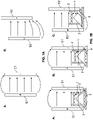
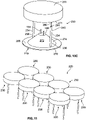
- FIGS. 1A-1D show some of the challenges of delivering an electric field using electrodes in a vessel, such as a well of a microwell plate.
- FIG. 1A shows the electrical field that is generated between electrodes.
- the electrodes E1 are fixed into position. When an electric field is generated between them, the field is substantially uniform between the bodies of the electrodes E1 (as represented by parallel arrows). However, at the proximal and distal ends of the electrodes E1, an electric field is still present, but is not substantially uniform (represented by the curved arrows).
- FIG. 1A (B) a pair of adaptive (offsetting) electrodes E2 is shown.
- the generated electric field remains substantially uniform (parallel arrows) where the two electrodes E2 are parallel o, or overlap, each other; however, where they are off-set, such as at the bottom of the electrodes, a field still passes between the electrodes E2, but is not substantially uniform.
- FIG. 1B shows how these electrode positions deliver electric stimulation to cells on cardiac microwires.
- Cardiac microwires are cultured cardiomyocytes that make a bridge of cells ("wire") 1 between two posts 2 that are placed in the well. The cells form these wires by migrating from the floor of the well, up the posts 2, and then form the wire 1.
- the cardiac microwire device is shown in FIG. 1B as two vertical horizontal posts 2 between the electrodes E1 (labeled "+” and "-”).
- the oval shapes represent cardiac myocytes.
- the cells forming the wire near the top of the microwire device), receive a substantially uniform electric field (parallel arrows).
- Cells at the bottom of the well 3 are also electrically stimulated, but receive a non-uniform electric field (curved arrow).
- the electrodes E1 are off-center ( FIG. 1B(B) )
- the electrodes E1 are physically obstructed from properly immersing into the well, and the cells at the bottom of the well 3 receive an even weaker signal because they are farther away from the electrodes E1; furthermore, the electric field is also non-uniform (curved arrow).
- adaptive electrodes E2 can be used ( FIG. 1B(C) ).
- Electrodes E2 from this electrode configuration accommodate the physical obstruction and reach as far to the bottom as possible, independently, thus extending the electric field and keeping a majority of the cells in the uniform portion of the electric field (parallel arrows) and yet still able to cover the bottommost cells 3 on its fringe, albeit the delivered electric field is not uniform (curved arrows).
- FIG. 1D demonstrates the advantages of adaptive electrodes E2 as more specifically disclosed herein. Regardless of the well bottom 5 height of the various wells 6, 7, 8, adaptive electrodes E2 always touch the bottom 5 of each of the wells 6, 7, 8, delivering a uniform electric field (parallel arrows) to the cells 4 in the wells 6, 7, 8, as depicted in FIG. 1D(A-C) . In such a configuration, the cells 4 are no longer stimulated by the field fringes of conventional fixed-height electrodes E1.
- an adaptive electrode arrangement for a well such as a well of a microwell plate assembly
- the adaptive electrode arrangement includes one of a circuit board or a cover plate and a pair of electrodes coupled to one of the circuit board or the cover plate.
- the pair of electrodes is adapted to be disposed within the well of the microwell plate assembly and is independently and axially displaceable relative to a bottom portion of the well and each other.
- Each electrode of the pair of electrodes has a distal end that is in constant contact with the bottom portion of the well when disposed within the well. In this way, a uniform and extended electric field is applied within the well regardless of the various geometries of the well, such as a bottom portion of the well.
- each electrode of the pair of electrodes may move relative to one of the circuit board or the cover plate to accommodate different heights and/or geometric configurations of the bottom portion of the well, ensuring the distal end of each electrode maintains constant contact with the bottom portion of the well.
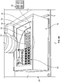
- the microwell plate assembly 10 includes a body 12, such as a container, or may be disposed within the container, and a lid 14 that fits over the body 12.
- the microwell plate assembly 10 further includes a microwell plate 16 disposed within the body 12 and having a plurality of wells 18.
- An array of adaptive electrode arrangements 20 for introducing an electric field into each well 19 of the plurality of wells 18 is also included, as explained more below.
- the well 19 is for electrically stimulating at least one cell, as also explained more below.
- the container may be disposed within a cell incubator system 21, as depicted in FIG.
- the microwell plate assembly 10 may be equipped with, such as coupled to, additional internal or external cell culture support utilities 23, which may include one or more of a carbon dioxide (CO 2 ) element 25, an oxygen (O2) element 27, a humidified gas element 29, and one or more temperature control elements 31.
- additional internal or external cell culture support utilities 23 may include one or more of a carbon dioxide (CO 2 ) element 25, an oxygen (O2) element 27, a humidified gas element 29, and one or more temperature control elements 31.
- the microwell plate assembly 10 may be disconnected from electrical equipment when needed, for example.
- FIG. 3 the microwell plate 16 having the plurality of wells with multiple arrays 20 of adaptive electrode arrangements coupled thereto is depicted outside of the body 12 illustrated in FIGS. 1 and 2 .
- FIG. 3 there may be twelve arrays 20 of adaptive electrode arrangements coupled to the microwell plate 16.
- FIGS. 2A and 2B depict six arrays 20 of adaptive electrode arrangements coupled to the microwell plate 16.
- any number of arrays of adaptive electrode arrangements may alternatively be disposed on and/or within the microwell plate 16 to introduce the electric field within each corresponding well 19 and still fall within the scope of the present disclosure.
- 1, 2, 3, 4, 5, 6, 7, 8, 9, 10, 11, and 12 or more arrays of adaptive electrode arrangements may be coupled to the microwell plate.
- the microwell plate assembly 10 may include a circuit board 22 that is coupled to the microwell plate 16 and to which the array 20 of adaptive electrode arrangements is integrated.
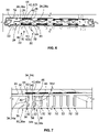
- the circuit board 22 may include a plurality of openings 24 and a through-hole 26 disposed on either side of each opening 28 of the plurality of openings 24, as partially depicted in FIG. 3 .
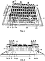
- the circuit board 22 may include multiple sections, wherein each section includes multiple arrays of adaptive electrode arrangements, and each array of adaptive electrode arrangements includes multiple adaptive electrode arrangements. More specifically, and in one example, the circuit board 22 may include three sections 22a, 22b and 22c, as depicted in FIG. 4 . In this example, each of the three sections 22a, 22b and 22c of the circuit board 22 may include four arrays 20 of adaptive electrode arrangements 30, as illustrated relative to section 22a in FIG 4 . Each array 20 of adaptive electrode arrangements may include eight adaptive electrode arrangements.
- each section may alternatively include more or fewer arrays 20 of adaptive electrode arrangements and each array may alternatively include more or fewer than eight adaptive electrode arrangements and still fall within the scope of the present disclosure.
- the circuit board 22 of FIGS. 2A and 2B includes three sections, each of which includes two arrays 20 of adaptive electrode arrangements.
- the circuit board 22 may alternatively include a single unibody (not shown) having multiple arrays of adaptive electrode arrangements, each array having more than one adaptive electrode arrangement, for example, and still fall within the scope of the present disclosure.
- each adaptive electrode arrangement 30 introduces an electric field into the well 19 and includes a pair of electrodes 32 ( FIG. 7 ) disposed within the well 19 of the plurality of wells 18.
- Each electrode 34 of the pair of electrodes 32 has a distal end 36 and is independently and axially displaceable relative to each other and a bottom portion 38 of the well 19. As a result, the distal end 36 of each electrode 34 is in constant contact with the bottom portion 38 of the well 19, ensuring a uniform and constant electric field is applied within the well 19.
- each electrode 34 of the pair of electrodes 32 also includes a proximal end 40.
- the through-hole 26 ( FIG. 6 ) disposed on either side of the opening 28 of the circuit board 22 receives the proximal end 40 of each electrode 34 to couple the pair of electrodes 32 to the circuit board 22.
- the microwell plate assembly 10 may further include at least one spring 42 having a first portion 44 and a second portion 46.
- the first portion 44 is coupled to the proximal end 40 of the electrode 34, such as a first electrode 34a ( FIG. 7 ), disposed on a first side 50 of the circuit board 22.
- the second portion 46 is coupled to the proximal end 40 of another electrode, such as a second electrode 34b ( FIG. 7 ), also disposed on the first side 50 of the circuit board 22.
- At least one spring 42 which may be a first spring 42a, secures the first and second electrodes 34a, 34b to the circuit board 22 and enables axial displacement of the first and second electrodes 34a, 34b relative to the bottom portion 38 ( FIG. 5 ) of the well 19, for example.
- the microwell plate assembly 10 may further include a second spring 42b having a first portion 44 and a second portion 46.
- the first portion 44 of the second spring 42b is coupled to the proximal end 40 of a third electrode 34c ( FIG. 7 ) disposed on a second side 52 ( FIG. 6 ) of the circuit board 22 opposite the first electrode 34a.
- the second portion 46 of the second spring 42b is coupled to a proximal end 40 of a fourth electrode 34d ( FIG. 7 ) disposed on the second side 52 of the circuit board 22 opposite the second electrode 34b.
- the second spring 42b secures the third and fourth electrodes 34c, 34d to the circuit board 22 and enables axial displacement of the third and fourth electrodes 34c, 34d.
- the first and third electrodes 34a, 34c, respectively are disposed on either side of a first opening 28a ( FIG. 6 ) of the plurality of openings and the second and fourth electrodes 34b, 34d, respectively, are disposed on either side of a second opening 28b ( FIG. 6 ).
- the first and third electrodes 34a, 34c, respectively form a pair of electrodes of a first adaptive electrode arrangement 30a.
- the second and fourth electrodes 34b, 34d respectively, form a pair of electrodes of a second adaptive electrode arrangement 30b.
- an adaptive electrode arrangement 130 may be used in the microwell plate assembly 10 of FIGS. 1-3 .
- one or more of the adaptive electrode arrangements 130 may alternatively form the arrays 20 of adaptive electrode arrangements of the microwell plate assembly 10.
- the adaptive electrode arrangement 130 is similar to the adaptive electrode arrangement 30 of FIG. 5 , but also includes a cover plate, as described more below.
- Parts of the adaptive electrode arrangement 130 similar or identical to parts of the adaptive electrode arrangement 30 are numbered 100 more than the parts of the adaptive electrode arrangement 30.
- parts of the adaptive electrode arrangement 130 different from the adaptive electrode arrangement 30 of Figs. 5-7 include different reference numbers and are explained more below.
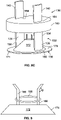
- the adaptive electrode arrangement 130 is for introducing an electric field into the well 19 ( FIG. 1 ) or a well 119, which is partially depicted in FIGS. 8A-8C .
- the adaptive electrode arrangement 130 includes a pair of electrodes 132 disposed within the well 19, 119.
- Each electrode 134 of the pair of electrodes 132 has a distal end 136 and a proximal end 140 and is independently and axially displaceable relative to each other and the bottom portion 138 of the well 19, 119.
- the distal end 136 of each electrode 134 is in contact, such as constant contact, with the bottom portion 138 of the well 19, 119, ensuring one or more of a uniform and constant or extended electric field is applied within the well 19, 119.
- the adaptive electrode arrangement 130 also includes a cover plate 160 having a pair of through-holes 162.
- Each through-hole 164 receives the proximal end 140 of each electrode 134 of the pair of electrodes 132. So configured, each electrode 134 is axially displaceable along an axis of the cover plate 160, allowing each electrode 134 to move or be moveable relative to one or more of the bottom portion 138 of the well 119 and the cover plate 160.
- the well 119 partially depicted in FIGS. 8A-8C may include at least one micropost 166 having a length L1.
- the well 119 includes two microposts 166, each of which includes a length L1.
- each electrode 134 includes a length L2 that is either the same as or greater than (as depicted in FIG. 8A ) the length L1 of the microposts 166.
- a microwire 168 is formed around the at least one micropost 166.
- the well 119 may also include a bottom surface 170, a base 172 disposed on the bottom surface 170, and a ramp 174 to which the at least one micropost 166 may be attached.
- the ramp 174 may upwardly extend from the base 172 or be separate from the base 172.
- the bottom portion 138 may include one or more of the bottom surface 170, the base 172, and the ramp 174, such that the distal end 136 of each electrode 134 of the pair of electrodes 132 is in contact with one or more of the bottom surface 170, the base 172 or the ramp 174 of the well 119.
- the bottom portion 138 of the well 119 may be one or more of flat, convex or concave or any other geometric configuration.
- Each electrode 134 of the pair of electrodes 132 may move axially and independently of each other to maintain constant contact with the bottom portion 138 of the well 119, regardless of the geometric configuration of the well 119.
- the well 19 may also include each of the same features as the well 119 of FIGS. 8A-8C , for example, such as the microposts 166, the microwire 168, a bottom surface 170, a base 172 disposed on the bottom surface, and a ramp 174 to which the at least one micropost 166 may be attached.
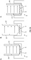
- FIGS. 8A and 8C depict both distal ends 136 of each electrode 134 in contact with the ramp 174 of the well 119.
- FIG. 8B depicts one distal end 136 of one electrode 134 in contact with the ramp 174, while the other distal end 136 of the other electrode 134 is in contact with the bottom surface 170 of the well.
- the configuration of the electrodes 134 in FIG. 8B depicts an example in which the electrodes 134 are inadvertently placed in a position offset from the ramp 174 of FIGS. 8A and 8C , for example. Because the electrodes 134 are axially moveable relative to each other and the cover plate 160, for example, the electrodes 134 automatically adapt to the different geometric surfaces of FIG.
- FIG. 8C further depicts an exemplary shape of the electrodes 134. More specifically, in one example, the electrodes 134 may be a partially cylindrical, curved, plate-like shape, as depicted in FIG. 8C .
- the electrodes 134 may alternatively take the form of various other shapes, such as one or more of octagonal, hexagonal, rectangular, cylindrical, circular, semi-cylindrical, semi-circular, and/or triangular in shape and still fall within the scope of the present disclosure.
- the well 119 includes two microposts 166 and a microwire 168 formed around the microposts 166.
- the microposts 166 include outwardly extending end portions at a proximal end of each micropost 166.
- the microposts 166 may alternatively be various other shapes and configurations and still fall within the scope of the present disclosure.
- the microposts 166 may alternatively be one or more of octagonal, hexagonal, rectangular, cylindrical, circular, semi-cylindrical, semi-circular and/or triangular in shape and still fall within the scope of the present disclosure.
- the microposts 166 are disposed on and attached to the base 172 of the well 119, which includes a ramp 174.
- an adaptive electrode arrangement 230 may alternatively be used in the arrays 20 of adaptive electrode arrangements of the microwell plate assembly 10 of FIGS. 1-3 instead of the adaptive electrode arrangements 30, 130 for example.
- the adaptive electrode arrangement 230 is similar to the adaptive electrode arrangement 30 of FIG. 5 , but also includes a cover plate and springs, as described more below.
- Parts of the adaptive electrode arrangement 230 of FIGS. 10A-10C that are similar or identical to parts of the adaptive electrode arrangement 30 are numbered 200 more than the parts of the adaptive electrode arrangement 30.
- parts of the adaptive electrode arrangement 230 that are different from the adaptive electrode arrangement 30 of Figs. 5-7 include different reference numbers and are explained more below.
- the adaptive electrode arrangement 230 is for introducing an electric field into the well 19 of FIG. 1 , for example, or a well 219, which is partially depicted in FIGS. 10A-10B .
- the adaptive electrode arrangement 230 includes a pair of electrodes 232 adapted to be disposed within the well 219.
- Each electrode 234 of the pair of electrodes 232 has a distal end 236 and a proximal end 240 and is independently and axially displaceable relative to each other and the bottom portion 238 of the well 219.
- the distal end 236 of each electrode 234 is in contact, such as constant contact, with the bottom portion 238 of the well 219, ensuring one or more of a uniform and constant or extended electric field is applied within the well.
- the adaptive electrode arrangement 230 also includes a cover plate 260 and a distal portion 271.
- a spring 280 having a first end 282 and a second end 284 attaches each electrode 234 to the cover plate 260. More specifically, the first end 282 of the spring 280 is attached to the distal portion 271 of the cover plate 260. The second end 284 of the spring 280 is attached to the proximal end 240 of one electrode 234 of the pair of electrodes 232.
- another spring 280 has a first end 282 also attached to the distal portion 270 of the cover plate 260 and a second end 284 attached to the proximal end 240 of the other electrode 234 of the pair of electrodes 232. So configured, each electrode 234 is allowed to be axially displaceable relative to the cover plate 260, such as axially displaceable along an axis of the cover plate 260.
- the well 219 is partially depicted in FIGS. 10A-10C , for example. Similar to wells 19, 119, the well 219 includes at least one micropost 266 having a length L1. In one example, the well 219 includes two microposts 266, each of which include a length L1. In addition, each electrode 234 includes a length L2 that is either the same as or greater than (as depicted in FIGS. 10A-10B ) the length L1 of the microposts 266. Further, the well 219 may also include a bottom surface 270, a base 272 disposed on the bottom surface 270, and a ramp 274 to which the at least one micropost 266 may be attached.
- the ramp 274 may upwardly extend from the base 272 or be separate from the base 272.
- the bottom portion 238 may include one or more of the bottom surface 270, the base 272, and the ramp 274, such that the distal end 236 of each electrode 234 of the pair of electrodes 232 is in contact with one or more of the bottom surface 270, the base 272 or the ramp 274 of the well 219.
- the bottom portion 238 of the well 219 may be one or more of flat, convex or concave or any other geometric configuration.
- Each electrode 234 of the pair of electrodes 232 may move axially and independently of each other to maintain constant contact with the bottom portion 238 of the well 219, regardless of the geometric configuration of the well 219.
- FIG. 10A depicts the distal end 236 of one electrode 234 of the pair of electrodes 232 in contact with the ramp 274 of the well 219.
- the distal end 236 of the other electrode 234 of the pair of electrodes is also in contact with the ramp 274.
- the pair of electrodes 232 of the adaptive electrode arrangement 230 are offset, such that the distal end 236 of the one electrode 234 is now in contact with the bottom surface 270 of the bottom portion 238 of the well 219.
- the distal end 236 of the other electrode 234 of the pair of electrodes 232 is still in contact with the ramp 274, but contacts the ramp 274 at a position closer to the micropost 266, for example.
- the electrodes 234 are axially moveable relative to each other and the cover plate 260, for example, via the springs 280, the electrodes 234 automatically adapt to the different geometric surfaces of the well 219 and move downwardly toward the bottom portion 238. As a result, one electrode 234 is able to maintain contact with the ramp 274, and the other electrode 234 moves in a downward direction to contact the bottom surface 270. So configured, cells disposed between the electrodes 234, and not outside of the electrodes 234, such as on a fringe area 286 ( FIGS. 10A , 10C ) of the well 119, are stimulated by one or more of the uniform or the extended electric field.
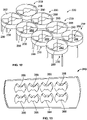
- the array 220 includes eight adaptive electrode arrangements 230, each of which includes a pair of electrodes 232 attached to the cover plate 260, as explained relative to FIGS. 10A-10C , for example. While not depicted, the array 220 of the adaptive electrode arrangements 230 may be integrated into the microwell plate assembly 10 of FIGS. 1-3 , for example, such as into the circuit board 22.
- each cover plate 260 of each adaptive electrode arrangement 230 includes an opening 288.
- the opening 288 is disposed between the pair of electrodes 232 to allow for dispensing of solution within the well 19, 219, at any time, including while the electric field is being applied to the well 19, 219, for example. While the opening 288 is depicted as circular in part and semi-circular in part, the opening 288 may alternatively be various other shapes and sizes and still fall within the scope of the present disclosure.
- openings 288 are depicted in the array 220 of the adaptive electrode arrangement 230, the opening 288 may be included in a single adaptive electrode arrangement 230, such as any of the adaptive electrode arrangements depicted in FIGS. 10A-10C or FIGS. 8A-8C .
- openings 388 may be formed in a microwell electrode holder 310 to which an array of adaptive electrode arrangements may be coupled.
- the openings 388 again allow for electrode insertion and solution dispensing at any time, including while an electric field is being applied to the well by the electrodes.
- the openings 388 may be any shape or combination of shapes and still fall within the scope of the present disclosure.
- the method comprises disposing the pair of electrodes 32, 132, 232 within the well 19, 119, 219 of the microwell plate assembly 10, for example.
- the method further comprises independently and axially displacing each electrode 34, 134, 234 of the pair of electrodes 32, 132, 232 relative to each other to enable a distal end 36, 136, 236 of each electrode 34, 134, 234 to contact a bottom portion 38, 138, 238 of the well 19, 119, 219.
- the method also comprises maintaining constant contact of the distal end 36, 136, 236 of each electrode 34, 134, 234 of the pair of electrodes 32, 132, 232 with the bottom portion 38, 138, 238 and applying one or more of a uniform or extended electric field within the well 19, 119, 219.
- the method 400 may further comprise providing a length of each electrode 34, 134, 234 of the pair of electrodes 32, 132, 232 that is at least about equal to or greater than a length of a micropost 166, 266 disposed in the well 19, 119, 219.
- each electrode 34, 134, 234 of the pair of electrodes 32, 132, 232 may comprise providing one of at least one through-hole 28, 164 disposed within one of the circuit board 22 or the cover plate 160 for receiving a proximal end 40, 140 of each electrode 34, 134, 234 of the pair of electrodes 32, 132, 232, or at least one spring 42, 280 for coupling the proximal end 40, 240 of each electrode 34, 234 to one of the circuit board 22 or the cover plate 260.
- maintaining constant contact of a distal end 36, 136, 236 of each electrode 34, 134, 234 of the pair of electrodes 32, 132, 232 with the bottom portion 38, 138, 238 of the well 19, 119, 219 may comprise providing at least one through-hole 164 within a cover plate 160 for receiving a proximal end 140 of each electrode 134 or at least one spring 280 having a first end 282 attached to the cover plate 260 and a second end 284 attached to the proximal end 240 of each electrode 234 of the pair of electrodes 232.
- each electrode 134, 234 moves relative to the cover plate 160, 260 and each other to accommodate different heights and/or geometric configurations of the bottom portion 38, 138, 238 of the well 19, 119, 219.
- the method 400 may further comprise integrating a pair of electrodes 32, 132, 232 into the circuit board 22 of a microwell plate assembly 10 by one or more of at least one spring 42 or at least one through-hole 26 disposed within the circuit board 22.
- the pair of electrodes 32, 132, 232 may be disposed within the well 19 before or after being disposed within the circuit board.
- the method 400 may further comprise providing an array 20 of adaptive electrode arrangements 30, 130, 230, each adaptive electrode arrangement 30, 130, 230 having a pair of electrodes 32, 132, 232, and controlling stimulation inputs by wiring the pairs of electrodes 32, 132, 232 in parallel or in series to multiple pulse generators and amplifiers through the circuit board 22.
- the method 400 may also further comprise dispensing solution through at least one opening 28, 288, 388 disposed in one or more of a circuit board 22 of a microwell plate assembly 10 or a cover plate 160, 260 coupled to the pair of electrodes 32, 132, 232, while simultaneously applying the electric field within the well 19, 119, 219 of the plurality of wells.
- maintaining constant contact of the distal end 36, 136, 236 of each electrode 34, 134, 234 of the pair of electrodes 32, 132, 232 within the bottom portion 38, 138, 238 of the well 19, 119, 219 may include preventing cells adapted to be disposed within the well 19, 119, 219 from being stimulated by a fringe of the electric field. More specifically, and as described above relative to FIG. 1B (B) , conventional fixed height electrodes do not always contact the bottom portion of the well, resulting in cells at the bottom of the well being disposed below the fixed height electrodes and, thus, stimulated by a fringe of the electric field of the electrodes, which is a non-uniform electric field, for example.
- adaptive electrodes allows the distal ends 36, 136, 236 of each electrode 34, 134, 234 to maintain constant contact with the bottom portion of the well 19, 119, 219, such that cells on the bottom portion of the well 19, 119, 219 are typically disposed between the electrodes 34, 134, 234 and, thus, stimulated by a uniform electric field of the adaptive electrodes 34, 134, 234, and not a fringe of an electric field.
- maintaining constant contact of the distal end 36, 136, 236 of each electrode 34, 134, 234 of the pair of electrodes 32, 132, 232 within the bottom portion 38, 138, 238 of the well 19, 119, 219 may comprise maintaining constant contact of the distal end 36, 136, 236 of each electrode 34, 134, 234 with the bottom portion 38, 138, 238 regardless of a depth of different areas of the bottom portion 38, 138, 238 of the well 19, 119, 219.
- each electrode 34, 134, 234 of the pair of electrodes 32, 132, 232 may comprise displacing the distal end 36, 136, 236 of a first electrode 34, 134, 234 of the pair of electrodes 32, 132, 232 to be in contact with the bottom portion 38, 138, 238 of the well 19, 119, 219 at one of a lower depth than, a same depth as, or a higher depth than a distal end 36, 136, 236 of the second electrode 34, 134, 234 of the pair of electrodes 32, 132, 232 in contact with the bottom portion 38, 138, 238 of the well 19, 119, 219.
- the bottom portion 38, 138, 238 of the well 19, 119, 219 may include one of a bottom surface 170, 270 of the well, a ramp 174, 274 disposed within the well, or a base 172, 272 disposed in the well 119, 219.
- the well may further comprise a cell, and the cell may be a mammalian cell.
- the mammalian cell may comprise one of a pluripotent stem cell or a cardiomyocyte.
- the method 500 comprises adding the population of cells in the well 19, 119, 219 and disposing a pair of electrodes 32, 132, 232 within the well 19, 119, 219.
- the method 500 further comprises independently and axially displacing each electrode 34, 134, 234 of the pair of electrodes 32, 132, 232 relative to each other to enable a distal end 36, 136, 236 of each electrode 34, 134, 234 of the pair of electrodes 32, 132, 232 to contact a bottom portion 38, 138, 238 of the well 19, 119, 219.
- the method 500 further comprises maintaining constant contact of the distal end 36, 136, 236 of each electrode 34, 134, 234 of the pair of electrodes 32, 132, 232 with the bottom portion 38, 138, 238 of the well 19, 119, 219.
- the method 500 further comprises applying a uniform electric field within the well 19, 119, 219, such that the behavior of each cell of the population of cells is approximately synchronized.
- the method 600 comprises adding a cell in a well 19, 119, 219 of the microwell plate assembly 10 and disposing a pair of electrodes 32, 132, 232 within the well 19, 119, 219.
- the method 600 also includes independently and axially displacing each electrode 34, 134, 234 of the pair of electrodes 32, 132, 232 relative to each other to enable a distal end 36, 136, 236 of each electrode 34, 134, 234 of the pair of electrodes 32, 132, 232 to contact a bottom portion 38, 138, 238 of the well 19, 119, 219.
- the method 600 further includes maintaining constant contact of the distal end 36, 136, 236 of each electrode 34, 134, 234 of the pair of electrodes 32, 132, 232 with the bottom portion 38, 138, 238 of the well 19, 119, 219 and applying a uniform and/or extended electric field within the well 19, 119, 219, such that the membrane potential of the cell is excited.
- the population of cells may comprise pluripotent cells.
- the behavior of the pluripotent cells after applying the uniform electric field is to further differentiate, and the pluripotent cells may differentiate into cardiomyocytes.
- the differentiated pluripotent cells may exhibit at least one mature characteristic, and the cardiomyocytes may exhibit at least one mature cardiomyocyte-like characteristic, as is known and understood by persons having ordinary skill in the art.
- the population of cells may comprise cardiomyocytes, and the behavior of the cardiomyocytes after applying the uniform electric field may be beating.
- the method 500 may further comprise culturing the population of cells.
- the adaptive electrode arrangements 30, 130, 230 and methods 400, 500, 600 described above eliminate the need to precisely measure the depth of a well to understand how deep the electrodes must be lowered into the well to affect a uniform electric field across the cells.
- the electrodes 34, 134, 234 are able to be in contact with the bottom portion 38, 138, 238 of the well 19, 119, 219 regardless of the depth or various geometric configurations of the well 19, 119, 219, cells are disposed between the electrodes 34, 134, 234 and not below or outside of the electrodes 34, 134, 234, such as on the fringe area 186 ( FIGS.
- the cells are prevented from being stimulated by a fringe of the electric field (a non-uniform electric field) being applied, for example.
- a fringe of the electric field a non-uniform electric field
- all cells added to the well 19, 119, 219 receive the desired external pacing and ultimately are able to resemble an in vivo physiological behavior.
- the openings 28 in the circuit board 22, for example, and the openings 288, e . g ., cut-outs, in the cover plates 160, 260 enable reagent dispensing or solution to be injected into the well while simultaneously conducting the electrical stimulation of the cells, a feature conventional electrode arrangements are not capable of doing.
- Coupled along with its derivatives.
- some implementations may be described using the term “coupled” to indicate that two or more elements are in direct physical or electrical contact.
- the term “coupled,” however, may also mean that two or more elements are not in direct contact with each other, but yet still co-operate or interact with each other. The implementations are not limited in this context.
- the terms “comprises,” “comprising,” “includes,” “including,” “has,” “having” or any other variation thereof, are intended to cover a non-exclusive inclusion.
- a process, method, article, or apparatus that comprises a list of elements is not necessarily limited to only those elements but may include other elements not expressly listed or inherent to such process, method, article, or apparatus.
- “or” refers to an inclusive or and not to an exclusive or. For example, a condition A or B is satisfied by any one of the following: A is true (or present) and B is false (or not present), A is false (or not present) and B is true (or present), and both A and B are true (or present).
- synchronize refers in the context of a cell population to coordinate cells in a selected cell behavior (such as the beating of cardiomyocytes) such that the individual cells behave in approximately the same way at approximately the same time.
- pluripotency refers to a cell that can give rise to any type of cell in the body except germ line cells.
- pluripotency or a “pluripotent state” as used herein refers to a cell with the ability to differentiate into all three embryonic germ layers: endoderm (gut tissue), mesoderm (including blood, muscle, and vessels), and ectoderm (such as skin and nerve), and typically has the potential to divide in vitro for a long period of time, e.g., greater than one year or more than 30 passages.
- Pluripotency is also evidenced by the expression of embryonic stem (ES) cell markers, although the preferred test for pluripotency is the demonstration of the capacity to differentiate into cells of all three germ layers, as detected using, for example, a nude mouse teratoma formation assay.
- Pluripotent cells can undergo further differentiation into multipotent cells that are committed to give rise to cells that have a particular function.
- multipotent cardiovascular cells, or cardiac progenitor cells can give rise to the cells of the heart, including cardiomyocytes, as well as other cells involved in the vasculature of the heart.
- phenotype refers to one or a number of total biological characteristics that define the cell or organism under a particular set of environmental conditions and factors, regardless of the actual genotype.
- differentiated In the context of cell ontogeny, the term “differentiated” or “differentiating” is a relative term.
- a “differentiated cell” is a cell that has progressed further down the developmental pathway than its precursor.
- stem cells can differentiate to lineage-restricted precursor cells (such as a mesodermal stem cell), which in turn can differentiate into other types of precursor cells further down the pathway (such as an atrial precursor), and then to an end-stage differentiated cell, such as atrial cardiomyocytes or smooth muscle cells, which play a characteristic role in a certain tissue type, and may or may not retain the capacity to proliferate further.
- lineage-restricted precursor cells such as a mesodermal stem cell
- an end-stage differentiated cell such as atrial cardiomyocytes or smooth muscle cells, which play a characteristic role in a certain tissue type, and may or may not retain the capacity to proliferate further.
- differentiated cell refers to any primary cell that is not, in its native form, pluripotent as
- a differentiated cell also encompasses cells that are partially differentiated, such as multipotent cells, or cells that are stable non-pluripotent partially reprogrammed cells.
- a differentiated cell is a cell that is a stable intermediate cell, such as a non-pluripotent partially reprogrammed cell.
- differentiation refers to the process whereby a cell moves further down the developmental pathway and begins expressing markers and phenotypic characteristics known to be associated with a cell that are more specialized and closer to becoming terminally differentiated cells.
- the pathway along which cells progress from a less committed cell to a cell that is increasingly committed to a particular cell type, and eventually to a terminally differentiated cell, is referred to as progressive differentiation or progressive commitment.
- Cells which are more specialized e.g., have begun to progress along a path of progressive differentiation
- Differentiation is a developmental process whereby cells assume a more specialized phenotype, e.g., acquire one or more characteristics or functions distinct from other cell types.
- the differentiated phenotype refers to a cell phenotype that is at the mature endpoint in some developmental pathway (a so called terminally differentiated cell).
- a so called terminally differentiated cell In many, but not all tissues, the process of differentiation is coupled with exit from the cell cycle. In these cases, the terminally differentiated cells lose or greatly restrict their capacity to proliferate.
- the terms “differentiation” or “differentiated” refer to cells that are more specialized in their fate or function than at one time in their development.
- a differentiated cell includes a cardiomyocyte which has differentiated from a cardiac progenitor cell, where such cardiac progenitor cells can in some instances be derived from the differentiation of an embryonic stem cell, or alternatively from the differentiation of an induced pluripotent stem (iPS) cell, or in some embodiments from a human embryonic stem cell line.
- iPS induced pluripotent stem
- a cell that is "differentiated" relative to a progenitor cell has one or more phenotypic differences relative to that progenitor cell and characteristics of a more mature or specialized cell type.
- Phenotypic differences include, but are not limited, to morphologic differences and differences in gene expression and biological activity, including not only the presence or absence of an expressed marker, but also differences in the amount of a marker and differences in the co-expression patterns of a set of markers.
- cardiomyocytes and precursor cells derived from pluripotent stem cell lines often have morphological characteristics of cardiomyocytes from other sources. They can be spindle, round, triangular or multi-angular shaped, and they may show striations characteristic of sarcomeric structures detectable by, for example, immunostaining. They may form flattened sheets of cells, or aggregates that stay attached to the substrate or float in suspension, showing typical sarcomeres and atrial granules when examined by electron microscopy.
- Pluripotent stem cell-derived cardiomyocytes and their precursors typically have at least one of the following cardiomyocyte specific markers:
- Cardiomyocytes also typically express at least one (and often at least 3, 5, or more) of the following markers:
- phenotypic characteristics of maturing cardiomyocytes include a rate of contraction that decreases with differentiation and maturation in culture, as in normal mouse development.
- Cardiomyocyte differentiation can be divided into three developmental stages: (1) early (pacemaker-like or primary myocardial-like cells); (2) intermediate; and (3) terminal (atrial-, ventricular-, nodal-, His, and Purkinje-like cells).
- early stages the nascent myofibrils are sparse and irregular but myofibrillar and sarcomeric organization increases with maturation. Functional gap junctions develop between cells.
- the electrophysiological properties of differentiating cardiomyocytes develop with differentiation in a manner reminiscent of their development in embryogenesis.
- three major types of cardiomyocytes can arise: those with atrial, nodal-, and ventricular-like electrophysiological phenotypes.
- Example 1 Cardiac microwires multiwell pacing protocol
- This example demonstrates the use of an embodiment of the disclosed devices for pacing cardiac microwires ("wires”) multiwall pacing of cardiomyocytes.
- Example 2 Maturation of iPSC-derived cardiomyocytes within cardiac microwires
- CMWs cardiac microwires
- Maturation methods included (i) culturing of CMWs in media supplemented with a low dose of isoproterenol to provide prolonged adrenergic stimulation, (ii) culturing of CMWs in media supplemented with insulin, (iii) both (i) and (ii), and (iv) accelerated pacing of CMWs via electrical field stimulation.
- Maturity was assessed by (a) measuring the force-frequency response (FFR), wherein CMWs were electrically stimulated at increasing frequencies. A positive FFR is desirable, as this is what is observed in mature ventricular myocardium.
- FFR force-frequency response
- CMWs were prepared and paced as described in Example 1. The different electrical stimulation conditions and results are shown in Table 2. 1. Culture media was changed every other day unless noted. Viability was assayed using calcein acetoxymethyl (AM) ester according to standard procedures. Table 2.1 CMW cardiomyocyte pacing observations Voltage Observations 6 V Cells dead after 1 day 4 V Cells dead after 3 days; media was yellow 2 V Cells dead after 6 days. Successfully paced up to 2 Hz, but death likely due to infrequent media changes 2 V (With culture media changes every other day) Cells observed to be alive after 4 days. Successfully paced up to 3 Hz; ceased pacing.
- AM acetoxymethyl
- Example 3 Automated cardiac microwire media change protocol using a Bravo liquid handler
- CMW cardiac microwire
Landscapes
- Health & Medical Sciences (AREA)
- Life Sciences & Earth Sciences (AREA)
- Engineering & Computer Science (AREA)
- Chemical & Material Sciences (AREA)
- Biomedical Technology (AREA)
- Bioinformatics & Cheminformatics (AREA)
- Biotechnology (AREA)
- Organic Chemistry (AREA)
- Zoology (AREA)
- Wood Science & Technology (AREA)
- Genetics & Genomics (AREA)
- Immunology (AREA)
- Microbiology (AREA)
- General Health & Medical Sciences (AREA)
- Biochemistry (AREA)
- Cell Biology (AREA)
- Molecular Biology (AREA)
- Urology & Nephrology (AREA)
- Hematology (AREA)
- General Engineering & Computer Science (AREA)
- Physics & Mathematics (AREA)
- Medicinal Chemistry (AREA)
- Sustainable Development (AREA)
- Pathology (AREA)
- General Physics & Mathematics (AREA)
- Analytical Chemistry (AREA)
- Food Science & Technology (AREA)
- Tropical Medicine & Parasitology (AREA)
- Toxicology (AREA)
- Electromagnetism (AREA)
- Cardiology (AREA)
- Rheumatology (AREA)
- Clinical Laboratory Science (AREA)
- Apparatus Associated With Microorganisms And Enzymes (AREA)
- Immobilizing And Processing Of Enzymes And Microorganisms (AREA)
Claims (15)
- Puits (19, 119, 219) pour stimuler électriquement au moins une cellule, le puits ayant une partie inférieure (38, 138, 238) comprenant une ou plusieurs parmi une surface inférieure (170, 270), une base (172, 272), et une rampe (174, 274), la base étant disposée sur la surface inférieure, et la rampe s'étendant ou étant séparée de la base, le puits comprenant :
un agencement d'électrodes adaptatives pour introduire un champ électrique dans le puits, l'agencement d'électrodes adaptatives comprenant :une paire d'électrodes (32, 132, 232) disposées à l'intérieur du puits et couplées à l'une parmi une carte de circuit ou une plaque de couverture, la paire d'électrodes ayant une extrémité distale (36, 136, 236) et étant indépendamment et axialement déplaçables l'une par rapport à l'autre et à la partie inférieure du puits ;dans lequel l'extrémité distale de chaque électrode de la paire d'électrodes est en contact constant avec l'une parmi la surface inférieure, la base ou la rampe du puits, garantissant qu'un ou plusieurs champs électriques uniformes ou étendus sont appliqués à l'intérieur du puits, et l'extrémité distale est mobile par rapport à l'une parmi la carte de circuit ou la plaque de couverture. - Puits selon la revendication 1, comprenant en outre un ou plusieurs parmi au moins une microtige (166, 266), un microfil (168) formé autour de l'au moins une microtige, et la rampe (174, 274), à laquelle l'au moins une microtige est attachée.
- Puits selon l'une quelconque des revendications 1 à 2, le puits comprenant en outre au moins une microtige ayant une longueur, et chaque électrode de la paire d'électrodes comprend une longueur qui est au moins environ égale ou supérieure à la longueur de l'au moins une microtige.
- Puits selon l'une quelconque des revendications 1 à 3, dans lequel l'agencement d'électrodes adaptatives est adapté pour être intégré à la carte de circuit (22), la carte de circuit comprenant une pluralité d'ouvertures (24) et un trou traversant (26) disposé sur chaque côté de chaque ouverture, le trou traversant destiné à recevoir une extrémité proximale de chaque électrode de la paire d'électrodes.
- Puits selon l'une quelconque des revendications 1 à 4, comprenant en outre un ressort (42) pour fixer chaque extrémité proximale de chaque électrode de la paire d'électrodes à la carte de circuit et permettant à chaque électrode d'être indépendamment et axialement déplaçable, dans lequel chaque l'électrode de la paire d'électrodes est disposée sur chaque côté d'une ouverture de la pluralité d'ouvertures de la carte de circuit ; et/ou
dans lequel la partie inférieure du puits est une ou plusieurs parmi une partie plate, convexe ou concave. - Puits selon l'une quelconque des revendications 1 à 3, dans lequel l'agencement d'électrodes adaptatives comprend en outre la plaque de couverture, la plaque de couverture comprenant une paire de trous traversants, chaque trou traversant destiné à recevoir une extrémité proximale de chaque électrode de la paire d'électrodes, et chaque électrode étant déplaçable axialement le long d'un axe de la plaque de couverture, permettant à chaque électrode de se déplacer par rapport à une ou plusieurs parmi la partie inférieure du puits et la plaque de couverture.
- Puits selon l'une quelconque des revendications 1 à 3, dans lequel :l'agencement d'électrodes adaptatives comprend en outre la plaque de couverture (160, 260), la plaque de couverture comprenant une partie distale, chaque électrode de la paire d'électrodes ayant une extrémité proximale (40, 140, 240), et l'agencement d'électrodes adaptatives comprenant en outre un ressort avec une première extrémité fixée à la partie distale de la plaque de couverture et une deuxième extrémité couplée à l'extrémité proximale de chaque électrode de la paire d'électrodes pour coupler chaque électrode à la plaque de couverture, permettant à chaque électrode d'être déplaçable axialement le long d'un axe de la plaque de couverture ; et/oudans lequel chaque plaque de couverture comprend une ouverture (288) disposée entre la paire d'électrodes pour permettre la distribution de solution dans le puits tandis que le champ électrique est appliqué dans le puits.
- Ensemble de plaque à micropuits comprenant :une plaque à micropuits (16) ayant une pluralité de puits selon l'une quelconque des revendications précédentes ; etun réseau d'agencements d'électrodes adaptatives pour introduire un champ électrique dans chaque puits de la pluralité de puits, chaque agencement d'électrodes adaptatives comprenant ladite paire d'électrodes.
- Ensemble selon la revendication 8, comprenant en outre :la carte de circuit (22) à laquelle le réseau d'agencements d'électrodes adaptatives est intégré, la carte de circuit comprenant une pluralité d'ouvertures et un trou traversant disposé sur chaque côté de chaque ouverture, le trou traversant destiné à recevoir une extrémité proximale de chaque électrode de la paire d'électrodes ; et/ouun conteneur (12) dans lequel l'ensemble de plaque à micropuits est disposé, le conteneur étant adapté pour être disposé dans un système d'incubateur de cellules.
- Ensemble selon la revendication 9, comprenant en outre la carte de circuit, dans lequel la carte de circuit a une configuration sélectionnée dans le groupe constitué par :(a) au moins une section (22a), chaque section comprenant de multiples réseaux d'agencements d'électrodes adaptatives, chaque réseau d'agencements d'électrodes adaptatives comprenant de multiples agencements d'électrodes adaptatives ; ou(b) un monobloc unique, le monobloc comprenant de multiples réseaux d'agencements d'électrodes adaptatives, chaque réseau d'agencements d'électrodes adaptatives comprenant de multiples agencements d'électrodes adaptatives.
- Procédé d'introduction d'un champ électrique dans un puits (19, 119, 219), le procédé comprenant :la disposition d'une paire d'électrodes (32, 132, 232) à l'intérieur du puits ;le déplacement indépendant et axial de chaque électrode de la paire d'électrodes l'une par rapport à l'autre pour permettre à une extrémité distale de chaque électrode de la paire d'électrodes d'entrer en contact avec une partie inférieure du puits ;le maintien d'un contact constant de l'extrémité distale de chaque électrode de la paire d'électrodes avec la partie inférieure du puits ; etl'application d'un champ électrique uniforme à l'intérieur du puits.
- Procédé selon la revendication 11, comprenant en outre la fourniture d'une longueur de chaque électrode de la paire d'électrodes qui est au moins environ égale ou supérieure à une longueur d'une microtige disposée dans le puits ; et/ou
dans lequel le déplacement indépendant et axial de chaque électrode de la paire d'électrodes l'une par rapport à l'autre comprend la fourniture d'au moins un trou traversant disposé à l'intérieur d'un couvercle ou d'une plaque de couverture pour recevoir une extrémité proximale de chaque électrode de la paire d'électrodes, ou au moins un ressort pour coupler l'extrémité proximale de chaque électrode à l'un d'un couvercle ou d'une plaque de couverture. - Procédé selon la revendication 11 ou 12, dans lequel le maintien d'un contact constant d'une extrémité distale de chaque électrode de la paire d'électrodes avec la partie inférieure du puits comprend la fourniture d'au moins un trou traversant (164) à l'intérieur d'une plaque de couverture pour recevoir une extrémité proximale de chaque électrode ou au moins un ressort ayant une première extrémité fixée à la plaque de couverture et une deuxième extrémité fixée à l'extrémité proximale de chaque électrode de la paire d'électrodes, permettant à l'extrémité distale de chaque électrode de se déplacer par rapport à la plaque de couverture et l'une par rapport à l'autre pour s'adapter à différentes hauteurs et/ou configurations géométriques de la partie inférieure du puits.
- Procédé selon la revendication 11 ou 12, comprenant en outre l'intégration d'une paire d'électrodes dans une carte de circuit d'un ensemble de plaque à micropuits par un ou plusieurs parmi au moins un ressort (42) ou au moins un trou traversant (26) disposé à l'intérieur de la carte de circuit avant de disposer la paire d'électrodes à l'intérieur du puits ;
le procédé comprenant éventuellement en outre la fourniture d'un réseau d'agencements d'électrodes adaptatives, chaque agencement d'électrodes adaptatives ayant une paire d'électrodes et le puits est un puits d'une pluralité de puits d'un ensemble de plaque à micropuits et le contrôle des entrées de stimulation en câblant les paires d'électrodes en parallèle ou en série à un ou plusieurs générateurs d'impulsions et amplificateurs à travers la carte de circuit. - Procédé selon l'une quelconque des revendications 11 à 14, dans lequel :le maintien d'un contact constant de l'extrémité distale de chaque électrode de la paire d'électrodes à l'intérieur de la partie inférieure du puits comprend la prévention de cellules adaptées pour être disposées à l'intérieur du puits d'être stimulées par une frange d'un champ électrique ; et/oudans lequel le maintien d'un contact constant de l'extrémité distale de chaque électrode de la paire d'électrodes dans la partie inférieure du puits comprend le maintien d'un contact constant de l'extrémité distale de chaque électrode avec la partie inférieure quelle que soit la profondeur des différentes zones de la partie inférieure du puits ; et/oudans lequel le déplacement indépendant et axial de chaque électrode de la paire d'électrodes l'une par rapport à l'autre pour permettre à une extrémité distale de chaque électrode de la paire d'électrodes d'entrer en contact avec une partie inférieure du puits comprend le déplacement d'une extrémité distale d'une première électrode de la paire d'électrodes devant être en contact avec la partie inférieure du puits à l'une parmi une profondeur inférieure, identique ou supérieure à une extrémité distale de la deuxième électrode de la paire d'électrodes en contact avec la partie inférieure du puits, la partie inférieure du puits comprenant l'une d'une surface inférieure du puits, d'une rampe disposée à l'intérieur du puits ou d'une base disposée dans le puits.
Priority Applications (1)
| Application Number | Priority Date | Filing Date | Title |
|---|---|---|---|
| EP22188517.1A EP4112713A1 (fr) | 2017-08-16 | 2018-08-07 | Agencement d'électrode adaptatif dans un système incubateur de cellules et applications associées |
Applications Claiming Priority (2)
| Application Number | Priority Date | Filing Date | Title |
|---|---|---|---|
| US201762546445P | 2017-08-16 | 2017-08-16 | |
| PCT/US2018/045587 WO2019036232A1 (fr) | 2017-08-16 | 2018-08-07 | Agencement adaptatif d'électrodes destiné à être mis en œuvre dans un système d'incubateur de cellules et applications correspondantes |
Related Child Applications (2)
| Application Number | Title | Priority Date | Filing Date |
|---|---|---|---|
| EP22188517.1A Division EP4112713A1 (fr) | 2017-08-16 | 2018-08-07 | Agencement d'électrode adaptatif dans un système incubateur de cellules et applications associées |
| EP22188517.1A Division-Into EP4112713A1 (fr) | 2017-08-16 | 2018-08-07 | Agencement d'électrode adaptatif dans un système incubateur de cellules et applications associées |
Publications (2)
| Publication Number | Publication Date |
|---|---|
| EP3668966A1 EP3668966A1 (fr) | 2020-06-24 |
| EP3668966B1 true EP3668966B1 (fr) | 2022-09-28 |
Family
ID=63350613
Family Applications (2)
| Application Number | Title | Priority Date | Filing Date |
|---|---|---|---|
| EP18759217.5A Active EP3668966B1 (fr) | 2017-08-16 | 2018-08-07 | Arrangement d'electrodes adaptatif pour la mise en oueuvre dans un système incubateur de cellules et ses utilisations |
| EP22188517.1A Pending EP4112713A1 (fr) | 2017-08-16 | 2018-08-07 | Agencement d'électrode adaptatif dans un système incubateur de cellules et applications associées |
Family Applications After (1)
| Application Number | Title | Priority Date | Filing Date |
|---|---|---|---|
| EP22188517.1A Pending EP4112713A1 (fr) | 2017-08-16 | 2018-08-07 | Agencement d'électrode adaptatif dans un système incubateur de cellules et applications associées |
Country Status (6)
| Country | Link |
|---|---|
| US (2) | US11492609B2 (fr) |
| EP (2) | EP3668966B1 (fr) |
| AU (2) | AU2018318017B2 (fr) |
| CA (1) | CA3070474A1 (fr) |
| ES (1) | ES2933512T3 (fr) |
| WO (1) | WO2019036232A1 (fr) |
Families Citing this family (2)
| Publication number | Priority date | Publication date | Assignee | Title |
|---|---|---|---|---|
| PL443991A1 (pl) * | 2023-03-07 | 2024-09-09 | Akademia Górniczo-Hutnicza im. Stanisława Staszica w Krakowie | System do elektrostymulacji komórek w warunkach in vitro |
| WO2025233916A1 (fr) * | 2024-05-09 | 2025-11-13 | Politecnico Di Torino | Dispositif de support optimisé pour échantillons de test dans un bioréacteur |
Family Cites Families (31)
| Publication number | Priority date | Publication date | Assignee | Title |
|---|---|---|---|---|
| US2776257A (en) | 1954-08-23 | 1957-01-01 | Canadian Patents Dev | Apparatus for electrochemical analysis |
| US3873437A (en) | 1972-11-09 | 1975-03-25 | Diamond Shamrock Corp | Electrode assembly for multipolar electrolytic cells |
| US4882281A (en) | 1986-04-02 | 1989-11-21 | Jeffrey L. Hilliard | Probe for electrofusion, electroporation, or like procedure |
| US4695547A (en) | 1986-04-02 | 1987-09-22 | Jeffrey L. Hilliard | Probe for electrofusion, electroporation, or like procedure |
| CA2019758C (fr) | 1990-06-25 | 2001-09-04 | Kevin L. Firth | Dispositif et methode d'electroporation ameliores |
| WO1993009838A1 (fr) | 1991-11-15 | 1993-05-27 | Brigham And Women's Hospital | Appareil et procede servant a effectuer la stimulation electrique de longue duree des cellules des muscles cardiaques |
| US5432086A (en) | 1992-11-18 | 1995-07-11 | Sy-Lab Vertriebsgellschaft M.B.H. | Apparatus for the automatic monitoring of microorganism culture |
| WO2000034434A1 (fr) * | 1998-12-07 | 2000-06-15 | Acacia Biosciences, Inc. | Reseaux d'electrodes multicanaux |
| US6485963B1 (en) | 2000-06-02 | 2002-11-26 | The United States Of America As Represented By The Administrator Of The National Aeronautics And Space Administration | Growth stimulation of biological cells and tissue by electromagnetic fields and uses thereof |
| US6461860B2 (en) | 2001-01-25 | 2002-10-08 | Axon Instruments, Inc. | Alignment mechanism for two-electrode voltage-clamp perfusion chamber for electrophysiological testing of oocytes |
| US6815197B2 (en) | 2001-02-16 | 2004-11-09 | Multi Channel System Mcs Gmbh | Apparatus for conducting electrophysiological measurements on cells |
| US7854896B2 (en) | 2001-09-25 | 2010-12-21 | Becton, Dickinson And Company | Closed system storage plates |
| US7373968B2 (en) | 2002-01-08 | 2008-05-20 | Kevin R. Oldenburg | Method and apparatus for manipulating an organic liquid sample |
| EA009405B1 (ru) | 2002-12-03 | 2007-12-28 | Дженетроникс, Инк. | Планшеты и системы для крупномасштабной электропорации и способы их применения |
| US8455228B2 (en) | 2003-07-16 | 2013-06-04 | University Of South Florida | Method to facilitate directed delivery and electroporation using a charged stream |
| US6878538B1 (en) * | 2003-10-28 | 2005-04-12 | Cyto Pulse Sciences, Inc. | Apparatus for receiving and aligning a multiple electrode pair array and a multiple treatment cell for use in electroporation |
| DE502004009820D1 (de) | 2004-03-15 | 2009-09-10 | Lonza Cologne Ag | Behältnis und Vorrichtung zur Erzeugung von elektrischen Feldern in einzelnen Reaktionsräumen |
| US7169609B2 (en) | 2004-03-31 | 2007-01-30 | Vertex Pharmaceutcals, Inc. | Multiwell plate assembly for use in high throughput assays |
| US20060216203A1 (en) * | 2005-03-28 | 2006-09-28 | Mds Sciex (Us) A Division Of Mds Pharma Services (Us) Inc. | Multiwell sample plate with integrated impedance electrodes and connection scheme |
| US7732204B2 (en) | 2005-04-18 | 2010-06-08 | Michigan Technological University | Cell culture method and apparatus for mechanically stimulating cells |
| EP2427543A4 (fr) | 2009-05-05 | 2017-11-29 | Acea Biosciences, Inc. | Système et procédé destinés à suivre le battement, la viabilité et la morphologie des cardiomyocytes et à cribler des molécules à la recherche d'agents pharmacologiques qui peuvent induire une cardiotoxicité ou moduler la fonction des cardiomyocytes |
| WO2011050009A1 (fr) * | 2009-10-19 | 2011-04-28 | Rational Biotechnology Inc. | Procédé, dispositif et appareil permettant d'induire une électroporation de cellule à régulation automatique |
| WO2012043820A1 (fr) | 2010-09-30 | 2012-04-05 | 国立大学法人東京医科歯科大学 | Procédé et dispositif d'évaluation de cellules myocardiques et contrôle de la toxicité myocardique |
| EP2461150B1 (fr) | 2010-12-06 | 2019-11-06 | Greibrokk & Trones Septech AS | Dispositif pour extraction de membrane électro (EME) |
| WO2013076380A1 (fr) | 2011-11-24 | 2013-05-30 | Berneman Laurent | Dispositif medical comportant des electrodes de stimulation musculaire et une sonde electromagnetique |
| US9149806B2 (en) | 2012-01-10 | 2015-10-06 | Biopico Systems Inc | Microfluidic devices and methods for cell sorting, cell culture and cells based diagnostics and therapeutics |
| JP2016504022A (ja) | 2012-12-07 | 2016-02-12 | ザ ガバニング カウンシル オブ ザ ユニバーシティ オブ トロント | 心臓組織コンストラクト及びその製造方法 |
| EP2918667B1 (fr) * | 2012-12-12 | 2017-11-01 | National University Corporation Toyohashi University of Technology | Dispositif d'introduction d'une substance étrangère et procédé de production de cellules ayant la substance étrangère introduite |
| KR102343744B1 (ko) | 2013-10-30 | 2021-12-24 | 밀리차 라디식 | 3차원 조직 배양을 위한 장치 및 방법 |
| WO2015171644A1 (fr) | 2014-05-05 | 2015-11-12 | Alpha Theta Center | Procédé pour stimuler la croissance cellulaire |
| EP3092474B1 (fr) | 2014-06-12 | 2020-04-22 | Axion Biosystems, Inc. | Réseau de microélectrodes multipuits à stimulation optique |
-
2018
- 2018-08-07 EP EP18759217.5A patent/EP3668966B1/fr active Active
- 2018-08-07 WO PCT/US2018/045587 patent/WO2019036232A1/fr not_active Ceased
- 2018-08-07 ES ES18759217T patent/ES2933512T3/es active Active
- 2018-08-07 AU AU2018318017A patent/AU2018318017B2/en active Active
- 2018-08-07 EP EP22188517.1A patent/EP4112713A1/fr active Pending
- 2018-08-07 CA CA3070474A patent/CA3070474A1/fr active Pending
- 2018-08-07 US US16/639,016 patent/US11492609B2/en active Active
-
2022
- 2022-09-30 US US17/957,982 patent/US12139702B2/en active Active
-
2024
- 2024-02-16 AU AU2024201038A patent/AU2024201038B2/en active Active
Also Published As
| Publication number | Publication date |
|---|---|
| WO2019036232A1 (fr) | 2019-02-21 |
| AU2024201038B2 (en) | 2025-07-03 |
| EP4112713A1 (fr) | 2023-01-04 |
| AU2018318017B2 (en) | 2023-11-16 |
| EP3668966A1 (fr) | 2020-06-24 |
| ES2933512T3 (es) | 2023-02-09 |
| US11492609B2 (en) | 2022-11-08 |
| US20230022041A1 (en) | 2023-01-26 |
| US12139702B2 (en) | 2024-11-12 |
| AU2018318017A1 (en) | 2020-01-30 |
| US20200224188A1 (en) | 2020-07-16 |
| AU2024201038A1 (en) | 2024-03-07 |
| CA3070474A1 (fr) | 2019-02-21 |
Similar Documents
| Publication | Publication Date | Title |
|---|---|---|
| Boudou et al. | A microfabricated platform to measure and manipulate the mechanics of engineered cardiac microtissues | |
| AU2024201038A1 (en) | Adaptive electrode arrangement for implementation in a cell incubator system and applications thereof | |
| US11833346B2 (en) | Integrated circuits for neurotechnology and other applications | |
| Southam et al. | Microfluidic primary culture model of the lower motor neuron–neuromuscular junction circuit | |
| US7611852B2 (en) | Functional cardiomyocytes from human embryonic stem cells | |
| CN110709092B (zh) | 用于产生人少突胶质细胞和研究体外髓鞘形成的个性化3d神经培养系统 | |
| EP2970855A1 (fr) | Dispositif et procédés comprenant des réseaux de microélectrodes pour des cellules électroconductrices | |
| CA2790873A1 (fr) | Methodes permettant de generer un tissu innerve par ingenierie tissulaire et ses utilisations | |
| US20160032234A1 (en) | Methods and devices for mechanical and electrical stimulation of stem cell monolayer and 3d cultures for tissue engineering applications | |
| WO2020061364A1 (fr) | Dispositif et systèmes comprenant des réseaux d'électrodes pour des cellules électroconductrices | |
| Kujala et al. | Electrical field stimulation with a novel platform: effect on cardiomyocyte gene expression but not on orientation | |
| McAleer et al. | Functional myotube formation from adult rat satellite cells in a defined serum‐free system | |
| KR20220067388A (ko) | 대뇌 오가노이드-모터뉴런 스페로이드 구조체 및 이의 제조방법 | |
| Chen et al. | Current-controlled electrical point-source stimulation of embryonic stem cells | |
| Chen et al. | Cardiac differentiation of embryonic stem cells with point-source electrical stimulation | |
| EP1641912A2 (fr) | Formation de tissus dans un systeme de cellules souches embryonnaires (es) | |
| Cook et al. | Modular bioreactor for multi-well electrical stimulation of in vitro cardiac tissue engineering constructs | |
| Gorelik et al. | Functional characterization of embryonic stem cell-derived cardiomyocytes using scanning ion conductance microscopy | |
| WO2019048887A1 (fr) | Mesure du comportement bioénergétique de cellules musculaires stimulées électriquement | |
| Parkhill | Design and Validation of a 3D-Printed Muscle Stimulation Chamber for In Vitro Muscle Tissue Culture | |
| Chanthra et al. | Maturity of pluripotent stem cell-derived cardiomyocytes and future perspectives for regenerative medicine | |
| Thomas et al. | Generation of parasympathetic neurons from hiPSC that reproduce the electrophysiological properties of native neurons and modulate the activity of hiPSC-atrial cardiomyocytes | |
| Southam et al. | A Novel In Vitro Primary Culture Model of the Lower Motor Neuron–Neuromuscular Junction Circuit | |
| Kosnik II | Contractile properties of engineered skeletal muscle | |
| McAleer | A high-content multiplexed screening platform for the evaluation and manipulation of force and fatigue of adult derived skeletal muscle myotubes in defined serum-free medium |
Legal Events
| Date | Code | Title | Description |
|---|---|---|---|
| STAA | Information on the status of an ep patent application or granted ep patent |
Free format text: STATUS: UNKNOWN |
|
| STAA | Information on the status of an ep patent application or granted ep patent |
Free format text: STATUS: THE INTERNATIONAL PUBLICATION HAS BEEN MADE |
|
| PUAI | Public reference made under article 153(3) epc to a published international application that has entered the european phase |
Free format text: ORIGINAL CODE: 0009012 |
|
| STAA | Information on the status of an ep patent application or granted ep patent |
Free format text: STATUS: REQUEST FOR EXAMINATION WAS MADE |
|
| 17P | Request for examination filed |
Effective date: 20200219 |
|
| AK | Designated contracting states |
Kind code of ref document: A1 Designated state(s): AL AT BE BG CH CY CZ DE DK EE ES FI FR GB GR HR HU IE IS IT LI LT LU LV MC MK MT NL NO PL PT RO RS SE SI SK SM TR |
|
| AX | Request for extension of the european patent |
Extension state: BA ME |
|
| STAA | Information on the status of an ep patent application or granted ep patent |
Free format text: STATUS: EXAMINATION IS IN PROGRESS |
|
| 17Q | First examination report despatched |
Effective date: 20210304 |
|
| GRAP | Despatch of communication of intention to grant a patent |
Free format text: ORIGINAL CODE: EPIDOSNIGR1 |
|
| STAA | Information on the status of an ep patent application or granted ep patent |
Free format text: STATUS: GRANT OF PATENT IS INTENDED |
|
| RIC1 | Information provided on ipc code assigned before grant |
Ipc: C12N 5/077 20100101ALI20220329BHEP Ipc: C12N 5/0735 20100101ALI20220329BHEP Ipc: C12N 13/00 20060101ALI20220329BHEP Ipc: G01N 33/50 20060101ALI20220329BHEP Ipc: C12M 3/00 20060101ALI20220329BHEP Ipc: C12M 1/32 20060101ALI20220329BHEP Ipc: C12M 1/42 20060101ALI20220329BHEP Ipc: C12M 1/34 20060101AFI20220329BHEP |
|
| INTG | Intention to grant announced |
Effective date: 20220414 |
|
| RIN1 | Information on inventor provided before grant (corrected) |
Inventor name: NG, PHILLIP Inventor name: SARICH, BRANDON, ZACHARY Inventor name: LI, CHUCK, Z. |
|
| GRAS | Grant fee paid |
Free format text: ORIGINAL CODE: EPIDOSNIGR3 |
|
| GRAA | (expected) grant |
Free format text: ORIGINAL CODE: 0009210 |
|
| STAA | Information on the status of an ep patent application or granted ep patent |
Free format text: STATUS: THE PATENT HAS BEEN GRANTED |
|
| AK | Designated contracting states |
Kind code of ref document: B1 Designated state(s): AL AT BE BG CH CY CZ DE DK EE ES FI FR GB GR HR HU IE IS IT LI LT LU LV MC MK MT NL NO PL PT RO RS SE SI SK SM TR |
|
| REG | Reference to a national code |
Ref country code: GB Ref legal event code: FG4D |
|
| REG | Reference to a national code |
Ref country code: CH Ref legal event code: EP |
|
| REG | Reference to a national code |
Ref country code: DE Ref legal event code: R096 Ref document number: 602018041153 Country of ref document: DE |
|
| REG | Reference to a national code |
Ref country code: AT Ref legal event code: REF Ref document number: 1521252 Country of ref document: AT Kind code of ref document: T Effective date: 20221015 |
|
| REG | Reference to a national code |
Ref country code: IE Ref legal event code: FG4D |
|
| REG | Reference to a national code |
Ref country code: LT Ref legal event code: MG9D |
|
| PG25 | Lapsed in a contracting state [announced via postgrant information from national office to epo] |
Ref country code: SE Free format text: LAPSE BECAUSE OF FAILURE TO SUBMIT A TRANSLATION OF THE DESCRIPTION OR TO PAY THE FEE WITHIN THE PRESCRIBED TIME-LIMIT Effective date: 20220928 Ref country code: RS Free format text: LAPSE BECAUSE OF FAILURE TO SUBMIT A TRANSLATION OF THE DESCRIPTION OR TO PAY THE FEE WITHIN THE PRESCRIBED TIME-LIMIT Effective date: 20220928 Ref country code: NO Free format text: LAPSE BECAUSE OF FAILURE TO SUBMIT A TRANSLATION OF THE DESCRIPTION OR TO PAY THE FEE WITHIN THE PRESCRIBED TIME-LIMIT Effective date: 20221228 Ref country code: LV Free format text: LAPSE BECAUSE OF FAILURE TO SUBMIT A TRANSLATION OF THE DESCRIPTION OR TO PAY THE FEE WITHIN THE PRESCRIBED TIME-LIMIT Effective date: 20220928 Ref country code: LT Free format text: LAPSE BECAUSE OF FAILURE TO SUBMIT A TRANSLATION OF THE DESCRIPTION OR TO PAY THE FEE WITHIN THE PRESCRIBED TIME-LIMIT Effective date: 20220928 Ref country code: FI Free format text: LAPSE BECAUSE OF FAILURE TO SUBMIT A TRANSLATION OF THE DESCRIPTION OR TO PAY THE FEE WITHIN THE PRESCRIBED TIME-LIMIT Effective date: 20220928 |
|
| REG | Reference to a national code |
Ref country code: NL Ref legal event code: MP Effective date: 20220928 |
|
| REG | Reference to a national code |
Ref country code: ES Ref legal event code: FG2A Ref document number: 2933512 Country of ref document: ES Kind code of ref document: T3 Effective date: 20230209 |
|
| REG | Reference to a national code |
Ref country code: AT Ref legal event code: MK05 Ref document number: 1521252 Country of ref document: AT Kind code of ref document: T Effective date: 20220928 |
|
| PG25 | Lapsed in a contracting state [announced via postgrant information from national office to epo] |
Ref country code: HR Free format text: LAPSE BECAUSE OF FAILURE TO SUBMIT A TRANSLATION OF THE DESCRIPTION OR TO PAY THE FEE WITHIN THE PRESCRIBED TIME-LIMIT Effective date: 20220928 Ref country code: GR Free format text: LAPSE BECAUSE OF FAILURE TO SUBMIT A TRANSLATION OF THE DESCRIPTION OR TO PAY THE FEE WITHIN THE PRESCRIBED TIME-LIMIT Effective date: 20221229 |
|
| PG25 | Lapsed in a contracting state [announced via postgrant information from national office to epo] |
Ref country code: SM Free format text: LAPSE BECAUSE OF FAILURE TO SUBMIT A TRANSLATION OF THE DESCRIPTION OR TO PAY THE FEE WITHIN THE PRESCRIBED TIME-LIMIT Effective date: 20220928 Ref country code: RO Free format text: LAPSE BECAUSE OF FAILURE TO SUBMIT A TRANSLATION OF THE DESCRIPTION OR TO PAY THE FEE WITHIN THE PRESCRIBED TIME-LIMIT Effective date: 20220928 Ref country code: PT Free format text: LAPSE BECAUSE OF FAILURE TO SUBMIT A TRANSLATION OF THE DESCRIPTION OR TO PAY THE FEE WITHIN THE PRESCRIBED TIME-LIMIT Effective date: 20230130 Ref country code: CZ Free format text: LAPSE BECAUSE OF FAILURE TO SUBMIT A TRANSLATION OF THE DESCRIPTION OR TO PAY THE FEE WITHIN THE PRESCRIBED TIME-LIMIT Effective date: 20220928 Ref country code: AT Free format text: LAPSE BECAUSE OF FAILURE TO SUBMIT A TRANSLATION OF THE DESCRIPTION OR TO PAY THE FEE WITHIN THE PRESCRIBED TIME-LIMIT Effective date: 20220928 |
|
| VS25 | Lapsed in a validation state [announced via postgrant information from nat. office to epo] |
Ref country code: MD Free format text: LAPSE BECAUSE OF FAILURE TO SUBMIT A TRANSLATION OF THE DESCRIPTION OR TO PAY THE FEE WITHIN THE PRESCRIBED TIME-LIMIT Effective date: 20220928 |
|
| PG25 | Lapsed in a contracting state [announced via postgrant information from national office to epo] |
Ref country code: SK Free format text: LAPSE BECAUSE OF FAILURE TO SUBMIT A TRANSLATION OF THE DESCRIPTION OR TO PAY THE FEE WITHIN THE PRESCRIBED TIME-LIMIT Effective date: 20220928 Ref country code: PL Free format text: LAPSE BECAUSE OF FAILURE TO SUBMIT A TRANSLATION OF THE DESCRIPTION OR TO PAY THE FEE WITHIN THE PRESCRIBED TIME-LIMIT Effective date: 20220928 Ref country code: IS Free format text: LAPSE BECAUSE OF FAILURE TO SUBMIT A TRANSLATION OF THE DESCRIPTION OR TO PAY THE FEE WITHIN THE PRESCRIBED TIME-LIMIT Effective date: 20230128 Ref country code: EE Free format text: LAPSE BECAUSE OF FAILURE TO SUBMIT A TRANSLATION OF THE DESCRIPTION OR TO PAY THE FEE WITHIN THE PRESCRIBED TIME-LIMIT Effective date: 20220928 |
|
| P01 | Opt-out of the competence of the unified patent court (upc) registered |
Effective date: 20230503 |
|
| REG | Reference to a national code |
Ref country code: DE Ref legal event code: R097 Ref document number: 602018041153 Country of ref document: DE |
|
| PG25 | Lapsed in a contracting state [announced via postgrant information from national office to epo] |
Ref country code: NL Free format text: LAPSE BECAUSE OF FAILURE TO SUBMIT A TRANSLATION OF THE DESCRIPTION OR TO PAY THE FEE WITHIN THE PRESCRIBED TIME-LIMIT Effective date: 20220928 Ref country code: AL Free format text: LAPSE BECAUSE OF FAILURE TO SUBMIT A TRANSLATION OF THE DESCRIPTION OR TO PAY THE FEE WITHIN THE PRESCRIBED TIME-LIMIT Effective date: 20220928 |
|
| PG25 | Lapsed in a contracting state [announced via postgrant information from national office to epo] |
Ref country code: DK Free format text: LAPSE BECAUSE OF FAILURE TO SUBMIT A TRANSLATION OF THE DESCRIPTION OR TO PAY THE FEE WITHIN THE PRESCRIBED TIME-LIMIT Effective date: 20220928 |
|
| PLBE | No opposition filed within time limit |
Free format text: ORIGINAL CODE: 0009261 |
|
| STAA | Information on the status of an ep patent application or granted ep patent |
Free format text: STATUS: NO OPPOSITION FILED WITHIN TIME LIMIT |
|
| 26N | No opposition filed |
Effective date: 20230629 |
|
| PG25 | Lapsed in a contracting state [announced via postgrant information from national office to epo] |
Ref country code: SI Free format text: LAPSE BECAUSE OF FAILURE TO SUBMIT A TRANSLATION OF THE DESCRIPTION OR TO PAY THE FEE WITHIN THE PRESCRIBED TIME-LIMIT Effective date: 20220928 |
|
| PG25 | Lapsed in a contracting state [announced via postgrant information from national office to epo] |
Ref country code: MC Free format text: LAPSE BECAUSE OF FAILURE TO SUBMIT A TRANSLATION OF THE DESCRIPTION OR TO PAY THE FEE WITHIN THE PRESCRIBED TIME-LIMIT Effective date: 20220928 |
|
| PG25 | Lapsed in a contracting state [announced via postgrant information from national office to epo] |
Ref country code: MC Free format text: LAPSE BECAUSE OF FAILURE TO SUBMIT A TRANSLATION OF THE DESCRIPTION OR TO PAY THE FEE WITHIN THE PRESCRIBED TIME-LIMIT Effective date: 20220928 |
|
| PG25 | Lapsed in a contracting state [announced via postgrant information from national office to epo] |
Ref country code: LU Free format text: LAPSE BECAUSE OF NON-PAYMENT OF DUE FEES Effective date: 20230807 |
|
| PG25 | Lapsed in a contracting state [announced via postgrant information from national office to epo] |
Ref country code: LU Free format text: LAPSE BECAUSE OF NON-PAYMENT OF DUE FEES Effective date: 20230807 |
|
| REG | Reference to a national code |
Ref country code: BE Ref legal event code: MM Effective date: 20230831 |
|
| REG | Reference to a national code |
Ref country code: IE Ref legal event code: MM4A |
|
| PG25 | Lapsed in a contracting state [announced via postgrant information from national office to epo] |
Ref country code: IE Free format text: LAPSE BECAUSE OF NON-PAYMENT OF DUE FEES Effective date: 20230807 |
|
| PG25 | Lapsed in a contracting state [announced via postgrant information from national office to epo] |
Ref country code: IE Free format text: LAPSE BECAUSE OF NON-PAYMENT OF DUE FEES Effective date: 20230807 |
|
| PG25 | Lapsed in a contracting state [announced via postgrant information from national office to epo] |
Ref country code: BE Free format text: LAPSE BECAUSE OF NON-PAYMENT OF DUE FEES Effective date: 20230831 |
|
| PG25 | Lapsed in a contracting state [announced via postgrant information from national office to epo] |
Ref country code: BG Free format text: LAPSE BECAUSE OF FAILURE TO SUBMIT A TRANSLATION OF THE DESCRIPTION OR TO PAY THE FEE WITHIN THE PRESCRIBED TIME-LIMIT Effective date: 20220928 |
|
| PG25 | Lapsed in a contracting state [announced via postgrant information from national office to epo] |
Ref country code: BG Free format text: LAPSE BECAUSE OF FAILURE TO SUBMIT A TRANSLATION OF THE DESCRIPTION OR TO PAY THE FEE WITHIN THE PRESCRIBED TIME-LIMIT Effective date: 20220928 |
|
| PG25 | Lapsed in a contracting state [announced via postgrant information from national office to epo] |
Ref country code: CY Free format text: LAPSE BECAUSE OF FAILURE TO SUBMIT A TRANSLATION OF THE DESCRIPTION OR TO PAY THE FEE WITHIN THE PRESCRIBED TIME-LIMIT; INVALID AB INITIO Effective date: 20180807 |
|
| PG25 | Lapsed in a contracting state [announced via postgrant information from national office to epo] |
Ref country code: HU Free format text: LAPSE BECAUSE OF FAILURE TO SUBMIT A TRANSLATION OF THE DESCRIPTION OR TO PAY THE FEE WITHIN THE PRESCRIBED TIME-LIMIT; INVALID AB INITIO Effective date: 20180807 |
|
| PGFP | Annual fee paid to national office [announced via postgrant information from national office to epo] |
Ref country code: ES Payment date: 20250901 Year of fee payment: 8 |
|
| PGFP | Annual fee paid to national office [announced via postgrant information from national office to epo] |
Ref country code: DE Payment date: 20250724 Year of fee payment: 8 |
|
| PGFP | Annual fee paid to national office [announced via postgrant information from national office to epo] |
Ref country code: IT Payment date: 20250723 Year of fee payment: 8 |
|
| PGFP | Annual fee paid to national office [announced via postgrant information from national office to epo] |
Ref country code: GB Payment date: 20250725 Year of fee payment: 8 |
|
| PGFP | Annual fee paid to national office [announced via postgrant information from national office to epo] |
Ref country code: FR Payment date: 20250725 Year of fee payment: 8 |
|
| PGFP | Annual fee paid to national office [announced via postgrant information from national office to epo] |
Ref country code: CH Payment date: 20250901 Year of fee payment: 8 |
|
| VS25 | Lapsed in a validation state [announced via postgrant information from nat. office to epo] |
Ref country code: MA Free format text: FAILURE TO ELECT DOMICILE IN THE NATIONAL COUNTRY Effective date: 20221229 |
|
| PG25 | Lapsed in a contracting state [announced via postgrant information from national office to epo] |
Ref country code: TR Free format text: LAPSE BECAUSE OF FAILURE TO SUBMIT A TRANSLATION OF THE DESCRIPTION OR TO PAY THE FEE WITHIN THE PRESCRIBED TIME-LIMIT Effective date: 20220928 |