EP3669097B1 - Procédé d'étalonnage d'un système d'entrainement d'un essieu d'un véhicule automobile - Google Patents
Procédé d'étalonnage d'un système d'entrainement d'un essieu d'un véhicule automobile Download PDFInfo
- Publication number
- EP3669097B1 EP3669097B1 EP17758829.0A EP17758829A EP3669097B1 EP 3669097 B1 EP3669097 B1 EP 3669097B1 EP 17758829 A EP17758829 A EP 17758829A EP 3669097 B1 EP3669097 B1 EP 3669097B1
- Authority
- EP
- European Patent Office
- Prior art keywords
- clutch
- torque
- drive
- drive unit
- output shaft
- Prior art date
- Legal status (The legal status is an assumption and is not a legal conclusion. Google has not performed a legal analysis and makes no representation as to the accuracy of the status listed.)
- Active
Links
Images

Classifications
-
- F—MECHANICAL ENGINEERING; LIGHTING; HEATING; WEAPONS; BLASTING
- F16—ENGINEERING ELEMENTS AND UNITS; GENERAL MEASURES FOR PRODUCING AND MAINTAINING EFFECTIVE FUNCTIONING OF MACHINES OR INSTALLATIONS; THERMAL INSULATION IN GENERAL
- F16D—COUPLINGS FOR TRANSMITTING ROTATION; CLUTCHES; BRAKES
- F16D48/00—External control of clutches
- F16D48/06—Control by electric or electronic means, e.g. of fluid pressure
-
- B—PERFORMING OPERATIONS; TRANSPORTING
- B60—VEHICLES IN GENERAL
- B60W—CONJOINT CONTROL OF VEHICLE SUB-UNITS OF DIFFERENT TYPE OR DIFFERENT FUNCTION; CONTROL SYSTEMS SPECIALLY ADAPTED FOR HYBRID VEHICLES; ROAD VEHICLE DRIVE CONTROL SYSTEMS FOR PURPOSES NOT RELATED TO THE CONTROL OF A PARTICULAR SUB-UNIT
- B60W50/00—Details of control systems for road vehicle drive control not related to the control of a particular sub-unit, e.g. process diagnostic or vehicle driver interfaces
- B60W50/06—Improving the dynamic response of the control system, e.g. improving the speed of regulation or avoiding hunting or overshoot
-
- B—PERFORMING OPERATIONS; TRANSPORTING
- B60—VEHICLES IN GENERAL
- B60W—CONJOINT CONTROL OF VEHICLE SUB-UNITS OF DIFFERENT TYPE OR DIFFERENT FUNCTION; CONTROL SYSTEMS SPECIALLY ADAPTED FOR HYBRID VEHICLES; ROAD VEHICLE DRIVE CONTROL SYSTEMS FOR PURPOSES NOT RELATED TO THE CONTROL OF A PARTICULAR SUB-UNIT
- B60W10/00—Conjoint control of vehicle sub-units of different type or different function
- B60W10/02—Conjoint control of vehicle sub-units of different type or different function including control of driveline clutches
- B60W10/023—Fluid clutches
-
- B—PERFORMING OPERATIONS; TRANSPORTING
- B60—VEHICLES IN GENERAL
- B60W—CONJOINT CONTROL OF VEHICLE SUB-UNITS OF DIFFERENT TYPE OR DIFFERENT FUNCTION; CONTROL SYSTEMS SPECIALLY ADAPTED FOR HYBRID VEHICLES; ROAD VEHICLE DRIVE CONTROL SYSTEMS FOR PURPOSES NOT RELATED TO THE CONTROL OF A PARTICULAR SUB-UNIT
- B60W10/00—Conjoint control of vehicle sub-units of different type or different function
- B60W10/04—Conjoint control of vehicle sub-units of different type or different function including control of propulsion units
- B60W10/08—Conjoint control of vehicle sub-units of different type or different function including control of propulsion units including control of electric propulsion units, e.g. motors or generators
-
- B—PERFORMING OPERATIONS; TRANSPORTING
- B60—VEHICLES IN GENERAL
- B60W—CONJOINT CONTROL OF VEHICLE SUB-UNITS OF DIFFERENT TYPE OR DIFFERENT FUNCTION; CONTROL SYSTEMS SPECIALLY ADAPTED FOR HYBRID VEHICLES; ROAD VEHICLE DRIVE CONTROL SYSTEMS FOR PURPOSES NOT RELATED TO THE CONTROL OF A PARTICULAR SUB-UNIT
- B60W2510/00—Input parameters relating to a particular sub-units
- B60W2510/02—Clutches
-
- B—PERFORMING OPERATIONS; TRANSPORTING
- B60—VEHICLES IN GENERAL
- B60W—CONJOINT CONTROL OF VEHICLE SUB-UNITS OF DIFFERENT TYPE OR DIFFERENT FUNCTION; CONTROL SYSTEMS SPECIALLY ADAPTED FOR HYBRID VEHICLES; ROAD VEHICLE DRIVE CONTROL SYSTEMS FOR PURPOSES NOT RELATED TO THE CONTROL OF A PARTICULAR SUB-UNIT
- B60W2510/00—Input parameters relating to a particular sub-units
- B60W2510/08—Electric propulsion units
- B60W2510/081—Speed
-
- B—PERFORMING OPERATIONS; TRANSPORTING
- B60—VEHICLES IN GENERAL
- B60W—CONJOINT CONTROL OF VEHICLE SUB-UNITS OF DIFFERENT TYPE OR DIFFERENT FUNCTION; CONTROL SYSTEMS SPECIALLY ADAPTED FOR HYBRID VEHICLES; ROAD VEHICLE DRIVE CONTROL SYSTEMS FOR PURPOSES NOT RELATED TO THE CONTROL OF A PARTICULAR SUB-UNIT
- B60W2510/00—Input parameters relating to a particular sub-units
- B60W2510/08—Electric propulsion units
- B60W2510/083—Torque
-
- B—PERFORMING OPERATIONS; TRANSPORTING
- B60—VEHICLES IN GENERAL
- B60W—CONJOINT CONTROL OF VEHICLE SUB-UNITS OF DIFFERENT TYPE OR DIFFERENT FUNCTION; CONTROL SYSTEMS SPECIALLY ADAPTED FOR HYBRID VEHICLES; ROAD VEHICLE DRIVE CONTROL SYSTEMS FOR PURPOSES NOT RELATED TO THE CONTROL OF A PARTICULAR SUB-UNIT
- B60W2510/00—Input parameters relating to a particular sub-units
- B60W2510/08—Electric propulsion units
- B60W2510/085—Power
-
- F—MECHANICAL ENGINEERING; LIGHTING; HEATING; WEAPONS; BLASTING
- F16—ENGINEERING ELEMENTS AND UNITS; GENERAL MEASURES FOR PRODUCING AND MAINTAINING EFFECTIVE FUNCTIONING OF MACHINES OR INSTALLATIONS; THERMAL INSULATION IN GENERAL
- F16D—COUPLINGS FOR TRANSMITTING ROTATION; CLUTCHES; BRAKES
- F16D2500/00—External control of clutches by electric or electronic means
- F16D2500/10—System to be controlled
- F16D2500/104—Clutch
- F16D2500/10406—Clutch position
- F16D2500/10412—Transmission line of a vehicle
-
- F—MECHANICAL ENGINEERING; LIGHTING; HEATING; WEAPONS; BLASTING
- F16—ENGINEERING ELEMENTS AND UNITS; GENERAL MEASURES FOR PRODUCING AND MAINTAINING EFFECTIVE FUNCTIONING OF MACHINES OR INSTALLATIONS; THERMAL INSULATION IN GENERAL
- F16D—COUPLINGS FOR TRANSMITTING ROTATION; CLUTCHES; BRAKES
- F16D2500/00—External control of clutches by electric or electronic means
- F16D2500/10—System to be controlled
- F16D2500/106—Engine
- F16D2500/1066—Hybrid
-
- F—MECHANICAL ENGINEERING; LIGHTING; HEATING; WEAPONS; BLASTING
- F16—ENGINEERING ELEMENTS AND UNITS; GENERAL MEASURES FOR PRODUCING AND MAINTAINING EFFECTIVE FUNCTIONING OF MACHINES OR INSTALLATIONS; THERMAL INSULATION IN GENERAL
- F16D—COUPLINGS FOR TRANSMITTING ROTATION; CLUTCHES; BRAKES
- F16D2500/00—External control of clutches by electric or electronic means
- F16D2500/30—Signal inputs
- F16D2500/302—Signal inputs from the actuator
- F16D2500/3024—Pressure
-
- F—MECHANICAL ENGINEERING; LIGHTING; HEATING; WEAPONS; BLASTING
- F16—ENGINEERING ELEMENTS AND UNITS; GENERAL MEASURES FOR PRODUCING AND MAINTAINING EFFECTIVE FUNCTIONING OF MACHINES OR INSTALLATIONS; THERMAL INSULATION IN GENERAL
- F16D—COUPLINGS FOR TRANSMITTING ROTATION; CLUTCHES; BRAKES
- F16D2500/00—External control of clutches by electric or electronic means
- F16D2500/30—Signal inputs
- F16D2500/302—Signal inputs from the actuator
- F16D2500/3027—Torque
-
- F—MECHANICAL ENGINEERING; LIGHTING; HEATING; WEAPONS; BLASTING
- F16—ENGINEERING ELEMENTS AND UNITS; GENERAL MEASURES FOR PRODUCING AND MAINTAINING EFFECTIVE FUNCTIONING OF MACHINES OR INSTALLATIONS; THERMAL INSULATION IN GENERAL
- F16D—COUPLINGS FOR TRANSMITTING ROTATION; CLUTCHES; BRAKES
- F16D2500/00—External control of clutches by electric or electronic means
- F16D2500/30—Signal inputs
- F16D2500/304—Signal inputs from the clutch
- F16D2500/3041—Signal inputs from the clutch from the input shaft
- F16D2500/30415—Speed of the input shaft
-
- F—MECHANICAL ENGINEERING; LIGHTING; HEATING; WEAPONS; BLASTING
- F16—ENGINEERING ELEMENTS AND UNITS; GENERAL MEASURES FOR PRODUCING AND MAINTAINING EFFECTIVE FUNCTIONING OF MACHINES OR INSTALLATIONS; THERMAL INSULATION IN GENERAL
- F16D—COUPLINGS FOR TRANSMITTING ROTATION; CLUTCHES; BRAKES
- F16D2500/00—External control of clutches by electric or electronic means
- F16D2500/30—Signal inputs
- F16D2500/304—Signal inputs from the clutch
- F16D2500/3042—Signal inputs from the clutch from the output shaft
- F16D2500/30426—Speed of the output shaft
-
- F—MECHANICAL ENGINEERING; LIGHTING; HEATING; WEAPONS; BLASTING
- F16—ENGINEERING ELEMENTS AND UNITS; GENERAL MEASURES FOR PRODUCING AND MAINTAINING EFFECTIVE FUNCTIONING OF MACHINES OR INSTALLATIONS; THERMAL INSULATION IN GENERAL
- F16D—COUPLINGS FOR TRANSMITTING ROTATION; CLUTCHES; BRAKES
- F16D2500/00—External control of clutches by electric or electronic means
- F16D2500/50—Problem to be solved by the control system
- F16D2500/502—Relating the clutch
- F16D2500/50245—Calibration or recalibration of the clutch touch-point
-
- F—MECHANICAL ENGINEERING; LIGHTING; HEATING; WEAPONS; BLASTING
- F16—ENGINEERING ELEMENTS AND UNITS; GENERAL MEASURES FOR PRODUCING AND MAINTAINING EFFECTIVE FUNCTIONING OF MACHINES OR INSTALLATIONS; THERMAL INSULATION IN GENERAL
- F16D—COUPLINGS FOR TRANSMITTING ROTATION; CLUTCHES; BRAKES
- F16D2500/00—External control of clutches by electric or electronic means
- F16D2500/50—Problem to be solved by the control system
- F16D2500/502—Relating the clutch
- F16D2500/50245—Calibration or recalibration of the clutch touch-point
- F16D2500/50251—During operation
-
- F—MECHANICAL ENGINEERING; LIGHTING; HEATING; WEAPONS; BLASTING
- F16—ENGINEERING ELEMENTS AND UNITS; GENERAL MEASURES FOR PRODUCING AND MAINTAINING EFFECTIVE FUNCTIONING OF MACHINES OR INSTALLATIONS; THERMAL INSULATION IN GENERAL
- F16D—COUPLINGS FOR TRANSMITTING ROTATION; CLUTCHES; BRAKES
- F16D2500/00—External control of clutches by electric or electronic means
- F16D2500/50—Problem to be solved by the control system
- F16D2500/502—Relating the clutch
- F16D2500/50245—Calibration or recalibration of the clutch touch-point
- F16D2500/50266—Way of detection
- F16D2500/50281—Transmitted torque
-
- F—MECHANICAL ENGINEERING; LIGHTING; HEATING; WEAPONS; BLASTING
- F16—ENGINEERING ELEMENTS AND UNITS; GENERAL MEASURES FOR PRODUCING AND MAINTAINING EFFECTIVE FUNCTIONING OF MACHINES OR INSTALLATIONS; THERMAL INSULATION IN GENERAL
- F16D—COUPLINGS FOR TRANSMITTING ROTATION; CLUTCHES; BRAKES
- F16D2500/00—External control of clutches by electric or electronic means
- F16D2500/70—Details about the implementation of the control system
- F16D2500/702—Look-up tables
- F16D2500/70205—Clutch actuator
- F16D2500/70217—Pressure
-
- F—MECHANICAL ENGINEERING; LIGHTING; HEATING; WEAPONS; BLASTING
- F16—ENGINEERING ELEMENTS AND UNITS; GENERAL MEASURES FOR PRODUCING AND MAINTAINING EFFECTIVE FUNCTIONING OF MACHINES OR INSTALLATIONS; THERMAL INSULATION IN GENERAL
- F16D—COUPLINGS FOR TRANSMITTING ROTATION; CLUTCHES; BRAKES
- F16D2500/00—External control of clutches by electric or electronic means
- F16D2500/70—Details about the implementation of the control system
- F16D2500/702—Look-up tables
- F16D2500/70252—Clutch torque
Definitions
- the present invention relates to a method for calibrating a drive system for an axle of a motor vehicle.
- the drive system comprises at least one electric machine as the drive unit, a drive shaft driven by the drive unit, a first output shaft and a second output shaft as well as a first coupling connecting the drive shaft to the first output shaft and a second coupling connecting the drive shaft to the second output shaft.
- a control unit is also provided for regulating the drive unit and the clutches and for determining the rotational speeds of the drive shaft and the output shafts.
- the clutches are assigned to the output shafts on a common axis.
- Such drive systems are z. B. provided for the forwarding and needs-based distribution of a torque provided by the drive unit.
- the clutches used are usually calibrated as part of an end-of-line test before being put into operation for the first time, so that a control unit can actuate the clutches depending on the operating point.
- the state or (optimal) operating point of the clutches can change over the course of the operating time, e.g. B. as a result of Vcrschlciß.
- the further applied actuation pressures of the clutches originally required to transmit a torque can result in the transmission or distribution of the torque calculated by the control unit no longer taking place or no longer taking place in accordance with the desired specifications.
- a new calibration of the couplings, e.g. B. as part of a workshop visit is then required. Such a visit to the workshop is undesirable because it is inconvenient for the user of the vehicle.
- the object of the present invention to at least partially solve the disadvantages and problems mentioned at the beginning and in particular to propose a method suitable for this (re) calibration of a drive system (during operation).
- the method is intended to make it possible that, depending on a first torque provided by the drive unit, a correct actuation pressure is applied to the clutches predominantly or even at any point in time during operation of the drive system. This is intended to enable the fastest and most precise transmission and distribution of the first torque via the couplings to the wheels of an axle over the running time.
- the method for calibration relates in particular to the regulation of the clutches of the drive system, so that they are checked or actuated at predetermined times or even at any time by a calibrated actuation pressure and thus a first torque provided by the drive unit in the desired manner on the wheels of a common axle of the motor vehicle can be transmitted.
- the method for regulating a drive system in which two clutches are provided on a common axle of the motor vehicle, one wheel of the motor vehicle being connected to the drive unit of the motor vehicle in a torque-transmitting manner via each of the two clutches.
- the two clutches can replace the otherwise common differential, which can be used to compensate for different speeds of the wheels.
- multi-disk clutches are used as clutches in which the outer disks are rotatably connected to an outer disk carrier and inner disks with an inner disk carrier and each disk carrier is rotatably connected to the drive shaft or the respective output shaft.
- a closing force acting in an axial direction as a result of the actuation pressure
- the disks, in other clutches the friction partners are brought into contact with one another, so that a torque can be transmitted from the drive shaft via the coupling to the respective output shaft.
- the actuation pressure of the respective clutch required for the transmission of a first torque of the drive unit can be unknown. Further z. B. in the course of the operation of the drive system, the actuation pressure of the clutch required for the transmission of the first torque (and / or the torque divided between the first clutch and the second clutch). In particular, the actuation pressure and / or its change can be different for the first clutch and the second clutch.
- a “calibration” here comprises in particular a reliably reproducible determination and documentation of the deviation of the desired and actually transmitted torques.
- a correction can be included as a further process, taking into account the determined deviation during the subsequent use of the drive system. This can further lead to an integrated adjustment and / or adjustment of the control of the drive unit if, for. B. the detected deviation is unacceptably high. After each adjustment, the control of the drive unit can be checked again in order to check the changes made.
- a first torque is provided by the drive unit and, based on an operating point (which is defined, for example, by a request from a driver of the motor vehicle), is transmitted to the wheels and, if necessary, divided.
- a first torque is provided on the drive unit for a specifiable operating point.
- This can e.g. B. generated by the drive unit on the basis of a request from a driver of the motor vehicle, e.g. B. by pressing a pedal.
- the operating point can be predetermined in such a way that the torques are to be distributed unevenly on the output shafts.
- both clutches transmit the same amount of torque but a desired total torque is incorrect, it can also be useful to correct both clutches in the same way, as explained below, until the total torque is correct.
- the average error can also be reduced in this case, even if the distribution of the torques between the two clutches does not necessarily improve significantly.
- a first actuation pressure for the first clutch and a second actuation pressure for the second clutch are determined from a first characteristic map.
- the two actuation pressures are intended to bring about an operating point-dependent transmission and distribution of the first torque to the two output shafts (possibly taking into account a translation between the drive unit and the output shafts).
- the first torque can also be divided into unequal proportions, e.g. B. due to different traction conditions on the wheels, due to cornering and / or due to an active chassis control (“torque control" ), in which the torques are essentially freely distributed to the wheels depending on a desired driving behavior (understeer, oversteer, neutral) can.
- a first target torque is to be transmitted via the first clutch and a second target torque is to be transmitted via the second clutch, the target torques being the sum of the first one provided by the drive unit Torque, especially taking into account a translation between the drive unit and the output shafts.
- respectively specified actuation pressures can be stored or predetermined for different operating points and first torques, which are to be applied to the clutches for transmission and, if necessary, division of the first torque.
- the two clutches can, for. B. due to wear and / or a calibration that has not yet been carried out during the initial start-up of the drive system, deviations occur in the desired or specified application of the actuating pressures. These deviations are expressed by the actual differential speeds that can be determined.
- step c) a first actual differential speed between the first output shaft and the drive shaft and a second actual differential speed between the second output shaft and the drive shaft are determined.
- the slip between the at least one output shaft and the drive shaft can generate frictional heat in the clutch. This can at least damage the Lead clutch. If the actuation pressure is too high, it cannot be ensured that the torque provided by the drive unit will be transmitted to the output shafts in the desired manner and distribution.
- the actual differential speeds as well as the speeds of the drive unit can be determined by means of the control unit. This can e.g. B. determine the drive shaft speed and the speeds of the output shafts via speed sensors.
- a setpoint differential speed between the two output shafts and the drive shaft is specified.
- This so-called micro-slip on the respective clutches makes it possible to determine exactly what kind of torque is transmitted over both clutches in total.
- the setpoint differential speed is particularly dependent on the operating point and is present or is set in this way at a constant drive shaft speed and constant speed of the output shafts.
- step d1) the following process d1) can be carried out: setting a first calibrated actuation pressure for the first clutch until a first setpoint differential speed is reached, and setting a second calibrated actuation pressure for the second clutch until a second setpoint differential speed is reached .
- step d2) the following process d2) can be carried out: Setting a first calibrated torque on the drive unit until a first setpoint differential speed is reached on the first clutch and a second setpoint differential speed on the second clutch.
- the actuation pressures or the first torque on the drive unit are - provided there is an undesired deviation - up or down based on the actual differential speed determined in step c) and applied to the clutch until a predetermined target differential speed is applied to the respective clutch is present.
- Steps c) and d) can be carried out iteratively until a predefined setpoint differential speed is present at the respective clutch.
- a proportional change in the actuation pressures is not made here, but rather only when the operating point in step a) requires an equal distribution of the first torque to the clutches.
- the creation of the new map can be done arithmetically, with which in particular the calculation of a corrector vector / map and / or the continuous multiplication of the previous map with a determined correction vector is recorded.
- the creation of the new map can take place in such a way that an already stored map is selected and / or activated as a function of the determined deviation.
- the second map replaces in particular that first map, so that when the drive system is subsequently actuated, even when steps a) and b) are carried out, the second map can be accessed.
- the calibrated actuation pressures from the second map replace the actuation pressures from the first map.
- the first characteristic diagram can be replaced by the second characteristic diagram, so that a new first characteristic diagram is available.
- the first torque to be transmitted can be determined at least from the electrical motor current applied to the electrical machine.
- the first operating pressure applied in step b) can correspond to a first torque that can theoretically be transmitted to the first clutch, and the second operating pressure can correspond to a second torque that can theoretically be transmitted to the second clutch.
- Step c) can be used to detect a discrepancy between a total target torque to be transmitted jointly by both clutches (sum of first and second target torque) and a theoretically transmittable total torque (sum of theoretically transmittable first and second torque). This deviation can be corrected by setting the calibrated actuation pressures or the calibrated first torque on the drive axle according to step d). This deviation is taken into account when creating the second characteristic diagram.
- the theoretically transferable torque is in particular a torque assigned to the applied operating pressure in accordance with the existing characteristic diagram.
- the sum of the theoretically transmittable torques can accordingly have a deviation from the first torque provided by the drive unit (and thus a deviation from a sum of the first setpoint torque and the second setpoint torque). This deviation can be determined on the basis of the differential speeds in step c) and can now be corrected (for example iteratively) and / or its extent determined by a calibration in accordance with step d).
- the characteristics map can be created or modified in step e).
- the proposed method is set up in such a way that it is assumed that the greater part of the error or the deviation of the total torque is present in the clutch with the stronger actuation (that is, the clutch with the higher actuation pressure). It is therefore proposed in particular to adjust the actuation pressure of this clutch stored in the characteristic map first (and alone) or (when both actuation pressures change) to a greater extent than the actuation pressure of the weaker actuated clutch.
- This adaptation of the first characteristic map can generally take place by means of correction factors, especially for specific operating points by means of correction vectors or correction characteristic maps, or by creating a new characteristic map.
- step c) With each subsequent actuation or with each subsequent implementation of the method, it can be determined again whether there is a discrepancy between the sum of the theoretically transmittable torques and the (then applied) first torque is present. This can be verified in step c) by determining the differential speeds.
- At least one of the two clutches can be a hydraulically operated clutch, preferably both clutches.
- the operating pressure is transmitted to the clutch via a hydraulic fluid.
- the hydraulic fluid can be pressurized by a pump (which can also be operated electrically).
- At least one of the two clutches can be an electrically operated clutch, preferably both clutches.
- the operating pressure is generated directly by an electric machine, e.g. B. by a rotatable on the machine ramp arrangement.
- At least one electrical motor current and a motor speed of the drive unit are detected by means of the control unit.
- the motor speed of the drive unit can be determined via the drive shaft speed of the drive shaft or vice versa.
- steps a) to e) are carried out continuously. This means in particular that every time steps a) to d) are carried out, step e) is also carried out. Continuous accordingly means in particular that step e) is always initiated in predefinable operating points or driving situations.
- steps a) to e) are carried out periodically (at predetermined times). I. E. in particular that steps a) to d) are carried out several times in succession without step e) being at least initiated.
- a period is determined as a function of at least one of the following parameters: the time, the operating time of the drive system, the more or less intensive stress on the drive system.
- a period can span one or more days, or between 10 hours and 100 hours of operation. The period can be variable in particular as a function of the stress on the drive system.
- one wheel of the common axle of the motor vehicle can be connected to the drive unit in a torque-transmitting manner.
- At least one clutch is preferred, in particular both clutches are a multi-disc clutch.
- a gear with a variable transmission ratio can be arranged between the drive unit and the output shafts.
- Variable translation means in particular that there is not a single constant translation, but that the translation can be changed, e.g. B. in stages or continuously.
- no gear or a gear with a single fixed gear ratio can be arranged between the drive unit and the output shafts.
- the two clutches for the transmission of torques are arranged on an axle of a motor vehicle, so that by actuating the first clutch a first wheel of an axle and by actuating the second clutch a second wheel of the same axle of the motor vehicle is connected to the drive unit in a torque-transmitting manner.
- the clutches are therefore in particular not a motor vehicle clutch which is arranged between the drive unit and a switchable transmission of the motor vehicle.
- Such couplings which are arranged jointly on an axle, must (often) process sudden changes in a first torque and pass this on to the wheels in a predetermined manner.
- a constant or periodic adaptation of the characteristics map when the motor vehicle is in operation is therefore particularly advantageous.
- first primarily (only) serve to distinguish between several similar objects, sizes or processes, i.e. in particular no dependency and / or sequence of these objects, sizes or prescribe processes to each other. Should a dependency and / or sequence be required this is explicitly stated here or it is obvious to the person skilled in the art when studying the specifically described embodiment.
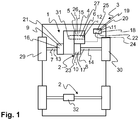
- Fig. 1 shows a motor vehicle 3 with a drive system 1 for driving a first wheel 29 and a second wheel 30 of a common axle 2 of the motor vehicle 3.
- the drive system 1 comprises an electric machine 4 as the drive unit 5, a drive shaft 6 driven by the drive unit 5, a first output shaft 7 and a second output shaft 8 as well as a first coupling 9 connecting the drive shaft 6 to the first output shaft 7 and a second coupling 10 connecting the drive shaft 6 to the second output shaft 8 and the two clutches 9, 10 and for determining speeds 12, 13, 14 of the drive shaft 6 and the two output shafts 7, 8.
- a drive system 1 is shown in which two clutches 9, 10 are provided on a common axle 2 of the motor vehicle 3, with one wheel 29, 30 of the motor vehicle 3 connected to the drive unit 5 of the motor vehicle 3 via each of the two clutches 9, 10 Is connected to transmit torque.
- the two clutches 9, 10 replace an otherwise common differential 32 (shown here on the other axle of the motor vehicle), by means of which different speeds of the wheels can be compensated.
- the calibration method relates to the regulation of the clutches 9, 10 of the drive system 1, so that they can be actuated at any time by a calibrated actuation pressure 21, 23. In this way, a first torque 15 provided by the drive unit 5 can be transmitted in the desired manner (and distribution) to the wheels 29, 30 of a common axle 2 of the motor vehicle 3.
- a calibration of the actuation pressure 16, 17, 21, 23 is also possible during the operation of the drive system 1.
- a first torque 15 is provided by the drive unit 5 and this is transmitted (proportionally) to the wheels 29, 30 on the basis of an existing operating point (which is defined, for example, by a request from a driver of the motor vehicle 3).
- a first torque 15 is provided on the drive unit 5.
- This can e.g. B. generated by the drive unit on the basis of a request from a driver of the motor vehicle 3.
- a first actuation pressure 16 for the first clutch 9 and a second actuation pressure 17 for the second clutch 10 are determined in the control unit 11 from a first characteristic map 18.
- the actuation pressures 16, 17 are intended to effect an operating point-dependent transmission and distribution of the first torque 15 to the output shafts 7, 8.
- the first torque 15 can also be divided up differently. Different actuation pressures 16, 17 can be stored in the first characteristic map 18 for different operating points and first torques 15, which are to be applied to the clutches 9, 10 for the transmission and, if necessary, the division of the first torque 15.
- a first actual differential speed 19 between the first output shaft 7 and the drive shaft 6 and a second actual differential speed 20 between the second output shaft 8 and the drive shaft 6 are determined.
- These actual differential speeds 19, 20 allow a conclusion to be drawn about the set and actually applied actuation pressures of the clutches 9, 10. If the actuation pressure is too high, the actual differential speed 19, 20 is "0" revolutions per minute. If the actuation pressure is too low, the actual differential speed 19, 20 will be not equal to "0" revolutions per minute and in particular be lower than a predetermined setpoint differential speed 22, 24.
- the drive shaft speed 12 is higher than the first speed 13 or second speed 14 of the respective output shaft 7, 8.
- the actual differential speeds 19, 20 as well as the speed of the drive unit 5 are determined via the control unit 11. This can determine the drive shaft speed 12 and the speeds 13, 14 of the output shafts 7, 8 via speed sensors.
- a setpoint differential speed 22, 24 between the output shafts 7, 8 and the drive shaft 6 is specified. This so-called micro-slip on the respective clutches 9, 10 makes it possible to determine exactly what kind of torque is transmitted in total via the clutches 9, 10. However, it is not possible to draw conclusions about the actual distribution of the first torque 15 to the clutches 9, 10.
- This setpoint differential speed 22, 24 is particularly dependent on the operating point and is present at a constant drive shaft speed 12 and constant speed 13, 14 of the output shafts 7, 8.
- the applied actuation pressures 16, 17 that are too high or too low correspond to a first torque 35 theoretically transmittable on the first clutch 9 (according to first characteristic map 18) and a second torque 36 theoretically transmittable on the second clutch 10 (according to first characteristic map 18).
- the sum of the theoretically transmittable torques 39 can accordingly have a deviation from the first torque 15 provided by the drive unit 5. This deviation can now be corrected by a calibration according to step d).
- step d) a first calibrated actuation pressure 21 for the first clutch 9 can be set until a first setpoint differential speed 22 is reached and a second calibrated actuation pressure 23 for the second clutch 10 is set until a second setpoint differential speed 24 is reached .
- the actuation pressure is therefore regulated up or down, taking into account the actual differential speed 19, 20 determined in step c), and is applied to the clutch 9, 10 is applied until a predetermined setpoint differential speed 22, 24 is present at the respective clutch 9, 10.
- a second characteristic map 25 is created taking into account the calibrated actuation pressures 21, 23 or the calibrated first torque on the drive unit 5.
- the second characteristic map 25 replaces in particular the first characteristic map 18, so that when the drive system 1 is subsequently actuated, even when steps a) and b) are carried out, the second characteristic map 25 can be accessed.
- the corrected actuation pressures from the newly created or second characteristic map 25 thus replace the actuation pressures 16, 17 from the first characteristic map 18.
- the first characteristic diagram 18 can be replaced by the second characteristic diagram 25, so that a new first characteristic diagram 18 is available.
- the second characteristic map 25 can be created by way of example and simply by multiplying first correction factors 40 for the first clutch 9 and second correction factors 41 for the second clutch 10 by the first characteristic map 18.
- the first torque 15 to be transmitted can be determined at least from the electric motor current 26 applied to the electric machine 4.
- At least one electrical motor current 26 and a motor speed 27 of the drive unit 5 are detected via the control unit 11.
- the motor speed 27 of the drive unit 5 can be determined via the drive shaft speed 12 of the drive shaft 6 or vice versa.
- Fig. 2 shows a sequence of the method. On the remarks too Fig. 1 is referred to.
- a first torque 15 is provided on the drive unit 5.
- step b) a first actuation pressure 16 for the first clutch 9 and a second actuation pressure 17 for the second clutch 10 are determined in the control unit 11 from a first characteristic map 18.
- step c) a first actual differential speed 19 between the first speed 13 of the first output shaft 7 and the drive shaft speed 12 of the drive shaft 6 and a second actual differential speed 20 between the second speed 14 of the second output shaft 8 and the drive shaft speed 12 of the drive shaft 6 determined.
- a setpoint differential speed 22, 24 between the output shafts 7, 8 and the drive shaft 6 is specified.
- a first calibrated actuation pressure 21 for the first clutch 9 can be set in step d) until a first setpoint differential speed 22 is reached, and a second calibrated actuation pressure 23 for the second clutch 10 can be set until a second setpoint differential speed 24 is reached.
- the actuation pressure is regulated up or down taking into account the actual differential speed 19, 20 determined in step c) and applied to the clutch 9, 10 until a predetermined target differential speed 22, 24 is present at the respective clutch 9, 10.
- step e a second characteristic map 25 is created taking into account the calibrated actuation pressures 21, 23 or the calibrated first torque on the drive unit 5.
- step f the first characteristic diagram 18 can be replaced by the second characteristic diagram 25, so that a new first characteristic diagram 18 is available.
- Fig. 3 shows a representation of the curves of the torques 34 over time 28 and the correction factors 33 during the method. On the remarks on the Fig. 1 and 2 is referred to.
- a first torque 15 is provided on the drive unit 5.
- step b) a first actuation pressure 16 for the first clutch 9 and a second actuation pressure 17 for the second clutch 10 are determined in the control unit 11 from a first characteristic map 18.
- the operating pressures 16, 17 applied which may be too high or too low, correspond to a first torque 35 theoretically transmittable on the first clutch 9 (initially higher than a first target torque 37 actually to be transmitted) and a second torque theoretically transmittable on the second clutch 10 36 (initially less than a second setpoint torque 38 that is actually to be transmitted).
- the sum of the theoretically transmittable torques 39 can accordingly have a deviation from the total setpoint torque. This deviation can be identified by calibrating the actuation pressures or the drive torque according to step d).
- step e) by creating a second characteristic map 25 (here in a very simple form by multiplying the first characteristic map 18 by the correction factor 40 for the first clutch 9 and correction factor 41 for the second clutch 10) a new first / second actuation pressure 16, 17 for step b) can be determined.
- the correction factors 40, 41 are iteratively determined in the context of step e), as shown, in order to obtain an adapted or second characteristic map 25.
- step e) begins as soon as the first torque 15 is to be transmitted to different degrees via the first clutch 9 and the second clutch 10 (first point in time 42).
- the target differential speeds 22, 24 according to steps a) to d
- the characteristics map is adapted exclusively for the more strongly activated clutch, so that the curve of the theoretically transmittable torque approaches the curve of the setpoint torque.
- the method is carried out in further intervals (third interval 46, fourth interval 47) as described above for the first two intervals 43, 45 until a deviation of the sum of the theoretically transmittable torques 39 from the first torque 15 is no longer present, or one The limit value falls below (i.e. the actual differential speeds 13, 14 can no longer be corrected).
- the first correction factor 40 corresponds to the ratio (quotient) of the first setpoint torque 37 and the theoretically transmittable first Torque 35.
- the second correction factor 41 corresponds to the ratio (quotient) of the second setpoint torque 38 and the theoretically transmittable second torque 36.
Landscapes
- Engineering & Computer Science (AREA)
- Mechanical Engineering (AREA)
- Transportation (AREA)
- Combustion & Propulsion (AREA)
- Chemical & Material Sciences (AREA)
- Automation & Control Theory (AREA)
- General Engineering & Computer Science (AREA)
- Human Computer Interaction (AREA)
- Physics & Mathematics (AREA)
- Fluid Mechanics (AREA)
- Arrangement And Driving Of Transmission Devices (AREA)
- Control Of Driving Devices And Active Controlling Of Vehicle (AREA)
- Hydraulic Clutches, Magnetic Clutches, Fluid Clutches, And Fluid Joints (AREA)
Claims (10)
- Procédé d'étalonnage d'un système d'entraînement en entrée (1) pour un essieu (2) d'un véhicule automobile (3), le système d'entraînement en entrée (1) comportant au moins une machine électrique (4) servant d'unité d'entraînement en entrée (5), un arbre d'entraînement en entrée (6) entraîné en entrée par l'unité d'entraînement en entrée (5), un premier arbre d'entraînement en sortie (7) et un deuxième arbre d'entraînement en sortie (8) ainsi qu'un premier embrayage (9) reliant l'arbre d'entraînement en entrée (6) au premier arbre d'entraînement en sortie (7) et un deuxième embrayage (10) reliant l'arbre d'entraînement en entrée (6) au deuxième arbre d'entraînement en sortie (8) et en outre une unité de commande (11) pour régler l'unité d'entraînement en entrée (5) et les embrayages (9, 10) ainsi que pour déterminer les vitesses de rotation (12, 13, 14) de l'arbre d'entraînement en entrée (6) et des arbres d'entraînement en sortie (7, 8) ; le procédé comportant au moins les étapes suivantes :a) mise à disposition d'un premier couple de rotation (15) au niveau de l'unité d'entraînement en entrée (5) pour un premier point de fonctionnement ;b) détermination d'une première pression d'actionnement (16) pour le premier embrayage (9), détermination d'une deuxième pression d'actionnement (17) pour le deuxième embrayage (10) à partir d'une première caractéristique (18) et application des pressions d'actionnement (16, 17) à la transmission en fonction du point de fonctionnement et répartition du premier couple de rotation (15) sur les arbres d'entraînement en sortie (7, 8) ;c) détermination d'une première vitesse de rotation différentielle réelle (19) entre la première vitesse de rotation (13) du premier arbre d'entraînement en sortie (7) et la vitesse de rotation d'arbre d'entraînement en entrée (12) de l'arbre d'entraînement en entrée (6) et une deuxième vitesse de rotation différentielle réelle (20) entre la deuxième vitesse de rotation (14) du deuxième arbre d'entraînement en sortie (8) et la vitesse de rotation d'arbre d'entraînement en entrée (12) de l'arbre d'entraînement en entrée (6) ;d) soit : réglage d'une première pression d'actionnement (21) étalonnée pour le premier embrayage (9) jusqu'à atteindre une première vitesse de rotation différentielle théorique (22) et réglage d'une deuxième pression d'actionnement (23) étalonnée pour le deuxième embrayage (10) jusqu'à atteindre une deuxième vitesse de rotation différentielle théorique (24) ;
soit : réglage d'un premier couple de rotation étalonné au niveau de l'unité d'entraînement en entrée (5) jusqu'à atteindre une première vitesse de rotation différentielle théorique (22) au niveau du premier embrayage (9) et une deuxième vitesse de rotation différentielle théorique (24) au niveau du deuxième embrayage (10) ;e) élaboration d'une deuxième caractéristique (25) en tenant compte des pressions d'actionnement (21, 23) étalonnées ou du premier couple de rotation étalonné au niveau de l'unité d'entraînement en entrée (5), soit la valeur la plus élevée des pressions d'actionnement (16, 17) étant d'abord modifiée soit les deux pressions d'actionnement (16, 17) étant modifiées simultanément dans une pondération dépendant de leur valeur. - Procédé selon la revendication 1, la première pression d'actionnement (16) appliquée à l'étape b) correspondant à un premier couple de rotation (35) pouvant être transmis sur le plan théorique au premier embrayage (9) et la deuxième pression d'actionnement (17) correspondant à un deuxième couple de rotation (36) pouvant être transmis sur le plan théorique au deuxième embrayage (10), l'étape c) permettant de détecter un écart entre un couple de rotation théorique sommaire à transmettre ensemble par les deux embrayages (9, 10) et un couple de rotation sommaire pouvant être transmis en théorie, ledit écart pouvant être corrigé par un réglage des pressions d'actionnement (21, 23) étalonnées ou du premier couple de rotation étalonné au niveau de l'essieu d'entraînement en entrée (5) selon l'étape d) et ledit écart étant pris en compte lors de l'élaboration de la deuxième caractéristique (25).
- Procédé selon l'une quelconque des revendications précédentes, au moins le premier embrayage (9) ou le deuxième embrayage (10) étant un embrayage actionné façon hydraulique ou de façon électrique.
- Procédé selon l'une quelconque des revendications précédentes, au moins un courant moteur électrique (26) et une vitesse de rotation du moteur (27) de l'unité d'entraînement en entrée étant détectés à l'aide de l'unité de commande (11).
- Procédé selon l'une quelconque des revendications précédentes, les étapes a) à e) étant réalisées en continu.
- Procédé selon l'une quelconque des revendications précédentes 1 à 4, les étapes a) à e) étant réalisées de façon périodique.
- Procédé selon la revendication 6, une période étant définie en fonction d'au moins un des paramètres suivants : le temps (28), la durée de fonctionnement du système d'entraînement en entrée, la sollicitation du système d'entraînement en entrée.
- Procédé selon l'une quelconque des revendications précédentes, respectivement une roue (29, 30) de l'essieu (2) commun du véhicule automobile (3) pouvant être reliée à l'unité d'entraînement en entrée (5) de façon à transmettre le couple de rotation par le biais de l'actionnement de chaque embrayage (9, 10).
- Procédé selon l'une quelconque des revendications précédentes, une boîte de vitesses (31) dotée d'une démultiplication variable étant disposée entre l'unité d'entraînement en entrée (5) et les arbres d'entraînement en sortie (7, 8).
- Véhicule automobile (3), comportant au moins un système d'entraînement en entrée (1) pour au moins un essieu (2) du véhicule automobile (3), le système d'entraînement en entrée (1) comportant au moins une machine électrique (4) prenant la forme d'une unité d'entraînement en entrée (5), un arbre d'entraînement en entrée (6) entraîné en entrée par l'unité d'entraînement en entrée (5), un premier arbre d'entraînement en sortie (7) et un deuxième arbre d'entraînement en sortie (8) ainsi qu'un premier embrayage (9) reliant l'arbre d'entraînement en entrée (6) au premier arbre d'entraînement en sortie (7) et un deuxième embrayage (10) reliant l'arbre d'entraînement en entrée (6) au deuxième arbre d'entraînement en sortie (8) et en outre une unité de commande (11) pour le réglage de l'unité d'entraînement en entrée (5) et des embrayages (9, 10) ainsi que pour déterminer les vitesses de rotation (12, 13, 14) de l'arbre d'entraînement en entrée (6) et des arbres d'entraînement en sortie (7, 8), le système d'entraînement en entrée (1) étant entraîné à l'aide d'un procédé selon l'une quelconque des revendications précédentes.
Priority Applications (1)
| Application Number | Priority Date | Filing Date | Title |
|---|---|---|---|
| PL17758829T PL3669097T3 (pl) | 2017-08-16 | 2017-08-16 | Sposób kalibracji układu napędowego dla osi pojazdu mechanicznego |
Applications Claiming Priority (1)
| Application Number | Priority Date | Filing Date | Title |
|---|---|---|---|
| PCT/EP2017/070762 WO2019034248A1 (fr) | 2017-08-16 | 2017-08-16 | Procédé d'étalonnage d'un système d'entrainement d'un essieu d'un véhicule automobile |
Publications (2)
| Publication Number | Publication Date |
|---|---|
| EP3669097A1 EP3669097A1 (fr) | 2020-06-24 |
| EP3669097B1 true EP3669097B1 (fr) | 2021-05-26 |
Family
ID=59745264
Family Applications (1)
| Application Number | Title | Priority Date | Filing Date |
|---|---|---|---|
| EP17758829.0A Active EP3669097B1 (fr) | 2017-08-16 | 2017-08-16 | Procédé d'étalonnage d'un système d'entrainement d'un essieu d'un véhicule automobile |
Country Status (6)
| Country | Link |
|---|---|
| US (1) | US11548519B2 (fr) |
| EP (1) | EP3669097B1 (fr) |
| JP (1) | JP6922075B2 (fr) |
| CN (1) | CN111201385B (fr) |
| PL (1) | PL3669097T3 (fr) |
| WO (1) | WO2019034248A1 (fr) |
Families Citing this family (2)
| Publication number | Priority date | Publication date | Assignee | Title |
|---|---|---|---|---|
| CN111746494B (zh) * | 2019-03-29 | 2021-06-11 | 上海汽车变速器有限公司 | 基于自学习的干式双离合器扭矩传递特性优化方法 |
| US12529421B2 (en) * | 2024-05-29 | 2026-01-20 | Caterpillar Inc. | Electric powertrain and method of calibration |
Family Cites Families (27)
| Publication number | Priority date | Publication date | Assignee | Title |
|---|---|---|---|---|
| JPH0747851A (ja) * | 1993-08-05 | 1995-02-21 | Honda Motor Co Ltd | 車両用動力伝達装置 |
| JP3319925B2 (ja) * | 1995-11-14 | 2002-09-03 | 本田技研工業株式会社 | 四輪駆動車両の動力伝達装置 |
| JP3612969B2 (ja) * | 1997-12-05 | 2005-01-26 | 三菱自動車工業株式会社 | 車両用駆動力調整装置 |
| JP3794544B2 (ja) * | 2000-03-22 | 2006-07-05 | ジヤトコ株式会社 | 電磁クラッチの締結制御装置 |
| DE10165097B3 (de) * | 2000-07-18 | 2015-07-23 | Schaeffler Technologies AG & Co. KG | Doppelkupplungsgetriebe |
| EP1253341A3 (fr) * | 2001-04-23 | 2004-04-07 | ZF Sachs AG | Système d'embrayage avec une installation d'embrayages multiples à actionnement hydraulique |
| JP2003278806A (ja) * | 2002-03-20 | 2003-10-02 | Mitsubishi Fuso Truck & Bus Corp | クラッチ制御装置 |
| CN100406894C (zh) * | 2002-04-10 | 2008-07-30 | 卢克摩擦片和离合器两合公司 | 用于确定部件转速、用于确定cvt变速器打滑及用于控制cvt变速器的方法以及锥盘-缠绕接触装置变速器 |
| CN100451403C (zh) * | 2004-07-28 | 2009-01-14 | 株式会社小松制作所 | 车辆的变速控制装置及变速控制方法 |
| DE102006029741B4 (de) * | 2005-06-29 | 2015-10-01 | Engineering Center Steyr Gmbh & Co. Kg | Verfahren zum Kalibrieren einer steuerbaren Reibungskupplung im Antriebsstrang eines Allradfahrzeuges |
| DE102006026188B4 (de) * | 2006-05-30 | 2008-02-28 | Getrag Driveline Systems Gmbh | Verfahren zum Verteilen von Antriebsmoment |
| DE102009000532A1 (de) * | 2009-02-02 | 2010-08-05 | Ford Global Technologies, LLC, Dearborn | Verfahren und Vorrichtung zur Ermittlung des Kupplungspunktes in einem Kraftfahrzeug |
| DE102009053885B4 (de) * | 2009-11-20 | 2015-10-29 | Getrag Getriebe- Und Zahnradfabrik Hermann Hagenmeyer Gmbh & Cie Kg | Verfahren zur Kisspointadaption |
| US8234946B2 (en) * | 2010-02-17 | 2012-08-07 | GM Global Technology Operations LLC | Hydraulic control system for a dual clutch transmission |
| CN104192016B (zh) * | 2010-03-31 | 2016-09-28 | 爱信艾达株式会社 | 控制装置 |
| CN102725163B (zh) * | 2010-03-31 | 2015-02-11 | 爱信艾达株式会社 | 控制装置 |
| JP5728181B2 (ja) * | 2010-09-03 | 2015-06-03 | Gknドライブラインジャパン株式会社 | 油圧クラッチ |
| DE112012001771A5 (de) * | 2011-04-20 | 2014-01-09 | Schaeffler Technologies AG & Co. KG | Verfahren zum Betrieb einer Brennkraftmaschine mit geteilter Kurbelwelle und Synchronkupplung zur Kopplung zweier Kurbelwellenteile einer Brennkraftmaschine |
| US8775044B2 (en) * | 2011-06-08 | 2014-07-08 | Ford Global Technologies, Llc | Clutch torque trajectory correction to provide torque hole filling during a ratio upshift |
| JP5553175B2 (ja) * | 2011-08-30 | 2014-07-16 | アイシン・エィ・ダブリュ株式会社 | 制御装置 |
| FR2992384B1 (fr) * | 2012-06-26 | 2014-07-04 | Borgwarner Inc | Transmission a double embrayage a huile |
| DE102013017226A1 (de) * | 2013-10-17 | 2015-04-23 | Getrag Getriebe- Und Zahnradfabrik Hermann Hagenmeyer Gmbh & Cie Kg | Kupplungseinrichtung, Verfahren zum Betrieb der Kupplungseinrichtung, sowie Antriebsstrang eines Kraftfahrzeuges mit der Kupplungseinrichtung und zur Durchführung des Verfahrens zum Betrieb der Kupplungseinrichtung |
| JP2015143544A (ja) * | 2014-01-31 | 2015-08-06 | スズキ株式会社 | クラッチ伝達トルク制御装置 |
| EP3126701B1 (fr) * | 2014-04-04 | 2020-07-15 | GKN Automotive Limited | Procédé de commande d'un système d'actionnement d'un embrayage, et système d'entraînement muni d'un système d'actionnement |
| JP6206320B2 (ja) | 2014-05-14 | 2017-10-04 | トヨタ自動車株式会社 | クラッチの制御装置 |
| DE102015005803A1 (de) | 2015-05-06 | 2016-11-10 | Daimler Ag | Verfahren zur Ansteuerung einer Formschlussschalteinheit |
| CN104976243B (zh) | 2015-07-17 | 2017-03-29 | 上海汽车变速器有限公司 | 湿式双离合器自动变速箱的预充油压力自适应方法及系统 |
-
2017
- 2017-08-16 EP EP17758829.0A patent/EP3669097B1/fr active Active
- 2017-08-16 WO PCT/EP2017/070762 patent/WO2019034248A1/fr not_active Ceased
- 2017-08-16 PL PL17758829T patent/PL3669097T3/pl unknown
- 2017-08-16 JP JP2020508626A patent/JP6922075B2/ja active Active
- 2017-08-16 CN CN201780095991.8A patent/CN111201385B/zh active Active
- 2017-08-16 US US16/638,500 patent/US11548519B2/en active Active
Non-Patent Citations (1)
| Title |
|---|
| None * |
Also Published As
| Publication number | Publication date |
|---|---|
| WO2019034248A1 (fr) | 2019-02-21 |
| PL3669097T3 (pl) | 2021-11-22 |
| US11548519B2 (en) | 2023-01-10 |
| CN111201385A (zh) | 2020-05-26 |
| US20200269860A1 (en) | 2020-08-27 |
| JP6922075B2 (ja) | 2021-08-18 |
| EP3669097A1 (fr) | 2020-06-24 |
| JP2020531342A (ja) | 2020-11-05 |
| CN111201385B (zh) | 2021-09-28 |
Similar Documents
| Publication | Publication Date | Title |
|---|---|---|
| EP2725252B1 (fr) | Procédé de détermination d'un paramètre de réglage pour un agencement d'actionneur hydraulique dans une chaîne cinématique de véhicule automobile | |
| DE112018007801B4 (de) | Verfahren zur regelung eines antriebssystems für eine achse eines kraftfahrzeuges und kraftfahrzeug | |
| DE102014007090B3 (de) | Verfahren zum Betreiben eines Antriebsstrangs für ein Kraftfahrzeug sowie entsprechender Antriebsstrang | |
| DE102013226611A1 (de) | Verfahren zum Betreiben einer Hybridantriebsvorrichtung | |
| DE102018126717A1 (de) | Steuersystem für ein stufenloses getriebe in einem fahrzeugantriebssystem | |
| EP1357309A2 (fr) | Méthode pour commander la procédure de démarrage d'une boíte de vitesse à double embrayage | |
| EP3805061A1 (fr) | Procédé de commande d'un embrayage d'un groupe d'entrainement d'un véhicule et/ou d'une machine, en particulier d'une chaine cinématique hybride d'un véhicule automobile | |
| DE102013016762B4 (de) | Verfahren zum Betreiben eines Triebstrangs für einen allradbetreibbaren Kraftwagen | |
| DE102015103985A1 (de) | Begrenzen eines Rekuperationsmoments für einen Hybridelektroantriebsstrang | |
| WO2019034248A1 (fr) | Procédé d'étalonnage d'un système d'entrainement d'un essieu d'un véhicule automobile | |
| DE102010018620A1 (de) | Verfahren zum Klassieren einer Kupplungseinheit | |
| EP2310717B1 (fr) | Procédé de fonctionnement d un système de transmission de couple et système de transmission de couple | |
| EP2576306A1 (fr) | Procédé pour faire fonctionner une chaîne cinématique | |
| DE102008020578A1 (de) | Verfahren zum Steuern einer Kupplungsanordnung | |
| EP3063032B1 (fr) | Procédé pour faire fonctionner un dispositif d'entraînement hybride et dispositif d'entraînement hybride correspondant | |
| DE102017009531B4 (de) | Verfahren zum Betreiben eines schlupfgeregelten Systems eines Antriebsstrangs für ein Kraftfahrzeug | |
| DE102015207312A1 (de) | Verfahren und Steuerungseinrichtung zum Betreiben eines Antriebsstrangs | |
| EP1632690B1 (fr) | Méthode pour déterminer la valeur de consigne de la pression pour contrôler un accouplement hydrodynamique | |
| DE102018221769A1 (de) | Verfahren zur Getriebesynchronisation eines Hybridfahrzeuges | |
| EP3215389B1 (fr) | Procédé de commande d'une transmission multiple d'un véhicule à moteur et transmission multiple correspondante | |
| DE102017203371A1 (de) | Verfahren zur Zustandsermittlung einer Kupplung im Kraftfahrzeug-Antriebsstrang, sowie zum Betrieb eines Hybridfahrzeug-Antriebsstrangs | |
| EP3550169B1 (fr) | Procédé de commande et / ou de régulation de l'embrayage double d'une boîte de vitesses à double embrayage d'un véhicule automobile | |
| DE102015011855A1 (de) | Verfahren zur Reibwertadaption bei einer Kupplung | |
| DE102022102673A1 (de) | Steuervorrichtung und verfahren zur steuerung der synchronisierung einer elektrischen maschine | |
| DE102024206398A1 (de) | Verfahren zur Durchführung eines Anfahrvorganges bei einem Kraftfahrzeug |
Legal Events
| Date | Code | Title | Description |
|---|---|---|---|
| STAA | Information on the status of an ep patent application or granted ep patent |
Free format text: STATUS: UNKNOWN |
|
| STAA | Information on the status of an ep patent application or granted ep patent |
Free format text: STATUS: THE INTERNATIONAL PUBLICATION HAS BEEN MADE |
|
| PUAI | Public reference made under article 153(3) epc to a published international application that has entered the european phase |
Free format text: ORIGINAL CODE: 0009012 |
|
| STAA | Information on the status of an ep patent application or granted ep patent |
Free format text: STATUS: REQUEST FOR EXAMINATION WAS MADE |
|
| 17P | Request for examination filed |
Effective date: 20200304 |
|
| AK | Designated contracting states |
Kind code of ref document: A1 Designated state(s): AL AT BE BG CH CY CZ DE DK EE ES FI FR GB GR HR HU IE IS IT LI LT LU LV MC MK MT NL NO PL PT RO RS SE SI SK SM TR |
|
| AX | Request for extension of the european patent |
Extension state: BA ME |
|
| DAV | Request for validation of the european patent (deleted) | ||
| DAX | Request for extension of the european patent (deleted) | ||
| GRAP | Despatch of communication of intention to grant a patent |
Free format text: ORIGINAL CODE: EPIDOSNIGR1 |
|
| STAA | Information on the status of an ep patent application or granted ep patent |
Free format text: STATUS: GRANT OF PATENT IS INTENDED |
|
| INTG | Intention to grant announced |
Effective date: 20201216 |
|
| GRAS | Grant fee paid |
Free format text: ORIGINAL CODE: EPIDOSNIGR3 |
|
| GRAA | (expected) grant |
Free format text: ORIGINAL CODE: 0009210 |
|
| STAA | Information on the status of an ep patent application or granted ep patent |
Free format text: STATUS: THE PATENT HAS BEEN GRANTED |
|
| AK | Designated contracting states |
Kind code of ref document: B1 Designated state(s): AL AT BE BG CH CY CZ DE DK EE ES FI FR GB GR HR HU IE IS IT LI LT LU LV MC MK MT NL NO PL PT RO RS SE SI SK SM TR |
|
| REG | Reference to a national code |
Ref country code: GB Ref legal event code: FG4D Free format text: NOT ENGLISH |
|
| REG | Reference to a national code |
Ref country code: CH Ref legal event code: EP |
|
| REG | Reference to a national code |
Ref country code: DE Ref legal event code: R096 Ref document number: 502017010480 Country of ref document: DE |
|
| REG | Reference to a national code |
Ref country code: AT Ref legal event code: REF Ref document number: 1396523 Country of ref document: AT Kind code of ref document: T Effective date: 20210615 |
|
| REG | Reference to a national code |
Ref country code: IE Ref legal event code: FG4D Free format text: LANGUAGE OF EP DOCUMENT: GERMAN |
|
| REG | Reference to a national code |
Ref country code: LT Ref legal event code: MG9D |
|
| PG25 | Lapsed in a contracting state [announced via postgrant information from national office to epo] |
Ref country code: BG Free format text: LAPSE BECAUSE OF FAILURE TO SUBMIT A TRANSLATION OF THE DESCRIPTION OR TO PAY THE FEE WITHIN THE PRESCRIBED TIME-LIMIT Effective date: 20210826 Ref country code: HR Free format text: LAPSE BECAUSE OF FAILURE TO SUBMIT A TRANSLATION OF THE DESCRIPTION OR TO PAY THE FEE WITHIN THE PRESCRIBED TIME-LIMIT Effective date: 20210526 Ref country code: FI Free format text: LAPSE BECAUSE OF FAILURE TO SUBMIT A TRANSLATION OF THE DESCRIPTION OR TO PAY THE FEE WITHIN THE PRESCRIBED TIME-LIMIT Effective date: 20210526 Ref country code: LT Free format text: LAPSE BECAUSE OF FAILURE TO SUBMIT A TRANSLATION OF THE DESCRIPTION OR TO PAY THE FEE WITHIN THE PRESCRIBED TIME-LIMIT Effective date: 20210526 |
|
| REG | Reference to a national code |
Ref country code: NL Ref legal event code: MP Effective date: 20210526 |
|
| PG25 | Lapsed in a contracting state [announced via postgrant information from national office to epo] |
Ref country code: SE Free format text: LAPSE BECAUSE OF FAILURE TO SUBMIT A TRANSLATION OF THE DESCRIPTION OR TO PAY THE FEE WITHIN THE PRESCRIBED TIME-LIMIT Effective date: 20210526 Ref country code: RS Free format text: LAPSE BECAUSE OF FAILURE TO SUBMIT A TRANSLATION OF THE DESCRIPTION OR TO PAY THE FEE WITHIN THE PRESCRIBED TIME-LIMIT Effective date: 20210526 Ref country code: PT Free format text: LAPSE BECAUSE OF FAILURE TO SUBMIT A TRANSLATION OF THE DESCRIPTION OR TO PAY THE FEE WITHIN THE PRESCRIBED TIME-LIMIT Effective date: 20210927 Ref country code: NO Free format text: LAPSE BECAUSE OF FAILURE TO SUBMIT A TRANSLATION OF THE DESCRIPTION OR TO PAY THE FEE WITHIN THE PRESCRIBED TIME-LIMIT Effective date: 20210826 Ref country code: LV Free format text: LAPSE BECAUSE OF FAILURE TO SUBMIT A TRANSLATION OF THE DESCRIPTION OR TO PAY THE FEE WITHIN THE PRESCRIBED TIME-LIMIT Effective date: 20210526 Ref country code: IS Free format text: LAPSE BECAUSE OF FAILURE TO SUBMIT A TRANSLATION OF THE DESCRIPTION OR TO PAY THE FEE WITHIN THE PRESCRIBED TIME-LIMIT Effective date: 20210926 Ref country code: GR Free format text: LAPSE BECAUSE OF FAILURE TO SUBMIT A TRANSLATION OF THE DESCRIPTION OR TO PAY THE FEE WITHIN THE PRESCRIBED TIME-LIMIT Effective date: 20210827 |
|
| PG25 | Lapsed in a contracting state [announced via postgrant information from national office to epo] |
Ref country code: NL Free format text: LAPSE BECAUSE OF FAILURE TO SUBMIT A TRANSLATION OF THE DESCRIPTION OR TO PAY THE FEE WITHIN THE PRESCRIBED TIME-LIMIT Effective date: 20210526 |
|
| PG25 | Lapsed in a contracting state [announced via postgrant information from national office to epo] |
Ref country code: SK Free format text: LAPSE BECAUSE OF FAILURE TO SUBMIT A TRANSLATION OF THE DESCRIPTION OR TO PAY THE FEE WITHIN THE PRESCRIBED TIME-LIMIT Effective date: 20210526 Ref country code: SM Free format text: LAPSE BECAUSE OF FAILURE TO SUBMIT A TRANSLATION OF THE DESCRIPTION OR TO PAY THE FEE WITHIN THE PRESCRIBED TIME-LIMIT Effective date: 20210526 Ref country code: EE Free format text: LAPSE BECAUSE OF FAILURE TO SUBMIT A TRANSLATION OF THE DESCRIPTION OR TO PAY THE FEE WITHIN THE PRESCRIBED TIME-LIMIT Effective date: 20210526 Ref country code: DK Free format text: LAPSE BECAUSE OF FAILURE TO SUBMIT A TRANSLATION OF THE DESCRIPTION OR TO PAY THE FEE WITHIN THE PRESCRIBED TIME-LIMIT Effective date: 20210526 Ref country code: CZ Free format text: LAPSE BECAUSE OF FAILURE TO SUBMIT A TRANSLATION OF THE DESCRIPTION OR TO PAY THE FEE WITHIN THE PRESCRIBED TIME-LIMIT Effective date: 20210526 Ref country code: RO Free format text: LAPSE BECAUSE OF FAILURE TO SUBMIT A TRANSLATION OF THE DESCRIPTION OR TO PAY THE FEE WITHIN THE PRESCRIBED TIME-LIMIT Effective date: 20210526 Ref country code: ES Free format text: LAPSE BECAUSE OF FAILURE TO SUBMIT A TRANSLATION OF THE DESCRIPTION OR TO PAY THE FEE WITHIN THE PRESCRIBED TIME-LIMIT Effective date: 20210526 |
|
| REG | Reference to a national code |
Ref country code: DE Ref legal event code: R097 Ref document number: 502017010480 Country of ref document: DE |
|
| REG | Reference to a national code |
Ref country code: CH Ref legal event code: PL |
|
| PLBE | No opposition filed within time limit |
Free format text: ORIGINAL CODE: 0009261 |
|
| STAA | Information on the status of an ep patent application or granted ep patent |
Free format text: STATUS: NO OPPOSITION FILED WITHIN TIME LIMIT |
|
| PG25 | Lapsed in a contracting state [announced via postgrant information from national office to epo] |
Ref country code: MC Free format text: LAPSE BECAUSE OF FAILURE TO SUBMIT A TRANSLATION OF THE DESCRIPTION OR TO PAY THE FEE WITHIN THE PRESCRIBED TIME-LIMIT Effective date: 20210526 |
|
| REG | Reference to a national code |
Ref country code: BE Ref legal event code: MM Effective date: 20210831 |
|
| PG25 | Lapsed in a contracting state [announced via postgrant information from national office to epo] |
Ref country code: LI Free format text: LAPSE BECAUSE OF NON-PAYMENT OF DUE FEES Effective date: 20210831 Ref country code: CH Free format text: LAPSE BECAUSE OF NON-PAYMENT OF DUE FEES Effective date: 20210831 |
|
| 26N | No opposition filed |
Effective date: 20220301 |
|
| PG25 | Lapsed in a contracting state [announced via postgrant information from national office to epo] |
Ref country code: IS Free format text: LAPSE BECAUSE OF FAILURE TO SUBMIT A TRANSLATION OF THE DESCRIPTION OR TO PAY THE FEE WITHIN THE PRESCRIBED TIME-LIMIT Effective date: 20210926 Ref country code: LU Free format text: LAPSE BECAUSE OF NON-PAYMENT OF DUE FEES Effective date: 20210816 Ref country code: AL Free format text: LAPSE BECAUSE OF FAILURE TO SUBMIT A TRANSLATION OF THE DESCRIPTION OR TO PAY THE FEE WITHIN THE PRESCRIBED TIME-LIMIT Effective date: 20210526 |
|
| PG25 | Lapsed in a contracting state [announced via postgrant information from national office to epo] |
Ref country code: IT Free format text: LAPSE BECAUSE OF FAILURE TO SUBMIT A TRANSLATION OF THE DESCRIPTION OR TO PAY THE FEE WITHIN THE PRESCRIBED TIME-LIMIT Effective date: 20210526 Ref country code: IE Free format text: LAPSE BECAUSE OF NON-PAYMENT OF DUE FEES Effective date: 20210816 Ref country code: BE Free format text: LAPSE BECAUSE OF NON-PAYMENT OF DUE FEES Effective date: 20210831 |
|
| PG25 | Lapsed in a contracting state [announced via postgrant information from national office to epo] |
Ref country code: CY Free format text: LAPSE BECAUSE OF FAILURE TO SUBMIT A TRANSLATION OF THE DESCRIPTION OR TO PAY THE FEE WITHIN THE PRESCRIBED TIME-LIMIT Effective date: 20210526 |
|
| PG25 | Lapsed in a contracting state [announced via postgrant information from national office to epo] |
Ref country code: HU Free format text: LAPSE BECAUSE OF FAILURE TO SUBMIT A TRANSLATION OF THE DESCRIPTION OR TO PAY THE FEE WITHIN THE PRESCRIBED TIME-LIMIT; INVALID AB INITIO Effective date: 20170816 |
|
| PG25 | Lapsed in a contracting state [announced via postgrant information from national office to epo] |
Ref country code: MK Free format text: LAPSE BECAUSE OF FAILURE TO SUBMIT A TRANSLATION OF THE DESCRIPTION OR TO PAY THE FEE WITHIN THE PRESCRIBED TIME-LIMIT Effective date: 20210526 |
|
| PG25 | Lapsed in a contracting state [announced via postgrant information from national office to epo] |
Ref country code: MT Free format text: LAPSE BECAUSE OF FAILURE TO SUBMIT A TRANSLATION OF THE DESCRIPTION OR TO PAY THE FEE WITHIN THE PRESCRIBED TIME-LIMIT Effective date: 20210526 |
|
| PGFP | Annual fee paid to national office [announced via postgrant information from national office to epo] |
Ref country code: GB Payment date: 20240822 Year of fee payment: 8 |
|
| PGFP | Annual fee paid to national office [announced via postgrant information from national office to epo] |
Ref country code: FR Payment date: 20240823 Year of fee payment: 8 |
|
| PGFP | Annual fee paid to national office [announced via postgrant information from national office to epo] |
Ref country code: AT Payment date: 20240819 Year of fee payment: 8 |
|
| PGFP | Annual fee paid to national office [announced via postgrant information from national office to epo] |
Ref country code: PL Payment date: 20240805 Year of fee payment: 8 |
|
| PGFP | Annual fee paid to national office [announced via postgrant information from national office to epo] |
Ref country code: DE Payment date: 20250819 Year of fee payment: 9 |
|
| PG25 | Lapsed in a contracting state [announced via postgrant information from national office to epo] |
Ref country code: TR Free format text: LAPSE BECAUSE OF FAILURE TO SUBMIT A TRANSLATION OF THE DESCRIPTION OR TO PAY THE FEE WITHIN THE PRESCRIBED TIME-LIMIT Effective date: 20210526 |
|
| PG25 | Lapsed in a contracting state [announced via postgrant information from national office to epo] |
Ref country code: AT Free format text: LAPSE BECAUSE OF NON-PAYMENT OF DUE FEES Effective date: 20250816 |
|
| REG | Reference to a national code |
Ref country code: AT Ref legal event code: MM01 Ref document number: 1396523 Country of ref document: AT Kind code of ref document: T Effective date: 20250816 |
|
| GBPC | Gb: european patent ceased through non-payment of renewal fee |
Effective date: 20250816 |