EP3669111B1 - Verschlussvorrichtung - Google Patents
Verschlussvorrichtung Download PDFInfo
- Publication number
- EP3669111B1 EP3669111B1 EP18742949.3A EP18742949A EP3669111B1 EP 3669111 B1 EP3669111 B1 EP 3669111B1 EP 18742949 A EP18742949 A EP 18742949A EP 3669111 B1 EP3669111 B1 EP 3669111B1
- Authority
- EP
- European Patent Office
- Prior art keywords
- closure device
- sealing
- transmission
- axis
- central axis
- Prior art date
- Legal status (The legal status is an assumption and is not a legal conclusion. Google has not performed a legal analysis and makes no representation as to the accuracy of the status listed.)
- Active
Links
Images


Classifications
-
- F—MECHANICAL ENGINEERING; LIGHTING; HEATING; WEAPONS; BLASTING
- F16—ENGINEERING ELEMENTS AND UNITS; GENERAL MEASURES FOR PRODUCING AND MAINTAINING EFFECTIVE FUNCTIONING OF MACHINES OR INSTALLATIONS; THERMAL INSULATION IN GENERAL
- F16L—PIPES; JOINTS OR FITTINGS FOR PIPES; SUPPORTS FOR PIPES, CABLES OR PROTECTIVE TUBING; MEANS FOR THERMAL INSULATION IN GENERAL
- F16L55/00—Devices or appurtenances for use in, or in connection with, pipes or pipe systems
- F16L55/10—Means for stopping flow in pipes or hoses
- F16L55/11—Plugs
- F16L55/1108—Plugs fixed by screwing or by means of a screw-threaded ring
-
- F—MECHANICAL ENGINEERING; LIGHTING; HEATING; WEAPONS; BLASTING
- F16—ENGINEERING ELEMENTS AND UNITS; GENERAL MEASURES FOR PRODUCING AND MAINTAINING EFFECTIVE FUNCTIONING OF MACHINES OR INSTALLATIONS; THERMAL INSULATION IN GENERAL
- F16L—PIPES; JOINTS OR FITTINGS FOR PIPES; SUPPORTS FOR PIPES, CABLES OR PROTECTIVE TUBING; MEANS FOR THERMAL INSULATION IN GENERAL
- F16L55/00—Devices or appurtenances for use in, or in connection with, pipes or pipe systems
- F16L55/10—Means for stopping flow in pipes or hoses
- F16L55/11—Plugs
- F16L55/1125—Plugs fixed by rotating a limited amplitude
-
- F—MECHANICAL ENGINEERING; LIGHTING; HEATING; WEAPONS; BLASTING
- F16—ENGINEERING ELEMENTS AND UNITS; GENERAL MEASURES FOR PRODUCING AND MAINTAINING EFFECTIVE FUNCTIONING OF MACHINES OR INSTALLATIONS; THERMAL INSULATION IN GENERAL
- F16L—PIPES; JOINTS OR FITTINGS FOR PIPES; SUPPORTS FOR PIPES, CABLES OR PROTECTIVE TUBING; MEANS FOR THERMAL INSULATION IN GENERAL
- F16L57/00—Protection of pipes or objects of similar shape against external or internal damage or wear
- F16L57/005—Protection of pipes or objects of similar shape against external or internal damage or wear specially adapted for the ends of pipes
Definitions
- the invention relates to a closure device for closing a pipe, with a carrier element, at least one sealing contact surface, a closure device center axis and at least one actuating device with at least one adjusting element.
- the adjusting element can be moved from a first position to a second position relative to the carrier element, with the closure device being in a sealing position in the second position of the adjusting element.
- the adjusting element is pivotable or rotatable relative to the carrier element about an actuation axis, which is arranged tilted by a maximum of 10 ° to the closure device center axis.
- Such a closure device is used, for example, to close pipes used to build pipelines.
- the sealing contact surface lies against the pipe surface in a position in which the pipe is closed by the closure device. In this position, the center axis of the closure device coincides with the longitudinal center axis of the pipe.
- a locking device is approximately from the DE 10 2009 017 975 A1 known.
- the disclosed closure device is partially inserted into the interior of the tube by inserting it in the axial direction of the tube. After insertion into the pipe, the sealing contact surface lies completely flat on the inner surface of the pipe at.
- a collar of the closure device which is pronounced in the radial direction, rests on the end face of the pipe that is to be connected to another pipe. In order to ensure adequate tightness of the closure, the sealing contact surface must be in contact with the inner surface of the pipe with a minimum surface pressure.
- one closure device is inserted into each opening of a pipe.
- the intermediate closure space designed in this way is intended to be protected from the ingress of rainwater and foreign bodies and thus specifically to prevent corrosion on the pipe surface adjacent to the closure space.
- the closure device With this design of the closure device, an immense amount of force is required to insert it into the pipe.
- the radial surface pressure between the sealing contact surface and the inner surface of the pipe which is necessary for sufficient sealing, leads to a high axial force, which is necessary to push the closure device into the pipe and causes a lot of effort during assembly.
- a further disadvantageous effect of insertion is the friction between the sealing contact surface and the inner surface of the pipe, whereby at least the softer of the two contact partners is scratched by the other.
- This impairment of the surface properties has a negative impact on the tightness of the closure, particularly when the closure device is inserted several times.
- the closure device can be used through the collar and the adjoining cylinder jacket-shaped section limited to open pipe ends, which run straight at least in a first section. Experience has also shown that the collar makes it more difficult for liquid to drain from the area of the face of the pipe and thus promotes corrosion in the area.
- a known closure device is from the DE 20 2015 002 284 U1 known. This closure device is moved into the sealing position using a screw.
- the object of the present invention is to provide a closure element that can be installed easily and quickly with the most reliable seal possible.
- the object is achieved by a closure device according to claim 1, wherein the actuating device comprises an eccentric element.
- the eccentric element can be pivoted about the actuation axis.
- a sliding surface of the eccentric element facing away from the actuation axis has a varying distance from the actuation axis.
- the actuating device serves to transmit or translate the movement of the adjusting element to bring about the sealing position of the closure device.
- the carrier element serves to support the actuating device.
- the carrier element is preferably annular and is designed to run around the central axis of the closure device.
- the closure device has several, in particular two, carrier elements. At least one component of the actuating device lies between two support elements. This allows the actuating device to be protected particularly effectively from environmental influences, which increases its reliability.
- both the inner tube surface and the sealing contact surface preferably have a circular cross section when viewed in a plane orthogonal to the closure device center axis.
- the closure device center axis cuts a cross-section through the sealing contact surface at a point in which the straight line that connects the two most distant points of the sealing contact surface in cross section intersects the straight line the two least points of the sealing contact surface that are distant from one another in cross section.
- the closure device is only brought into the sealing position at the location where it is also intended to remain in the sealing position, the assembly and the sealing quality of the closure device are improved.
- the closure device is positioned within the pipe to be closed while the adjusting element is in its first position and a lower surface pressure than the minimum surface pressure acts on the inner wall of the pipe due to the sealing contact surface. Due to the low axial resistance force due to the low or lack of surface pressure, the closure device can be positioned anywhere and with only little effort within the tube with a corresponding inner diameter, which makes assembly much easier.
- a particularly secure seal is then guaranteed, since the sealing surface was previously only slightly modified by the friction on the inner surface of the pipe. In the sealing position, the sealing contact surface and the inner pipe surface are not moved relative to one another, making the seal particularly reliable.
- the adjusting element can be pivoted or rotated relative to the carrier element about an actuation axis.
- the actuation axis is tilted by a maximum of 10° to the locking device center axis.
- the adjusting element preferably has the shape of a lever to be folded or a screw, whereby the rotational movement is superimposed on a translational movement.
- the locking device is particularly ergonomic to operate for the installer who transfers the adjusting element.
- Rotation around the actuation axis which is essentially parallel to the central axis of the closure device, can be carried out particularly safely, since the closure device forms a counterforce that ensures the secure position of the closure device by resting the sealing contact surface on the inner surface of the pipe.
- the shape of the movement initiation ensures the quick assembly of closure elements according to the invention even when the fitter repeatedly transfers them into the sealing position.
- the adjusting element can be displaced relative to the carrier element parallel to the actuation axis. Due to the axial displacement from its first position to its second position, it is possible to transfer a plurality of adjusting elements into the second position particularly easily at the same time. When using an appropriate tool, the fitter is able to simultaneously transfer the adjusting elements in parallel by simply applying force in the axial direction, which speeds up assembly.
- the actuating device comprises an eccentric element.
- the eccentric element is pivotable about the actuation axis and has a sliding surface which faces away from the actuation axis and is at a varying distance from the actuation axis.
- the sliding surface preferably has an extension parallel to the actuation axis.
- the sliding surface runs at least partially around the actuation axis with a varying radius.
- the sliding surface serves to move another element of the closure device in this direction, whereby the closure device is brought into the sealing position.
- the eccentric element translates a rotational movement about the actuation axis into a translational movement.
- the actuation device comprises a thrust element which is movable parallel to the actuation axis.
- the thrust element also has a sliding surface facing away from the actuation axis with a varying distance from the actuation axis.
- the distance of the sliding surface from the actuation axis varies at least in the axial direction.
- the axial movement of the thrust element causes a movement in the radial direction of a further element of the closure device resting on the sliding surface.
- the variable slope of the sliding surface offers the possibility of producing sufficient surface pressure on the sealing contact surface using a relatively low force applied by the fitter, which in turn makes assembly easier.
- the actuation device comprises, instead of the thrust element, a cone element with the sliding surface which faces away from the actuation axis and has a varying distance from the actuation axis.
- the cone element is designed axially symmetrical to the actuation axis.
- the use of such a cone element enables the desired translation, whereby a movement with a rotational and translational component parallel to the actuation axis is translated into a purely translational movement in the radial direction.
- the use of the cone element instead of the thrust element simplifies the construction of the closure device in that it generates a translational movement that is independent of its own rotation. Due to the simplified storage, the function of the closure device is particularly reliable and its sealing is particularly reliable.
- the translation is preferably self-locking.
- the eccentric, thrust or cone element is actively moved directly or indirectly by the adjusting element, whereby an element resting on the sliding surface can be moved. However, a movement of the component resting on the other sliding surface does not cause any movement of the eccentric, thrust or cone element.
- Both the eccentric and the cone element are preferably arranged adjacent to the adjusting element and fixed thereto. This reduces the friction within the actuating device to a minimum.
- the adjusting element is formed in one piece with the eccentric, thrust or cone element. This reduces the number of components subject to wear and increases the reliability of the locking device.
- the closure device comprises at least one transmission element, which is displaced from the first to the second position by the transfer of the adjusting element. It is displaced translationally and parallel to a transmission axis.
- the transmission element serves to transmit the force acting on the closure device to produce the required surface pressure of the sealing contact surface.
- the transmission element is at least partially arranged in a groove or a gap in the carrier element and each transmission element is assigned to an adjustment element. This form of mobility makes the transmission element particularly resistant to wear.
- the transmission element enables reliable transmission of the force applied to create the sealing position and thus ensures reliable sealing of the pipe.
- the transmission axis is preferably tilted by 80° to 100° relative to the closure device center axis. It is spaced from the closure device center axis by a maximum of one fifth of the smallest distance between the sealing contact surface and the closure device center axis.
- a force applied to the adjusting element can be transferred particularly easily to the sealing contact surface and the distance between the sealing contact surface and the adjusting element can be bridged in the shortest possible way.
- the transmission axis is arranged parallel to the closure device center axis. Because the transmission element is moved parallel to the closure device center axis, the surface pressure of the at least one sealing contact surface can be increased by moving a smaller number of transmission elements. The seal is particularly secure due to the completely more homogeneous force applied to the sealing contact surface. At the same time, the possible reduction in the number of transmission elements while maintaining a completely more homogeneous surface pressure structure results in a particularly high level of reliability of the closure device.
- the transmission element is arranged adjacent to the sliding surface and is moved by the movement of the sliding element. Since the area of the transmission element which rests on the sliding surface cannot follow its movement due to its limited mobility, the transmission element slides on the sliding surface with friction while the adjusting element is transferred from its first position to its second position. The distance between the transmission element increases Actuation axis to the extent that the distance of the sliding surface from the actuation axis increases in the direction of the transmission axis. Due to the direct contact of the transmission element on the sliding surface, only a minimum number of elements is required for the closure device, which reduces the probability of failure of the closure device.
- the gradient of the change in distance of the sliding surface ie the change in distance per angle (eccentric element) or per path in the axial direction (thrust element or cone element), determines the translation with which the movement of the adjusting element is converted into the movement of the transition element.
- This design of the closure device according to the invention creates a particularly simple form of motion translation.
- the particularly simple structure increases the reliability of the seal.
- the sliding surface is preferably shaped in such a way that the movable connection between the transmission element and the sliding surface is self-locking. Specifically, this means that although the transmission element can be moved by a movement of the sliding surface, the other way around the sliding surface cannot be moved by a movement of the transmission element. Due to this self-locking mechanism, any securing element that locks the actuating device in the sealing position is not necessary, which in turn increases the process reliability of the sealing through the closure device.
- At least one guide arrangement is arranged between the carrier element and the transmission element, which controls the movement of the transmission element parallel to the direction of transmission.
- the guide arrangement ensures an exact displacement of the transmission element in the desired direction of movement and thus a particularly homogeneous increase in the surface pressure of the sealing contact surface within the pipe interior when the adjusting element is transferred from its first to its second position.
- the guide arrangement prevents the transmission element from tilting within the carrier element. This simplifies assembly and makes the closing process more reliable.
- the closure device preferably comprises at least three transmission elements, each with at least one pressing surface, which faces away from the closure device center axis.
- the pressing surface In the sealing position of the closure element, the pressing surface deviates from an imaginary circular cylinder lateral surface by a maximum of one fifth of the radius of the circular cylinder lateral surface.
- the axis of symmetry of the circular cylinder surface coincides with the center axis of the closure device.
- the pressing surface faces the inner surface of the pipe and the transmission elements are movable in a radial direction relative to the closure device center axis. It is the surface of the transmission element that is furthest away from the closure device center axis.
- the pressing surface In the sealing position, the pressing surface either lies directly against the inner surface of the pipe or exerts pressure on it indirectly via another adjacent component of the closure device.
- the pressing surfaces preferably have a circular-arc-shaped cross section when viewed in the direction of the closure device center axis in order to be opposite a Pipe inner surface with a circular cross section to form a particularly homogeneous surface pressure. If the pressing surface lies directly against the inner surface of the pipe in the sealing position within the pipe, the circular cylinder surface coincides with the inner surface of the pipe.
- At least three transmission elements are particularly advantageous because this number of transmission elements allows any portion of the circumference of the closure device to be formed or force to be applied to the sealing contact surface.
- the advantage of the pressing surfaces shaped in this way is the possibility of a particularly homogeneous surface pressure on the sealing contact surface, whereby a particularly reliable seal is achieved.
- the pressing surface preferably has a recess corresponding to the shape of this element in order to position this element particularly reliably.
- the pressing surfaces of the transmission elements are arranged to extend completely around the closure device center axis when viewed in the direction of the closure device center axis. This serves to ensure that it sits flush against the inner surface of the pipe in the circumferential direction.
- the pressing surfaces of the transmission elements are spaced apart from one another in the tangential direction by a maximum of one tenth of their minimum distance from the closure device center axis.
- the pressing surfaces together form a total pressing surface enclosing the closure device center axis, which has at most small interruptions and the distance from the closure device center axis can be changed uniformly and is maximum in the sealing position.
- the possibility of fully “contracting” the transmission elements makes assembly of the closure device much easier. While the adjusting element is arranged in the first position and the pressing surfaces have a smaller radius than in the sealing position, the closure device can be easily moved within the tube in the axial direction. During the subsequent transfer of the closure device into the sealing position, all pressing surfaces are moved radially in the direction of the inner surface of the pipe, as a result of which wear on the sealing contact surface is minimal.
- the adjusting element when the adjusting element is in the first position when the transmission elements are viewed in the direction of the closure device center axis, two adjacent transmission elements each have a side section superimposed on one another.
- the superimposition of the side sections makes it possible that in the sealing position, in which the total pressing surface has its maximum radius, there are only slight gaps between two adjacent ones in the tangential direction Pressing surfaces arise.
- the transmission axes of the transmission elements are preferably each oriented radially relative to the closure device center axis, when the transmission elements move in the direction of the closure device center axis, their side sections overlap in order to enable a closed overall pressing surface in the sealing position.
- the movement of the transmission elements relative to one another causes them to converge, which is reflected in the superimposition of the side sections.
- the largely gap-free formation of the overall pressing surface in the sealing position which is made possible in this way, enables a particularly reliable sealing of the pipe by the closure device.
- the transmission elements preferably have two side sections which delimit a central section.
- the thickness of the side sections measured in the direction of the closure device center axis is at least a third, in particular half, of the thickness of the central section less than its thickness.
- the mutually facing side sections of two transmission elements are positioned so that they adjoin one another in the axial direction, at least when the adjusting element is in the first position. As the total pressing area circumference grows when the closure device is moved into the sealing position, the side sections shift relative to one another in such a way that the area in which they overlap decreases.
- the adjusting element can be moved from the first to the second position by a movement in a direction tilted by 70 to 110 ° relative to the closure device center axis.
- This form of movement of the adjusting element translates it particularly easily into a radial pressure on the sealing contact surface, since the direction of movement of the adjusting element and the direction with which the surface pressure of the sealing contact surface acts can be arranged in one plane with respect to one another.
- This enables simple movement translation and thus high reliability of the locking device.
- the direction of movement of the adjusting element is essentially directly parallel to the effective direction of the surface pressure of the sealing contact surface. The surface pressure can therefore be generated directly by moving the adjusting element, which enables the simplest possible construction of the closure device and thus increases its reliability.
- the adjusting element and the transmission element are in one piece in this embodiment.
- energy is released by at least one energy storage device when the adjusting element reaches the second position.
- This energy is used to create the sealing position.
- the energy storage is preferably a spring, which is in a tensioned state as long as the adjusting element is arranged in its first position. When the adjustment element reaches the second position, the spring is released and the stored energy is released.
- the force exerted by the energy storage causes surface pressure on the sealing contact surface.
- This embodiment of the closure device can be installed particularly easily and quickly, since the installer does not have to apply any force to generate the necessary surface pressure in the closure device.
- the energy accumulator can also be adjusted in such a way that a homogeneous surface pressure of optimal size is achieved, which ensures a particularly reliable seal.
- the closure device preferably comprises a sealing element which has the sealing contact surface.
- the sealing element therefore rests directly on the inner surface of the pipe in the sealing position.
- the optimal materials can be used for both the sealing element and the elements of the actuating device and the renewal of the sealing contact surface can be simplified.
- an elastic material can be used for the sealing element for reliable contact with the inner surface of the pipe, while stiffer materials are used for force-transmitting elements of the actuating device. This separation of the closure device components optimizes their function and the effort required for each replacement and thus ensures sealing is particularly reliable.
- the closure device preferably has exactly one sealing element, which is designed as an annular seal that runs around the center axis of the closure device.
- This sealing element has at least one sealing contact surface.
- the ring seal lies fully against the inner surface of the pipe, as a result of which the at least one sealing contact surface essentially has the shape of a sealing contact surface.
- the ring seal can be designed both as a cross seal and as a sealing ring with a substantially round cross section in the relaxed state.
- a cross seal preferably has two sealing contact surfaces in the sealing position.
- the sealing element has a larger outer radius than the carrier element at every point along the circumference of the closure device, so that only the sealing element has contact with the inner surface of the pipe.
- the advantage of the ring seal is a particularly process-reliable seal in that the only one sealing element creates a sealing contact surface that completely encircles the center axis of the closure device and has a constant width due to the constant cross section of the sealing element.
- the sealing element rests at least partially on the transmission element in the sealing position.
- the force generating the necessary surface pressure is transferred directly from the transmission element to the sealing element.
- This form of transmission reduces the risk of failure of the closure device and therefore makes the seal particularly reliable. If the transmission element can be moved translationally, parallel to the center axis of the closure device, the surface pressure is achieved by squeezing the sealing element in the axial direction. A part of the sealing element is displaced in the radial direction by the force of the transmission element.
- the carrier element consists predominantly of a fiber-reinforced polymer composite, in particular a polypropylene-glass fiber composite.
- This material ensures sufficient stability of the support element.
- the choice of material ensures that the support element is light. This simplifies the assembly of the closure element, while the stability enables a reliable seal.
- the closure device preferably has an optical indicator which shows the position of the adjustment element. By visually identifying the position, the fitter can see from a greater distance whether the closure device has been moved to the sealing position. This enables quick control of the assembly, especially since the indicator also provides closure devices from outside the pipe that are spaced from the end face of the pipe can be controlled.
- the optical indicator is a colored area of the adjustment or transmission element. Which only becomes visible through a recess in the closure device when the sealing position is at least partially achieved.
- a plurality of such indicators can preferably be provided distributed in the circumferential direction, with each adjustment element preferably being assigned an indicator.
- a gas and water vapor permeable membrane is preferably arranged on the carrier element, which allows gas and water vapor to pass through the closure device.
- the membrane is particularly preferably arranged centrally in the closure device, so that the closure device center axis intersects the membrane.
- the membrane is preferably injected into the carrier element during production or screwed to the carrier element.
- the gas passage made possible by the membrane ensures that the interior of the pipe located between the closure devices is ventilated when the closed pipe is stored in the environment. The possibility of air escaping from this space prevents a pressure gradient from forming between the closed pipe interior and the surroundings, which would cause an axial force to act on the closure device. This axial force could displace the closure device relative to the inner surface of the pipe and thus endanger the reliable seal.
- the membrane preferably withstands a water column of at least 100 mm and is impermeable to dust particles with a diameter of more than six micrometers. This means that the interior of the pipe is particularly effectively protected against the ingress of liquids and foreign bodies.
- the membrane is preferably open to diffusion and, in conjunction with a high heat capacity of the tube, enables the formation of a microclimate within the interior of the tube.
- temperature fluctuations relative to the surroundings take place with a delay and the temperature never drops below the dew point, since before the dew point is reached, the relative humidity decreases due to air exchange with the surroundings.
- Handles are particularly preferably arranged on the carrier element. Using these handles, the fitter can position the locking device to be installed particularly easily within the pipe.
- Fig. 1 shows a closure device 2 for closing a pipe in a perspective view.
- the closure device 2 has a carrier element 4 and a sealing contact surface 6.
- a closure device center axis 8 cuts the closure device 2 at its center.
- the outer radius of the closure device 2 is constant along its circumference.
- the closure device 2 has an adjusting element 10, which, among other things, is in the Fig. 3c , 5b , 6b , 8a as well as 8b is shown.
- This adjusting element 10 can be moved from a first position to a second position relative to the carrier element 4.
- the adjusting element 10 of the embodiment shown is in its respective first position.
- the Fig. 2a , 6b and 8b show the adjusting elements 10 of the same exemplary embodiments in their second position.
- the closure device 2 In the second position of the adjusting element 10, the closure device 2 is in its sealing position. In the sealing position, the sealing contact surface 6 lies within a tube with a corresponding one when the closure device 2 is located Diameter on the inner surface of the pipe and acts on it with a minimum surface pressure. Outside the tube, the sealing position of the closure device 2 is characterized by the fact that the sealing contact surface 6 of the closure device 2 is at the maximum distance from the closure device center axis 8.
- the adjusting element 10 can be pivoted relative to the carrier element 4 about an actuation axis 12 (first, second and fourth embodiments) or rotatable (third embodiment).
- the actuating device comprises an eccentric element 14 which is pivotable about the actuating axis 12.
- the eccentric element 14 has a sliding surface 16 facing away from the actuation axis 12, which has a varying distance from the actuation axis 12.
- the actuating device comprises a cone element 18, which in the third embodiment according to Fig. 5a, 5b , 6a and 6b is shown.
- the cone element 18 can be moved parallel to the actuation axis 12.
- the cone element 18 also has a sliding surface 16 facing away from the actuation axis 12, which has a varying distance from the actuation axis 12.
- the Fig. 2a , 5b and 8a show a transmission element 22, which is displaced translationally, parallel to a transmission axis 20, by transferring the adjusting element 10 from the first to the second position.
- the transmission element is located on the Sliding surface and is spaced from the actuation axis by its rotation.
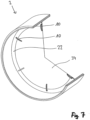
- the transmission axis 20 is in the embodiments according to Fig. 2a and 5b arranged orthogonally to the closure device center axis 8. It differs from this in the fourth exemplary embodiment according to Fig. 7 , 8a and 8b arranged parallel to the closure device center axis 8.
- the Fig. 2a, 2b and 4 show a guide arrangement 24 through which the transmission element 22 is guided relative to the carrier element 4 parallel to the transmission axis 20.
- the guide arrangement includes, on the one hand, an elongated hole in the transmission element and, on the other hand, a guide pin of the carrier element.
- the embodiment of the closure device 2 according to the invention according to Figs. 2a and 2b has four transmission elements 22, the embodiment according to 8a and 8b a transmission element 22.
- the four transmission elements 22 of the first mentioned embodiment each have a pressing surface 26 facing away from the closure device center axis 8, which in the sealing position of the closure element 10 are arranged in an imaginary circular cylindrical surface, the axis of symmetry of which coincides with the closure device center axis 8.
- the pressing surfaces 26 run completely around the closure device center axis 8 or the closure device 2 itself.
- the pressing surface from the transmission element into the Fig. 7 and 8th is, however, arranged perpendicular to the closure device center axis and one transmission element is axially displaceable.
- the adjacent transmission elements 22 each overlap one another with a side section 28 in the axial direction. Between two side sections 28 there is a middle section 30.
- the thickness of the side sections 28 measured in the direction of the closure device center axis 8 is half the thickness of the middle section 30 less than its thickness. The adjacent side sections can thus engage one another while reducing the pressing surface radius.
- the closure device 2 has a sealing element 32 (see in particular Fig. 3c and Fig. 8a ).
- the sealing element 32 is an annular seal running around the closure device center axis 8 and in the embodiment according to Fig. 3c two sealing contact surfaces as a cross seal.
- the ones in the through 8a and 8b The ring seal shown in the illustrated embodiments, on the other hand, has a round cross section and only one sealing contact surface 6. Regardless of the shape of the sealing element 32, it lies on the transmission element 22 (see e.g. Fig. 8a ) or the transmission elements 22 (see e.g. Fig. 2a or 5b ) at.
- the closure device 2 has a gas-permeable membrane 34 arranged on the carrier element 4, which serves to enable the passage of gas through the closure device 2.
- Fig. 4 shows an optical indicator 36 on the adjusting element 10.
- This is a colored area of the surface of the adjusting element 10, which is moved when the adjusting element is transferred from the first to the second position. As a result of the movement, the colored area is transferred from a position in which it is covered by the carrier element to a position in which it is congruent with a recess in the carrier element 4 encompassed by the optical indicator 36.
- Fig. 1 These recesses are shown on one half of the carrier element 4. This optical indicator 36 thus indicates the position of the adjusting element to the outside.
Landscapes
- Engineering & Computer Science (AREA)
- General Engineering & Computer Science (AREA)
- Mechanical Engineering (AREA)
- Pipe Accessories (AREA)
- Pressure Vessels And Lids Thereof (AREA)
- Sealing Devices (AREA)
- Operating, Guiding And Securing Of Roll- Type Closing Members (AREA)
- Gasket Seals (AREA)
- Quick-Acting Or Multi-Walled Pipe Joints (AREA)
Description
- Die Erfindung betrifft eine Verschlussvorrichtung zum Verschließen eines Rohres, mit einem Trägerelement, zumindest einer Dichtkontaktfläche, einer Verschlussvorrichtungsmittelachse und zumindest einer Betätigungsvorrichtung mit mindestens einem Verstellelement. Das Verstellelement ist relativ zum Trägerelement aus einer ersten Position in eine zweite Position überführbar, wobei in der zweiten Position des Verstellelementes die Verschlussvorrichtung sich in einer Dichtstellung befindet. Das Verstellelement ist relativ zum Trägerelement um eine Betätigungsachse schwenkbar oder drehbar, die höchstens um 10° zur Verschlussvorrichtungsmittelachse verkippt angeordnet ist.
- Eine derartige Verschlussvorrichtung wird beispielsweise zum Verschließen von zum Bau von Pipelines verwendeten Rohren genutzt. Die Dichtkontaktfläche liegt in einer Stellung, in der das Rohr von der Verschlussvorrichtung verschlossen wird, an der Rohroberfläche an. Die Verschlussvorrichtungsmittelachse fällt in dieser Stellung mit der Längsmittelachse des Rohres zusammen.
- Eine Verschlussvorrichtung ist etwa aus der
DE 10 2009 017 975 A1 bekannt. Die offenbarte Verschlussvorrichtung wird durch Einschieben in die axiale Richtung des Rohres teilweise in dessen Rohrinnenraum eingebracht. Nach der Einbringung in das Rohr liegt die Dichtkontaktfläche vollumfänglich flächig an der Rohrinnenfläche an. Ein in radialer Richtung ausgeprägter Kragen der Verschlussvorrichtung liegt dabei an der mit einem weiteren Rohr zu verbindenden Stirnfläche des Rohres an. Um eine ausreichende Dichtheit des Verschlusses gewährleisten zu können, muss die Dichtkontaktfläche mit einer Mindestflächenpressung an der Rohrinnenfläche anliegen. - In der Regel wird je eine Verschlussvorrichtung in beide Öffnungen eines Rohres eingesetzt. Der so ausgebildete, zwischenliegende Verschlussraum soll dadurch vor dem Eindringen von Regenwasser und Fremdkörpern geschützt werden und somit im Einzelnen Korrosion an der an den Verschlussraum angrenzenden Rohroberfläche verhindert werden.
- Bei dieser Ausführung der Verschlussvorrichtung ist zu deren Einsatz in das Rohr ein immenser Kraftaufwand nötig. Die für die ausreichende Dichtheit nötige radiale Flächenpressung zwischen Dichtkontaktfläche und Rohrinnenfläche führt zu einer hohen axialen Kraft, die zum Einschieben der Verschlussvorrichtung in das Rohr nötig ist und einen hohen Aufwand bei der Montage verursacht. Eine weitere nachteilige Auswirkung des Einschiebens hat die Reibung von Dichtkontakt- und Rohrinnenfläche aufeinander, wodurch zumindest der weichere der beiden Kontaktpartner durch den jeweils anderen zerkratzt wird. Diese Beeinträchtigung der Oberflächeneigenschaften beeinflusst die Dichtheit des Verschlusses insbesondere bei mehrmaligem Einsetzen der Verschlussvorrichtung negativ. Durch den Kragen und den sich daran anschließenden zylindermantelförmigen Abschnitt ist der Einsatz der Verschlussvorrichtung begrenzt auf offene Rohrenden, welche zumindest in einem ersten Abschnitt gerade verlaufen. Die Erfahrung hat außerdem gezeigt, dass der Kragen den Abfluss von Flüssigkeit aus dem Bereich der Stirnseite des Rohres erschwert und somit Korrosion in dem Bereich fördert.
- Eine bekannte Verschlussvorrichtung ist aus der
DE 20 2015 002 284 U1 bekannt. Diese Verschlussvorrichtung wird mittels eine Schraube in die Dichtstellung überführt. - Weitere bekannte Verschlussvorrichtungen der eingangs genannten Art sind aus der
FR 2 769 351 A1 US 2009/0301568 A1 und derGB 2 110 653 A - Aufgabe der vorliegenden Erfindung ist die Bereitstellung eines einfach und schnell montierbaren Verschlusselementes mit einer möglichst prozesssicheren Abdichtung.
- Erfindungsgemäß wird die Aufgabe durch eine Verschlussvorrichtung nach dem Anspruch 1, wobei die Betätigungsvorrichtung ein Exzenterelement umfasst.
- Das Exzenterelement ist um die Betätigungsachse schwenkbar. Eine von der Betätigungsachse abgewandte Gleitoberfläche des Exzenterelementes hat einen variierenden Abstand von der Betätigungsachse. Befindet sich die Verschlussvorrichtung innerhalb des Rohres mit einem zur Verschlussvorrichtung korrespondierenden Durchmesser, zeichnet sich die Dichtstellung dadurch aus, dass die Dichtkontaktfläche an der Rohrinnenfläche anliegt und zumindest mit einer Mindestflächenpressung auf die Rohroberfläche einwirkt. Befindet sich die Verschlussvorrichtung dagegen nicht innerhalb eines Rohres, zeichnet sich die Dichtstellung dadurch aus, dass in ihr die Dichtkontaktfläche einen größeren Abstand zur Verschlussvorrichtungsmittelachse hat als vor Erreichen der Dichtstellung.
- Die Betätigungsvorrichtung dient der Übertragung bzw. Übersetzung der Bewegung des Verstellelementes zur Herbeiführung der Dichtstellung der Verschlussvorrichtung. Das Trägerelement dient der Abstützung der Betätigungsvorrichtung. Dabei ist das Trägerelement vorzugsweise ringförmig und um die Verschlussvorrichtungsmittelachse umlaufend ausgebildet. In einer vorteilhaften Ausgestaltung der Erfindung weist die Verschlussvorrichtung mehrere, insbesondere zwei Trägerelemente auf. Zumindest ein Bestandteil der Betätigungsvorrichtung liegt dabei zwischen zwei Trägerelementen. Dadurch kann die Betätigungsvorrichtung besonders wirksam vor Umwelteinflüssen geschützt werden, was ihre Zuverlässigkeit erhöht.
- Befindet sich die Verschlussvorrichtung innerhalb des Rohres in Dichtstellung, fällt die Verschlussvorrichtungsmittelachse mit der Rohrlängsmittelachse zusammen. Sowohl die Rohrinnenfläche als auch die Dichtkontaktfläche haben bevorzugt in einer zur Verschlussvorrichtungsmittelachse orthogonalen Ebene betrachtet einen kreisrunden Querschnitt.
- Hat die Dichtkontaktfläche einen davon abweichenden Querschnitt, insbesondere einen elliptischen Querschnitt, schneidet die Verschlussvorrichtungsmittelachse einen Querschnitt durch die Dichtkontaktfläche in einem Punkt, in dem die Gerade, die die beiden am weitesten voneinander entfernten Punkte der Dichtkontaktfläche im Querschnitt miteinander verbindet, die Gerade schneidet, die die beiden am wenigsten voneinander entfernten Punkte der Dichtkontaktfläche im Querschnitt miteinander verbindet.
- Dadurch, dass die Verschlussvorrichtung erst an dem Ort in die Dichtstellung gebracht wird, an dem sie auch in Dichtstellung verweilen soll, ist die Montage sowie auch die Dichtqualität der Verschlussvorrichtung verbessert. Die Verschlussvorrichtung wird, während sich das Verstellelement in seiner ersten Position befindet und durch die Dichtkontaktfläche eine geringere Flächenpressung als die Mindestflächenpressung auf die Rohrinnenwand wirkt, innerhalb des zu verschließenden Rohres positioniert. Durch die aufgrund der geringen bzw. fehlenden Flächenpressung geringen axialen Widerstandskraft kann die Verschlussvorrichtung an beliebiger Stelle und mit nur geringem Kraftaufwand innerhalb des Rohres mit einem korrespondierenden Innendurchmesser positioniert werden, was die Montage wesentlich erleichtert. In Dichtstellung ist anschließend eine besonders sichere Abdichtung gewährleistet, da die Dichtfläche zuvor nur höchstens unwesentlich durch die Reibung an der Rohrinnenfläche modifiziert wurde. In der Dichtstellung werden die Dichtkontaktfläche und die Rohrinnenfläche nicht relativ zueinander bewegt, wodurch die Abdichtung besonders prozesssicher ist.
- Das Verstellelement ist relativ zum Trägerelement um eine Betätigungsachse schwenkbar oder drehbar. Die Betätigungsachse ist höchstens um 10° zur Verschlussvorrichtungsmittelachse verkippt. Das Verstellelement hat bevorzugt die Form eines umzulegenden Hebels oder die einer Schraube, wodurch sich die Rotationsbewegung mit einer translatorischen Bewegung überlagert. Durch die Rotation des Verstellelementes um die Betätigungsachse ist die Verschlussvorrichtung für den einbauenden Monteur, der das Verstellelement überführt, besonders ergonomisch zu bedienen. Insbesondere die erfindungsgemäße
- Rotation um die zur Verschlussvorrichtungsmittelachse im Wesentlichen parallele Betätigungsachse ist dabei besonders sicher durchführbar, da die Verschlussvorrichtung durch Aufliegen der Dichtkontaktfläche auf der Rohrinnenfläche eine den sicheren Stand der Verschlussvorrichtung gewährleistende Gegenkraft ausbildet. Durch die Form der Bewegungseinleitung wird die schnelle Montage von erfindungsgemäßen Verschlusselementen auch bei wiederholter Überführung dieser durch den Monteur in die Dichtstellung gewährleistet.
- In einer zur Erfindung alternativen und nicht beanspruchten Ausführungsform ist das Verstellelement relativ zum Trägerelement parallel zur Betätigungsachse verschiebbar. Durch die axiale Verschiebung von seiner ersten Position in seine zweite Position ist es möglich, eine Mehrzahl an Verstellelementen besonders einfach gleichzeitig in die zweite Position zu überführen. Dem Monteur wird bei der Nutzung eines entsprechenden Werkzeugs die gleichzeitige, parallele Überführung der Verstellelemente durch eine einfache Krafteinleitung in axialer Richtung ermöglicht, was die Montage beschleunigt. Erfindungsgemäß umfasst die Betätigungsvorrichtung ein Exzenterelement. Das Exzenterelement ist um die Betätigungsachse schwenkbar und hat eine Gleitoberfläche, welche von der Betätigungsachse abgewandt ist und von der Betätigungsachse einen variierenden Abstand hat. Die Gleitoberfläche hat vorzugsweise eine zur Betätigungsachse parallele Erstreckung. Die Gleitoberfläche verläuft mit einem variierenden Radius zumindest teilweise um die Betätigungsachse. Durch das Schwenken des Exzenterelementes verändert sich in einer relativ zur Betätigungsachse ortsfesten, radialen Richtung der Abstand von der Gleitoberfläche des Exzenterelementes zur Betätigungsachse. Die Gleitoberfläche dient der Bewegung eines weiteren Elementes der Verschlussvorrichtung in diese Richtung, wodurch die Verschlussvorrichtung in Dichtstellung gebracht wird. Durch das Exzenterelement wird eine Rotationsbewegung um die Betätigungsachse in eine translatorische Bewegung übersetzt. Durch diese Bewegungsübersetzung kann die gewünschte Flächenpressung der Dichtkontaktfläche, welche in der Dichtstellung der Verschlussvorrichtung nötig ist, durch eine Kraft in radialer Richtung hergestellt werden, wobei in das Verstellelement verhältnismäßig nur eine erheblich geringere Kraft bzw. ein geringeres Drehmoment eingebracht werden muss. Dadurch nimmt die Belastung des Monteurs ab und die Montage wird vereinfacht.
- In einer zur Erfindung alternativen und nicht beanspruchten Ausgestaltung umfasst die Betätigungsvorrichtung ein Schubelement, das parallel zur Betätigungsachse bewegbar ist. Das Schubelement weist ebenfalls eine von der Betätigungsachse abgewandte Gleitoberfläche mit einem variierenden Abstand von der Betätigungsachse auf. Der Abstand der Gleitoberfläche von der Betätigungsachse variiert dabei zumindest in axialer Richtung. Durch die axiale Bewegung des Schubelementes wird eine Bewegung in radialer Richtung von einem an der Gleitoberfläche anliegenden weiteren Element der Verschlussvorrichtung bewirkt. Wiederum bietet die variable Steigung der Gleitoberfläche die Möglichkeit, durch eine verhältnismäßig geringe Krafteinwirkung durch den Monteur eine ausreichende Flächenpressung der Dichtkontaktfläche herzustellen, wodurch die Montage wiederum erleichtert wird.
- In einer weiteren alternativen und nicht benaspruchten Ausgestaltung umfasst die Betätigungsvorrichtung statt des Schubelementes ein Konuselement mit der Gleitoberfläche, die von der Betätigungsachse abgewandt ist und einen variierenden Abstand von der Betätigungsachse hat. Das Konuselement ist achsensymmetrisch zur Betätigungsachse ausgebildet. Die Verwendung eines solchen Konuselementes ermöglicht die gewünschte Übersetzung, wobei eine Bewegung mit rotatorischem und translatorischem Anteil parallel zur Betätigungsachse in eine rein translatorische Bewegung in radialer Richtung übersetzt wird. Die Verwendung des Konuselementes statt des Schubelementes vereinfacht den Aufbau der Verschlussvorrichtung insofern, als dass es eine translatorische Bewegung erzeugt, die unabhängig von einer eigenen Rotation ist. Durch die somit vereinfachte Lagerung ist die Funktion der Verschlussvorrichtung besonders zuverlässig und dessen Abdichtung besonders prozesssicher.
- Je nach Steigung der Gleitoberfläche relativ zur Betätigungsachse ist die Übersetzung vorzugsweise selbsthemmend. Aktiv bewegt wird dabei das Exzenter-, das Schub- oder das Konuselement mittel- oder unmittelbar durch das Verstellelement, wodurch ein an der Gleitoberfläche anliegendes Element bewegt werden kann. Eine Bewegung des anderen Gleitoberfläche anliegenden Bauteils verursacht hingegen keine Bewegung des Exzenter-, Schub- oder Konuselements. Sowohl das Exzenterals auch das Konuselement sind vorzugsweise am Verstellelement anliegend angeordnet und daran fixiert. Dadurch wird die Reibung innerhalb der Betätigungsvorrichtung auf ein Mindestmaß reduziert.
- Besonders bevorzugt ist das Verstellelement mit dem Exzenter-, dem Schub- oder dem Konuselement einstückig ausgebildet. Dadurch wird die Anzahl der verschleißbehafteten Bauteile reduziert und die Zuverlässigkeit der Verschlussvorrichtung erhöht.
- Erfindungsgemäß umfasst die Verschlussvorrichtung zumindest ein Übertragungselement, welches durch die Überführung des Verstellelementes von der ersten in die zweite Position verlagert wird. Dabei wird es translatorisch und parallel zu einer Übertragungsachse verlagert. Das Übertragungselement dient zur Übertragung der auf die Verschlussvorrichtung einwirkenden Kraft zur Herstellung der erforderlichen Flächenpressung der Dichtkontaktfläche. Bevorzugt ist das Übertragungselement zumindest teilweise in einer Nut bzw. einem Spalt des Trägerelementes angeordnet und jedes Übertragungselement einem Verstellelement zugeordnet. Durch diese Form der Beweglichkeit ist das Übertragungselement besonders verschleißunanfällig. Das Übertragungselement ermöglicht eine zuverlässige Übertragung der eingebrachten Kraft zur Herstellung der Dichtstellung und sorgt somit für die prozesssichere Abdichtung des Rohres.
- Bevorzugt ist die Übertragungsachse relativ zur Verschlussvorrichtungsmittelachse um 80° bis 100° verkippt. Dabei ist sie höchstens um ein Fünftel des kleinsten Abstandes der Dichtkontaktfläche zur Verschlussvorrichtungsmittelachse von der Verschlussvorrichtungsmittelachse beabstandet. Durch die bezüglich der Verschlussvorrichtungsmittelachse im Wesentlichen radial ausgerichtete Übertragungsachse ist eine auf das Verstellelement eingebrachte Kraft besonders einfach auf die Dichtkontaktfläche übertragbar und der Abstand zwischen Dichtkontaktfläche und Verstellelement auf kürzestmöglichem Weg überbrückbar. Durch die Übertragung der Kraft auf dem kürzesten Weg wird das Ausfallrisiko der Verschlussvorrichtung minimiert und die Montage vereinfacht.
- In einer alternativen und nicht beanspruchten Ausgestaltung der Erfindung ist die Übertragungsachse parallel zur Verschlussvorrichtungsmittelachse angeordnet. Dadurch, dass das Übertragungselement parallel zur Verschlussvorrichtungsmittelachse bewegt wird, kann die Flächenpressung der zumindest einen Dichtkontaktfläche durch eine Bewegung von einer kleineren Zahl von Übertragungselementen erhöht werden. Durch die so ermöglichte vollumfänglich homogenere Krafteinwirkung auf die Dichtkontaktfläche ist die Abdichtung besonders sicher. Gleichzeitig wird durch die mögliche Reduktion die Anzahl an Übertragungselementen bei Erhalt eines vollumfänglich homogeneren Flächenpressungsaufbaus eine besonders große Ausfallsicherheit der Verschlussvorrichtung erreicht.
- Besonders bevorzugt ist das Übertragungselement an der Gleitoberfläche anliegend angeordnet und wird durch die Bewegung des Gleitelementes bewegt. Da der Bereich des Übertragungselementes, welcher an der Gleitoberfläche anliegt, deren Bewegung aufgrund seiner eingeschränkten Beweglichkeit nicht folgen kann, kommt es zu einem reibungsbehafteten Gleiten des Übertragungselementes auf der Gleitoberfläche, während das Verstellelement aus seiner ersten Position in seine zweite Position überführt wird. Dabei wächst der Abstand des Übertragungselementes von der Betätigungsachse in dem Maß, wie auch der Abstand der Gleitoberfläche von der Betätigungsachse in Richtung der Übertragungsachse anwächst. Durch das unmittelbare Anliegen vom Übertragungselement an der Gleitoberfläche wird nur eine Mindestanzahl von Elementen für die Verschlussvorrichtung benötigt, wodurch die Ausfallwahrscheinlichkeit der Verschlussvorrichtung reduziert wird. Der Gradient der Abstandsänderung der Gleitoberfläche, d. h. die Abstandsänderung pro Winkel (Exzenterelement) oder pro Weg in axialer Richtung (Schubelement bzw. Konuselement), bestimmt die Übersetzung, mit der die Bewegung des Verstellelementes in die Bewegung des Übergangselementes umgeformt wird. Durch diese Ausführung der erfindungsgemäßen Verschlussvorrichtung existiert eine besonders einfache Form der Bewegungsübersetzung. Der besonders einfache Aufbau erhöht die Zuverlässigkeit der Abdichtung. Vorzugsweise ist die Gleitoberfläche so ausgeformt, dass die bewegliche Verbindung von Übertragungselement und Gleitoberfläche selbsthemmend ist. Im Einzelnen bedeutet das, dass zwar das Übertragungselement durch eine Bewegung der Gleitoberfläche bewegt werden kann, jedoch anders herum die Gleitoberfläche nicht durch eine Bewegung des Übertragungselementes bewegt werden kann. Ein etwaiges die Betätigungsvorrichtung in Dichtstellung feststellendes Sicherungselement ist aufgrund dieser Selbsthemmung nicht nötig, wodurch wiederum die Prozesssicherheit der Abdichtung durch die Verschlussvorrichtung erhöht ist.
- Vorzugsweise ist zwischen dem Trägerelement und dem Übertragungselement zumindest eine Führungsanordnung angeordnet, die die Bewegung des Übertragungselementes parallel zur Übertragungsrichtung führt. Die Führungsanordnung gewährleistet eine exakte Verlagerung des Übertragungselementes in die gewünschte Bewegungsrichtung und damit innerhalb des Rohrinnenraumes bei Überführung des Verstellelementes von seiner ersten in seine zweite Position eine besonders homogene Erhöhung der Flächenpressung der Dichtkontaktfläche. Die Führungsanordnung verhindert etwa ein Verkanten des Übertragungselementes innerhalb des Trägerelementes. Sowohl die Montage wird dadurch vereinfacht als auch der Vorgang der Verschließens prozesssicherer.
- Bevorzugt umfasst die Verschlussvorrichtung mindestens drei Übertragungselemente mit jeweils zumindest einer Pressfläche, welche von der Verschlussvorrichtungsmittelachse abgewandt ist. Die Pressfläche weicht in der Dichtstellung des Verschlusselementes von einer gedachten Kreiszylindermantelfläche um höchstens ein Fünftel des Radius der Kreiszylindermantelfläche ab. Die Symmetrieachse der Kreiszylindermantelfläche fällt dabei mit der Verschlussvorrichtungsmittelachse zusammen. Die Pressfläche ist in der Dichtstellung bei Befinden der Verschlussvorrichtung innerhalb des Rohrinnenraumes der Rohrinnenfläche zugewandt und die Übertragungselemente in relativ zur Verschlussvorrichtungsmittelachse radialer Richtung bewegbar. Sie ist die am weitesten von der Verschlussvorrichtungsmittelachse beabstandete Oberfläche des Übertragungselementes. In Dichtstellung liegt die Pressfläche entweder unmittelbar an der Rohrinnenfläche an oder übt mittelbar, über ein anliegendes weiteres Bauteil der Verschlussvorrichtung, eine Pressung darauf aus. Die Pressflächen haben vorzugsweise bei Betrachtung in Richtung der Verschlussvorrichtungsmittelachse einen kreisbogenförmigen Querschnitt, um gegenüber einer Rohrinnenfläche mit einem kreisrunden Querschnitt eine besonders homogene Flächenpressung auszubilden. Liegt die Pressfläche in der Dichtstellung innerhalb des Rohres unmittelbar an der Rohrinnenfläche an, fällt die Kreiszylindermantelfläche mit der Rohrinnenfläche zusammen. Zumindest drei Übertragungselemente sind besonders vorteilhaft, da durch diese Anzahl an Übertragungselementen ein beliebiger Anteil des Umfangs der Verschlussvorrichtung ausgebildet bzw. Kraft auf die Dichtkontaktfläche aufgebracht werden kann. Vorteil der so geformten Pressflächen ist die Möglichkeit einer besonders homogenen Flächenpressung der Dichtkontaktfläche, wodurch eine besonders zuverlässige Abdichtung erreicht wird.
- Befindet sich in der Dichtstellung der Verschlussvorrichtung innerhalb des Rohrinnenraumes ein weiteres Element der Verschlussvorrichtung zwischen Pressfläche und Rohrinnenfläche, weist die Pressfläche vorzugsweise eine mit der Form dieses Elementes korrespondierende Vertiefung auf, um dieses Element besonders zuverlässig zu positionieren.
- Besonders bevorzugt sind die Pressflächen der Übertragungselemente bei Betrachtung in Richtung der Verschlussvorrichtungsmittelachse vollumfänglich um die Verschlussvorrichtungsmittelachse verlaufend angeordnet. Das dient der in Umfangsrichtung vollumfänglichen und bündigen Anlage an die Rohrinnenfläche. Die Pressflächen der Übertragungselemente sind in der Dichtstellung der Verschlussvorrichtung in tangentialer Richtung maximal um ein Zehntel ihres minimalen Abstandes zur Verschlussvorrichtungsmittelachse voneinander beabstandet. Somit wird in der Dichtstellung durch die Pressflächen vollumfänglich eine Kraft auf die Rohrinnenfläche wirksam, entweder unmittelbar oder bei einem zwischen Pressfläche und Rohrinnenfläche angeordneten weiteren Element mittelbar.
- Die Pressflächen bilden zusammen eine die Verschlussvorrichtungsmittelachse umschließende Pressgesamtfläche, die höchstens geringe Unterbrechungen aufweist und dessen Abstand zur Verschlussvorrichtungsmittelachse sich einheitlich verändern lässt und in Dichtstellung maximal ist. Durch die Möglichkeit des vollumfänglichen "Zusammenziehens" der Übertragungselemente ist die Montage der Verschlussvorrichtung wesentlich vereinfacht. Während das Verstellelement in der ersten Position angeordnet ist und die Pressflächen einen geringeren Radius als in Dichtstellung haben, lässt sich die Verschlussvorrichtung bequem innerhalb des Rohres in axialer Richtung verschieben. Bei der anschließenden Überführung der Verschlussvorrichtung in die Dichtstellung werden alle Pressflächen radial in Richtung der Rohrinnenfläche bewegt, wodurch die Abnutzung der Dichtkontaktfläche minimal ist.
- In einer vorteilhaften Ausgestaltung der Erfindung überlagern sich zwei benachbarte Übertragungselemente bei Befinden des Verstellelementes in der ersten Position bei Betrachtung der Übertragungselemente in Richtung der Verschlussvorrichtungsmittelachse mit je einem Seitenabschnitt. Durch die Überlagerung der Seitenabschnitte wird ermöglicht, dass in Dichtstellung, in der die Pressgesamtfläche ihres maximalen Radius hat, in tangentialer Richtung nur geringfügige Lücken zwischen zwei benachbarten Pressflächen entstehen. Dadurch, dass die Übertragungsachsen der Übertragungselemente bevorzugt jeweils radial relativ zur Verschlussvorrichtungsmittelachse orientiert sind, überlagern sich bei einer Bewegung der Übertragungselemente in Richtung der Verschlussvorrichtungsmittelachse deren Seitenabschnitte um in Dichtstellung eine geschlossene Pressgesamtfläche zu ermöglichen. Die Bewegung der Übertragungselemente relativ zueinander bewirkt dabei eine Annäherung derer, welche sich in der Überlagerung der Seitenabschnitte niederschlägt. Die so ermöglichte weitgehend lückenlose Ausbildung der Pressgesamtfläche in Dichtstellung ermöglicht eine besonders prozesssichere Abdichtung des Rohres durch die Verschlussvorrichtung.
- Vorzugsweise haben die Übertragungselemente zwei Seitenabschnitte, die einen Mittelabschnitt begrenzen. Die in Richtung der Verschlussvorrichtungsmittelachse gemessene Stärke der Seitenabschnitte ist um zumindest ein Drittel, insbesondere um die Hälfte der Stärke des Mittelabschnittes geringer als dessen Stärke. Die einander zugewandten Seitenabschnitte zweier Übertragungselemente sind dabei so positioniert, dass sie, zumindest bei Befinden des Verstellelementes in der ersten Position, in axialer Richtung aneinander angrenzen. Durch das Wachsen des Pressgesamtflächenumfangs bei der Überführung der Verschlussvorrichtung in die Dichtstellung verschieben sich die Seitenabschnitte insofern zueinander, als dass die Fläche, in der sie sich überlagern, abnimmt. Durch das Eingreifen der Seitenabschnitte in eine jeweils gegenüberliegende Ausnehmung, welche aufgrund der geringeren Stärke der Seitenabschnitte gegenüber dem Mittelabschnitt und aufgrund der unterschiedlichen axialen Positionierung banachbarter Seitenabschnitte entsteht, wächst der Abstand der benachbarten Pressflächen bei Überführung der Verschlussvorrichtung in die Dichtstellung nicht notwendigerweise an, es entstehen lediglich einseitige Ausnehmungen in der Pressfläche, deren Erstreckung in axialer Richtung geringer ist als die Stärke des Mittelabschnittes. Besonders bevorzugt ist die Stärke der Seitenabschnitte halb so groß wie die des Mittelabschnittes, da dadurch diese Ausnehmungen sich lediglich über die halbe Breite der Pressfläche erstrecken und die Breite der Mittelabschnitte gleich der Breite der Pressgesamtfläche ist. Insgesamt wird durch diese Ausgestaltung auch im Bereich der Seitenabschnitte eine besonders homogene Flächenpressung zwischen der Rohrinnenfläche und der Dichtkontaktfläche erzeugt, wodurch die Dichtung besonders zuverlässig ist.
- In einer zur Erfindung alternativen und nicht beanspruchten Ausführungsform ist das Verstellelement durch eine Bewegung in eine um 70 bis 110° gegenüber der Verschlussvorrichtungsmittelachse verkippten Richtung aus der ersten in die zweite Position überführbar. Durch diese Form der Bewegung des Verstellelementes wird diese besonders einfach in eine radiale Anpressung der Dichtkontaktfläche übersetzt, da die Bewegungsrichtung des Verstellelementes und die Richtung, mit der die Flächenpressung der Dichtkontaktfläche wirkt, in einer Ebene zueinander angeordnet werden können. Das ermöglicht eine einfache Bewegungsübersetzung und damit eine hohe Zuverlässigkeit der Verschlussvorrichtung. In diesem Fall ist die Bewegungsrichtung des Verstellelementes im Wesentlichen unmittelbar parallel zur Wirkrichtung der Flächenpressung der Dichtkontaktfläche. Die Flächenpressung ist somit unmittelbar durch das Verschieben des Verstellelementes zu erzeugen, was einen einfachstmöglichen Aufbau der Verschlussvorrichtung ermöglicht und somit ihre Zuverlässigkeit erhöht.
- Besonders bevorzugt sind das Verstellelement und das Übertragungselement in dieser Ausgestaltung einstückig.
- In einer zur Erfindung alternativen und nicht beanspruchten Ausführungsform wird bei Erreichen der zweiten Position des Verstellelementes Energie durch zumindest einen Kraftspeicher freigesetzt. Diese Energie dient der Herstellung der Dichtstellung. Beim Kraftspeicher handelt es sich vorzugsweise um eine Feder, welche sich, solange das Verstellelement in seiner ersten Position angeordnet ist, in einem gespannten Zustand befindet. Bei Erreichen der zweiten Position des Verstellelementes wird die Feder gelöst und durch diese gespeicherte Energie freigesetzt. Die durch den Kraftspeicher ausgeübte Kraft bewirkt eine Flächenpressung der Dichtkontaktfläche. Diese Ausführungsform der Verschlussvorrichtung ist besonders einfach und schnell montierbar, da durch den Monteur keine Kraft zur Erzeugung der nötigen Flächenpressung in die Verschlussvorrichtung eingebracht werden muss. Der Kraftspeicher ist weiterhin so einstellbar, dass dadurch eine homogene Flächenpressung optimaler Größe erreicht wird, was für eine besonders zuverlässige Abdichtung sorgt.
- Vorzugsweise umfasst die Verschlussvorrichtung ein Dichtelement, das die Dichtkontaktfläche aufweist. Das Dichtelement liegt somit in Dichtstellung unmittelbar an der Rohrinnenfläche an. Durch die Trennung von Dichtelement und Betätigungsvorrichtung bzw. Übertragungselement können sowohl für das Dichtelement als auch für die Elemente der Betätigungsvorrichtung die jeweils optimalen Materialien verwendet werden und die Erneuerung der Dichtkontaktfläche vereinfacht werden. Im Einzelnen kann für das Dichtelement ein elastisches Material zur zuverlässigen Anlage an die Rohrinnenfläche verwendet werden, während für kraftübertragende Elemente der Betätigungsvorrichtung steifere Materialien Anwendung finden. Durch diese Trennung der Verschlussvorrichtungsbestandteile wird deren Funktion und der zum jeweiligen Ersatz nötige Aufwand optimiert und somit die Abdichtung besonders zuverlässig erfolgen.
- Bevorzugt weist die Verschlussvorrichtung genau ein Dichtelement auf, welches als um die Verschlussvorrichtungsmittelachse umlaufende Ringdichtung ausgebildet ist. Dieses Dichtelement weist die zumindest eine Dichtkontaktfläche auf. Die Ringdichtung liegt in der Dichtstellung vollumfänglich an der Rohrinnenfläche an, wodurch auch die zumindest eine Dichtkontaktfläche im Wesentlichen die Form einer Dichtkontaktfläche hat. Die Ringdichtung kann sowohl als Kreuzdichtung als auch als Dichtring mit einem im entspannten Zustand im Wesentlichen runden Querschnitt ausgeführt werden. Eine Kreuzdichtung hat in der Dichtstellung vorzugsweise zwei Dichtkontaktflächen. Das Dichtelement hat in der Dichtstellung entlang des Umfangs der Verschlussvorrichtung an jeder Stelle einen größeren Außenradius als das Trägerelement, so dass nur das Dichtelement Kontakt zur Rohrinnenfläche hat. Vorteil der Ringdichtung ist eine besonders prozesssichere Abdichtung dadurch, dass durch das nur eine Dichtelement eine die Verschlussvorrichtungsmittelachse vollständig umlaufende Dichtkontaktfläche mit einer durch den konstanten Querschnitt des Dichtelementes begründeten konstanten Breite.
- Besonders bevorzugt ist das Dichtelement in der Dichtstellung zumindest teilweise am Übertragungselement anliegend. Durch den Kontakt von Dichtelement und Übertragungselement wird die die nötige Flächenpressung erzeugende Kraft unmittelbar vom Übertragungselement auf das Dichtelement übertragen. Diese Form der Übertragung reduziert das Ausfallrisiko der Verschlussvorrichtung und macht die Abdichtung damit besonders zuverlässig. Ist das Übertragungselement translatorisch, parallel zur Verschlussvorrichtungsmittelachse bewegbar, wird die Flächenpressung durch eine Quetschung des Dichtelementes in axiale Richtung erreicht. Dabei wird ein Teil des Dichtelementes durch die Kraft des Übertragungselementes in radiale Richtung verdrängt.
- In einer vorteilhaften Ausgestaltung der Erfindung besteht das Trägerelement überwiegend aus einem faserverstärkten polymeren Komposit, insbesondere einem Polypropylen-Glasfaser-Komposit. Dieses Material sorgt für eine ausreichende Stabilität des Trägerelementes. Außerdem sorgt die Materialwahl für ein geringes Gewicht des Trägerelementes. Dieses vereinfacht die Montage des Verschlusselementes, wobei die Stabilität eine prozesssichere Abdichtung ermöglicht.
- Vorzugsweise hat die Verschlussvorrichtung einen optischen Indikator, welcher die Stellung des Verstellelementes anzeigt. Durch die optische Kenntlichmachung der Stellung kann der Monteur bereits aus größerer Entfernung erkennen, ob die Verschlussvorrichtung in die Dichtstellung überführt wurde. Das ermöglicht eine schnelle Kontrolle der Montage, insbesondere da durch den Indikator auch von der Stirnseite des Rohres beabstandete Verschlussvorrichtungen von außerhalb des Rohres kontrolliert werden können. Beispielsweise handelt es sich bei dem optischen Indikator um einen eingefärbten Bereich des Verstell- oder des Übertragungselementes. Welcher durch eine Ausnehmung in der Verschlussvorrichtung erst dann sichtbar wird, wenn die Dichtstellung zumindest teilweise erreicht ist. Insbesondere bei einer Mehrzahl von Verstellelementen kann bevorzugt in Umfangsrichtung verteilt eine Mehrzahl solcher Indikatoren vorgesehen sein, wobei jedem Verstellelement bevorzugt ein Indikator zugeordnet ist.
- Bevorzugt ist am Trägerelement eine gas- und wasserdampfdurchlässige Membran angeordnet, die den Durchtritt von Gas und Wasserdampf durch die Verschlussvorrichtung ermöglicht. Die Membran ist besonders bevorzugt zentral in der Verschlussvorrichtung angeordnet, so dass die Verschlussvorrichtungsmittelachse die Membran schneidet. Die Membran ist bevorzugt bei der Herstellung des Trägerelementes in dieses eingespritzt oder am Trägerelement verschraubt. Der durch die Membran ermöglichte Gasdurchtritt sorgt bei Lagern des verschlossenen Rohres an der Umgebung für eine Durchlüftung des zwischen den Verschlussvorrichtungen liegenden Rohrinnenraumes. Durch die Möglichkeit des Luftaustrittes aus diesem Raum wird verhindert, dass sich ein Druckgefälle zwischen abgeschlossenem Rohrinnenraum und der Umgebung bildet, wodurch eine axiale Kraft auf die Verschlussvorrichtung wirken würde. Diese axiale Kraft könnte die Verschlussvorrichtung relativ zur Rohrinnenfläche verschieben und damit die zuverlässige Abdichtung gefährden.
- Bevorzugt hält die Membran einer Wassersäule von mindestens 100 mm stand und ist undurchlässig für Staubpartikel mit einem Durchmesser von mehr als sechs Mikrometern. Dadurch wird der Rohrinnenraum besonders wirksam gegen das Eindringen von Flüssigkeiten und Fremdkörpern geschützt.
- Die Membran ist vorzugsweise diffusionsoffen und ermöglicht in Zusammenhang mit einer hohen Wärmekapazität des Rohres die Ausbildung eines Mikroklimas innerhalb des Rohrinnenraumes. In dem Mikroklima finden Temperaturschwankungen relativ zur Umgebung verzögert statt und die Temperatur sinkt nie unterhalb des Taupunktes ab, da vor Erreichen des Taupunktes eine Abnahme der relativen Luftfeuchte durch Luftaustausch mit der Umgebung stattfindet.
- Besonders bevorzugt sind am Trägerelement Handgriffe angeordnet. Durch diese Handgriffe kann der Monteur die zu montierende Verschlussvorrichtung besonders einfach innerhalb des Rohres positionieren.
- Weitere Einzelheiten und Vorteile der Erfindung sind den nachfolgend beschriebenen, schematisch dargestellten Ausführungsbeispielen zu entnehmen, es zeigen:
- Fig. 1
- eine erste erfindungsgemäße Verschlussvorrichtung in einer perspektivischen Darstellung,
- Fig. 2a
- einen Innenteil der ersten erfindungsgemäßen Verschlussvorrichtung mit Exzenterelementen ohne Darstellung eines Teils des Trägerelementes in einer Draufsicht in axialer Richtung,
- Fig. 2b
- den Innenteil der ersten erfindungsgemäßen Verschlussvorrichtung in einer Draufsicht in axialer Richtung, wobei die Verschlussvorrichtung sich in einer Dichtstellung befindet,
- Fig. 3a
- eine zweite erfindungsgemäße Verschlussvorrichtung mit Exzenterelementen in einer Seitenansicht,
- Fig. 3b
- die zweite erfindungsgemäße Verschlussvorrichtung in einer Seitenansicht mit Ausbrüchen,
- Fig. 3c
- die Vergrößerung des in der Seitenansicht gemäß
Fig. 3b umkreisten Ausbruchs, - Fig. 4
- einen Teil der ersten erfindungsgemäßen Verschlussvorrichtung mit Exzenterelementen in einer perspektivischen Detaildarstellung,
- Fig. 5a
- eine dritte Verschlussvorrichtung nach einer nicht beanspruchten Ausführungsform mit Konuselementen in einer Seitenansicht mit Ausbrüchen,
- Fig. 5b
- die Vergrößerung des in der Seitenansicht gemäß
Fig. 5a umkreisten Ausbruchs, - Fig. 6a
- die dritte Verschlussvorrichtung in einer Seitenansicht mit Ausbrüchen, wobei sich die Verschlussvorrichtung in der Dichtstellung befindet,
- Fig. 6b
- die Vergrößerung des in der Seitenansicht gemäß
Fig. 6a umkreisten Ausbruchs, - Fig. 7
- eine vierte Verschlussvorrichtung nach einer nicht beanspruchten Ausführungsform in einer perspektivischen Darstellung mit einem Teil eines zu verschließenden Rohres, jeweils mit einem Ausbruch,
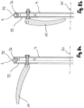
- Fig. 8a
- die Vergrößerung einer Betätigungsvorrichtung der vierten Verschlussvorrichtung, wobei sich das Verstellelement in der ersten Position befindet,
- Fig. 8b
- die Vergrößerung einer Betätigungsvorrichtung der vierten Verschlussvorrichtung, wobei sich das Verstellelement in der zweiten Position befindet.
- Sofern sinnvoll sind funktional gleichwirkende Teile mit identischen Bezugsziffern versehen.
-
Fig. 1 zeigt eine Verschlussvorrichtung 2 zum Verschließen eines Rohres in einer perspektivischen Darstellung. Die Verschlussvorrichtung 2 weist ein Trägerelement 4 und eine Dichtkontaktfläche 6 auf. Eine Verschlussvorrichtungsmittelachse 8 schneidet die Verschlussvorrichtung 2 in deren Mittelpunkt. Der Außenradius der Verschlussvorrichtung 2 ist entlang ihres Umfangs konstant. - Die Verschlussvorrichtung 2 hat ein Verstellelement 10, das unter anderem in den
Fig. 3c ,5b ,6b ,8a sowie 8b dargestellt ist. Dieses Verstellelement 10 ist relativ zum Trägerelement 4 aus einer ersten Position in eine zweite Position überführbar. In denFig. 2a ,5b und8a befindet sich das Verstellelement 10 der jeweils dargestellten Ausführungsform in seiner jeweiligen ersten Position. DieFig. 2a ,6b und8b zeigen die Verstellelemente 10 der gleichen Ausführungsbeispiele jeweils in ihrer zweiten Position. - In der zweiten Position des Verstellelementes 10 befindet sich die Verschlussvorrichtung 2 in seiner Dichtstellung. In der Dichtstellung liegt die Dichtkontaktfläche 6 bei Befinden der Verschlussvorrichtung 2 innerhalb eines Rohres mit korrespondierendem Durchmesser an dessen Rohrinnenfläche an und wirkt darauf mit einer Mindestflächenpressung. Außerhalb des Rohres zeichnet sich die Dichtstellung der Verschlussvorrichtung 2 dadurch aus, dass darin die Dichtkontaktfläche 6 der Verschlussvorrichtung 2 den maximalen Abstand von der Verschlussvorrichtungsmittelachse 8 hat.
- Das Verstellelement 10 ist relativ zum Trägerelement 4 um eine Betätigungsachse 12 schwenkbar (erste, zweite und vierte Ausführungsform) oder drehbar (dritte Ausführungsform). In den ersten beiden Ausführungsformen, welche durch die
Fig. 2a, 2b ,3b, 3c und4 dargestellt sind, umfasst die Betätigungsvorrichtung ein Exzenterelement 14, das um die Betätigungsachse 12 schwenkbar ist. Das Exzenterelement 14 hat eine von der Betätigungsachse 12 abgewandte Gleitoberfläche 16, die einen variierenden Abstand von der Betätigungsachse 12 hat. - Alternativ umfasst die Betätigungsvorrichtung ein Konuselement 18, welches in der dritten Ausführungsform gemäß den
Fig. 5a, 5b ,6a und 6b dargestellt ist. Das Konuselement 18 ist parallel zur Betätigungsachse 12 bewegbar. Auch das Konuselement 18 hat eine von der Betätigungsachse 12 abgewandte Gleitoberfläche 16, welche einen variierenden Abstand von der Betätigungsachse 12 hat. - Unter anderem die
Fig. 2a ,5b und8a zeigen ein Übertragungselement 22, welches durch die Überführung des Verstellelementes 10 von der ersten in die zweite Position translatorisch, parallel zu einer Übertragungsachse 20 verlagert wird. In der ersten, zweiten und dritten Ausführungsform liegt das Übertragungselement an der Gleitoberfläche an und wird durch dessen Rotation von der Betätigungsachse beabstandet. Die Übertragungsachse 20 ist in den Ausführungsformen gemäßFig. 2a und5b orthogonal zur Verschlussvorrichtungsmittelachse 8 angeordnet. Davon abweichend ist sie beim vierten Ausführungsbeispiel gemäß denFig. 7 ,8a und 8b parallel zur Verschlussvorrichtungsmittelachse 8 angeordnet. - Die
Fig. 2a, 2b und4 zeigen eine Führungsanordnung 24, durch welche das Übertragungselement 22 relativ zum Trägerelement 4 parallel zur Übertragungsachse 20 geführt wird. Die Führungsanordnung umfasst zum einen ein Langloch im Übertragungselement und zum anderen einen Führungsstift des Trägerelementes. Während die Ausführungsform der erfindungsgemäßen Verschlussvorrichtung 2 gemäß denFig. 2a und 2b vier Übertragungselemente 22 aufweist, weist die Ausführungsform gemäßFig. 8a und 8b ein Übertragungselement 22 auf. Die vier Übertragungselemente 22 der ersten genannten Ausführungsform haben jeweils eine von der Verschlussvorrichtungsmittelachse 8 abgewandte Pressfläche 26, welche in der Dichtstellung des Verschlusselementes 10 in einer gedachten Kreiszylindermantelfläche angeordnet sind, deren Symmetrieachse mit der Verschlussvorrichtungsmittelachse 8 zusammenfällt. Die Pressflächen 26 verlaufen dabei vollumfänglich um die Verschlussvorrichtungsmittelachse 8 bzw. die Verschlussvorrichtung 2 an sich. Die Pressfläche vom Übertragungselement in denFig. 7 und8 ist dagegen senkrecht zur Verschlussvorrichtungsmittelachse angeordnet und das eine Übertragungselement axial verschieblich. - In den
Figuren 1 bis 6b nicht dargestellt ist, dass sich bei Befinden der Verstellelemente 10 der ersten, zweiten und dritten Ausführungsform der Verschlussvorrichtung in ihrer ersten Position die jeweils benachbarten Übertragungselemente 22 sich mit je einem Seitenabschnitt 28 in axialer Richtung überlagern. Zwischen zwei Seitenabschnitten 28 liegt ein Mittelabschnitt 30. Die in Richtung der Verschlussvorrichtungsmittelachse 8 gemessene Stärke der Seitenabschnitte 28 ist um die Hälfte der Stärke des Mittelabschnittes 30 geringer als dessen Stärke. Somit können die aneinander angrenzenden Seitenabschnitte bei Verringerung des Pressflächenradius ineinander eingreifen. - In allen dargestellten Ausführungsformen weist die Verschlussvorrichtung 2 ein Dichtelement 32 auf (vergl. insbesondere
Fig. 3c undFig. 8a ). Das Dichtelement 32 ist eine um die Verschlussvorrichtungsmittelachse 8 umlaufende Ringdichtung und hat bei der Ausführungsform gemäßFig. 3c als Kreuzdichtung zwei Dichtkontaktflächen. Die in der durchFig. 8a und 8b dargestellten Ausführungsformen gezeigte Ringdichtung hat dagegen einen runden Querschnitt und nur eine Dichtkontaktfläche 6. Unabhängig von der Form des Dichtelementes 32 liegt dieses an dem Übertragungselement 22 (vergl. z. B.Fig. 8a ) bzw. den Übertragungselementen 22 (vergl. z. B.Fig. 2a oder5b ) an. In jeder dargestellten Ausführungsform weist die Verschlussvorrichtung 2 eine am Trägerelement 4 angeordnete gasdurchlässige Membran 34 auf, die zur Ermöglichung des Durchtritts von Gas durch die Verschlussvorrichtung 2 dient. -
Fig. 4 zeigt auf dem Verstellelement 10 einen optischen Indikator 36. Dieser ist ein eingefärbter Bereich der Oberfläche des Verstellelementes 10, welcher bei der Überführung des Verstellelementes von der ersten in die zweite Position bewegt wird. Durch die Bewegung wird der eingefärbte Bereich aus einer Stellung, in der er durch das Trägerelement verdeckt wird, in eine Stellung überführt, in der er Deckungsgleich mit einer vom optischen Indikator 36 umfassten Ausnehmung im Trägerelement 4 ist. InFig. 1 sind diese Ausnehmungen auf einer Hälfte des Trägerelementes 4 dargestellt. Durch diesen optischen Indikator 36 wird somit die Stellung des Verstellelementes nach außen kenntlich gemacht.
Claims (15)
- Verschlussvorrichtung (2) zum Verschließen eines Rohres, mit einem Trägerelement (4), zumindest einer Dichtkontaktfläche (6), einer Verschlussvorrichtungsmittelachse (8) und zumindest einer Betätigungsvorrichtung mit mindestens einem Verstellelement (10), das relativ zum Trägerelement (4) aus einer ersten Position in eine zweite Position überführbar ist, wobei in der zweiten Position des Verstellelementes (10) die Verschlussvorrichtung (2) sich in einer Dichtstellung befindet, wobei das Verstellelement (10) relativ zum Trägerelement (4) um eine zur Verschlussvorrichtungsmittelachse (8) im Wesentlichen parallele Betätigungsachse (12) schwenkbar oder drehbar ist, wobei die Betätigungsvorrichtung ein Exzenterelement (14) umfasst, das um die Betätigungsachse (12) schwenkbar ist, wovon eine von der Betätigungsachse (12) abgewandte Gleitoberfläche (16) einen variierenden Abstand von der Betätigungsachse (12) hat und das zur Übersetzung einer Rotationsbewegung um die Betätigungsachse (8) in eine translatorische Bewegung ausgebildet ist, wodurch die gewünschte Flächenpressung der Dichtkontaktfläche (6), welche in der Dichtstellung nötig ist, durch eine Kraft in radialer Richtung hergestellt wird, wobei die Verschlussvorrichtung (2) zumindest ein durch die Überführung des Verstellelementes (10) von der ersten in die zweite Position translatorisch, parallel zu einer Übertragungsachse (20) verlagertes Übertragungselement (22) aufweist.
- Verschlussvorrichtung nach Anspruch 1, dadurch gekennzeichnet, dass die Übertragungsachse (20) relativ zur Verschlussvorrichtungsmittelachse (8) um 80° bis 100° verkippt angeordnet.
- Verschlussvorrichtung nach einem der vorhergehenden Ansprüche, dadurch gekennzeichnet, dass das Übertragungselement (22) an der Gleitoberfläche (16) anliegend angeordnet ist, wobei das Übertragungselement (22) durch die Bewegung der Gleitoberfläche (16) verlagert wird.
- Verschlussvorrichtung nach einem der vorhergehenden Ansprüche, dadurch gekennzeichnet, dass zwischen dem Trägerelement (4) und dem Übertragungselement (22) zumindest eine die Bewegung des Übertragungselementes (22) parallel zur Übertragungsachse (20) führende Führungsanordnung (24) angeordnet ist
- Verschlussvorrichtung nach einem der vorhergehenden Ansprüche, gekennzeichnet durch mindestens drei Übertragungselemente (22) mit jeweils zumindest einer von der Verschlussvorrichtungsmittelachse (8) abgewandten Pressfläche (26), welche in der Dichtstellung des Verschlusselementes (2) von einer gedachten Kreiszylindermantelfläche, deren Symmetrieachse mit der Verschlussvorrichtungsmittelachse (8) zusammenfällt, um höchstens ein Fünftel des Radius der Kreiszylindermantelfläche abweicht.
- Verschlussvorrichtung nach Anspruch 5, dadurch gekennzeichnet, dass die Pressflächen (26) der Übertragungselemente (22) bei Betrachtung in Richtung der Verschlussvorrichtungsmittelachse (8) zur in Umfangsrichtung bündigen Anlage an die Rohrinnenfläche im Wesentlichen vollumfänglich um die Verschlussvorrichtungsmittelachse (8) verlaufend angeordnet sind.
- Verschlussvorrichtung nach Anspruch 5 oder 6, dadurch gekennzeichnet, dass sich zumindest bei Befinden des Verstellelementes (10) in der ersten Position zwei benachbarte Übertragungselemente (22) bei deren Betrachtung in Richtung der Verschlussvorrichtungsmittelachse (8) mit je einem Seitenabschnitt (28) überlagern.
- Verschlussvorrichtung nach Anspruch 7, dadurch gekennzeichnet, dass die Übertragungselemente (22) zwei an einen Mittelabschnitt (30) angrenzende Seitenabschnitte (28) aufweisen, wobei die in Richtung der Verschlussvorrichtungsmittelachse (8) gemessene Stärke der Seitenabschnitte (28) um zumindest ein Drittel, insbesondere um die Hälfte der Stärke des Mittelabschnittes (30) geringer ist als dessen Stärke.
- Verschlussvorrichtung nach einem der vorhergehenden Ansprüche, gekennzeichnet durch mindestens ein Dichtelement (32), das die Dichtkontaktfläche (6) aufweist.
- Verschlussvorrichtung nach Anspruch 9, dadurch gekennzeichnet, dass die Verschlussvorrichtung (2) genau ein Dichtelement (32) aufweist, welches als um die Verschlussvorrichtungsmittelachse (8) umlaufende Ringdichtung ausgebildet ist und die zumindest eine Dichtkontaktfläche (6) aufweist.
- Verschlussvorrichtung nach Anspruch 9 oder 10, dadurch gekennzeichnet, dass das Dichtelement (32) in der Dichtstellung zumindest teilweise am Übertragungselement (22) anliegend angeordnet ist.
- Verschlussvorrichtung nach einem der vorhergehenden Ansprüche, dadurch gekennzeichnet, dass das Trägerelement (4) überwiegend aus einem Polypropylen-Glasfaser-Composit besteht.
- Verschlussvorrichtung nach einem der vorhergehenden Ansprüche, gekennzeichnet durch einen die Stellung des Verstellelementes (10) anzeigenden optischen Indikator (36).
- Verschlussvorrichtung nach einem der vorhergehenden Ansprüche, dadurch gekennzeichnet, dass am Trägerelement (4) eine gasdurchlässige Membran (34) zur Ermöglichung des Durchtritts von Gas durch die Verschlussvorrichtung (2) angeordnet ist.
- Verschlussvorrichtung nach einem der vorhergehenden Ansprüche, gekennzeichnet durch am Trägerelement (4) angeordnete Handgriffe.
Applications Claiming Priority (2)
| Application Number | Priority Date | Filing Date | Title |
|---|---|---|---|
| DE202017104929.9U DE202017104929U1 (de) | 2017-08-16 | 2017-08-16 | Verschlussvorrichtung |
| PCT/EP2018/068281 WO2019034327A1 (de) | 2017-08-16 | 2018-07-05 | Verschlussvorrichtung |
Publications (4)
| Publication Number | Publication Date |
|---|---|
| EP3669111A1 EP3669111A1 (de) | 2020-06-24 |
| EP3669111C0 EP3669111C0 (de) | 2023-11-15 |
| EP3669111B1 true EP3669111B1 (de) | 2023-11-15 |
| EP3669111B8 EP3669111B8 (de) | 2023-12-20 |
Family
ID=62976020
Family Applications (1)
| Application Number | Title | Priority Date | Filing Date |
|---|---|---|---|
| EP18742949.3A Active EP3669111B8 (de) | 2017-08-16 | 2018-07-05 | Verschlussvorrichtung |
Country Status (8)
| Country | Link |
|---|---|
| US (1) | US12013073B2 (de) |
| EP (1) | EP3669111B8 (de) |
| CN (1) | CN111226071B (de) |
| AU (1) | AU2018319055B2 (de) |
| CA (1) | CA3073124A1 (de) |
| DE (1) | DE202017104929U1 (de) |
| MY (1) | MY204261A (de) |
| WO (1) | WO2019034327A1 (de) |
Families Citing this family (2)
| Publication number | Priority date | Publication date | Assignee | Title |
|---|---|---|---|---|
| NL2025662B1 (en) * | 2020-05-25 | 2021-12-13 | Dhatec B V | Plug for a pipe and method for closing off a pipe |
| CN118837384B (zh) * | 2024-09-19 | 2024-12-27 | 洛阳睿信工程设计有限公司 | 一种水利工程用管道质量检测装置 |
Family Cites Families (34)
| Publication number | Priority date | Publication date | Assignee | Title |
|---|---|---|---|---|
| US278670A (en) * | 1883-05-29 | Expansible barrel-cover | ||
| US1216972A (en) * | 1915-06-18 | 1917-02-20 | Hartley Ellis | Barrel-head. |
| US1375645A (en) * | 1919-09-02 | 1921-04-19 | Clarence F Unckrich | Door-lock for open-end vaults |
| US2181905A (en) * | 1936-11-18 | 1939-12-05 | Fibresteel Inc | Container and method of making the same |
| US2797018A (en) * | 1954-09-24 | 1957-06-25 | Lummus Co | Pressure head seal |
| US3184099A (en) * | 1963-06-17 | 1965-05-18 | Marine Moisture Control Co | Closure plate for cargo tanker |
| US3543801A (en) * | 1968-05-24 | 1970-12-01 | Floyd L Thayer | Closure means for conduits and the like |
| US3606070A (en) * | 1969-10-06 | 1971-09-20 | Shepherd Machinery Co | Lockable tank closure with expandable plug |
| US3861550A (en) * | 1973-05-21 | 1975-01-21 | Allied Chem | Liquid container with perforatable locking closure |
| US4288001A (en) * | 1980-07-15 | 1981-09-08 | Gulf & Western Manufacturing Company | Closure arrangement for pressure device |
| GB2110653A (en) * | 1981-12-02 | 1983-06-22 | British Gas Corp | Expansible plug |
| GB2134206B (en) * | 1983-01-24 | 1986-02-12 | Swinney Eng | Closure for pipes or vessels |
| DE3523504A1 (de) * | 1985-07-01 | 1987-01-08 | Thyssen Plastik Anger Kg | Abdichtstopfen |
| GB8809516D0 (en) * | 1988-04-22 | 1988-05-25 | Plenty Ltd | Improved closure for pipe/vessel |
| DE4213732C2 (de) * | 1992-04-25 | 2000-01-27 | Bosch Gmbh Robert | Verschlußstück zum Abschließen von Druckmittel führenden Bohrungen |
| FR2769351B1 (fr) * | 1997-10-02 | 1999-11-05 | So Co Di Societe Commerciale D | Dispositif destine a obturer une canalisation de vidange |
| EP1229173A1 (de) * | 2001-02-06 | 2002-08-07 | Karl Kortmann | Verschlussvorrichtung für Rohrleitungen, insbesondere Schachtrohre |
| TW509050U (en) * | 2001-07-02 | 2002-11-01 | Avision Inc | Plug structure for liquid discharge device |
| DE20116201U1 (de) * | 2001-10-02 | 2002-02-21 | F.W. Oventrop GmbH & Co. KG, 59939 Olsberg | Wiederverwendbarer Rohrverschluss |
| CN2886286Y (zh) * | 2006-04-25 | 2007-04-04 | 沙垣 | 地下管道的修补装置 |
| US7644734B2 (en) * | 2007-03-15 | 2010-01-12 | Safety Pumping Systems, Llc | Safety cap for couplings and fittings |
| US8109407B2 (en) * | 2007-05-30 | 2012-02-07 | Taiwan Semiconductor Manufacturing Co., Ltd. | Apparatus for storing substrates |
| US8001988B2 (en) | 2008-06-09 | 2011-08-23 | Tdw Delaware, Inc. | Verifiable closing and locking system of a cylindrical passageway |
| NL2001969C2 (en) * | 2008-09-03 | 2010-03-12 | Blg Machineverhuur | Wellbore pipe protection device. |
| JP5466166B2 (ja) * | 2008-11-06 | 2014-04-09 | 日本ゴア株式会社 | 通気栓 |
| DE202009018746U1 (de) * | 2008-12-23 | 2013-02-01 | Rosen Swiss Ag | Abdeckvorrichtung für ein Rohr und Rohr mit einer solchen Abdeckvorrichtung |
| US8141591B2 (en) * | 2009-08-17 | 2012-03-27 | Alstom Technology Ltd | Plug assembly with moveable mounting members |
| DE102010050720A1 (de) * | 2010-11-08 | 2012-05-10 | De Dietrich Process Systems Gmbh | Rohrleitung, Dichtelement und Rohrverbindung |
| KR20130057917A (ko) * | 2011-11-24 | 2013-06-03 | 황윤하 | 맨홀뚜껑의 잠금장치 |
| DE102012023174A1 (de) * | 2012-11-28 | 2014-06-12 | Rosen Swiss Ag | Abdeckvorrichtung |
| CN103883837B (zh) * | 2014-03-28 | 2016-01-13 | 北京乾坤润林科技开发有限公司 | 可调节内外尺寸的管道封堵件 |
| DE202015002284U1 (de) * | 2015-03-25 | 2015-04-20 | Abdullah Cobankara | Mechanisches Rohrverschlusswiderlager |
| CN204805532U (zh) * | 2015-05-27 | 2015-11-25 | 江阴市巨匠文化创意发展有限公司 | 一种管体端部密封组件 |
| CN205842090U (zh) * | 2016-07-21 | 2016-12-28 | 厦门爱陶卫浴有限公司 | 一种管道堵头 |
-
2017
- 2017-08-16 DE DE202017104929.9U patent/DE202017104929U1/de not_active Expired - Lifetime
-
2018
- 2018-07-05 AU AU2018319055A patent/AU2018319055B2/en active Active
- 2018-07-05 MY MYPI2020000836A patent/MY204261A/en unknown
- 2018-07-05 WO PCT/EP2018/068281 patent/WO2019034327A1/de not_active Ceased
- 2018-07-05 CA CA3073124A patent/CA3073124A1/en active Pending
- 2018-07-05 US US16/639,671 patent/US12013073B2/en active Active
- 2018-07-05 EP EP18742949.3A patent/EP3669111B8/de active Active
- 2018-07-05 CN CN201880067327.7A patent/CN111226071B/zh active Active
Also Published As
| Publication number | Publication date |
|---|---|
| EP3669111B8 (de) | 2023-12-20 |
| AU2018319055B2 (en) | 2024-02-08 |
| CA3073124A1 (en) | 2019-02-21 |
| DE202017104929U1 (de) | 2018-11-19 |
| US20200248859A1 (en) | 2020-08-06 |
| MY204261A (en) | 2024-08-19 |
| AU2018319055A1 (en) | 2020-03-05 |
| US12013073B2 (en) | 2024-06-18 |
| EP3669111C0 (de) | 2023-11-15 |
| WO2019034327A1 (de) | 2019-02-21 |
| EP3669111A1 (de) | 2020-06-24 |
| CN111226071B (zh) | 2022-03-22 |
| RU2020110071A3 (de) | 2021-12-28 |
| CN111226071A (zh) | 2020-06-02 |
| RU2020110071A (ru) | 2021-09-16 |
Similar Documents
| Publication | Publication Date | Title |
|---|---|---|
| EP3149354B1 (de) | Teleskopierbare federstütze | |
| DE19729876C2 (de) | Steckverbinder für Koaxialkabel | |
| DE2736050C2 (de) | Dichtung für einen Schraubentrieb | |
| DE2058203C2 (de) | Rohrverbinder | |
| DE69911362T2 (de) | Anordnung zum Verbinden zweier rohrförmiger Elemente | |
| DE2304661A1 (de) | Reibungskupplung bzw. -verbindung | |
| DE102016110601B4 (de) | Druckdämpfungsvorrichtung und elastisches Glied | |
| DE2923902A1 (de) | Kupplung | |
| DE69113967T2 (de) | Drehantrieb mit Ringkolbenstange. | |
| DE102012209629B4 (de) | Aufnahmeteil einer Trockenkupplung | |
| EP3669111B1 (de) | Verschlussvorrichtung | |
| EP3649712B1 (de) | Kabeldurchführungseinrichtung | |
| DE3590297T (de) | Schlagend arbeitende Druckluft-Reversiervorrichtung | |
| EP4067716B1 (de) | Rohrabschnittsmontagevorrichtung | |
| EP0622574A2 (de) | Betätigungsvorrichtung für ein drehbares Verschlussstück eines Ventils | |
| DE102020113979B4 (de) | Verschlussmechanismus | |
| DE2342069B2 (de) | Kugelhahn mit frei beweglichen dichtungssitzringen | |
| DE102010048776A1 (de) | Schraubenhalterung | |
| DE102010027444B3 (de) | Kabelzugentlastung und Dichtungssystem | |
| DE3024451C2 (de) | Schaltraste für Fahrzeugschaltgetriebe | |
| DE2915889C2 (de) | Klappenventil | |
| EP4078002B1 (de) | Schnellkupplung zum verbinden | |
| EP3631258A1 (de) | Membrangedichtetes doppelsitzventil und antrieb | |
| DE3925888C2 (de) | ||
| DE202007003822U1 (de) | Friktionsbremse und Stativ mit einer derartigen Bremse |
Legal Events
| Date | Code | Title | Description |
|---|---|---|---|
| STAA | Information on the status of an ep patent application or granted ep patent |
Free format text: STATUS: UNKNOWN |
|
| STAA | Information on the status of an ep patent application or granted ep patent |
Free format text: STATUS: THE INTERNATIONAL PUBLICATION HAS BEEN MADE |
|
| PUAI | Public reference made under article 153(3) epc to a published international application that has entered the european phase |
Free format text: ORIGINAL CODE: 0009012 |
|
| STAA | Information on the status of an ep patent application or granted ep patent |
Free format text: STATUS: REQUEST FOR EXAMINATION WAS MADE |
|
| 17P | Request for examination filed |
Effective date: 20200310 |
|
| AK | Designated contracting states |
Kind code of ref document: A1 Designated state(s): AL AT BE BG CH CY CZ DE DK EE ES FI FR GB GR HR HU IE IS IT LI LT LU LV MC MK MT NL NO PL PT RO RS SE SI SK SM TR |
|
| AX | Request for extension of the european patent |
Extension state: BA ME |
|
| DAV | Request for validation of the european patent (deleted) | ||
| DAX | Request for extension of the european patent (deleted) | ||
| STAA | Information on the status of an ep patent application or granted ep patent |
Free format text: STATUS: EXAMINATION IS IN PROGRESS |
|
| 17Q | First examination report despatched |
Effective date: 20220224 |
|
| GRAP | Despatch of communication of intention to grant a patent |
Free format text: ORIGINAL CODE: EPIDOSNIGR1 |
|
| STAA | Information on the status of an ep patent application or granted ep patent |
Free format text: STATUS: GRANT OF PATENT IS INTENDED |
|
| GRAS | Grant fee paid |
Free format text: ORIGINAL CODE: EPIDOSNIGR3 |
|
| INTG | Intention to grant announced |
Effective date: 20230215 |
|
| GRAJ | Information related to disapproval of communication of intention to grant by the applicant or resumption of examination proceedings by the epo deleted |
Free format text: ORIGINAL CODE: EPIDOSDIGR1 |
|
| GRAL | Information related to payment of fee for publishing/printing deleted |
Free format text: ORIGINAL CODE: EPIDOSDIGR3 |
|
| STAA | Information on the status of an ep patent application or granted ep patent |
Free format text: STATUS: EXAMINATION IS IN PROGRESS |
|
| GRAP | Despatch of communication of intention to grant a patent |
Free format text: ORIGINAL CODE: EPIDOSNIGR1 |
|
| STAA | Information on the status of an ep patent application or granted ep patent |
Free format text: STATUS: GRANT OF PATENT IS INTENDED |
|
| INTC | Intention to grant announced (deleted) | ||
| INTG | Intention to grant announced |
Effective date: 20230630 |
|
| GRAS | Grant fee paid |
Free format text: ORIGINAL CODE: EPIDOSNIGR3 |
|
| GRAA | (expected) grant |
Free format text: ORIGINAL CODE: 0009210 |
|
| STAA | Information on the status of an ep patent application or granted ep patent |
Free format text: STATUS: THE PATENT HAS BEEN GRANTED |
|
| AK | Designated contracting states |
Kind code of ref document: B1 Designated state(s): AL AT BE BG CH CY CZ DE DK EE ES FI FR GB GR HR HU IE IS IT LI LT LU LV MC MK MT NL NO PL PT RO RS SE SI SK SM TR |
|
| REG | Reference to a national code |
Ref country code: CH Ref legal event code: EP Ref country code: GB Ref legal event code: FG4D Free format text: NOT ENGLISH |
|
| REG | Reference to a national code |
Ref country code: DE Ref legal event code: R081 Ref document number: 502018013633 Country of ref document: DE Owner name: ROSEN IP AG, CH Free format text: FORMER OWNER: ROSEN SWISS AG, STANS, CH |
|
| REG | Reference to a national code |
Ref country code: CH Ref legal event code: PK Free format text: BERICHTIGUNG B8 Ref country code: DE Ref legal event code: R096 Ref document number: 502018013633 Country of ref document: DE |
|
| REG | Reference to a national code |
Ref country code: IE Ref legal event code: FG4D Free format text: LANGUAGE OF EP DOCUMENT: GERMAN |
|
| RAP2 | Party data changed (patent owner data changed or rights of a patent transferred) |
Owner name: ROSEN IP AG |
|
| U01 | Request for unitary effect filed |
Effective date: 20231215 |
|
| U07 | Unitary effect registered |
Designated state(s): AT BE BG DE DK EE FI FR IT LT LU LV MT NL PT SE SI Effective date: 20231221 |
|
| PG25 | Lapsed in a contracting state [announced via postgrant information from national office to epo] |
Ref country code: GR Free format text: LAPSE BECAUSE OF FAILURE TO SUBMIT A TRANSLATION OF THE DESCRIPTION OR TO PAY THE FEE WITHIN THE PRESCRIBED TIME-LIMIT Effective date: 20240216 |
|
| PG25 | Lapsed in a contracting state [announced via postgrant information from national office to epo] |
Ref country code: IS Free format text: LAPSE BECAUSE OF FAILURE TO SUBMIT A TRANSLATION OF THE DESCRIPTION OR TO PAY THE FEE WITHIN THE PRESCRIBED TIME-LIMIT Effective date: 20240315 |
|
| PG25 | Lapsed in a contracting state [announced via postgrant information from national office to epo] |
Ref country code: ES Free format text: LAPSE BECAUSE OF FAILURE TO SUBMIT A TRANSLATION OF THE DESCRIPTION OR TO PAY THE FEE WITHIN THE PRESCRIBED TIME-LIMIT Effective date: 20231115 |
|
| PG25 | Lapsed in a contracting state [announced via postgrant information from national office to epo] |
Ref country code: IS Free format text: LAPSE BECAUSE OF FAILURE TO SUBMIT A TRANSLATION OF THE DESCRIPTION OR TO PAY THE FEE WITHIN THE PRESCRIBED TIME-LIMIT Effective date: 20240315 Ref country code: GR Free format text: LAPSE BECAUSE OF FAILURE TO SUBMIT A TRANSLATION OF THE DESCRIPTION OR TO PAY THE FEE WITHIN THE PRESCRIBED TIME-LIMIT Effective date: 20240216 Ref country code: ES Free format text: LAPSE BECAUSE OF FAILURE TO SUBMIT A TRANSLATION OF THE DESCRIPTION OR TO PAY THE FEE WITHIN THE PRESCRIBED TIME-LIMIT Effective date: 20231115 |
|
| PG25 | Lapsed in a contracting state [announced via postgrant information from national office to epo] |
Ref country code: RS Free format text: LAPSE BECAUSE OF FAILURE TO SUBMIT A TRANSLATION OF THE DESCRIPTION OR TO PAY THE FEE WITHIN THE PRESCRIBED TIME-LIMIT Effective date: 20231115 Ref country code: PL Free format text: LAPSE BECAUSE OF FAILURE TO SUBMIT A TRANSLATION OF THE DESCRIPTION OR TO PAY THE FEE WITHIN THE PRESCRIBED TIME-LIMIT Effective date: 20231115 Ref country code: NO Free format text: LAPSE BECAUSE OF FAILURE TO SUBMIT A TRANSLATION OF THE DESCRIPTION OR TO PAY THE FEE WITHIN THE PRESCRIBED TIME-LIMIT Effective date: 20240215 Ref country code: HR Free format text: LAPSE BECAUSE OF FAILURE TO SUBMIT A TRANSLATION OF THE DESCRIPTION OR TO PAY THE FEE WITHIN THE PRESCRIBED TIME-LIMIT Effective date: 20231115 |
|
| PG25 | Lapsed in a contracting state [announced via postgrant information from national office to epo] |
Ref country code: CZ Free format text: LAPSE BECAUSE OF FAILURE TO SUBMIT A TRANSLATION OF THE DESCRIPTION OR TO PAY THE FEE WITHIN THE PRESCRIBED TIME-LIMIT Effective date: 20231115 |
|
| PG25 | Lapsed in a contracting state [announced via postgrant information from national office to epo] |
Ref country code: SK Free format text: LAPSE BECAUSE OF FAILURE TO SUBMIT A TRANSLATION OF THE DESCRIPTION OR TO PAY THE FEE WITHIN THE PRESCRIBED TIME-LIMIT Effective date: 20231115 |
|
| PG25 | Lapsed in a contracting state [announced via postgrant information from national office to epo] |
Ref country code: SM Free format text: LAPSE BECAUSE OF FAILURE TO SUBMIT A TRANSLATION OF THE DESCRIPTION OR TO PAY THE FEE WITHIN THE PRESCRIBED TIME-LIMIT Effective date: 20231115 Ref country code: SK Free format text: LAPSE BECAUSE OF FAILURE TO SUBMIT A TRANSLATION OF THE DESCRIPTION OR TO PAY THE FEE WITHIN THE PRESCRIBED TIME-LIMIT Effective date: 20231115 Ref country code: RO Free format text: LAPSE BECAUSE OF FAILURE TO SUBMIT A TRANSLATION OF THE DESCRIPTION OR TO PAY THE FEE WITHIN THE PRESCRIBED TIME-LIMIT Effective date: 20231115 Ref country code: CZ Free format text: LAPSE BECAUSE OF FAILURE TO SUBMIT A TRANSLATION OF THE DESCRIPTION OR TO PAY THE FEE WITHIN THE PRESCRIBED TIME-LIMIT Effective date: 20231115 |
|
| REG | Reference to a national code |
Ref country code: DE Ref legal event code: R097 Ref document number: 502018013633 Country of ref document: DE |
|
| U20 | Renewal fee for the european patent with unitary effect paid |
Year of fee payment: 7 Effective date: 20240717 |
|
| PLBE | No opposition filed within time limit |
Free format text: ORIGINAL CODE: 0009261 |
|
| STAA | Information on the status of an ep patent application or granted ep patent |
Free format text: STATUS: NO OPPOSITION FILED WITHIN TIME LIMIT |
|
| 26N | No opposition filed |
Effective date: 20240819 |
|
| PG25 | Lapsed in a contracting state [announced via postgrant information from national office to epo] |
Ref country code: MC Free format text: LAPSE BECAUSE OF FAILURE TO SUBMIT A TRANSLATION OF THE DESCRIPTION OR TO PAY THE FEE WITHIN THE PRESCRIBED TIME-LIMIT Effective date: 20231115 |
|
| REG | Reference to a national code |
Ref country code: CH Ref legal event code: PL |
|
| PG25 | Lapsed in a contracting state [announced via postgrant information from national office to epo] |
Ref country code: CH Free format text: LAPSE BECAUSE OF NON-PAYMENT OF DUE FEES Effective date: 20240731 |
|
| PG25 | Lapsed in a contracting state [announced via postgrant information from national office to epo] |
Ref country code: IE Free format text: LAPSE BECAUSE OF NON-PAYMENT OF DUE FEES Effective date: 20240705 |
|
| U20 | Renewal fee for the european patent with unitary effect paid |
Year of fee payment: 8 Effective date: 20250729 |
|
| PGFP | Annual fee paid to national office [announced via postgrant information from national office to epo] |
Ref country code: GB Payment date: 20250724 Year of fee payment: 8 |
|
| PG25 | Lapsed in a contracting state [announced via postgrant information from national office to epo] |
Ref country code: CY Free format text: LAPSE BECAUSE OF FAILURE TO SUBMIT A TRANSLATION OF THE DESCRIPTION OR TO PAY THE FEE WITHIN THE PRESCRIBED TIME-LIMIT; INVALID AB INITIO Effective date: 20180705 |
|
| PG25 | Lapsed in a contracting state [announced via postgrant information from national office to epo] |
Ref country code: HU Free format text: LAPSE BECAUSE OF FAILURE TO SUBMIT A TRANSLATION OF THE DESCRIPTION OR TO PAY THE FEE WITHIN THE PRESCRIBED TIME-LIMIT; INVALID AB INITIO Effective date: 20180705 |