EP3669451B1 - Procede pour un entraînement multimoteur - Google Patents
Procede pour un entraînement multimoteur Download PDFInfo
- Publication number
- EP3669451B1 EP3669451B1 EP18793428.6A EP18793428A EP3669451B1 EP 3669451 B1 EP3669451 B1 EP 3669451B1 EP 18793428 A EP18793428 A EP 18793428A EP 3669451 B1 EP3669451 B1 EP 3669451B1
- Authority
- EP
- European Patent Office
- Prior art keywords
- motor
- motors
- control
- converter
- option
- Prior art date
- Legal status (The legal status is an assumption and is not a legal conclusion. Google has not performed a legal analysis and makes no representation as to the accuracy of the status listed.)
- Active
Links
Images
Classifications
-
- H—ELECTRICITY
- H02—GENERATION; CONVERSION OR DISTRIBUTION OF ELECTRIC POWER
- H02P—CONTROL OR REGULATION OF ELECTRIC MOTORS, ELECTRIC GENERATORS OR DYNAMO-ELECTRIC CONVERTERS; CONTROLLING TRANSFORMERS, REACTORS OR CHOKE COILS
- H02P5/00—Arrangements specially adapted for regulating or controlling the speed or torque of two or more electric motors
- H02P5/46—Arrangements specially adapted for regulating or controlling the speed or torque of two or more electric motors for speed regulation of two or more dynamo-electric motors in relation to one another
-
- H—ELECTRICITY
- H02—GENERATION; CONVERSION OR DISTRIBUTION OF ELECTRIC POWER
- H02P—CONTROL OR REGULATION OF ELECTRIC MOTORS, ELECTRIC GENERATORS OR DYNAMO-ELECTRIC CONVERTERS; CONTROLLING TRANSFORMERS, REACTORS OR CHOKE COILS
- H02P5/00—Arrangements specially adapted for regulating or controlling the speed or torque of two or more electric motors
-
- H—ELECTRICITY
- H02—GENERATION; CONVERSION OR DISTRIBUTION OF ELECTRIC POWER
- H02P—CONTROL OR REGULATION OF ELECTRIC MOTORS, ELECTRIC GENERATORS OR DYNAMO-ELECTRIC CONVERTERS; CONTROLLING TRANSFORMERS, REACTORS OR CHOKE COILS
- H02P21/00—Arrangements or methods for the control of electric machines by vector control, e.g. by control of field orientation
- H02P21/12—Stator flux based control involving the use of rotor position or rotor speed sensors
-
- H—ELECTRICITY
- H02—GENERATION; CONVERSION OR DISTRIBUTION OF ELECTRIC POWER
- H02P—CONTROL OR REGULATION OF ELECTRIC MOTORS, ELECTRIC GENERATORS OR DYNAMO-ELECTRIC CONVERTERS; CONTROLLING TRANSFORMERS, REACTORS OR CHOKE COILS
- H02P21/00—Arrangements or methods for the control of electric machines by vector control, e.g. by control of field orientation
- H02P21/14—Estimation or adaptation of machine parameters, e.g. flux, current or voltage
- H02P21/18—Estimation of position or speed
-
- H—ELECTRICITY
- H02—GENERATION; CONVERSION OR DISTRIBUTION OF ELECTRIC POWER
- H02P—CONTROL OR REGULATION OF ELECTRIC MOTORS, ELECTRIC GENERATORS OR DYNAMO-ELECTRIC CONVERTERS; CONTROLLING TRANSFORMERS, REACTORS OR CHOKE COILS
- H02P21/00—Arrangements or methods for the control of electric machines by vector control, e.g. by control of field orientation
- H02P21/22—Current control, e.g. using a current control loop
-
- H—ELECTRICITY
- H02—GENERATION; CONVERSION OR DISTRIBUTION OF ELECTRIC POWER
- H02P—CONTROL OR REGULATION OF ELECTRIC MOTORS, ELECTRIC GENERATORS OR DYNAMO-ELECTRIC CONVERTERS; CONTROLLING TRANSFORMERS, REACTORS OR CHOKE COILS
- H02P27/00—Arrangements or methods for the control of AC motors characterised by the kind of supply voltage
- H02P27/04—Arrangements or methods for the control of AC motors characterised by the kind of supply voltage using variable-frequency supply voltage, e.g. inverter or converter supply voltage
- H02P27/06—Arrangements or methods for the control of AC motors characterised by the kind of supply voltage using variable-frequency supply voltage, e.g. inverter or converter supply voltage using DC to AC converters or inverters
-
- H—ELECTRICITY
- H02—GENERATION; CONVERSION OR DISTRIBUTION OF ELECTRIC POWER
- H02P—CONTROL OR REGULATION OF ELECTRIC MOTORS, ELECTRIC GENERATORS OR DYNAMO-ELECTRIC CONVERTERS; CONTROLLING TRANSFORMERS, REACTORS OR CHOKE COILS
- H02P5/00—Arrangements specially adapted for regulating or controlling the speed or torque of two or more electric motors
- H02P5/74—Arrangements specially adapted for regulating or controlling the speed or torque of two or more electric motors controlling two or more AC dynamo-electric motors
-
- H—ELECTRICITY
- H02—GENERATION; CONVERSION OR DISTRIBUTION OF ELECTRIC POWER
- H02P—CONTROL OR REGULATION OF ELECTRIC MOTORS, ELECTRIC GENERATORS OR DYNAMO-ELECTRIC CONVERTERS; CONTROLLING TRANSFORMERS, REACTORS OR CHOKE COILS
- H02P6/00—Arrangements for controlling synchronous motors or other dynamo-electric motors using electronic commutation dependent on the rotor position; Electronic commutators therefor
- H02P6/04—Arrangements for controlling or regulating the speed or torque of more than one motor
-
- H—ELECTRICITY
- H02—GENERATION; CONVERSION OR DISTRIBUTION OF ELECTRIC POWER
- H02P—CONTROL OR REGULATION OF ELECTRIC MOTORS, ELECTRIC GENERATORS OR DYNAMO-ELECTRIC CONVERTERS; CONTROLLING TRANSFORMERS, REACTORS OR CHOKE COILS
- H02P6/00—Arrangements for controlling synchronous motors or other dynamo-electric motors using electronic commutation dependent on the rotor position; Electronic commutators therefor
- H02P6/04—Arrangements for controlling or regulating the speed or torque of more than one motor
- H02P2006/045—Control of current
Definitions
- the invention relates to a method for operating a number of electronically commutated motors (EC motors) on a single converter.
- EC motors electronically commutated motors
- a converter such. B. an inverter or frequency converter is used to operate the motor. If several motors are required for an application, costs can be saved by using just one common converter.
- Yongjae Lee and JIHa "Minimization of stator currents for mono inverter dual parallel PMSM drive system", 2014 International Power Electronic Conference (IPEC -Hiroshima 2014 - ECCE ASIA) pp. 3140 - 3144 describes a method of control and the manner of regulation of two machines connected in parallel. In this case, a current controller is used to generate a d current component in the corresponding d/q system.
- One aspect of the invention is to design the control method in such a way that the voltage position at the output of the converter is controlled with the help of an angle and speed difference evaluation in such a way that the two or more EC motors assume a stable operating point or an intended one during operation follow the sequence of working points.
- Control option 1 changing the amplitude of the converter output voltage
- control option 2 changing the phase of the converter output voltage
- control option 3 changing the amplitude and phase of the converter output voltage, combined with preferably one of each of the following sub-options.
- control options 1, 2 and 3 are understood to be primary control options, while the sub-options are understood to be secondary options.
- one of the three primary control options is selected first and then secondary options, referred to below as “sub-options”, are selected.
- sub-option 1 selection of the reference motor/reference system
- sub-option 2 selection of the operating point
- sub-option 3 ensuring one or the preferred operating point.
- the motor with the highest speed, the motor with the lowest speed, any motor in the system from the plurality of EC motors or alternatively a fictitious reference motor is used as the motor reference system.
- the selection of the reference motor in the control or regulation system essentially affects the static and dynamic stability of the system, as well as the efficiency with which the motors or the entire system can be operated.
- furthest leading motor which thus at the same time represents the motor with the weakest load, serves as a reference motor for the control of the motor system.
- This motor is also the motor that experiences the greatest field reinforcement in the magnetic field. Meanwhile, all other motors experience a lower field intensification or field weakening and thus develop a higher torque than the leading motor.
- the engine that lags the furthest which at the same time also represents the most heavily loaded engine, serves as the reference engine.
- This motor is also the motor that experiences the greatest field weakening in the field. However, if the field reinforcement mode is used, this motor experiences the lowest field reinforcement. All other motors controlled by the same converter in the system experience less field weakening or field strengthening and thus develop a lower torque than the lagging reference motor.
- an arbitrarily selected motor in the system serves as a reference motor.
- one of the EC motors controlled by the converter can be set to its optimal operating point, while the other motors lead or lag in relation to the phase position.
- control method for controlling the EC motors operated on the converter can also provide for the respective reference motor to be changed dynamically, so that a different motor is used as the reference motor depending on the operating behavior.
- a fictitious motor is used as the reference motor, whose angular position z. B. is determined by a suitable weighting of the angular positions of all motors operated on the converter.
- the fictitious motor thus receives a theoretical phase shift that results from the sum of the angular positions of several or all EC motors that are in operation on the same converter.
- the reference coordinate system relevant for the control results from the selection of the reference motor.
- a field-oriented or rotor-fixed coordinate system such a coordinate system is not clearly defined when connecting several EC motors to a common converter, since each EC motor has its own rotor-fixed coordinate system. If there is also a different load on the EC motors and/or if there are deviating motor parameters, the coordinate systems all deviate from one another, both statically and dynamically.
- the corresponding reference coordinate system with its transformation angle ⁇ ref then results from the appropriate selection of the reference motor.
- the output voltage vector Uxy to be provided by the converter consists of the values Ux and Uy, which are perpendicular to each other.
- a speed controller can be used to regularly or continuously compare actual and setpoint speed, it must be ensured that the EC motors are kept at their desired operating point via the output voltage at the converter.
- the desired operating point can also be achieved by specifying a fixed modulation level or duty cycle from the converter. The operating point is then set automatically.
- Controlled operation in which an operating point is selected by means of a current controller, is also advantageous.
- This current controller impresses the desired target current on the motor windings. This can e.g. B. be required if the engine is to be operated as a load machine.
- the following design options arise as sub-option 3.
- the appropriate choice of reference system d. H. of the reference motor whose operating values (e.g. speed or phase angle) are used as a reference during control operation, are decisive in order to achieve the preferred operation.
- the current phase controller sets the phase angle ⁇ y at its output. In the steady state of the reference motor, this angle ⁇ y corresponds exactly to the phase shift ⁇ resulting from the load on the reference motor.
- this angle can also be determined using a suitable mathematical function (e.g. as a function of the load and the speed of the motor) in order to achieve a preferred operating point.
- the optimal operating point can also be regulated by using a value table with corresponding correlation values between the required angle and the operating point, which ensures that the angle required for the preferred operating point is also set appropriately.
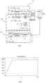
- control circuit diagram is shown to explain a first embodiment of the invention, using control option 3: changing the amplitude and phase position of the output voltage of the converter.
- the motor with the highest speed was used as the reference motor
- a second sub-option for setting an operating point was a speed control over the in the figure 1 shown speed controller 10
- a current phase controller was used, which sets the phase angle ⁇ at the output, specifically for controlling the field-oriented voltage vector in the dq reference coordinate system with a current phase controller 20.
- the fastest i. H. the lightest loaded motor
- it also represents the reference for the reference coordinate system. Choosing the fastest or least heavily loaded motor as the reference motor ensures the highest dynamics in the control system.
- a speed controller is used.
- the speed controller 10 (here in the form of a PI controller) calculates a setpoint voltage u by comparing it with the returned weighted speeds of all motors ⁇ x . This results in a transformation with the phase angle ⁇ ref (i.e. without taking a phase correction into account) only to a voltage in the q direction in the dq coordinate system at the reference motor.
- this voltage leads to a field-forming current component developing in the d-direction and a further torque-forming current component in the q-direction.
- the other motors experience a torque and reach a stable operating point, but this operating point is usually not the most efficient operating point due to the unaffected d component.
- the phase position and thus the phase angle of the output voltage at the converter must still be suitably adjusted.
- a current phase controller 20 is used to adjust the phase position and thus to set a preferred operating point, in order to ensure the desired phase position of the current.
- the current phase controller 20 determines the current field-oriented components of the current in the d-direction and q-direction in relation to the dq reference coordinate system.
- the deviation from the desired target value determined by the phase detector is sent to a controller (eg a PI controller).
- the value ⁇ calculated by the controller 21 for the phase angle now ensures that the d current desired from the point of view of the reference system is set.
- the determined correction angle causes an additional rotation of the set voltage vector. The consequence of this is that there is a negative change in the d-current component in all motors that are running afterward, and these motors develop a greater torque than in the previous, uncorrected operating point. These motors are thus accelerated or increase their speed.
- a positive change in the d-current component is also brought about in all leading EC motors, as a result of which these EC motors develop less torque than in the previous operating point and are therefore braked.
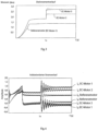
- the reference motor is the fastest EC motor.
- the other two EC motors experience different load jumps, as in FIG figure 3 shown what to a how in the figure 5 speed deviation shown.
- These sudden changes in load are caused by the in the figure 1 shown stabilization controller intercepted.
- the phase controller then ensures that the resulting d current is minimized.
- the field-oriented current flow is on the figure 4 referred.
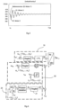
- FIG 6 1 is a control circuit diagram for explaining a second embodiment of the invention with a different control topology in which control option 2: changing the phase position of the output voltage of the converter is used.
- control option 2 changing the phase position of the output voltage of the converter is used.
- the motor with the highest speed was used as the sub-options as the reference motor, speed control was used to set an operating point, and current phase control was used to set the preferred operating point.
- this embodiment includes a limiter for the voltage.
- the stabilization controller calculates a correction angle y stab depending on the differences in speed and angle of rotation. If one of the EC motors now runs after the selected reference motor, the determined correction angle causes an additional rotation of the set voltage pointer. The consequence of this is that there is a negative change in the d-current component in all motors that are running afterward, and these motors develop a greater torque than in the previous, uncorrected operating point. These motors are thus accelerated or increase their speed. A positive change in the d-current component is also brought about in all leading EC motors, as a result of which these EC motors develop less torque than in the previous operating point and are therefore braked.
Landscapes
- Engineering & Computer Science (AREA)
- Power Engineering (AREA)
- Control Of Multiple Motors (AREA)
Claims (7)
- Procédé permettant de réguler et de commander deux ou plusieurs moteurs à commutation électronique, ci-après appelés moteurs EC, qui fonctionnent sur un convertisseur commun, dans lequel une régulation commune avec au moins un régulateur est prévue pour le réglage d'un point de fonctionnement stable ou d'une série de points de fonctionnement stables des moteurs EC,
caractérisé en ce qu'une combinaison d'au moins une option de régulation et d'une sous-option pour cette option de régulation est prévue, une grandeur de régulation représentant alors le réglage de tension à la sortie du convertisseur, dans lequel le réglage de tension à la sortie du convertisseur est effectué à l'aide d'une évaluation de différence d'angle et de vitesse de rotation entre un moteur de référence et au moins l'un des moteurs EC sélectionné parmi les moteurs EC, dans lequel selon une sous-option, la sélection appropriée d'un moteur de référence est effectuée pour la régulation des points de fonctionnement des moteurs EC, et dans lequel on utilise comme système de référence de moteur au choix le moteur ayant la plus haute vitesse de rotation comme moteur de référence, le moteur ayant la plus basse vitesse de rotation, une combinaison pondérée de façon appropriée de plusieurs moteurs EC ou un moteur de référence fictif. - Procédé selon la revendication 1, caractérisé en ce qu'on utilise comme option de régulation pour la mise au point d'un point de fonctionnement préféré des moteurs EC la variation de l'amplitude de la tension de sortie au niveau du convertisseur, la variation de la position de phase de la tension de sortie au niveau du convertisseur ou la variation de l'amplitude et de la position de phase de la tension de sortie à la sortie du convertisseur.
- Procédé selon la revendication 2, caractérisé en ce qu'une autre sous-option est combinée avec l'une des options de régulation définies à la revendication 2, dans lequel une régulation de vitesse de rotation, l'adaptation du niveau de modulation ou une simple régulation de courant est prévue comme une autre sous-option.
- Procédé selon l'une quelconque des revendications 1 à 3, caractérisé en ce que comme une autre sous-option, le fait d'assurer le point de fonctionnement stable comme point de fonctionnement efficace des moteurs EC est effectué par une régulation de phase de courant, une fonction mathématique ou par l'intermédiaire de tableaux de correspondance de valeurs.
- Procédé selon l'une quelconque des revendications 1 à 4, caractérisé en ce qu'au moyen d'un régulateur de vitesse de rotation, la comparaison régulière ou continue de la vitesse de rotation réelle et théorique permet d'assurer que les moteurs EC suivent de façon stable une série libre de points de fonctionnement par l'intermédiaire de la régulation de la tension de sortie du convertisseur.
- Procédé selon l'une quelconque des revendications 1 à 5, caractérisé en ce que le réglage du point de fonctionnement souhaité des moteurs EC est obtenu au moyen de la spécification d'un degré de modulation fixe par le convertisseur.
- Procédé selon l'une quelconque des revendications 4 à 6 pour assurer le point de fonctionnement préféré en utilisant une régulation de phase de courant, dans lequel le courant résultant contient lors de la régulation de phase de courant contient la composante de courant d nécessaire à cet effet dans un système de coordonnées dq, dans lequel le régulateur de phase de courant règle à cet effet au niveau de sa sortie l'angle de phase Δγ entre la composante de courant d et la composante de courant q qui correspond en régime permanent du moteur exactement au décalage de phase ϕ résultant de la sollicitation du moteur.
Applications Claiming Priority (2)
| Application Number | Priority Date | Filing Date | Title |
|---|---|---|---|
| DE102017125317.3A DE102017125317A1 (de) | 2017-10-27 | 2017-10-27 | Mehrmotorenbetrieb |
| PCT/EP2018/079508 WO2019081768A1 (fr) | 2017-10-27 | 2018-10-26 | Entraînement multimoteur |
Publications (2)
| Publication Number | Publication Date |
|---|---|
| EP3669451A1 EP3669451A1 (fr) | 2020-06-24 |
| EP3669451B1 true EP3669451B1 (fr) | 2023-08-09 |
Family
ID=64017383
Family Applications (1)
| Application Number | Title | Priority Date | Filing Date |
|---|---|---|---|
| EP18793428.6A Active EP3669451B1 (fr) | 2017-10-27 | 2018-10-26 | Procede pour un entraînement multimoteur |
Country Status (5)
| Country | Link |
|---|---|
| US (1) | US11233468B2 (fr) |
| EP (1) | EP3669451B1 (fr) |
| CN (1) | CN111201703B (fr) |
| DE (1) | DE102017125317A1 (fr) |
| WO (1) | WO2019081768A1 (fr) |
Family Cites Families (9)
| Publication number | Priority date | Publication date | Assignee | Title |
|---|---|---|---|---|
| US5184057A (en) * | 1989-09-14 | 1993-02-02 | Hitachi, Ltd. | Control method and device for ac motor |
| JP4128891B2 (ja) * | 2003-03-13 | 2008-07-30 | 株式会社東芝 | モータ制御装置 |
| FR2899040B1 (fr) * | 2006-03-24 | 2010-07-30 | Airbus France | Systeme de puissance comportant plusieurs machines synchrones autopilotees de facon synchronisee par un convertisseur et procede de commande d'un tel systeme |
| KR102273139B1 (ko) * | 2014-02-11 | 2021-07-05 | 삼성전자주식회사 | 동력 장치 및 동력 장치에 포함되는 전동기 구동 장치 |
| KR102267061B1 (ko) * | 2014-02-11 | 2021-06-18 | 삼성전자주식회사 | 동력 장치, 동력 장치의 제어방법 및 동력 장치에 포함되는 전동기 구동 장치 |
| KR102272044B1 (ko) * | 2014-02-17 | 2021-07-05 | 삼성전자주식회사 | 단일 인버터를 이용한 복수의 영구 자석 동기식 모터의 구동 장치 및 방법 |
| CN104143937A (zh) * | 2014-08-27 | 2014-11-12 | 北京合康亿盛变频科技股份有限公司 | 无速度传感器矢量控制系统 |
| CN104901600B (zh) * | 2015-05-19 | 2017-10-27 | 南京航空航天大学 | 宽转速范围内永磁同步电机的无位置传感器控制方法 |
| US10389286B2 (en) * | 2016-03-07 | 2019-08-20 | Schlumberger Technology Corporation | Methods and systems for control of parallel connected motor drives |
-
2017
- 2017-10-27 DE DE102017125317.3A patent/DE102017125317A1/de not_active Withdrawn
-
2018
- 2018-10-26 US US16/757,383 patent/US11233468B2/en active Active
- 2018-10-26 CN CN201880065989.0A patent/CN111201703B/zh active Active
- 2018-10-26 EP EP18793428.6A patent/EP3669451B1/fr active Active
- 2018-10-26 WO PCT/EP2018/079508 patent/WO2019081768A1/fr not_active Ceased
Also Published As
| Publication number | Publication date |
|---|---|
| US20200252011A1 (en) | 2020-08-06 |
| CN111201703B (zh) | 2023-09-29 |
| WO2019081768A1 (fr) | 2019-05-02 |
| US11233468B2 (en) | 2022-01-25 |
| CN111201703A (zh) | 2020-05-26 |
| DE102017125317A1 (de) | 2019-05-02 |
| EP3669451A1 (fr) | 2020-06-24 |
Similar Documents
| Publication | Publication Date | Title |
|---|---|---|
| DE2629927C2 (de) | Anordnung zur Drehzahlregelung eines Synchronmotors | |
| DE102008034543A1 (de) | Lineargerät für Feldschwächung in einer Maschine mit internen Permanentmagneten | |
| DE3438504A1 (de) | Verfahren und einrichtung zur regelung einer drehfeldmaschine | |
| DE69630667T2 (de) | Verfahren zur stromregelung von servomotoren | |
| EP0840441B1 (fr) | Régulation à orientation de champ en limite de tension pour une machine à champ tournant | |
| EP2192682B1 (fr) | Contrôle d'une machine synchrone à aimants permanents | |
| CH621656A5 (fr) | ||
| WO2018162195A1 (fr) | Dispositif de régulation pour une machine électrique, système d'entraînement électrique et procédé pour réguler une machine électrique | |
| EP0085871B1 (fr) | Procédé pour augmenter la vitesse maximale d'une machine synchrone pour un champ d'excitation et une tension aux bornes donnés et arrangement pour réaliser ce procédé | |
| EP2347502B1 (fr) | Procede pour faire fonctionner des moteurs synchrones et des appareils associés | |
| DE19725136C2 (de) | Verfahren und Vorrichtung zur Stromregelung einer feldorientiert betriebenen, permanenterregten Synchronmaschine mit trapezförmiger EMK | |
| EP0714162A2 (fr) | Circuit de commande d'une moteur commuté électroniquement | |
| EP3695509B1 (fr) | Procédé pour effectuer un changement entre une commande par bloc et une commande par mli d'une machine électrique | |
| WO2019243265A1 (fr) | Procédé pour commander un générateur d'une éolienne | |
| EP3669451B1 (fr) | Procede pour un entraînement multimoteur | |
| DE102010043297A1 (de) | Elektrische Servolenkungsapparatur | |
| DE202017106551U1 (de) | Mehrmotorenantrieb | |
| WO2022128508A1 (fr) | Procédé et appareil de commande d'un onduleur | |
| DE4413802A1 (de) | Verfahren und Vorrichtung zum Steuern der Drehzahl eines elektrischen Dreiphasen-Asynchronmotors | |
| DE2914613C2 (de) | Schaltungsanordnung zur Regelung von Drehfeldmaschinen | |
| DE3310555A1 (de) | Mehrphasenmotorsteuerung fuer aufzuege | |
| DE10002706A1 (de) | Verfahren zur Steuerung der Umrichterschaltung einer geschalteten Reluktanzmaschine | |
| DE19752940A1 (de) | Verfahren und Vorrichtung zur dynamischen Leistungsregelung einer angetriebenen Synchronmaschine | |
| DE3045575A1 (de) | Verfahren zur steuerung und regelung einer direktumrichtergespeisten synchronmaschine | |
| WO2005114830A1 (fr) | Dispositif convertisseur de frequence pour parc a energie eolienne et procede pour exploiter un tel dispositif |
Legal Events
| Date | Code | Title | Description |
|---|---|---|---|
| STAA | Information on the status of an ep patent application or granted ep patent |
Free format text: STATUS: UNKNOWN |
|
| STAA | Information on the status of an ep patent application or granted ep patent |
Free format text: STATUS: THE INTERNATIONAL PUBLICATION HAS BEEN MADE |
|
| PUAI | Public reference made under article 153(3) epc to a published international application that has entered the european phase |
Free format text: ORIGINAL CODE: 0009012 |
|
| STAA | Information on the status of an ep patent application or granted ep patent |
Free format text: STATUS: REQUEST FOR EXAMINATION WAS MADE |
|
| 17P | Request for examination filed |
Effective date: 20200316 |
|
| AK | Designated contracting states |
Kind code of ref document: A1 Designated state(s): AL AT BE BG CH CY CZ DE DK EE ES FI FR GB GR HR HU IE IS IT LI LT LU LV MC MK MT NL NO PL PT RO RS SE SI SK SM TR |
|
| AX | Request for extension of the european patent |
Extension state: BA ME |
|
| RIN1 | Information on inventor provided before grant (corrected) |
Inventor name: WIEDMANN, GEORG Inventor name: WYSTUP, RALPH Inventor name: WECKERT, MARCO Inventor name: KILIAN, THOMAS Inventor name: SCHROTH, SEBASTIAN |
|
| DAV | Request for validation of the european patent (deleted) | ||
| DAX | Request for extension of the european patent (deleted) | ||
| STAA | Information on the status of an ep patent application or granted ep patent |
Free format text: STATUS: EXAMINATION IS IN PROGRESS |
|
| 17Q | First examination report despatched |
Effective date: 20211122 |
|
| GRAP | Despatch of communication of intention to grant a patent |
Free format text: ORIGINAL CODE: EPIDOSNIGR1 |
|
| STAA | Information on the status of an ep patent application or granted ep patent |
Free format text: STATUS: GRANT OF PATENT IS INTENDED |
|
| INTG | Intention to grant announced |
Effective date: 20221202 |
|
| GRAJ | Information related to disapproval of communication of intention to grant by the applicant or resumption of examination proceedings by the epo deleted |
Free format text: ORIGINAL CODE: EPIDOSDIGR1 |
|
| STAA | Information on the status of an ep patent application or granted ep patent |
Free format text: STATUS: EXAMINATION IS IN PROGRESS |
|
| INTC | Intention to grant announced (deleted) | ||
| GRAP | Despatch of communication of intention to grant a patent |
Free format text: ORIGINAL CODE: EPIDOSNIGR1 |
|
| STAA | Information on the status of an ep patent application or granted ep patent |
Free format text: STATUS: GRANT OF PATENT IS INTENDED |
|
| INTG | Intention to grant announced |
Effective date: 20230309 |
|
| GRAS | Grant fee paid |
Free format text: ORIGINAL CODE: EPIDOSNIGR3 |
|
| P01 | Opt-out of the competence of the unified patent court (upc) registered |
Effective date: 20230525 |
|
| GRAA | (expected) grant |
Free format text: ORIGINAL CODE: 0009210 |
|
| STAA | Information on the status of an ep patent application or granted ep patent |
Free format text: STATUS: THE PATENT HAS BEEN GRANTED |
|
| AK | Designated contracting states |
Kind code of ref document: B1 Designated state(s): AL AT BE BG CH CY CZ DE DK EE ES FI FR GB GR HR HU IE IS IT LI LT LU LV MC MK MT NL NO PL PT RO RS SE SI SK SM TR |
|
| REG | Reference to a national code |
Ref country code: GB Ref legal event code: FG4D Free format text: NOT ENGLISH |
|
| REG | Reference to a national code |
Ref country code: CH Ref legal event code: EP |
|
| REG | Reference to a national code |
Ref country code: IE Ref legal event code: FG4D Free format text: LANGUAGE OF EP DOCUMENT: GERMAN |
|
| REG | Reference to a national code |
Ref country code: DE Ref legal event code: R096 Ref document number: 502018012956 Country of ref document: DE |
|
| REG | Reference to a national code |
Ref country code: NL Ref legal event code: FP |
|
| REG | Reference to a national code |
Ref country code: LT Ref legal event code: MG9D |
|
| PG25 | Lapsed in a contracting state [announced via postgrant information from national office to epo] |
Ref country code: GR Free format text: LAPSE BECAUSE OF FAILURE TO SUBMIT A TRANSLATION OF THE DESCRIPTION OR TO PAY THE FEE WITHIN THE PRESCRIBED TIME-LIMIT Effective date: 20231110 |
|
| PG25 | Lapsed in a contracting state [announced via postgrant information from national office to epo] |
Ref country code: IS Free format text: LAPSE BECAUSE OF FAILURE TO SUBMIT A TRANSLATION OF THE DESCRIPTION OR TO PAY THE FEE WITHIN THE PRESCRIBED TIME-LIMIT Effective date: 20231209 |
|
| PG25 | Lapsed in a contracting state [announced via postgrant information from national office to epo] |
Ref country code: SE Free format text: LAPSE BECAUSE OF FAILURE TO SUBMIT A TRANSLATION OF THE DESCRIPTION OR TO PAY THE FEE WITHIN THE PRESCRIBED TIME-LIMIT Effective date: 20230809 Ref country code: RS Free format text: LAPSE BECAUSE OF FAILURE TO SUBMIT A TRANSLATION OF THE DESCRIPTION OR TO PAY THE FEE WITHIN THE PRESCRIBED TIME-LIMIT Effective date: 20230809 Ref country code: PT Free format text: LAPSE BECAUSE OF FAILURE TO SUBMIT A TRANSLATION OF THE DESCRIPTION OR TO PAY THE FEE WITHIN THE PRESCRIBED TIME-LIMIT Effective date: 20231211 Ref country code: NO Free format text: LAPSE BECAUSE OF FAILURE TO SUBMIT A TRANSLATION OF THE DESCRIPTION OR TO PAY THE FEE WITHIN THE PRESCRIBED TIME-LIMIT Effective date: 20231109 Ref country code: LV Free format text: LAPSE BECAUSE OF FAILURE TO SUBMIT A TRANSLATION OF THE DESCRIPTION OR TO PAY THE FEE WITHIN THE PRESCRIBED TIME-LIMIT Effective date: 20230809 Ref country code: LT Free format text: LAPSE BECAUSE OF FAILURE TO SUBMIT A TRANSLATION OF THE DESCRIPTION OR TO PAY THE FEE WITHIN THE PRESCRIBED TIME-LIMIT Effective date: 20230809 Ref country code: IS Free format text: LAPSE BECAUSE OF FAILURE TO SUBMIT A TRANSLATION OF THE DESCRIPTION OR TO PAY THE FEE WITHIN THE PRESCRIBED TIME-LIMIT Effective date: 20231209 Ref country code: HR Free format text: LAPSE BECAUSE OF FAILURE TO SUBMIT A TRANSLATION OF THE DESCRIPTION OR TO PAY THE FEE WITHIN THE PRESCRIBED TIME-LIMIT Effective date: 20230809 Ref country code: GR Free format text: LAPSE BECAUSE OF FAILURE TO SUBMIT A TRANSLATION OF THE DESCRIPTION OR TO PAY THE FEE WITHIN THE PRESCRIBED TIME-LIMIT Effective date: 20231110 Ref country code: FI Free format text: LAPSE BECAUSE OF FAILURE TO SUBMIT A TRANSLATION OF THE DESCRIPTION OR TO PAY THE FEE WITHIN THE PRESCRIBED TIME-LIMIT Effective date: 20230809 |
|
| PG25 | Lapsed in a contracting state [announced via postgrant information from national office to epo] |
Ref country code: PL Free format text: LAPSE BECAUSE OF FAILURE TO SUBMIT A TRANSLATION OF THE DESCRIPTION OR TO PAY THE FEE WITHIN THE PRESCRIBED TIME-LIMIT Effective date: 20230809 |
|
| PG25 | Lapsed in a contracting state [announced via postgrant information from national office to epo] |
Ref country code: ES Free format text: LAPSE BECAUSE OF FAILURE TO SUBMIT A TRANSLATION OF THE DESCRIPTION OR TO PAY THE FEE WITHIN THE PRESCRIBED TIME-LIMIT Effective date: 20230809 |
|
| PG25 | Lapsed in a contracting state [announced via postgrant information from national office to epo] |
Ref country code: SM Free format text: LAPSE BECAUSE OF FAILURE TO SUBMIT A TRANSLATION OF THE DESCRIPTION OR TO PAY THE FEE WITHIN THE PRESCRIBED TIME-LIMIT Effective date: 20230809 Ref country code: RO Free format text: LAPSE BECAUSE OF FAILURE TO SUBMIT A TRANSLATION OF THE DESCRIPTION OR TO PAY THE FEE WITHIN THE PRESCRIBED TIME-LIMIT Effective date: 20230809 Ref country code: ES Free format text: LAPSE BECAUSE OF FAILURE TO SUBMIT A TRANSLATION OF THE DESCRIPTION OR TO PAY THE FEE WITHIN THE PRESCRIBED TIME-LIMIT Effective date: 20230809 Ref country code: EE Free format text: LAPSE BECAUSE OF FAILURE TO SUBMIT A TRANSLATION OF THE DESCRIPTION OR TO PAY THE FEE WITHIN THE PRESCRIBED TIME-LIMIT Effective date: 20230809 Ref country code: DK Free format text: LAPSE BECAUSE OF FAILURE TO SUBMIT A TRANSLATION OF THE DESCRIPTION OR TO PAY THE FEE WITHIN THE PRESCRIBED TIME-LIMIT Effective date: 20230809 Ref country code: CZ Free format text: LAPSE BECAUSE OF FAILURE TO SUBMIT A TRANSLATION OF THE DESCRIPTION OR TO PAY THE FEE WITHIN THE PRESCRIBED TIME-LIMIT Effective date: 20230809 Ref country code: SK Free format text: LAPSE BECAUSE OF FAILURE TO SUBMIT A TRANSLATION OF THE DESCRIPTION OR TO PAY THE FEE WITHIN THE PRESCRIBED TIME-LIMIT Effective date: 20230809 |
|
| REG | Reference to a national code |
Ref country code: DE Ref legal event code: R097 Ref document number: 502018012956 Country of ref document: DE |
|
| PG25 | Lapsed in a contracting state [announced via postgrant information from national office to epo] |
Ref country code: MC Free format text: LAPSE BECAUSE OF FAILURE TO SUBMIT A TRANSLATION OF THE DESCRIPTION OR TO PAY THE FEE WITHIN THE PRESCRIBED TIME-LIMIT Effective date: 20230809 |
|
| REG | Reference to a national code |
Ref country code: CH Ref legal event code: PL |
|
| PLBE | No opposition filed within time limit |
Free format text: ORIGINAL CODE: 0009261 |
|
| STAA | Information on the status of an ep patent application or granted ep patent |
Free format text: STATUS: NO OPPOSITION FILED WITHIN TIME LIMIT |
|
| REG | Reference to a national code |
Ref country code: BE Ref legal event code: MM Effective date: 20231031 |
|
| PG25 | Lapsed in a contracting state [announced via postgrant information from national office to epo] |
Ref country code: LU Free format text: LAPSE BECAUSE OF NON-PAYMENT OF DUE FEES Effective date: 20231026 |
|
| PG25 | Lapsed in a contracting state [announced via postgrant information from national office to epo] |
Ref country code: LU Free format text: LAPSE BECAUSE OF NON-PAYMENT OF DUE FEES Effective date: 20231026 |
|
| 26N | No opposition filed |
Effective date: 20240513 |
|
| PG25 | Lapsed in a contracting state [announced via postgrant information from national office to epo] |
Ref country code: CH Free format text: LAPSE BECAUSE OF NON-PAYMENT OF DUE FEES Effective date: 20231031 |
|
| PG25 | Lapsed in a contracting state [announced via postgrant information from national office to epo] |
Ref country code: CH Free format text: LAPSE BECAUSE OF NON-PAYMENT OF DUE FEES Effective date: 20231031 Ref country code: SI Free format text: LAPSE BECAUSE OF FAILURE TO SUBMIT A TRANSLATION OF THE DESCRIPTION OR TO PAY THE FEE WITHIN THE PRESCRIBED TIME-LIMIT Effective date: 20230809 |
|
| PG25 | Lapsed in a contracting state [announced via postgrant information from national office to epo] |
Ref country code: BE Free format text: LAPSE BECAUSE OF NON-PAYMENT OF DUE FEES Effective date: 20231031 |
|
| PG25 | Lapsed in a contracting state [announced via postgrant information from national office to epo] |
Ref country code: IE Free format text: LAPSE BECAUSE OF NON-PAYMENT OF DUE FEES Effective date: 20231026 |
|
| PG25 | Lapsed in a contracting state [announced via postgrant information from national office to epo] |
Ref country code: IE Free format text: LAPSE BECAUSE OF NON-PAYMENT OF DUE FEES Effective date: 20231026 |
|
| PG25 | Lapsed in a contracting state [announced via postgrant information from national office to epo] |
Ref country code: BG Free format text: LAPSE BECAUSE OF FAILURE TO SUBMIT A TRANSLATION OF THE DESCRIPTION OR TO PAY THE FEE WITHIN THE PRESCRIBED TIME-LIMIT Effective date: 20230809 |
|
| PG25 | Lapsed in a contracting state [announced via postgrant information from national office to epo] |
Ref country code: BG Free format text: LAPSE BECAUSE OF FAILURE TO SUBMIT A TRANSLATION OF THE DESCRIPTION OR TO PAY THE FEE WITHIN THE PRESCRIBED TIME-LIMIT Effective date: 20230809 |
|
| PG25 | Lapsed in a contracting state [announced via postgrant information from national office to epo] |
Ref country code: CY Free format text: LAPSE BECAUSE OF FAILURE TO SUBMIT A TRANSLATION OF THE DESCRIPTION OR TO PAY THE FEE WITHIN THE PRESCRIBED TIME-LIMIT; INVALID AB INITIO Effective date: 20181026 |
|
| PG25 | Lapsed in a contracting state [announced via postgrant information from national office to epo] |
Ref country code: HU Free format text: LAPSE BECAUSE OF FAILURE TO SUBMIT A TRANSLATION OF THE DESCRIPTION OR TO PAY THE FEE WITHIN THE PRESCRIBED TIME-LIMIT; INVALID AB INITIO Effective date: 20181026 |
|
| PGFP | Annual fee paid to national office [announced via postgrant information from national office to epo] |
Ref country code: NL Payment date: 20251023 Year of fee payment: 8 |
|
| PG25 | Lapsed in a contracting state [announced via postgrant information from national office to epo] |
Ref country code: TR Free format text: LAPSE BECAUSE OF FAILURE TO SUBMIT A TRANSLATION OF THE DESCRIPTION OR TO PAY THE FEE WITHIN THE PRESCRIBED TIME-LIMIT Effective date: 20230809 |
|
| PGFP | Annual fee paid to national office [announced via postgrant information from national office to epo] |
Ref country code: DE Payment date: 20251020 Year of fee payment: 8 |
|
| PGFP | Annual fee paid to national office [announced via postgrant information from national office to epo] |
Ref country code: GB Payment date: 20251024 Year of fee payment: 8 |
|
| PGFP | Annual fee paid to national office [announced via postgrant information from national office to epo] |
Ref country code: AT Payment date: 20251021 Year of fee payment: 8 |
|
| PGFP | Annual fee paid to national office [announced via postgrant information from national office to epo] |
Ref country code: IT Payment date: 20251031 Year of fee payment: 8 |
|
| PGFP | Annual fee paid to national office [announced via postgrant information from national office to epo] |
Ref country code: FR Payment date: 20251024 Year of fee payment: 8 |