EP3669518B1 - Konfigurierbare multifunktionelle robuste voice-over-internetprotokoll (voip)-kommunikationsvorrichtung mit universeller anwendungsplattform - Google Patents
Konfigurierbare multifunktionelle robuste voice-over-internetprotokoll (voip)-kommunikationsvorrichtung mit universeller anwendungsplattform Download PDFInfo
- Publication number
- EP3669518B1 EP3669518B1 EP18846113.1A EP18846113A EP3669518B1 EP 3669518 B1 EP3669518 B1 EP 3669518B1 EP 18846113 A EP18846113 A EP 18846113A EP 3669518 B1 EP3669518 B1 EP 3669518B1
- Authority
- EP
- European Patent Office
- Prior art keywords
- voip
- unit
- units
- call
- mode
- Prior art date
- Legal status (The legal status is an assumption and is not a legal conclusion. Google has not performed a legal analysis and makes no representation as to the accuracy of the status listed.)
- Active
Links
Images










Classifications
-
- G—PHYSICS
- G06—COMPUTING OR CALCULATING; COUNTING
- G06F—ELECTRIC DIGITAL DATA PROCESSING
- G06F3/00—Input arrangements for transferring data to be processed into a form capable of being handled by the computer; Output arrangements for transferring data from processing unit to output unit, e.g. interface arrangements
- G06F3/01—Input arrangements or combined input and output arrangements for interaction between user and computer
- G06F3/03—Arrangements for converting the position or the displacement of a member into a coded form
- G06F3/033—Pointing devices displaced or positioned by the user, e.g. mice, trackballs, pens or joysticks; Accessories therefor
- G06F3/0354—Pointing devices displaced or positioned by the user, e.g. mice, trackballs, pens or joysticks; Accessories therefor with detection of two-dimensional [2D] relative movements between the device, or an operating part thereof, and a plane or surface, e.g. 2D mice, trackballs, pens or pucks
- G06F3/03547—Touch pads, in which fingers can move on a surface
-
- G—PHYSICS
- G06—COMPUTING OR CALCULATING; COUNTING
- G06F—ELECTRIC DIGITAL DATA PROCESSING
- G06F3/00—Input arrangements for transferring data to be processed into a form capable of being handled by the computer; Output arrangements for transferring data from processing unit to output unit, e.g. interface arrangements
- G06F3/01—Input arrangements or combined input and output arrangements for interaction between user and computer
- G06F3/03—Arrangements for converting the position or the displacement of a member into a coded form
- G06F3/041—Digitisers, e.g. for touch screens or touch pads, characterised by the transducing means
- G06F3/0412—Digitisers structurally integrated in a display
-
- H—ELECTRICITY
- H04—ELECTRIC COMMUNICATION TECHNIQUE
- H04L—TRANSMISSION OF DIGITAL INFORMATION, e.g. TELEGRAPHIC COMMUNICATION
- H04L65/00—Network arrangements, protocols or services for supporting real-time applications in data packet communication
- H04L65/1066—Session management
- H04L65/1101—Session protocols
- H04L65/1104—Session initiation protocol [SIP]
-
- H—ELECTRICITY
- H04—ELECTRIC COMMUNICATION TECHNIQUE
- H04M—TELEPHONIC COMMUNICATION
- H04M1/00—Substation equipment, e.g. for use by subscribers
- H04M1/02—Constructional features of telephone sets
- H04M1/18—Telephone sets specially adapted for use in ships, mines, or other places exposed to adverse environment
- H04M1/185—Improving the shock resistance of the housing, e.g. by increasing the rigidity
-
- H—ELECTRICITY
- H04—ELECTRIC COMMUNICATION TECHNIQUE
- H04M—TELEPHONIC COMMUNICATION
- H04M1/00—Substation equipment, e.g. for use by subscribers
- H04M1/253—Telephone sets using digital voice transmission
- H04M1/2535—Telephone sets using digital voice transmission adapted for voice communication over an Internet Protocol [IP] network
-
- H—ELECTRICITY
- H04—ELECTRIC COMMUNICATION TECHNIQUE
- H04L—TRANSMISSION OF DIGITAL INFORMATION, e.g. TELEGRAPHIC COMMUNICATION
- H04L65/00—Network arrangements, protocols or services for supporting real-time applications in data packet communication
- H04L65/1066—Session management
- H04L65/1101—Session protocols
-
- H—ELECTRICITY
- H04—ELECTRIC COMMUNICATION TECHNIQUE
- H04M—TELEPHONIC COMMUNICATION
- H04M2250/00—Details of telephonic subscriber devices
- H04M2250/22—Details of telephonic subscriber devices including a touch pad, a touch sensor or a touch detector
-
- H—ELECTRICITY
- H04—ELECTRIC COMMUNICATION TECHNIQUE
- H04M—TELEPHONIC COMMUNICATION
- H04M3/00—Automatic or semi-automatic exchanges
- H04M3/42—Systems providing special services or facilities to subscribers
- H04M3/56—Arrangements for connecting several subscribers to a common circuit, i.e. affording conference facilities
- H04M3/567—Multimedia conference systems
Definitions
- the present invention relates to an Internet Protocol or IP-based telephone unit or station configured to be pre-programmed to operate in a plurality of modes and have a touch screen display for universal form factor regardless of selected operational mode.
- the present invention relates also to a ruggedized IP-based telephone unit or station with touch screen display.
- a railway system can have a number of robust analog telephones installed at one or more train station(s), along passenger platforms, in service or maintenance areas, and along the railway track (i.e., trackside), and therefore generally exposed to various weather conditions and possible vandalism.
- hazardous locations can be industrial sites such as land and offshore oil rigs, chemical plants, refineries, mills, and loading facilities, which can be subjected to harsh environments, as well as create potentially unsafe environments due to the presence of gases or other combustible materials.
- Such communications equipment often needs to be hazardous area (HA) compliant with hazardous area standards promulgated by various safety standards organizations (e.g., Underwriters Laboratories (UL)) using various classifications or certifications that regulate the design of equipment used in potentially explosive atmospheres and/or under other unsafe environmental conditions such as the use of electrical equipment in the vicinity of water, the risk of personal injury from moving or falling parts, or even the presence of biological hazards.
- HA hazardous area
- UL Underwriters Laboratories
- Some example certification organizations and/or schemes for equipment used in classified hazardous locations can include, but are not limited to, the United States (National Electrical Code), Canada (Canadian Electrical Code), Europe (CENELEC EN60079-10) and throughout the world (IEC 60079-10), ATEX directives 94/9/EC and 1999/92/EC in the European Union, North America laboratories such as Intertek (ETL), Factory Mutual (FM), Canadian Standards Association (CSA) and the IECEx International Certification Scheme.
- ETL Intertek
- FM Factory Mutual
- CSA Canadian Standards Association
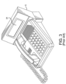
- Existing communications equipment ruggedized for use in weather extremes and/or hazardous locations comprises a unit or station that is typically wall mounted and relatively simple in form factor such as a housing having a hands free configuration as illustrated in Figs. 1A, 1B, 1D and 1E , or handset configuration as illustrated in Figs. 1C, 1F and 1G , and having, for example, user buttons for dialing as illustrated in Figs. 1A, 1C, 1E and 1G .
- some telephone units or stations with handsets can have a no button configuration (e.g., Fig.
- Operators of communication networks along transit systems or at industrial locations can find a page party function to be useful, that is, the ability for multiple telephones or user stations to be involved on the same call.
- An approach that allows multiple telephones or user stations to be involved on the same call uses a network backbone as the communications infrastructure and Voice over Internet Protocol (VoIP) devices. With such networks, multiple channels can be utilized over a single cable. It can be possible to deploy multiple IP devices across an existing network backbone, reducing the cost of added infrastructure significantly.
- VoIP Voice over Internet Protocol
- Fig. 2 depicts an example GAI-Tronics Corporation system deploying VoIP stations 5 connected to a network switch 9 via CAT5/CAT5E cable or fiber optic cable indicated at 11, for example, and to a network backbone 7 via the network switch 9.
- the VoIP stations 5 can be provided with a loudspeaker 6 (e.g., an 8 ohm speaker) and powered via a local power source 8, for example.
- a loudspeaker 6 e.g., an 8 ohm speaker
- FIG. 1A through 1G illustrate some examples of GAI-Tronics Corporation's weather-resistant and vandal-resistant outdoor stations 5 that can provide VoIP paging and/or intercom functions.
- the units or stations 5 have minimal buttons (i.e., in some instances, only a "Help" or "Call” button 10 as shown in Figs. 1B and 1D , or only a hot dial configuration as shown in Fig. 1F ).
- key pads 12 e.g., Figs. 1A, 1C, 1D
- a display screen would be useful to show dialed party or incoming call party information.
- Existing ruggedized VoIP products do not have a touch screen or even a liquid crystal display (LCD). Instead, existing VoIP solutions only provide VoIP functionality at desktop consoles that cannot withstand environments associated with exposed elements (e.g., railway system communications), or industrial plant environments, or classified hazardous area (HA) environments where the VoIP desktop consoles may be subjected to extreme weather conditions (e.g., precipitation, wind), extreme temperatures, vandalism, among other harsh conditions.
- An example conventional VoIP desktop solution for an access panel having an LCD display 14 is shown in Fig. 3 .
- the access panel is typically programmed at a system control cabinet and its operating capabilities can include: voice paging, party line communication (e.g., with other access panels or Page/Party ® stations available from GAI-Tronics Corporation, Reading, Pennsylvania), activation/reset of emergency alarms, and a text display of the system operating status on the LCD display.
- the access panel speaker can also broadcast page and alarm audio.
- the access panel and LCD display will not withstand environments associated with harsh weather conditions, harsh industrial plant environments, or classified hazardous area (HA) environments.
- form factors for communications devices can vary significantly, depending on whether the housing is weather-protected or HA-compliant, whether the device is hands free or uses a handset, and whether the device employs hot dialing or needs different configurations of buttons to specify zones or parties for paging or point-to-point communications or setting alarms.
- VoIP system designers' costs increase with each different form factor type needed to achieve a particular VoIP system function in the various environments where the VoIP systems are deployed.
- a need also exists for a ruggedized communications device having VoIP functionality and a touch screen user interface that can withstand environments associated with exposed elements, or industrial plant environments, or classified hazardous area (HA) environments. Ruggedized equipment developed for operating in such potentially harsh environments is expensive to manufacture since it needs to include ruggedized components and housings that can be more costly because of their robust and often superior materials and/or additional components. Thus, a need also exists for a communications unit that is configurable to provide one or more of plural selected functions to avoid specialized and often more costly hardware for these types of harsh environments.
- VoIP voice over internet protocol
- a configurable, a configurable, multi-function voice over internet protocol (VoIP) unit comprises a VoIP control module for controlling VoIP operations of the VoIP unit with respect to other VoIP units in an Internet Protocol (IP) network.
- the VoIP control module is configured to operate the VoIP unit in a plurality of modes by selectively participating in at least one of point-to-point communication between the VoIP unit and another one of the VoIP units in the IP network and multicast communication between the VoIP unit and a plurality of the VoIP units depending on which of the plurality of modes the VoIP unit is currently operating in.
- the plurality of modes comprises at least two of a serverless page-party (SP2) station mode, an access panel mode, and a serverless point-to-point intercom mode.
- SP2 serverless page-party
- the VoIP unit also comprises a speaker coupled to the VoIP control module and configured for audio output; a microphone coupled to the VoIP control module and configured to receive audio input; a touch screen display coupled to the VoIP control module and configured to operate a graphical user interface to generate display screens corresponding to the currently selected one of the plurality of modes and to receive user inputs via the display screens; and an IP network interface module connected to the VoIP control module and the IP network.
- the IP network interface module is configured to exchange bi-directional Ethernet data between the IP network and the VoIP control module and to condition audio signals received the IP network for output via the speaker and to condition audio signals input via the microphone for transmission via the IP network.
- the touch screen display comprises a panel screen made from an impact-resistant material.
- the touch screen display comprises a touch screen optically bonded to a liquid crystal display.
- the VoIP unit further comprises a ruggedized housing having the touch screen display mounted thereto on an external surface thereof and configured in accordance with Class 1, Division 2 classification in the National Fire Protection Association (NFPA) Publication 70, National Electric Code ® (NEC).
- NFPA National Fire Protection Association
- NEC National Electric Code ®
- the VoIP unit further comprises a video camera sensor and lens.
- the VoIP control module is configured to send video call data from the video camera sensor and lens to at least one of the VoIP units in the IP network and to receive video call data from the at least one of the VoIP units that also comprises a video camera sensor and lens.
- the touch screen display is configured to generate at least one graphical user display screen providing at least one input button selected from the group consisting of a telephone keypad of numbered buttons to place dial-pad telephone calls, at least one button to place an auto-dialed call, a directory lookup table that allows the user to select and auto-dial a listed call recipient, a button for placing a multiple line call, and a button for call transfer.
- the VoIP control module is configured to establish at least one of the point-to-point communication and the multicast communication with at least one of the other VoIP units depending on activation of the at least one input button.
- the touch screen display is configured to generate at least one graphical user display screen providing at least one input button selected from the group consisting of buttons corresponding to respective ones of a plurality of party lines, and buttons for selecting at least one paging destination, wherein the paging destination buttons are labeled with at least one of a zone number and an alphanumeric destination name.
- the VoIP control module is configured to establish at least one of the point-to-point communication and the multicast communication with corresponding ones of the other VoIP units depending on activation of the at least one input button.
- the touch screen display is configured to generate at least one graphical user display screen providing at least one input button selected from the group consisting of buttons corresponding to different zones to select to receive a broadcast or intercom message, buttons corresponding to respective different types of alarms, and access panel control buttons for at least one of alarm cancel, acknowledgement, mute, and type of speech.
- the VoIP control module is configured to establish at least one of the point-to-point communication and the multicast communication with corresponding ones of the other VoIP units depending on activation of the at least one input button.
- the touch screen display is configured to generate at least one graphical user display screen providing a directory lookup table that allows the user to select and dial a listed call recipient.
- the VoIP control module is configured to establish the point-to-point communication with corresponding ones of the other VoIP units depending on activation of respective call recipient buttons in the directory lookup table.
- the VoIP control module is configured to operate the VoIP unit in a transit system communication mode selected from the group consisting of a driver communication mode for establishing calls from a driver to crew members, a crew communication mode for establishing calls from at least one of the crew members to the driver or another one of the crew members, a passenger communication mode for establishing calls from a passenger to at least one of the crew members, and a public address mode for transmitting an announcement to the other VoIP units.
- a transit system communication mode selected from the group consisting of a driver communication mode for establishing calls from a driver to crew members, a crew communication mode for establishing calls from at least one of the crew members to the driver or another one of the crew members, a passenger communication mode for establishing calls from a passenger to at least one of the crew members, and a public address mode for transmitting an announcement to the other VoIP units.
- the VoIP unit further comprises a handset having the speaker and the microphone, and a cradle configured to operate a switch that, when the handset is removed from the cradle, generates a signal to the VoIP control module to initiate at least one of a page and a party call to at least one of the VoIP units operated by a crew member, when the VoIP unit is configured to operate in the driver communication mode.
- the touch screen display is configured to generate at least one graphical user display screen providing a selection button to initiate a call to at least one of the VoIP units operated by a crew member and, in response to activation of the selection button, when the VoIP unit is configured to operate in the driver communication mode.
- the VoIP control module when the VoIP control module is configured to operate in the transit system communication mode, the VoIP control module operates via the SP2 station mode to connect VoIP units operated by respective ones of the driver and crew members by distributing a system configuration among the VoIP unit and the other VoIP units that designates IP addresses to respective ones of the VoIP unit and the other VoIP units and designates multicast addresses of page and party line sockets employed by the VoIP unit with respect to the other VoIP units to participate in party calls between the driver and crew members and to provide page announcements via the VoIP units.
- the VoIP control unit when the VoIP unit is configured in accordance with the SP2 station mode, the VoIP control unit is configured to be self-aware of other VoIP units by using a common channel to send or receive the system configuration.
- the touch screen display is configured to generate at least one graphical user display screen providing at least one input button selected from the group consisting of a driver call button, a crew member call button, at least one page zone button, and a page all zones button.
- the VoIP control module is configured to establish at least one of the point-to-point communication and the multicast communication with corresponding ones of the other VoIP units depending on activation of the at least one input button.
- the touch screen display is configured to generate at least one indicator indicating that the VoIP unit has a connection to the IP network, and when an incoming call is being received from at least one of the driver, another crew member, a call for aid button activated on one of the VoIP units, and a page established on one of the VoIP units.
- the touch screen display is configured to generate at least one graphical user display screen indicating that the VoIP unit has established a driver call to the VoIP units being operated by crew members, and to generate at least one indicator indicating that the VoIP unit has an incoming call from one of the VoIP units being operated by a crew member and at least one input screen area to activate to answer the incoming call during the driver call.
- the touch screen display is configured to generate at least one indicator selected from the group consisting of an indicator indicating that the VoIP unit has a connection to the IP network, and an indicator indicating that an incoming call is being received from one of the VoIP units being operated by a crew member.
- the touch screen display is configured to generate at least one graphical user display screen indicating when a page address is being generated.
- the touch screen display is configured to generate at least one indicator indicating that the VoIP unit has a connection to the IP network, and that an incoming call is being received from at least one of the driver, another crew member, a call for aid button activated on one of the VoIP units, and a page established on one of the VoIP units.
- the touch screen display is configured to generate at least one graphical user display screen indicating at least one of an advertisement, and an exit sign having at least one of alphanumeric characters and directional arrows relating to an exit from the transit system.
- the touch screen display is configured to display information received via internet.
- the present invention may comprise VoIP telephone units and systems and methods for operating same having one or more of the above aspects, and/or one or more of the features and combinations thereof.
- the present invention may comprise one or more of the features and/or combinations of the above aspects as recited, for example, in the attached claims.
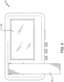
- embodiments of the present invention advantageously provide a configurable, multi-function IP-based communication unit 16 with touch screen display, common or universal hardware set form factor, and universal application platform (UAP) 98 ( Fig. 5 ), which can be configured for use in any of a plurality of operational modes, and can be ruggedized for use in harsh environments.
- UAP universal application platform
- the universal hardware set form factor enables the IP-based communication product to be optimized for commercial use, that is, easily adapted for different applications and environments using a minimal number of housing configurations or features (e.g., tactile buttons or dials).
- the IP-based product or unit 16 is designed to operate as a multi-function device over Ethernet that is configurable to operate in any of a plurality of operational modes.
- the operational modes can include, but are not limited to, VoIP telephone, video streaming for video calls, intercom, alarm activation for a central public address/general alarm (PA/GA) system, a "serverless" page-party (SP2) system, voice product with flash memory, product with conference function, and so on, for example, all by utilizing graphical user interface (GUI) screens 20 on a touch screen display 46 that are designed specifically for each operational mode.
- GUI graphical user interface
- the IP-based product or unit 16 has a common hardware set of components as exemplified in Fig.
- each of the operational modes is programmed (e.g., providing software instructions stored in a memory structure 94 of the control module 44 for a universal application platform 98) or otherwise configured into the unit 16 and implemented using GUI screens 20 developed for that operational mode and generated on the touch screen display 46.
- These operational modes and related GUI screens 20 can be considered a multi-function device transformer since they essentially transform the IP-based unit 16 into a particular type of VoIP-based station or product, while allowing for minimal changes to the housing hardware apart from deciding whether the IP-based unit 16 is hands free ( Fig. 7 ) or has a handset 61 ( Fig.
- the degree of ruggedness of the housing e.g., HA-compliant, vandal-resistant or merely weather-resistant, or configured only for indoor use in non-HA environments.
- the ability to perform each of these functions or operational modes in one unit 16 utilizing a dynamic user interface 20 not only eases installation of such units 16, which can include the hazardous and extreme environments, but also reduces the actual number of different products the end-customer must acquire to achieve all or some of these functions in a communications system installation and also simplifies purchase and inventory of any replacement units for an installed system.
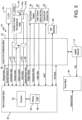
- a VoIP telephone unit 16 can be provided, for example, with a control block or module 44, a signal conditioning block or module 42, a power block or module 40 and a handset 61 or hands free microphone 61b and speaker 61a.
- the control module 44 is described in more detail below.
- the signal conditioning module 42 is connected to an Ethernet network wirelessly or using fiber optic cable or copper, for example, via an Ethernet interface 14.
- the unit 16 is provided with a touch screen display 46, optional LEDs 84 (not shown), and an optional video camera sensor and lens 48, and an external user interface port 50.
- the unit 16 can have a power block or module 40 to receive power via Power over the Ethernet (PoE) or POE Plus, although other power sources can be used such as an external power source.
- a wireless communication interface (e.g., IEEE 802.11, WiFi, Bluetooth TM or other protocol) 60 can be provided to allow wireless communication between the unit 16 and another device such as a smart phone, sensor, Internet of Things (IoT) device, and so on.
- the touch screen display 46 can be ruggedized, that is, it can consist of an impact-resistant screen or screen layer, for example, whereby the glass is laminated or bonding is used to prevent glass breakage from breaking any seal deployed inside the unit 16 for HA-compliance reasons.
- the touch screen display 46 can be an automobile-grade liquid crystal display (LCD) screen (e.g., a 7" display) capable of withstanding a considerable range of temperatures (e.g., -30° C to 70° C), and having optional full sun and/or wide view visibility, that is expected in the automobile environment.
- LCD liquid crystal display
- the display 46 is mounted in a housing of a unit 16 to withstand vandalism and weather and, as needed, to comply with HA classification requirements.
- the touch screen of the touch screen display 46 is optically bonded to a liquid crystal display (LCD) to remove an air gap that can occur between a touch screen and an LCD in many applications when, for example, the touch screen is adhered to an LCD by its edges.
- LCD liquid crystal display
- the unit 16 is not susceptible to moisture that can accumulate in an LCD air gap due to certain external conditions, making the unit 16 more weather-persistent than display devices having an air gap.
- the unit 16 is provided with a magnetic hook switch sensor (e.g., coupled to the handset 61's cradle, not shown), the output 63 of which can be coupled to the signal conditioning block or module 42 for providing on-hook/off-hook status data of the handset 61 to the control module 44.
- the signal conditioning module 42 is configured to provide public address (PA) speaker audio 68, as well as earpiece/speaker audio 62 from the control module 44 for the handset 61 or hands free speaker 61a and receive microphone audio 64 from the handset 61 or separate microphone 61b for the control module 44.
- the signal conditioning module 42 is also configured to provide input data from the touch screen 46 and DC power to the VoIP control board 44.
- General Purpose Monitored Inputs/Outputs (I/O) are provided as generally indicated at 54.
- the signal conditioning module 42 and the control module 44 are configured to process Ethernet data 58.
- the control module 44 in a unit 16 comprises a programmable processor 92 and integral or separate memory 94.
- the microprocessor 92 can be, for example, a digital signal processor (DSP) or system on chip (SOC) with standard VoIP/SIP software.
- the control module 44 can employ, for example, an audio CODEC (e.g., 8kHz G711A/U Law) to provide full duplex hands free speech; that is, when in a call, the units 16's audio will be full duplex (i.e., transmit and receive simultaneously with no switching).
- an audio CODEC e.g., 8kHz G711A/U Law
- the units 16 are programmed (e.g., via software code instructions executed by their respective processors 92 and, for example, in accordance with a universal application platform 98) to establish and terminate point-to-point calls and participate in party line calls, among other operations in accordance with each of the plurality of operational modes.
- the VoIP telephone unit 16 is a configurable multi-function device with universal application platform 98 that is pre-programmed to operate in any of a plurality of modes of operation.
- the plurality of operational modes can be, but are not limited to, two of more of the following modes: a serverless page-party station mode, an access panel mode, and a serverless point-to-point intercom mode, and so on.
- the units 16 are configured to operate as different transit system communication units 16 for different types of users in a transit system such as train car drivers, crew members, passengers and for different locations (e.g., on-board train communications units, trackside units and transit station or platform units), and can also optionally operate in an advertisement or other signage mode (e.g., EXIT signage, advertisement, schedule or other information).
- a transit system communication unit 15 can be implemented to perform one or more of these operational modes but also using dedicated input buttons and indicators instead of a GUI 20 on a touch screen display 46, in accordance with another illustrative embodiment described in connection with Fig. 13 .
- SP2 Serverless Page/Party
- the IP-based unit 16 is configured in a housing with a handset 61, but could also be hands free with a speaker/microphone as indicated at 61a and 61b in Fig. 7 .
- the GUI screen 100 in Fig. 6 shows operational mode selection buttons 102 with the SP2 mode button 104 selected on an SP2 mode screen.
- the SP2 mode screen 100 in Fig. 6 includes party line buttons 106 (e.g., five buttons although a different number of party line buttons can be provided) and paging destinations indicated at 108.
- the unit 16 provides the functionality of the SP2 stations with hardwired user inputs (e.g., buttons, dials, switches) currently available from GAI-Tronics Corporation in Reading, Pennsylvania, and described in commonly-owned WO 2016/100795 .
- hardwired user inputs e.g., buttons, dials, switches
- an IP-based unit 16 when operated per the UAP 98 to be a serverless page party (SP2) unit with regard to connections to other page party units 16 in a network, the page party units 16 can be configured to be self-aware of each other, via a mutual provisioning mode distribution of a system configuration to these page party units 16 that designates unit IP addresses for point-to-point calls as well as multicast addresses of page and party line sockets, thereby eliminating the need for employing a SIP server or IP-PBX to connect to each other.
- SP2 serverless page party
- a common channel can be used by all VoIP units 16 in a system and at least one of the units 16 in the system is designated as a master unit to send the system configuration to the other units 16 via the common channel following their initializations. Since the need for a conference bridge and the additional time needed to set up a conference in older systems is obviated by units 16 configured in this manner, the units 16 are also advantageous because multicast is instantaneously available on a party line, making the page party unit 16 essentially real-time operational.
- the unit 16 In addition to providing the functions of the SP2 stations with hard-wired user input buttons currently available from GAI-Tronics Corporation, the unit 16 also provides several enhancements in the SP2 mode of operation. These enhancements include, but are not limited to, for example, the ability to access more than the current maximum of five party lines indicated at 106. Instead of party lines being numbered 1 through 5 via a hardwired dial, they can now be named using GUI screens on the touch screen display 46. In addition, the unit 16 can indicate on the GUI screens those party lines that are currently in use by others to allow quick party-line selection. The example illustrated unit 16 has the ability to transmit to 5 page zones that are numbered 1 through 5.
- zones can be also named (e.g., alphanumerically and/or using GUI symbols).
- the display 46 can indicate which zones have activity and which zone is currently being broadcast through the unit 16's amplifier and speaker 61.
- SP2 is a paging and intercom system that combines the simplicity of "press to page, release to party" operation with multicast Voice over Internet Protocol (VoIP) technology to provide virtually instant communication in the most demanding of environments.
- SP2 is wired to the nearest network switch using CAT5/CAT5E Ethernet cable or Fiber Optic Cable, for example, or wirelessly connected.
- Local power is supplied to each station either as a separate power cable or contained in a hybrid power / network cable or via a power supply (e.g., a rail specified power supply unit for IP-based units 16 deployed in train cars or vehicles in other types of transit systems).
- SP2 is a "serverless" system.
- SP2 uses multicast technology, bypassing the need for servers and resulting in a number of benefits. For example, the SP2 is fast. Since no server is needed to set up call routing and conference bridges, SP2 can provide immediate one way paging and full-duplex "party line" communication via VoIP multicast technology using code executed by the microprocessor 92 in the control module 44. Also, since SP2 is a serverless system, it can easily be integrated into an existing IP network. This can significantly reduce the installation cost of SP2 and simplify plant data architecture. SP2 is simple since there is no keypad required and no extensions to memorize.
- Units 16 operating in SP2 mode can be supplied with a handset 61 for paging and intercom as illustrated in Fig. 6 , or without a handset for where only paging coverage (e.g., a speaker 61a) is needed, for example.
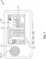
- the IP-based unit 16 can be configured in a housing with a handset 61 in Fig. 8 , and hands free with a speaker/microphone as indicated at 61a and 61b in Fig. 7 .
- the GUI screens 100 in Figs. 7 and 8 each show operational mode selection buttons 102 with the Phone mode button 110 selected and highlighted.
- the IP-based unit 16 determines that a SIP server/IP PBX is available and undergoes registration.
- the IP-based unit 16 is configured (e.g., via software code executed by the microprocessor 92 in the control module 44 ( Fig. 5 )) with a dedicated SIP address. With its IP connectivity and loudspeaker 61a, the unit 16 can enable point-to-point calling and have a "ring" tone generated to the loudspeaker, for example, for point-to-point calls to its dedicated SIP address.
- the unit 16 in this mode of operation provides the ability for the user to make SIP-based IP telephone calls in hands free or handset mode, depending on how the unit is built 16.
- the GUI screen can be programmed and configured to display a telephone keypad 112 for dialing.
- the touch screen display 46 feature of the unit 16 allows for quick-dials, auto-dials and directory lookup by the user (e.g., as indicated at 116 in Fig. 8 ) and provides buttons as necessary for multiple lines, call transfer, and so on as indicated at 114 in Fig. 7 .
- the unit 16 can be configured with an optional camera 48 and then stream the image of the person calling to a receiver unit 16. If both units are camera-capable, the call can be a video call if the units 16 are so configured.
- the IP-based unit 16 is configured in a housing with a handset 61, but could also be hands free with a speaker/microphone as indicated at 61a and 61b in Fig. 7 .
- the GUI screen 100 in Fig. 9 shows operational mode selection buttons 102 with the IPAP (Internet Protocol Access Panel) mode button 118 selected in an access panel mode screen having zone selection buttons 120 for sending announcements to selected zones, alarm buttons 122, and access panel function buttons 124 such as a Cancel ALL button, an Acknowledge ALL button, a Mute ALL button and an Emergency Speech and Routine Speech buttons.
- IPAP Internet Protocol Access Panel
- access panel function buttons 124 such as a Cancel ALL button, an Acknowledge ALL button, a Mute ALL button and an Emergency Speech and Routine Speech buttons.
- an IP unit 16 when operated as a point-to-point intercom, it allows a user to contact another individual on the system via a number.
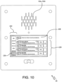
- the GUI screen 100 in each of Figs. 10 and 11 shows operational mode selection buttons 102 with the Point-to-Point mode button 126 selected in a Point-to-Point intercom mode screen. Individual's numbers are provided as respective buttons indicated at 128 which can be scrolled through via the screen 100 on the touch screen display 46.
- Some point-to-point intercom products require specifically configured end-points to be connected to a central server.
- the unit 16 with enhanced point-to-point intercom operation can be configured to mimic existing point-to-point intercom devices by providing a keypad if so desired, but also does not require using a central server since SP2 operations and configuration as described above allow for serverless point-to-point operation.
- specific names indicated generally at 128 such as "Lobby” or "Warehouse” can be used instead of numbers to call a specific person.
- the unit 16 simply rings a VoIP phone of another user upon selection of one of the buttons 128, and the other user will lift the handset or activate hands free mode to communicate.
- Figs. 10 and 11 illustrates examples of different enclosures for the IP unit 16 having no handset 61.
- the call can be a video call if the units 16 are so configured, as illustrated in Fig. 12 .
- These point-to-point intercom operations and functions initiated by activation of respective buttons are performed, for example, in accordance with software code executed by the microprocessor 92 in the control module 44 ( Fig. 5 ).
- Transit system communications such as on-board train communications have specific requirements to allow the crew to communicate with each other or the engineer (e.g., a driver and, in some cases, a driver and a guard for train cars having operators at each end thereof), as well as broadcast announcements to the passengers.
- trains and other single or multiple car transit systems can be provided with a wireless or wired network of IP-based units 16 installed in the car(s).
- a single or multiple car train or other transit system can be provided with a wireless network access point to allow internet service to one or more of IP-based units 16. Fig.
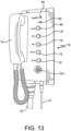
- FIG. 13 depicts an example on-board train communications device 15 having a handset 61, speaker 61, power connection 41, Ethernet connection 17 and plural hardwired, dedicated buttons for calling the driver 72 or the crew 70, or for paging a particular zone 74 or 76 or all zones 80.
- Minimal status information is provided in the form of an LED 84 indicating health of the Ethernet connection 17, or other LED indicator 82 (e.g., to indicate with a call for aid has been initiated by a passenger).
- a call initiated from a crew member to other members of the crew can be established by the unit 16 as hybrid page-party function described above in connection with SP2.
- the VoIP control module 44 is configured, upon receiving inputs from the activation of button 70 for a crew call and depression of the handset 61 pressbar, to direct audio from the caller as a page to crew members in one or more programmed zones and, upon release of the pressbar, to process the audio as party of a party line as described above in connection with an SP2 mode.
- the VoIP control module 44 is configured to respond to a button activation for a call to the driver 72 or a page (e.g., activation of button 74, 76 or 80) using the VoIP technology described above for establishing a point to point call or page.
- On-board communication products often require training on how to use them, and there are several limitations on how calls are queued in each end-point or what information is available to the user regarding the status of incoming calls by other devices. For example, when a user of the on-board unit 15 in Fig. 13 initiates a call to the driver, the user has no indication if an incoming call exists from a crew member.
- the display 46 can provide specific instructions, as well as allow the user to see and select which incoming call is answered.
- Example screens 100 on the display 46 of the unit 16 are provided in Figs. 14 through 22 . Since the unit 16 employs a touch screen 46 programmed with a graphical user interface (GUI) for indicators and input selection buttons, the same hardware and form factor can be used for units 16 having different operations and GUI screens intended for different types of users in accordance with a universal application platform 98 implementing the train communication system. Accordingly, the number of different types of units needed to implement a given communication system is reduced, and the inventory for replacements and repair is therefore also reduced.
- GUI graphical user interface
- a transit communications system having on-board IP-based units 16 can comprise a range of variants as listed in below that are connected together via an Ethernet network to provide audio communication of various types among various railway cars in a railway train, for example.
- the railway train can consist, for example, of a number of passenger cars, at least one passenger or coach car with a guard area, and power cars on either end of the train.
- the below listed variants of the on-board IP-based unit 16 are based on, for example, a common core printed circuit board (PCB) and common firmware (e.g., code executed by the microprocessor 92 in the control module 44 of each on-board unit 16) but are adapted by using different peripherals (e.g., GUI screen features) and electronic configuration (e.g., optional video cameras for point-to-point video conferencing) to produce different desired functionalities as described below in connection with Figs. 14 through 22 and example use cases.
- PCB printed circuit board
- firmware e.g., code executed by the microprocessor 92 in the control module 44 of each on-board unit 16
- peripherals e.g., GUI screen features
- electronic configuration e.g., optional video cameras for point-to-point video conferencing
- IP-based unit 16 provides one or more of plural selected functions using a common form factor such as obviating specialized hardware for various applications, thereby reducing manufacturing costs of the units 16 and simplifying inventory and acquisition of units for a particular system design and maintenance thereof.
- Illustrative variants of on-board IP-based units 16 are:
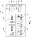
- Fig. 14 depicts a GUI screen 100 on the display 46 providing an overall services screen 140 for a unit 16 configured for on-board communications such as a DGC configured for operation by a crew member of a train car.
- the home GUI screen 140 has a number of outputs or indicators that illuminate, respectively, for indicating, for example, whether the unit is healthy as indicated at 152 (e.g., see illuminated indicator 152 in Fig.
- the unit 16 can also be configured to require other conditions to maintain the illumination of the healthy status indicator 152 and to discontinue activating the indicator 152 when one or more of selected conditions exists such as the unit not being configured, the handset 61 being off hook, while the unit is transmitting a PA announcement, and technical problems with the speaker 61a and/or the microphone 61b and/or the speaker amplifier.
- the home screen 140 for the on-board unit 16 also provides touch screen input buttons 142, 144 and 146, respectively, for selecting a zone for page announcements (e.g., zone 1, zone 2 or all zones), for calling the driver of a train and for calling the crew.
- the microprocessor 92 in the control module 44 is programmed to perform the point-to-point calls or page or party calls as described above, depending on which touch screen input button(s) are activated.
- the on-board unit 16 having a screen 140 as depicted in Fig. 14 is advantageous over the on-board unit 15 in Fig. 13 because the unit 16 can receive an indication from indicator 154 that a call is incoming from the crew, for example, as a user selects the button 144 to call the driver.
- the user can, in turn, terminate the call to the driver.
- the unit 16 can be programmed to give priority order to a hierarchy of call sources (e.g., driver call output in view of crew call input, crew call output in view of an incoming driver call or call from another crew member, and so on).
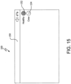
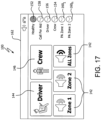
- a driver unit screen 150 (e.g. on an IP-based unit 16 configured as a DGU) can be configured to be simpler than a crew unit screen (e.g., 140) and indicate that the unit 16 is healthy via the illuminated indicator 152 and that the crew is not calling the driver as indicated via the non-illuminated indicator 154.
- a crew unit screen e.g. 140
- the call in progress screen 164 on a driver unit in Fig. 16 if the user is engaged with a call in progress with the driver, and the unit 16 is receiving an incoming call from the crew, the crew indicator 154 is illuminated. Further, instructions 166 can be generated on the screen 100 to guide a user on how to handle the incoming call.
- control module 44 can be programmed to connect calls to the driver from crew members and party line calls from the driver to the crew members, and control the provision of instructions or other information for display on the GUI screens 100 of the different types of units (e.g., driver unit, or crew unit, or passenger unit with call for aid button) depending on the status of the calls in progress.
- the units 16 are each provided with a video camera sensor and lens 48, corresponding units 16 can engage in a videoconference with their respective video images displayed via their corresponding screen displays 46.
- a driver unit 16 (e.g., a DGU-PA) can be provided with a call and page screen 162 having the input touch screen buttons and indicators described above in connection with Fig. 14 .
- the Healthy indicator 152 is illuminated to indicate that the Ethernet connection is good.
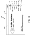
- the corresponding PA Zone 1 indicator e.g., 160 1 is illuminated, as indicated in Fig. 18 .
- the unit 16 can be configured to generate instructions on the screen 182 for generating a page (e.g., "Speak Now. Replace with handset to end the Page.”).
- the UAP 98 can be programmed to provide a number of call processing decisions and pre-programmed instructions for output to the user on the screen 100 of the display 46.
- Fig. 19 illustrates how an on-board train communication unit 16 can be configured to employ its screen 100 on its display device 46 as an exit sign by the generation of an EXIT screen 170 with directional arrows to the nearest exit on the train car.
- the unit 16 can become a public address announcer unit having screen 180 providing options for providing a public address announcement for output by speakers 61a of units 16 in different ones of plural zones or all zones.
- the unit 16 can be a black box of data for analyzing an incident since it can be configured to store status data relating to crew and driver calls and calls for aid.
- units 16 configured to be a public address announcer unit can have GUI interface indicators and buttons for dialing or paging such as buttons 142 for selecting a zone for page announcements (e.g., zone 1, zone 2 or all zones) and indicators for indicating whether a Zone 1 is being paged per indicator 160 1 or whether a Zone n is being paged per indicator 160 n .
- a call initiated from a crew member to other members of the crew can be established by the unit 16 as a hybrid page-party function described above in connection with SP2.
- Touch screen indicators are an improvement to on-board train communication systems that comprise phone units having physical hardwired buttons for dialing and LEDs as indicators.
- the LEDs are limited and merely illuminate when the Ethernet connection to that phone unit is degraded or disconnected and possibly whether a call for aid has been made by a passenger.
- the unit 16 is configured to provide more information to the driver and crew members via the touch screen 46.
- a variety of indicators can be programmed into the UAP 98 of the unit 16 without requiring a hardware change. For example, indicators can illuminate or flash or change colors to convey when a crew call is being received while a user of the unit may be participating in another call.
- the unit 16 indicators can indicate to a user (e.g., a crew member) if a public address message has been generated for a particular zone or all of the zones by another user (e.g., another crew member). A crew member can also be alerted via the indicators if another crew member call is being received while that crew member is engaged in another call with the driver.
- the unit 16 Since the unit 16 is connected via an Ethernet port or interface 14 to an Ethernet network and has a WiFi interface 60 for connecting to other network-enabled devices, the unit can be configured as to operate in an access point mode that provides a local Ethernet connection to the internet for the other devices communicating to the unit 16 via WiFi, for example, or other wireless communication protocol.
- a passenger unit 16 can be provided with buttons configured by the control module 44 to go to a web server to get selected content (e.g., a train schedule, local station maps, local events or hotels).
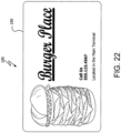
- a passenger unit 16 can be provided with selected content such as advertisements by the control module 44 as indicated in Fig. 22 .
- the wireless interface 60 on a unit 16 allows a passenger smart phone with app to communicate with the unit to call for a train attendant or crew member, which can be useful in a train car where the user does not have access to a unit 16 designed as a Call for Aid unit.
- IP-based units 16 deployed in a transit system e.g., a multiple car railway train
- a transit system e.g., a multiple car railway train
- SP2 page/party and point-to-point call operations described above in a serverless system e.g., a transit system that does not employ a SIP server or for page/party and point-to-point calls among drivers and crew members in the transit system.
- each of the units 16 is assigned an IP address and is operated as a serverless page/party SP2 unit via software executed by the microprocessor 92 in the control module 44 such that the transit system units 16 are configured to be self-aware of each other via the mutual provisioning mode distribution of a system configuration to these units 16 that designates unit IP addresses and multicast addresses of page and party line sockets, as described above in connection with the SP2 operation of an IP-based unit 16 and in accordance with the page zones designated among the units 16 (e.g., based on variant-type or location) and party lines between crew members and driver(s).
- a Driver Unit 16 e.g., DGU
- a driver initiates a call at an IP-based unit 16 configured to operate as a DGU by picking up the handset 61 (e.g.,, if the unit 16 is provided with a handset 61) or by pressing a call button generated via the display 46. All capable crew units 16 (e.g., DGC and DGU-PA) ring and a 'driver' indicator 156 flashes on the screens (e.g., screens 140, 162 and 182) of these crew units.
- the other units stop ringing once the call is connected and the 'driver' indicator 156 is illuminated on all crew units while the call is in progress.
- Call order can be push-to-talk (PTT) on both the transmitting/caller and receiving/called party ends.
- PTT push-to-talk
- a second crew member picks up the handset 61 on a different crew unit during that conversation, then they can press a 'driver' button 144 to join the conversation.
- the call ends when the driver hangs up or less than two participants are active.
- the transit system can be optionally configured to convert the driver call to a crew call. If the driver does not get a response after a selected amount of time (e.g., 10 seconds), the driver unit can be programmed to generate a PA announcement (e.g., "Would a member of the train crew please contact the driver ?").
- a PA announcement e.g., "Would a member of the train crew please contact the driver ?"
- the driver hears the same message in the earpiece of the DGU and can either keep the phone or unit 16 off hook and wait for a crew member to answer (i.e., capable crew units continue to ring/flash until the call is connected), or put the handset 61 down and wait for a crew member to call in, in which case the driver call is cancelled and crew member initiates the call.
- a Crew Unit 16 e.g., DGC, DGU-PA
- Crew units can be configured with prioritization among multiple incoming calls. For example, when the handset 61 of a crew unit 16 is lifted or otherwise taken off-hook, a call from a driver can be prioritized over a call for aid (CFA), which can be prioritized over an incoming call from another crew member.
- CFA call for aid
- the crew member When a crew member initiates a call to the driver from the crew unit 16, the crew member takes the handset off-hook and presses the driver button 144. The driver can, in turn, pick up the handset 61 on the DGU to answer the call. On the other hand, if a second crew member picks up the handset 61 on their corresponding crew unit 16 during this conversation, the second crew member can (a) auto answer the next call in priority queue if the unit 16is ringing (e,g., a 'CFA' indicator 158 or 'crew' indicator 154 is flashed to indicate which call is waiting); (b) press the 'driver' button 144 to join the conversation; (c) press the ⁇ crew' 146 button to make a separate crew to crew call; or (d) press relevant 'PA' buttons 142 to make a PA announcement to one or all zones.
- the call can be PTT format at both ends. The call ends when the driver hangs up or less than two participants are active.
- a crew member When a crew member initiates a call from a first crew unit 16 to a second crew unit 16, the crew member takes the handset off-hook and presses the crew button 146 on the first crew unit 16. All capable crew units (e.g., DGU-PA and DGC) generate a ring and a 'crew' indicator 154 flashes on these units 16. A crew member picks up a handset 16 on another unit 16 to auto answer call. The other crew units 16 stop ringing once the call is connected and the 'crew' indicator 154 is activated (e.g., constant-on) on all these crew units while the call is in progress.
- All capable crew units e.g., DGU-PA and DGC
- All capable crew units generate a ring and a 'crew' indicator 154 flashes on these units 16.
- a crew member picks up a handset 16 on another unit 16 to auto answer call.
- the other crew units 16 stop ringing once the call is connected and the 'crew' indicator
- a third crew member picks up the handset 61 on another unit during that conversation, then they can (a) auto answer the next call in priority queue if the unit 16is ringing (e,g., a 'CFA' indicator 158 or 'driver' indicator 156 is flashed to indicate which call is waiting); (b) press the 'crew' button 146 to join the conversation; (c) press the 'driver' 144 button to make a separate crew to driver call; or (d) press relevant 'PA' buttons 142 to make a PA announcement to one or all zones.
- the call can be PTT format at both ends. The call ends when there are less than two active participants.
- the driver and guard units 16 can be configured with a buzzer or other alarm (e.g., a separate audio component or audio stored in digital memory for playback) that is activated in response to a corresponding buzzer or alarm button generated on the touch screen 46 in accordance with a Right aWay (RW) protocol.
- RW protocol is a manual protocol used between the driver and the guard on a train to ensure that the train is safe to dispatch (e.g., from a platform once all passengers are confirmed to have boarded). Historically, this protocol has entailed a coded sequence of signals using a buzzer.
- the guard buzzes twice to indicate that all passengers have boarded and the doors are closed.
- the driver then buzzes twice to indicate that the guard's buzzer signal has been received.
- the guard then buzzes twice again to confirm. The driver does not start the train moving until the second two buzzes from the guard are heard.
- Some facilities can be designed to allow connection to external devices using I/O, CAN Bus, RS485, WiFi or many other protocols or other analog interfaces such as analog video or audio. These types of installations can take data in or send data out to an external device using a UDP packets sent/received by the unit 16. This configuration allows connection to other devices utilizing the same Ethernet cable as the unit 16, which further reduces installation costs to the end user or end-customer acquiring components to install a IP-based communications system.
- the external device can be wirelessly connected to the unit 16.
- the external user interface port 50 can be used to control an external pan/tilt analog camera for streaming a unit 16's camera video over our Ethernet.
- the units 16 can be deployed for example at different locations in a building and connected to an Ethernet network to provide local nodes or access points.
- Network-enabled devices such as occupancy sensors and environmental sensors can communicate with a unit 16 configured as an access point to the Ethernet network to send data to the cloud, that is, to a remote monitoring system via the internet, for example.
- the units 16 therefore allow for the networked devices to operate in a baseless system, unlike prior building monitoring systems that require all devices to connect to the same local base unit that, in turn, may or may not connect to a remote monitoring system.
- the network-enabled devices can be Internet of Things (IoT) devices, for example, configured for implementing a smart building in terms of sensing environmental and/or occupancy conditions for environment control (e.g., HVAC, motorized window coverings) and/or security purposes.
- IoT Internet of Things
- the building need not have WiFi connectivity throughout, which can be difficult to achieve in some building structures, since placement of a number of the units 16 within range of these network-enabled devices as local nodes provides WiFi connectivity and internet access.
- the unit 16 can be configured to receive via the Ethernet network and Ethernet interface 14 commands (e.g., to control a device such as a thermostat for HVAC, or a camera or door lock for a security system) for transmission to the network-enabled devices via the WiFi interface 60.
- a unit 16 can be provided at a locked entrance to the building and programmed to operate in a point-to-point communication mode ( Figs. 10 and 11 ) or in a point-to-point video call mode ( Fig. 12 ) with a unit 16 provided at a security guard station in the building.
- the unit 16 can have a simple screen with only one button to press to initial the call to the security desk unit 16.
- the visitor unit can be preconfigured by its control module 44 to hot dial the security unit upon removal of a handset from its cradle on the visitor unit.
- the point to point call between a visitor and a security guard can result in the guard using his unit 16 to generate a signal via the WiFi interface 16 to remotely unlock a network-enabled lock on a door and permit the visitor to enter the building.
- the guard unit 16 can also be programmed with buttons for dialing the units 16 of respective various tenants or other personnel in the building to announce the arrival of the visitor.
- the units 16 can be implemented in the form factor of desktop phones connected to a building's Ethernet network and have local alarm functionality that obviates installation of separate public address/speaker system in building.
- the units 16 can be configured to operate as a public address and alarm (PAA) system that can communicate audible alarms and pages via the speaker 61 on the unit 16.
- PAA public address and alarm
- the units 16 can also be provided with alarm or announcement-related messages (e.g., "This alarm is only a test") in a GUI screen 100 generated on the touch screen display 46.
- the units 16 can be configured to allow a user to receive and provide audio via a Bluetooth-enabled headset paired with the wireless interface 60.
- the units 16 can be configured to allow a user to download contacts from their smartphone to the unit 16 via the wireless interface 60.
- mode selection buttons 102 can include fewer or more mode buttons than the 4 mode buttons 104, 110, 118 and 126 described above, as well as relate to different operational modes than the modes indicated in Figs. 6-12 , or the different user modes in connection with the on-board communication units described in connection with Figs. 14-22 .
- the VoIP units 15 and 16 are fully functional SIP VoIP phones.
- the VoIP units 16 described herein operate in various modes that can be remotely configured such as by providing commands or updated software instructions via one of the interfaces described above in connection with Fig.5 (e.g., WiFi 60 or external user interface port 50).
- Configurable, multi-function IP-based Units 16 with touch screen displays in accordance with example embodiments of the present invention are advantageous in that one form factor is operable as a number of devices having different functions for versatility and simplicity in communication system installations.
- a touch screen display By the addition of a touch screen display, the abilities of a serverless station or unit 16, for example, become much more broad in that, not only can the unit 16 be used as a more capable page/party station, but the unit 16 can also be used as a VoIP telephone (i.e., where a SIP server is required), an access panel for activating alarms on a PA/GA system, a point-to-point (e.g., serverless) intercom, or a video capture device to stream video from the station's perspective to a central video switch/controller.
- adding hands free capabilities further enhances the unit 16 in various applications.
- the components of the illustrative devices, systems and methods employed in accordance with the illustrative embodiments of the present invention can be implemented, at least in part, in digital electronic circuitry, analog electronic circuitry, or in computer hardware, firmware, software, or in combinations of them. These components can be implemented, for example, as a computer program product such as a computer program, program code or computer instructions tangibly embodied in an information carrier, or in a machine-readable storage device, for execution by, or to control the operation of, data processing apparatus such as a programmable processor, a computer, or multiple computers.
- a computer program product such as a computer program, program code or computer instructions tangibly embodied in an information carrier, or in a machine-readable storage device, for execution by, or to control the operation of, data processing apparatus such as a programmable processor, a computer, or multiple computers.
- a computer program can be written in any form of programming language, including compiled or interpreted languages, and it can be deployed in any form, including as a stand-alone program or as a module, component, subroutine, or other unit suitable for use in a computing environment.
- a computer program can be deployed to be executed on one computer or on multiple computers at one site or distributed across multiple sites and interconnected by a communication network.
- functional programs, codes, and code segments for accomplishing illustrative embodiments of the present invention can be easily construed as within the scope of the invention by programmers skilled in the art to which the present invention pertains.
- Method steps associated with the illustrative embodiments of the present invention can be performed by one or more programmable processors executing a computer program, code or instructions to perform functions (e.g., by operating on input data and/or generating an output). Method steps can also be performed by, and apparatus of the illustrative embodiments can be implemented as, special purpose logic circuitry, e.g., an FPGA (field programmable gate array) or an ASIC (application-specific integrated circuit).
- FPGA field programmable gate array
- ASIC application-specific integrated circuit
- processors suitable for the execution of a computer program include, by way of example, both general and special purpose microprocessors, and any one or more processors of any kind of digital computer.
- a processor will receive instructions and data from a read-only memory or a random access memory or both.
- the essential elements of a computer are a processor for executing instructions and one or more memory devices for storing instructions and data.
- a computer will also include, or be operatively coupled to receive data from or transfer data to, or both, one or more mass storage devices for storing data, e.g., magnetic, magneto-optical disks, or optical disks.
- Information carriers suitable for embodying computer program instructions and data include all forms of non-volatile memory, including by way of example, semiconductor memory devices, e.g., EPROM, EEPROM, and flash memory devices; magnetic disks, e.g., internal hard disks or removable disks; magneto-optical disks; and CD-ROM and DVD-ROM disks.
- semiconductor memory devices e.g., EPROM, EEPROM, and flash memory devices
- magnetic disks e.g., internal hard disks or removable disks
- magneto-optical disks e.g., CD-ROM and DVD-ROM disks.
- the processor and the memory can be supplemented by, or incorporated in special purpose logic circuitry.
- DSP Digital Signal Processor
- SOC system on chip
- ASIC Application Specific Integrated Circuit
- FPGA Field Programmable Gate Array
- a general purpose processor may be a microprocessor, but in the alternative, the processor may be any conventional processor, controller, microcontroller, or state machine.
- a processor may also be implemented as a combination of computing devices, e.g., a combination of a DSP and a microprocessor, a plurality of microprocessors, one or more microprocessors in conjunction with a DSP core, or any other such configuration.
- a software module may reside in Random Access Memory (RAM), flash memory, Read Only Memory (ROM), Electrically Programmable ROM (EPROM), Electrically Erasable Programmable ROM (EEPROM), registers, hard disk, a removable disk, a CD-ROM, or any other form of storage medium known in the art.
- An exemplary storage medium is coupled to the processor such the processor can read information from, and write information to, the storage medium.
- the storage medium may be integral to the processor.
- the processor and the storage medium may reside in an ASIC.
- the ASIC may reside in the remote station, Electronic medical device, a server, or a combination thereof.
- the processor and the storage medium may reside as discrete components in a user terminal.
Landscapes
- Engineering & Computer Science (AREA)
- Theoretical Computer Science (AREA)
- General Engineering & Computer Science (AREA)
- Signal Processing (AREA)
- Human Computer Interaction (AREA)
- General Physics & Mathematics (AREA)
- Physics & Mathematics (AREA)
- Business, Economics & Management (AREA)
- General Business, Economics & Management (AREA)
- Multimedia (AREA)
- Computer Networks & Wireless Communication (AREA)
- Telephonic Communication Services (AREA)
- Telephone Function (AREA)
- Interconnected Communication Systems, Intercoms, And Interphones (AREA)
Claims (17)
- Konfigurierbare, multifunktionelle Voice over Internet Protocol verwendende Einheit (VoIP-Einheit) (16), die Folgendes umfasst:ein VoIP-Steuermodul (44) zum Steuern von VolP-Vorgängen der VoIP-Einheit (16) hinsichtlich anderer VolP-Einheiten in einem Internet Protocol-Netzwerk (IP-Netzwerk), wobei das VoIP-Steuermodul (44) dazu konfiguriert ist, die VoIP-Einheit (16) in einer Vielzahl von Modi arbeiten zu lassen, indem sie selektiv an mindestens einer Kommunikation aus einer Punkt-Zu-Punkt-Kommunikation zwischen der VoIP-Einheit (16) und einer anderen der VolP-Einheiten in dem IP-Netzwerk und einer Multicast-Kommunikation zwischen der VolP-Einheit (16) und einer Vielzahl der VoIP-Einheiten teilnimmt, je nachdem, in welchem Modus der Vielzahl von Modi die VoIP-Einheit (16) gerade arbeitet, wobei die Vielzahl von Modi mindestens zwei Modi aus einem serverlosen Meldungsempfangs-Teilnehmerempfangs-(SP2)-Stationsmodus, einem Zugriffspanel-Modus, der über ein IP-Netzwerk eine Alarmaktivierung und Notfall-Ansage-Rundsendung in ausgewählte Zonen bereitstellt, und einen serverlosen Punkt-Zu-Punkt-Interkom-Modus umfassen;einen Lautsprecher (61a), der mit dem VoIP-Steuermodul (44) gekoppelt und zur Audioausgabe konfiguriert ist;ein Mikrofon (61b), das mit dem VoIP-Steuermodul (44) gekoppelt und zum Empfangen einer Audioeingabe konfiguriert ist;eine Berührungsbildschirmanzeige (46), die mit dem VoIP-Steuermodul (44) gekoppelt und dazu konfiguriert ist, eine grafische Benutzerschnittfläche so arbeiten zu lassen, dass sie die dem aktuell aus der Vielzahl von Modi ausgewählten Modus entsprechende Anzeigeoberfläche (20, 100) erzeugt und über die Anzeigeoberflächen (20, 100) Benutzereingaben empfängt, wobei mindestens eine der Anzeigeoberflächen (20, 100) Arbeitsmodusauswahltasten (102, 104, 110, 118, 126) umfasst, die jeweiligen Modi aus der Vielzahl von Modi entsprechen, wobei das VoIP-Steuermodul (44) dazu konfiguriert ist, auf die Aktivierung einer der Arbeitsmodusauswahltasten (102, 104, 110, 118, 126) zu reagieren, indem es die VolP-Einheit (16) gemäß dem entsprechenden Modus aus der Vielzahl von Modi arbeiten lässt; undein IP-Netzwerk-Schnittstellenmodul (42), das mit dem VoIP-Steuermodul (44) und dem IP-Netzwerk verbunden ist und dazu konfiguriert ist, bidirektionale Ethernet-Daten zwischen dem IP-Netzwerk und dem VoIP-Steuermodul (44) auszutauschen und über das IP-Netzwerk empfangene Audiosignale für die Ausgabe über den Lautsprecher (61a) aufzubereiten und über das Mikrofon (61b) eingegebene Audiosignale für die Übertragung über das IP-Netzwerk aufzubereiten.
- Konfigurierbare multifunktionelle VoIP-Einheit nach Anspruch 1, wobei die Berührungsbildschirmanzeige (46) ein Bildschirmpanel aus einem stoßfesten Material umfasst; und/oder wobei die Berührungsbildschirmanzeige (46) einen Berührungsbildschirm umfasst, der optisch mit einer Flüssigkristallanzeige gebondet ist, wobei durch das optische Bonding ein etwaiger Luftspalt zwischen dem Berührungsbildschirm und der Flüssigkristallanzeige entfernt wird; und/oder
wobei die VoIP-Einheit (16) ferner ein robustes Gehäuse umfasst, an das die Berührungsbildschirmanzeige (46) an einer Außenfläche davon angebracht ist und das gemäß der Klassifizierung Class 1, Division 2 der Publication 70, National Electric Code® (NEC) der National Fire Protection Association (NFPA) konfiguriert ist. - Konfigurierbare multifunktionelle VolP-Einheit nach Anspruch 1, die ferner einen Videokamerasensor und eine Linse (48) umfasst, wobei das VoIP-Steuermodul (44) dazu konfiguriert ist, Videoanrufdaten von dem Videokamerasensor und der Linse (48) an mindestens eine der VoIP-Einheiten in dem IP-Netzwerk zu senden und Videoanrufdaten von der mindestens einen der VoIP-Einheiten, die ebenfalls einen Videokamerasensor und eine Linse umfasst, zu empfangen.
- Konfigurierbare multifunktionelle VolP-Einheit nach Anspruch 1, wobei die Berührungsbildschirmanzeige (46) dazu konfiguriert ist, wenn die VoIP-Einheit (16) so konfiguriert ist, dass sie im VolP-Telefonmodus arbeitet, mindestens eine grafische Benutzeranzeigeoberfläche (20, 100) zu erzeugen, die mindestens eine Eingabetaste bereitstellt, die aus der Gruppe Telefontastatur mit nummerierten Tasten (112) zum Vornehmen von Tastenwahlblocktelefonanrufen, mindestens eine Taste (114) zum Vornehmen eines automatisch gewählten Anrufs, Telefonbuchnachschlagetabelle, aus der der Benutzer einen aufgelisteten Anrufempfänger auswählen und automatisch anwählen kann, Taste zum Vornehmen eines Anrufs über mehrere Leitungen und Taste zum Weiterleiten von Anrufen ausgewählt ist, wobei das VolP-Steuermodul (44) dazu konfiguriert ist, in Abhängigkeit von der Aktivierung der mindestens einen Eingabetaste mindestens eine Kommunikation aus der Punkt-Zu-Punkt-Kommunikation und der Multicast-Kommunikation mit mindestens einer der anderen VoIP-Einheiten herzustellen.
- Konfigurierbare multifunktionelle VoIP-Einheit nach Anspruch 1, wobei die Berührungsbildschirmanzeige (46) dazu konfiguriert ist, wenn die VoIP-Einheit (16) so konfiguriert ist, dass sie im SP2-Modus arbeitet, mindestens eine grafische Benutzeranzeigeoberfläche (20, 100) zu erzeugen, die mindestens eine Eingabetaste bereitstellt, die aus der Gruppe Tasten (106), die einer jeweiligen Leitung aus einer Vielzahl von Teilnehmerempfangsleitungen entsprechen, und Tasten (108) zum Auswählen mindestens eines Meldungsempfangsziels, wobei die Meldungsempfangszieltasten (108) mit mindestens einem aus einer Zonennummer und einer alphanumerischen Zielbezeichnung beschriftet sind, ausgewählt ist, wobei das VolP-Steuermodul (44) dazu konfiguriert ist, in Abhängigkeit von der Aktivierung der mindestens einen Eingabetaste mindestens eine Kommunikation aus der Punkt-Zu-Punkt-Kommunikation und der Multicast-Kommunikation mit entsprechenden der anderen VoIP-Einheiten herzustellen.
- Konfigurierbare multifunktionelle VolP-Einheit nach Anspruch 1, wobei die Berührungsbildschirmanzeige (46) dazu konfiguriert ist, wenn die VoIP-Einheit (16) so konfiguriert ist, dass sie im Zugriffspanel-Modus arbeitet, mindestens eine grafische Benutzeranzeigeoberfläche (20, 100) zu erzeugen, die mindestens eine Eingabetaste bereitstellt, die aus der Gruppe Tasten (120), die verschiedenen Zonen entsprechen, zum Auswählen des Empfangs einer Rundsendungs- oder Interkom-Nachricht, Tasten (122), die jeweiligen verschiedenen Alarmarten entsprechen, und Zugriffspanelsteuerungstasten (124) für mindestens eines aus Alarmabbruch, Bestätigung, Stummschaltung und Sprachart, ausgewählt ist, wobei das VolP-Steuermodul (44) dazu konfiguriert ist, in Abhängigkeit von der Aktivierung der mindestens einen Eingabetaste mindestens eine Kommunikation aus der Punkt-Zu-Punkt-Kommunikation und der Multicast-Kommunikation mit entsprechenden der anderen VoIP-Einheiten herzustellen.
- Konfigurierbare multifunktionelle VolP-Einheit nach Anspruch 1, wobei die Berührungsbildschirmanzeige (46) dazu konfiguriert ist, wenn die VolP-Einheit (16) so konfiguriert ist, dass sie in dem serverlosen Punkt-Zu-Punkt-Interkom-Modus arbeitet, mindestens eine grafische Benutzeranzeigeoberfläche (20, 100) zu erzeugen, die eine Telefonbuchnachschlagetabelle (128) bereitstellt, aus der der Benutzer einen aufgelisteten Anrufempfänger auswählen und anwählen kann, wobei das VoIP-Steuermodul (44) dazu konfiguriert ist, in Abhängigkeit von der Aktivierung jeweiliger Anrufempfängertasten in der Telefonbuchnachschlagetabelle die Punkt-Zu-Punkt-Kommunikation mit entsprechenden der anderen VoIP-Einheiten herzustellen.
- Konfigurierbare multifunktionelle VoIP-Einheit nach Anspruch 1, wobei das VoIP-Steuermodul (44) so konfiguriert ist, dass es die VolP-Einheit (16) in einem ÖVP-System-Kommunikationsmodus arbeiten lässt, der aus der Gruppe Fahrerkommunikationsmodus zum Herstellen von Anrufen von einem Fahrer mit Mitgliedern des Fahrpersonals, Fahrpersonalkommunikationsmodus zum Herstellen von Anrufen von mindestens einem Mitglied des Fahrpersonals mit dem Fahrer oder einem anderen Mitglied des Fahrpersonals, Fahrgastkommunikationsmodus zum Herstellen von Anrufen von einem Fahrgast mit mindestens einem Mitglied des Fahrpersonal und einem Ansage-Modus zum Übertragen einer Bekanntmachung an die anderen VoIP-Einheiten ausgewählt ist.
- Konfigurierbare multifunktionelle VolP-Einheit nach Anspruch 8, die ferner einem Hörer (61) mit dem Lautsprecher (61a) und dem Mikrofon (61b) und eine Gabel umfasst, die dazu konfiguriert ist, einen Schalter zu betätigen, der, wenn der Hörer (61) von der Gabel genommen wird, ein Signal an das VoIP-Steuermodul (44) erzeugt, wenn die VolP-Einheit (16) so konfiguriert ist, dass sie im Fahrerkommunikationsmodus arbeitet, mindestens eines aus einem Meldungsempfangs- und einem Teilnehmerempfangsanruf an mindestens eine der von einem Mitglied des Fahrpersonals bedienten VoIP-Einheiten einzuleiten; und/oder
wobei die Berührungsbildschirmanzeige (46) dazu konfiguriert ist, mindestens eine grafische Benutzeranzeigeoberfläche (20, 100) zu erzeugen, die eine Auswahltaste bereitstellt, um, wenn die VoIP-Einheit (16) so konfiguriert ist, dass sie im Fahrerkommunikationsmodus arbeitet, als Reaktion auf die Aktivierung der Auswahltaste einen Anruf an mindestens eine der von einem Mitglied des Fahrpersonals bedienten VoIP-Einheiten einzuleiten. - Konfigurierbare, multifunktionelle VoIP-Einheit nach Anspruch 8, wobei das VolP-Steuermodul (44), wenn das VoIP-Steuermodul (44) so konfiguriert ist, dass es im ÖVP-System-Kommunikationsmodus arbeitet, über den SP2-Stationsmodus derart arbeitet, dass es jeweils von dem Fahrer und Mitgliedern des Fahrpersonals bediente VoIP-Einheiten verbindet, indem es unter der VoIP-Einheit (16) und den anderen VolP-Einheiten eine Systemkonfiguration verteilt, durch die der VoIP-Einheit (16) und den anderen VoIP-Einheiten jeweils IP-Adressen zugeteilt werden und Multicast-Adressen von Meldungsempfangs- und Teilnehmerempfangsleitungsbuchsen zuteilt, die von der VoIP-Einheit (16) in Bezug auf die anderen VoIP-Einheiten verwendet werden, um an Teilnehmerempfangsanrufen zwischen dem Fahrer und den Mitgliedern des Fahrpersonals teilzunehmen und über die VoIP-Einheiten Bekanntmachungen über den Meldeempfang bereitzustellen; und/oder
wobei, wenn die VoIP-Einheit (16) gemäß dem SP2-Stationsmodus konfiguriert ist, die VoIP-Steuereinheit (16) so konfiguriert ist, dass sie selbst Kenntnis über die andere VoIP-Einheiten erlangt, indem sie einen gemeinsamen Kanal zum Senden oder Empfangen der Systemkonfiguration verwendet. - Konfigurierbare, multifunktionelle VoIP-Einheit nach Anspruch 8, wobei, wenn die VoIP-Einheit (16) so konfiguriert ist, dass sie im Fahrpersonalkommunikationsmodus arbeitet, die Berührungsbildschirmanzeige (46) dazu konfiguriert ist,mindestens eine grafische Benutzeranzeigeoberfläche (20, 100) zu erzeugen, die mindestens eine Eingabetaste bereitstellt, die aus der Gruppe Fahrerruftaste (144), Fahrpersonalruftaste (146), mindestens eine Meldungsempfangszonentaste (142) und Taste zum Meldungsempfang in allen Zonen (142) ausgewählt ist, wobei das VolP-Steuermodul (44) dazu konfiguriert ist, in Abhängigkeit von der Aktivierung der mindestens einen Eingabetaste mindestens eine Kommunikation aus der Punkt-Zu-Punkt-Kommunikation und der Multicast-Kommunikation mit entsprechenden der anderen VoIP-Einheiten herzustellen; und/odereinen Hinweisgeber zu erzeugen, der anzeigt, dass die VoIP-Einheit (16) eine Verbindung zu dem IP-Netzwerk (152) hat und wenn ein eingehender Anruf von mindestens einem von dem Fahrer (156) und einem anderen Mitglied des Fahrpersonals (156) empfangen, eine Hilferuftaste bei einer der VolP-Einheiten (158) aktiviert und ein bei einer der VoIP-Einheiten (1601, 160n) ein Meldungsempfang hergestellt wird.
- Konfigurierbare, multifunktionelle VolP-Einheit nach Anspruch 8, wobei, wenn die VolP-Einheit (16) so konfiguriert ist, dass sie im Fahrerkommunikationsmodus arbeitet, die Berührungsbildschirmanzeige (46) dazu konfiguriert ist,mindestens einen grafischen Benutzeranzeigeoberfläche (20, 100) zu erzeugen, die anzeigt, dass die VoIP-Einheit (16) einen Fahreranruf mit den von Mitgliedern des Fahrpersonals bedienten VoIP-Einheiten hergestellt hat, und mindestens einen Hinweisgeber (154) zu erzeugen, der anzeigt, dass die VoIP-Einheit (16) einen von einer der von einem Mitglied des Fahrpersonals bedienten VoIP-Einheiten eingehenden Anruf hat, und dass mindestens ein Eingabebildschirmbereich aktiviert wird, um den während des Fahreranrufs eingehenden Anruf anzunehmen; und/odermindestens einen Hinweisgeber zu erzeugen, der aus der Gruppe Hinweisgeber (152), der anzeigt, dass die VoIP-Einheit (16) eine Verbindung zu dem IP-Netzwerk hat, und Hinweisgeber, der anzeigt, dass ein eingehender Anruf von einer der von einem Mitglied des Fahrpersonals bedienten VoIP-Einheiten empfangen wird, ausgewählt ist.
- Konfigurierbare multifunktionelle VolP-Einheit nach Anspruch 8, wobei die Berührungsbildschirmanzeige (46) dazu konfiguriert ist, wenn die VoIP-Einheit (16) so konfiguriert ist, dass sie im Ansage-Modus arbeitet, mindestens eine grafische Benutzeranzeigeoberfläche (20, 100) zu erzeugen, die anzeigt, wenn eine Meldungsempfangsadresse erzeugt wird; und/oder die Berührungsbildschirmanzeige (46) dazu konfiguriert ist, wenn die VoIP-Einheit (16) so konfiguriert ist, dass sie im Fahrpersonalkommunikationsmodus arbeitet, mindestens einen Hinweisgeber zu erzeugen, der anzeigt, dass die VolP-Einheit (16) eine Verbindung zu dem IP-Netzwerk (152) hat und dass ein eingehender Anruf von mindestens einem von dem Fahrer (156) und einem anderen Mitglied des Fahrpersonals (154) empfangen, eine Hilferuftaste auf einer der VolP-Einheiten (158) aktiviert und ein auf einer der VoIP-Einheiten (1601, 160n) ein Meldungsempfang hergestellt wird.
- Konfigurierbare multifunktionelle VoIP-Einheit nach Anspruch 8, wobei die Berührungsbildschirmanzeige (46) dazu konfiguriert ist, wenn die VolP-Einheit (16) so konfiguriert ist, dass sie im Fahrgastkommunikationsmodus arbeitet, mindestens eine grafischen Benutzeranzeigeoberfläche (20, 100) zu erzeugen, die mindestens eines von einer Werbung und einem Ausgangszeichen (170) mit mindestens einem von alphanumerischen Zeichen und Richtungspfeilen anzeigt, die sich auf einen Ausgang aus dem ÖVP-System beziehen.
- Konfigurierbare multifunktionelle VoIP-Einheit nach Anspruch 8, wobei, wenn die VoIP-Einheit (16) mit einem drahtlosen Kommunikationszugangspunkt verbunden ist, die Berührungsbildschirmanzeige (46) dazu konfiguriert ist, über das Internet empfangene Informationen anzuzeigen.
- Konfigurierbare, multifunktionelle VoIP-Einheit nach Anspruch 1, wobei die Vielzahl von Modi ferner einen Modus für Anrufe über eine Teilnehmerempfangsleitung und einen Videoanrufmodus umfasst.
- Konfigurierbare, multifunktionelle VoIP-Einheit nach Anspruch 1, wobei jeder der Anzeigeoberflächen die Arbeitsmodusauswahltasten (102, 104, 110, 118, 126) und mindestens eine Eingabetaste umfasst, die dem ausgewählten Modus aus der Vielzahl der Modi entspricht, die über die aktivierte Arbeitsmodusauswahltaste (102, 104, 110, 118, 126) ausgewählt werden, entspricht.
Applications Claiming Priority (3)
| Application Number | Priority Date | Filing Date | Title |
|---|---|---|---|
| US201762546864P | 2017-08-17 | 2017-08-17 | |
| US201762581247P | 2017-11-03 | 2017-11-03 | |
| PCT/US2018/000221 WO2019035948A1 (en) | 2017-08-17 | 2018-08-16 | ENHANCED, MULTIFUNCTION, CONFIGURABLE VOIP COMMUNICATION DEVICE WITH UNIVERSAL APPLICATION PLATFORM |
Publications (3)
| Publication Number | Publication Date |
|---|---|
| EP3669518A1 EP3669518A1 (de) | 2020-06-24 |
| EP3669518A4 EP3669518A4 (de) | 2021-05-12 |
| EP3669518B1 true EP3669518B1 (de) | 2023-10-04 |
Family
ID=65361225
Family Applications (1)
| Application Number | Title | Priority Date | Filing Date |
|---|---|---|---|
| EP18846113.1A Active EP3669518B1 (de) | 2017-08-17 | 2018-08-16 | Konfigurierbare multifunktionelle robuste voice-over-internetprotokoll (voip)-kommunikationsvorrichtung mit universeller anwendungsplattform |
Country Status (7)
| Country | Link |
|---|---|
| US (2) | US10873658B2 (de) |
| EP (1) | EP3669518B1 (de) |
| CN (1) | CN111133730B (de) |
| CA (1) | CA3072462A1 (de) |
| CL (1) | CL2020000391A1 (de) |
| MX (1) | MX2020001674A (de) |
| WO (1) | WO2019035948A1 (de) |
Families Citing this family (12)
| Publication number | Priority date | Publication date | Assignee | Title |
|---|---|---|---|---|
| KR102419374B1 (ko) * | 2017-07-21 | 2022-07-11 | 삼성전자주식회사 | 사용자 발화를 처리하는 전자 장치 및 그 전자 장치의 제어 방법 |
| WO2019222351A1 (en) | 2018-05-15 | 2019-11-21 | Hubbell Incorporated | Access control systems and methods for multi-unit premises |
| CN119835257A (zh) | 2018-06-20 | 2025-04-15 | 哈贝尔公司 | 经由互联网在不同lan中的voip设备之间路由多播寻呼/对讲呼叫音频的系统 |
| EP4343534B1 (de) * | 2018-08-23 | 2026-01-14 | Google Llc | Regelung des ansprechverhaltens eines assistenten je nach den eigenschaften einer multiassistent-umgebung |
| US10762893B2 (en) | 2018-09-28 | 2020-09-01 | Comcast Cable Communications, Llc | Monitoring of one or more audio/video collection devices |
| WO2021247400A1 (en) | 2020-06-03 | 2021-12-09 | Hubbell Incorporated | Internet protocol (ip)-speaker with ip-camera |
| US12439135B2 (en) * | 2021-01-11 | 2025-10-07 | Action-CS | Camera adaptor |
| CN113938637A (zh) * | 2021-09-13 | 2022-01-14 | 广州市迪士普音响科技有限公司 | 一种无服务器可视对讲寻呼系统及其实现方法 |
| EP4409865B1 (de) * | 2021-09-30 | 2026-01-21 | ALSTOM Holdings | Verfahren und system für besatzungspassagierkommunikation |
| US12093293B2 (en) * | 2022-02-28 | 2024-09-17 | International Business Machines Corporation | Synchronizing a sensor network and an ontology |
| CN121844555A (zh) * | 2023-09-14 | 2026-04-10 | 罗伯特·博世有限公司 | 内部通信管理系统 |
| US12579361B1 (en) * | 2025-08-25 | 2026-03-17 | Isotopes AI, Inc. | Collaborative data analytics using machine learning based language models |
Citations (1)
| Publication number | Priority date | Publication date | Assignee | Title |
|---|---|---|---|---|
| WO2009128616A9 (ko) * | 2008-04-17 | 2010-03-04 | Kim Hwang-Hyun | 인터넷 프로토콜 비디오폰 및 광고제공 시스템 |
Family Cites Families (15)
| Publication number | Priority date | Publication date | Assignee | Title |
|---|---|---|---|---|
| US20030058806A1 (en) | 2001-09-24 | 2003-03-27 | Teleware, Inc. | Multi-media communication system with advanced conference call management |
| US7599355B2 (en) * | 2003-08-14 | 2009-10-06 | Aksys Networks Inc. | Server-less VoIP (voice over internet protocol) phone system |
| CN101433035A (zh) * | 2004-09-08 | 2009-05-13 | 克莫卡公司 | 用于操作因特网协议(ip)电话上的数据语音应用的软件平台 |
| US7277018B2 (en) * | 2004-09-17 | 2007-10-02 | Incident Alert Systems, Llc | Computer-enabled, networked, facility emergency notification, management and alarm system |
| US8296837B2 (en) * | 2005-03-18 | 2012-10-23 | Barclays Capital Inc. | VoIP proxy server |
| US8345663B2 (en) * | 2007-03-23 | 2013-01-01 | Thales Avionics, Inc. | Distributed cabin interphone system for a vehicle |
| US9369294B2 (en) * | 2007-12-14 | 2016-06-14 | Telecommunication Systems, Inc. | Reverse 911 using multicast session internet protocol (SIP) conferencing of voice over internet protocol (VoIP) users |
| US8577385B2 (en) * | 2010-12-31 | 2013-11-05 | Motorola Solutions, Inc. | Method and system for delivering media to a plurality of mobile devices in a cell with a group transport function |
| US20140297418A1 (en) | 2013-03-28 | 2014-10-02 | Vivek GAUR | Deliver passenger centric advertisements to in-flight entertainment system using auction based exchange |
| US9716965B2 (en) * | 2013-04-27 | 2017-07-25 | Lg Electronics Inc. | Mobile terminal and controlling method thereof |
| WO2015031624A1 (en) | 2013-08-30 | 2015-03-05 | Hubbell Incorporated | Wifi hazardous area voip paging telephone and system |
| WO2015172006A1 (en) | 2014-05-08 | 2015-11-12 | Ubiquiti Networks, Inc. | Phone systems and methods of communication |
| EP3235230B1 (de) | 2014-12-19 | 2020-07-08 | Hubbell Incorporated | Station für serverless-page-party (spp) über internetptotokoll (ip) und systeme und verfahren zur verwendung mehrerer spp-stationen |
| CN105991856B (zh) * | 2015-03-05 | 2021-01-12 | 李明 | 基于rtp服务器到服务器寻路由的voip寻路由 |
| US10409439B2 (en) | 2015-08-05 | 2019-09-10 | Samsung Electronics Co., Ltd. | User terminal apparatus and controlling method thereof |
-
2018
- 2018-08-16 EP EP18846113.1A patent/EP3669518B1/de active Active
- 2018-08-16 CN CN201880061963.9A patent/CN111133730B/zh active Active
- 2018-08-16 MX MX2020001674A patent/MX2020001674A/es unknown
- 2018-08-16 US US15/998,513 patent/US10873658B2/en active Active
- 2018-08-16 WO PCT/US2018/000221 patent/WO2019035948A1/en not_active Ceased
- 2018-08-16 CA CA3072462A patent/CA3072462A1/en active Pending
-
2020
- 2020-02-17 CL CL2020000391A patent/CL2020000391A1/es unknown
- 2020-11-24 US US17/103,580 patent/US11356544B2/en active Active
Patent Citations (1)
| Publication number | Priority date | Publication date | Assignee | Title |
|---|---|---|---|---|
| WO2009128616A9 (ko) * | 2008-04-17 | 2010-03-04 | Kim Hwang-Hyun | 인터넷 프로토콜 비디오폰 및 광고제공 시스템 |
Also Published As
| Publication number | Publication date |
|---|---|
| MX2020001674A (es) | 2020-07-13 |
| CN111133730A (zh) | 2020-05-08 |
| US20210075899A1 (en) | 2021-03-11 |
| CN111133730B (zh) | 2022-06-28 |
| US11356544B2 (en) | 2022-06-07 |
| US10873658B2 (en) | 2020-12-22 |
| EP3669518A4 (de) | 2021-05-12 |
| CA3072462A1 (en) | 2019-02-21 |
| CL2020000391A1 (es) | 2020-11-13 |
| US20190058783A1 (en) | 2019-02-21 |
| WO2019035948A1 (en) | 2019-02-21 |
| EP3669518A1 (de) | 2020-06-24 |
Similar Documents
| Publication | Publication Date | Title |
|---|---|---|
| US11356544B2 (en) | Configurable multi-function ruggedized voice over internet protocol (VoIP) communications device with universal application platform | |
| UA76998C2 (uk) | Спосіб та пристрій з'єднання по інтермережі системи моніторів внутрішнього відеотелефонного зв'язку з терміналом консьєржа | |
| EP3811599B1 (de) | System zur weiterleitung von multicast-seiten-/teilnehmeranruf-audio zwischen voip-vorrichtungen in verschiedenen lans über das internet | |
| US10807831B2 (en) | Elevator system | |
| JP2007096770A (ja) | インターホンシステム | |
| RU2405701C1 (ru) | Система интегрированной цифроаналоговой железнодорожной радиосвязи | |
| JP2007274177A (ja) | インターホンシステム | |
| US11159592B2 (en) | Systems, apparatuses and methods for party line calls among voice over internet protocol (VoIP) telephones | |
| JP2007124139A (ja) | 集合住宅のインターホン電話呼出通話連携システム | |
| JP2009135680A (ja) | インターホンシステム | |
| JP2007235220A (ja) | 集合住宅インターホンシステム | |
| JP4007328B2 (ja) | 集合住宅用監視・通話システム | |
| JP5291288B2 (ja) | インターホンシステム | |
| US20190289133A1 (en) | Building controller and interphone system | |
| JP2007049583A (ja) | ナースコールシステム | |
| JP2005260359A (ja) | 集合住宅用監視・通話システム | |
| EP3367652B1 (de) | Verteiler, türtelefonsystem und kommunikationsverfahren | |
| JP2008135885A (ja) | インターホンシステム | |
| JP2008024428A (ja) | ビル遠隔監視装置 | |
| EP3367653B1 (de) | Empfangsbereichsgegensprechanlage, türgegensprechanlage und kommunikationsverfahren | |
| RU2391793C1 (ru) | Способ двухсторонней парковой связи с цифровой коммутацией | |
| JP2010245643A (ja) | インターホン/携帯電話複合システム | |
| JP2005117470A (ja) | 集合住宅インターホンシステム | |
| JP6666742B2 (ja) | 通信装置および通信方法 | |
| JP2007174414A (ja) | 機能装置 |
Legal Events
| Date | Code | Title | Description |
|---|---|---|---|
| STAA | Information on the status of an ep patent application or granted ep patent |
Free format text: STATUS: THE INTERNATIONAL PUBLICATION HAS BEEN MADE |
|
| PUAI | Public reference made under article 153(3) epc to a published international application that has entered the european phase |
Free format text: ORIGINAL CODE: 0009012 |
|
| STAA | Information on the status of an ep patent application or granted ep patent |
Free format text: STATUS: REQUEST FOR EXAMINATION WAS MADE |
|
| 17P | Request for examination filed |
Effective date: 20200212 |
|
| AK | Designated contracting states |
Kind code of ref document: A1 Designated state(s): AL AT BE BG CH CY CZ DE DK EE ES FI FR GB GR HR HU IE IS IT LI LT LU LV MC MK MT NL NO PL PT RO RS SE SI SK SM TR |
|
| AX | Request for extension of the european patent |
Extension state: BA ME |
|
| DAV | Request for validation of the european patent (deleted) | ||
| DAX | Request for extension of the european patent (deleted) | ||
| A4 | Supplementary search report drawn up and despatched |
Effective date: 20210413 |
|
| RIC1 | Information provided on ipc code assigned before grant |
Ipc: H04L 29/06 20060101AFI20210407BHEP Ipc: H04M 1/18 20060101ALI20210407BHEP Ipc: H04M 1/253 20060101ALI20210407BHEP Ipc: G06F 3/0354 20130101ALI20210407BHEP |
|
| STAA | Information on the status of an ep patent application or granted ep patent |
Free format text: STATUS: EXAMINATION IS IN PROGRESS |
|
| 17Q | First examination report despatched |
Effective date: 20221020 |
|
| REG | Reference to a national code |
Ref country code: DE Ref legal event code: R079 Free format text: PREVIOUS MAIN CLASS: H04L0029060000 Ipc: H04M0001253000 Ref country code: DE Ref legal event code: R079 Ref document number: 602018058842 Country of ref document: DE Free format text: PREVIOUS MAIN CLASS: H04L0029060000 Ipc: H04M0001253000 |
|
| GRAP | Despatch of communication of intention to grant a patent |
Free format text: ORIGINAL CODE: EPIDOSNIGR1 |
|
| STAA | Information on the status of an ep patent application or granted ep patent |
Free format text: STATUS: GRANT OF PATENT IS INTENDED |
|
| RIC1 | Information provided on ipc code assigned before grant |
Ipc: H04M 1/18 20060101ALI20230426BHEP Ipc: G06F 3/0354 20130101ALI20230426BHEP Ipc: H04M 1/253 20060101AFI20230426BHEP |
|
| INTG | Intention to grant announced |
Effective date: 20230523 |
|
| GRAS | Grant fee paid |
Free format text: ORIGINAL CODE: EPIDOSNIGR3 |
|
| GRAA | (expected) grant |
Free format text: ORIGINAL CODE: 0009210 |
|
| STAA | Information on the status of an ep patent application or granted ep patent |
Free format text: STATUS: THE PATENT HAS BEEN GRANTED |
|
| AK | Designated contracting states |
Kind code of ref document: B1 Designated state(s): AL AT BE BG CH CY CZ DE DK EE ES FI FR GB GR HR HU IE IS IT LI LT LU LV MC MK MT NL NO PL PT RO RS SE SI SK SM TR |
|
| REG | Reference to a national code |
Ref country code: GB Ref legal event code: FG4D |
|
| REG | Reference to a national code |
Ref country code: CH Ref legal event code: EP |
|
| REG | Reference to a national code |
Ref country code: DE Ref legal event code: R096 Ref document number: 602018058842 Country of ref document: DE |
|
| REG | Reference to a national code |
Ref country code: IE Ref legal event code: FG4D |
|
| P01 | Opt-out of the competence of the unified patent court (upc) registered |
Effective date: 20231002 |
|
| REG | Reference to a national code |
Ref country code: LT Ref legal event code: MG9D |
|
| REG | Reference to a national code |
Ref country code: NL Ref legal event code: MP Effective date: 20231004 |
|
| REG | Reference to a national code |
Ref country code: AT Ref legal event code: MK05 Ref document number: 1619013 Country of ref document: AT Kind code of ref document: T Effective date: 20231004 |
|
| PG25 | Lapsed in a contracting state [announced via postgrant information from national office to epo] |
Ref country code: NL Free format text: LAPSE BECAUSE OF FAILURE TO SUBMIT A TRANSLATION OF THE DESCRIPTION OR TO PAY THE FEE WITHIN THE PRESCRIBED TIME-LIMIT Effective date: 20231004 |
|
| PG25 | Lapsed in a contracting state [announced via postgrant information from national office to epo] |
Ref country code: GR Free format text: LAPSE BECAUSE OF FAILURE TO SUBMIT A TRANSLATION OF THE DESCRIPTION OR TO PAY THE FEE WITHIN THE PRESCRIBED TIME-LIMIT Effective date: 20240105 |
|
| PG25 | Lapsed in a contracting state [announced via postgrant information from national office to epo] |
Ref country code: IS Free format text: LAPSE BECAUSE OF FAILURE TO SUBMIT A TRANSLATION OF THE DESCRIPTION OR TO PAY THE FEE WITHIN THE PRESCRIBED TIME-LIMIT Effective date: 20240204 |
|
| PG25 | Lapsed in a contracting state [announced via postgrant information from national office to epo] |
Ref country code: LT Free format text: LAPSE BECAUSE OF FAILURE TO SUBMIT A TRANSLATION OF THE DESCRIPTION OR TO PAY THE FEE WITHIN THE PRESCRIBED TIME-LIMIT Effective date: 20231004 |
|
| PG25 | Lapsed in a contracting state [announced via postgrant information from national office to epo] |
Ref country code: AT Free format text: LAPSE BECAUSE OF FAILURE TO SUBMIT A TRANSLATION OF THE DESCRIPTION OR TO PAY THE FEE WITHIN THE PRESCRIBED TIME-LIMIT Effective date: 20231004 |
|
| PG25 | Lapsed in a contracting state [announced via postgrant information from national office to epo] |
Ref country code: ES Free format text: LAPSE BECAUSE OF FAILURE TO SUBMIT A TRANSLATION OF THE DESCRIPTION OR TO PAY THE FEE WITHIN THE PRESCRIBED TIME-LIMIT Effective date: 20231004 |
|
| PG25 | Lapsed in a contracting state [announced via postgrant information from national office to epo] |
Ref country code: LT Free format text: LAPSE BECAUSE OF FAILURE TO SUBMIT A TRANSLATION OF THE DESCRIPTION OR TO PAY THE FEE WITHIN THE PRESCRIBED TIME-LIMIT Effective date: 20231004 Ref country code: IS Free format text: LAPSE BECAUSE OF FAILURE TO SUBMIT A TRANSLATION OF THE DESCRIPTION OR TO PAY THE FEE WITHIN THE PRESCRIBED TIME-LIMIT Effective date: 20240204 Ref country code: GR Free format text: LAPSE BECAUSE OF FAILURE TO SUBMIT A TRANSLATION OF THE DESCRIPTION OR TO PAY THE FEE WITHIN THE PRESCRIBED TIME-LIMIT Effective date: 20240105 Ref country code: ES Free format text: LAPSE BECAUSE OF FAILURE TO SUBMIT A TRANSLATION OF THE DESCRIPTION OR TO PAY THE FEE WITHIN THE PRESCRIBED TIME-LIMIT Effective date: 20231004 Ref country code: BG Free format text: LAPSE BECAUSE OF FAILURE TO SUBMIT A TRANSLATION OF THE DESCRIPTION OR TO PAY THE FEE WITHIN THE PRESCRIBED TIME-LIMIT Effective date: 20240104 Ref country code: AT Free format text: LAPSE BECAUSE OF FAILURE TO SUBMIT A TRANSLATION OF THE DESCRIPTION OR TO PAY THE FEE WITHIN THE PRESCRIBED TIME-LIMIT Effective date: 20231004 Ref country code: PT Free format text: LAPSE BECAUSE OF FAILURE TO SUBMIT A TRANSLATION OF THE DESCRIPTION OR TO PAY THE FEE WITHIN THE PRESCRIBED TIME-LIMIT Effective date: 20240205 |
|
| PG25 | Lapsed in a contracting state [announced via postgrant information from national office to epo] |
Ref country code: SE Free format text: LAPSE BECAUSE OF FAILURE TO SUBMIT A TRANSLATION OF THE DESCRIPTION OR TO PAY THE FEE WITHIN THE PRESCRIBED TIME-LIMIT Effective date: 20231004 Ref country code: RS Free format text: LAPSE BECAUSE OF FAILURE TO SUBMIT A TRANSLATION OF THE DESCRIPTION OR TO PAY THE FEE WITHIN THE PRESCRIBED TIME-LIMIT Effective date: 20231004 Ref country code: PL Free format text: LAPSE BECAUSE OF FAILURE TO SUBMIT A TRANSLATION OF THE DESCRIPTION OR TO PAY THE FEE WITHIN THE PRESCRIBED TIME-LIMIT Effective date: 20231004 Ref country code: NO Free format text: LAPSE BECAUSE OF FAILURE TO SUBMIT A TRANSLATION OF THE DESCRIPTION OR TO PAY THE FEE WITHIN THE PRESCRIBED TIME-LIMIT Effective date: 20240104 Ref country code: LV Free format text: LAPSE BECAUSE OF FAILURE TO SUBMIT A TRANSLATION OF THE DESCRIPTION OR TO PAY THE FEE WITHIN THE PRESCRIBED TIME-LIMIT Effective date: 20231004 Ref country code: HR Free format text: LAPSE BECAUSE OF FAILURE TO SUBMIT A TRANSLATION OF THE DESCRIPTION OR TO PAY THE FEE WITHIN THE PRESCRIBED TIME-LIMIT Effective date: 20231004 |
|
| REG | Reference to a national code |
Ref country code: DE Ref legal event code: R097 Ref document number: 602018058842 Country of ref document: DE |
|
| PG25 | Lapsed in a contracting state [announced via postgrant information from national office to epo] |
Ref country code: DK Free format text: LAPSE BECAUSE OF FAILURE TO SUBMIT A TRANSLATION OF THE DESCRIPTION OR TO PAY THE FEE WITHIN THE PRESCRIBED TIME-LIMIT Effective date: 20231004 |
|
| PG25 | Lapsed in a contracting state [announced via postgrant information from national office to epo] |
Ref country code: CZ Free format text: LAPSE BECAUSE OF FAILURE TO SUBMIT A TRANSLATION OF THE DESCRIPTION OR TO PAY THE FEE WITHIN THE PRESCRIBED TIME-LIMIT Effective date: 20231004 |
|
| PG25 | Lapsed in a contracting state [announced via postgrant information from national office to epo] |
Ref country code: SK Free format text: LAPSE BECAUSE OF FAILURE TO SUBMIT A TRANSLATION OF THE DESCRIPTION OR TO PAY THE FEE WITHIN THE PRESCRIBED TIME-LIMIT Effective date: 20231004 |
|
| PG25 | Lapsed in a contracting state [announced via postgrant information from national office to epo] |
Ref country code: SM Free format text: LAPSE BECAUSE OF FAILURE TO SUBMIT A TRANSLATION OF THE DESCRIPTION OR TO PAY THE FEE WITHIN THE PRESCRIBED TIME-LIMIT Effective date: 20231004 Ref country code: SK Free format text: LAPSE BECAUSE OF FAILURE TO SUBMIT A TRANSLATION OF THE DESCRIPTION OR TO PAY THE FEE WITHIN THE PRESCRIBED TIME-LIMIT Effective date: 20231004 Ref country code: RO Free format text: LAPSE BECAUSE OF FAILURE TO SUBMIT A TRANSLATION OF THE DESCRIPTION OR TO PAY THE FEE WITHIN THE PRESCRIBED TIME-LIMIT Effective date: 20231004 Ref country code: IT Free format text: LAPSE BECAUSE OF FAILURE TO SUBMIT A TRANSLATION OF THE DESCRIPTION OR TO PAY THE FEE WITHIN THE PRESCRIBED TIME-LIMIT Effective date: 20231004 Ref country code: EE Free format text: LAPSE BECAUSE OF FAILURE TO SUBMIT A TRANSLATION OF THE DESCRIPTION OR TO PAY THE FEE WITHIN THE PRESCRIBED TIME-LIMIT Effective date: 20231004 Ref country code: DK Free format text: LAPSE BECAUSE OF FAILURE TO SUBMIT A TRANSLATION OF THE DESCRIPTION OR TO PAY THE FEE WITHIN THE PRESCRIBED TIME-LIMIT Effective date: 20231004 Ref country code: CZ Free format text: LAPSE BECAUSE OF FAILURE TO SUBMIT A TRANSLATION OF THE DESCRIPTION OR TO PAY THE FEE WITHIN THE PRESCRIBED TIME-LIMIT Effective date: 20231004 |
|
| PLBE | No opposition filed within time limit |
Free format text: ORIGINAL CODE: 0009261 |
|
| STAA | Information on the status of an ep patent application or granted ep patent |
Free format text: STATUS: NO OPPOSITION FILED WITHIN TIME LIMIT |
|
| 26N | No opposition filed |
Effective date: 20240705 |
|
| PG25 | Lapsed in a contracting state [announced via postgrant information from national office to epo] |
Ref country code: SI Free format text: LAPSE BECAUSE OF FAILURE TO SUBMIT A TRANSLATION OF THE DESCRIPTION OR TO PAY THE FEE WITHIN THE PRESCRIBED TIME-LIMIT Effective date: 20231004 |
|
| PG25 | Lapsed in a contracting state [announced via postgrant information from national office to epo] |
Ref country code: SI Free format text: LAPSE BECAUSE OF FAILURE TO SUBMIT A TRANSLATION OF THE DESCRIPTION OR TO PAY THE FEE WITHIN THE PRESCRIBED TIME-LIMIT Effective date: 20231004 |
|
| REG | Reference to a national code |
Ref country code: CH Ref legal event code: PL |
|
| PG25 | Lapsed in a contracting state [announced via postgrant information from national office to epo] |
Ref country code: LU Free format text: LAPSE BECAUSE OF NON-PAYMENT OF DUE FEES Effective date: 20240816 |
|
| PG25 | Lapsed in a contracting state [announced via postgrant information from national office to epo] |
Ref country code: MC Free format text: LAPSE BECAUSE OF FAILURE TO SUBMIT A TRANSLATION OF THE DESCRIPTION OR TO PAY THE FEE WITHIN THE PRESCRIBED TIME-LIMIT Effective date: 20231004 Ref country code: CH Free format text: LAPSE BECAUSE OF NON-PAYMENT OF DUE FEES Effective date: 20240831 |
|
| REG | Reference to a national code |
Ref country code: BE Ref legal event code: MM Effective date: 20240831 |
|
| PG25 | Lapsed in a contracting state [announced via postgrant information from national office to epo] |
Ref country code: BE Free format text: LAPSE BECAUSE OF NON-PAYMENT OF DUE FEES Effective date: 20240831 |
|
| PG25 | Lapsed in a contracting state [announced via postgrant information from national office to epo] |
Ref country code: IE Free format text: LAPSE BECAUSE OF NON-PAYMENT OF DUE FEES Effective date: 20240816 |
|
| PG25 | Lapsed in a contracting state [announced via postgrant information from national office to epo] |
Ref country code: FI Free format text: LAPSE BECAUSE OF FAILURE TO SUBMIT A TRANSLATION OF THE DESCRIPTION OR TO PAY THE FEE WITHIN THE PRESCRIBED TIME-LIMIT Effective date: 20231004 |
|
| PGFP | Annual fee paid to national office [announced via postgrant information from national office to epo] |
Ref country code: DE Payment date: 20250709 Year of fee payment: 8 |
|
| PGFP | Annual fee paid to national office [announced via postgrant information from national office to epo] |
Ref country code: GB Payment date: 20250710 Year of fee payment: 8 |
|
| PGFP | Annual fee paid to national office [announced via postgrant information from national office to epo] |
Ref country code: FR Payment date: 20250709 Year of fee payment: 8 |
|
| PG25 | Lapsed in a contracting state [announced via postgrant information from national office to epo] |
Ref country code: CY Free format text: LAPSE BECAUSE OF FAILURE TO SUBMIT A TRANSLATION OF THE DESCRIPTION OR TO PAY THE FEE WITHIN THE PRESCRIBED TIME-LIMIT; INVALID AB INITIO Effective date: 20180816 |
|
| PG25 | Lapsed in a contracting state [announced via postgrant information from national office to epo] |
Ref country code: HU Free format text: LAPSE BECAUSE OF FAILURE TO SUBMIT A TRANSLATION OF THE DESCRIPTION OR TO PAY THE FEE WITHIN THE PRESCRIBED TIME-LIMIT; INVALID AB INITIO Effective date: 20180816 |