EP3669612B1 - Coordination de liaison raccordement des cellules mobiles - Google Patents
Coordination de liaison raccordement des cellules mobiles Download PDFInfo
- Publication number
- EP3669612B1 EP3669612B1 EP18743039.2A EP18743039A EP3669612B1 EP 3669612 B1 EP3669612 B1 EP 3669612B1 EP 18743039 A EP18743039 A EP 18743039A EP 3669612 B1 EP3669612 B1 EP 3669612B1
- Authority
- EP
- European Patent Office
- Prior art keywords
- access point
- coverage
- wireless
- wireless communications
- location
- Prior art date
- Legal status (The legal status is an assumption and is not a legal conclusion. Google has not performed a legal analysis and makes no representation as to the accuracy of the status listed.)
- Active
Links
Images


Classifications
-
- H—ELECTRICITY
- H04—ELECTRIC COMMUNICATION TECHNIQUE
- H04W—WIRELESS COMMUNICATION NETWORKS
- H04W84/00—Network topologies
- H04W84/005—Moving wireless networks
-
- G—PHYSICS
- G05—CONTROLLING; REGULATING
- G05D—SYSTEMS FOR CONTROLLING OR REGULATING NON-ELECTRIC VARIABLES
- G05D1/00—Control of position, course, altitude or attitude of land, water, air or space vehicles, e.g. using automatic pilots
- G05D1/02—Control of position or course in two dimensions
- G05D1/021—Control of position or course in two dimensions specially adapted to land vehicles
- G05D1/0212—Control of position or course in two dimensions specially adapted to land vehicles with means for defining a desired trajectory
-
- G—PHYSICS
- G05—CONTROLLING; REGULATING
- G05D—SYSTEMS FOR CONTROLLING OR REGULATING NON-ELECTRIC VARIABLES
- G05D1/00—Control of position, course, altitude or attitude of land, water, air or space vehicles, e.g. using automatic pilots
- G05D1/02—Control of position or course in two dimensions
- G05D1/021—Control of position or course in two dimensions specially adapted to land vehicles
- G05D1/0276—Control of position or course in two dimensions specially adapted to land vehicles using signals provided by a source external to the vehicle
- G05D1/0285—Control of position or course in two dimensions specially adapted to land vehicles using signals provided by a source external to the vehicle using signals transmitted via a public communication network, e.g. GSM network
-
- H—ELECTRICITY
- H04—ELECTRIC COMMUNICATION TECHNIQUE
- H04B—TRANSMISSION
- H04B7/00—Radio transmission systems, i.e. using radiation field
- H04B7/14—Relay systems
- H04B7/15—Active relay systems
- H04B7/155—Ground-based stations
- H04B7/15507—Relay station based processing for cell extension or control of coverage area
-
- H—ELECTRICITY
- H04—ELECTRIC COMMUNICATION TECHNIQUE
- H04B—TRANSMISSION
- H04B7/00—Radio transmission systems, i.e. using radiation field
- H04B7/14—Relay systems
- H04B7/15—Active relay systems
- H04B7/185—Space-based or airborne stations; Stations for satellite systems
- H04B7/18502—Airborne stations
- H04B7/18504—Aircraft used as relay or high altitude atmospheric platform
-
- H—ELECTRICITY
- H04—ELECTRIC COMMUNICATION TECHNIQUE
- H04B—TRANSMISSION
- H04B7/00—Radio transmission systems, i.e. using radiation field
- H04B7/24—Radio transmission systems, i.e. using radiation field for communication between two or more posts
- H04B7/26—Radio transmission systems, i.e. using radiation field for communication between two or more posts at least one of which is mobile
- H04B7/2603—Arrangements for wireless physical layer control
- H04B7/2606—Arrangements for base station coverage control, e.g. by using relays in tunnels
-
- H—ELECTRICITY
- H04—ELECTRIC COMMUNICATION TECHNIQUE
- H04W—WIRELESS COMMUNICATION NETWORKS
- H04W36/00—Hand-off or reselection arrangements
- H04W36/08—Reselecting an access point
-
- H—ELECTRICITY
- H04—ELECTRIC COMMUNICATION TECHNIQUE
- H04W—WIRELESS COMMUNICATION NETWORKS
- H04W36/00—Hand-off or reselection arrangements
- H04W36/24—Reselection being triggered by specific parameters
- H04W36/32—Reselection being triggered by specific parameters by location or mobility data, e.g. speed data
- H04W36/322—Reselection being triggered by specific parameters by location or mobility data, e.g. speed data by location data
-
- H—ELECTRICITY
- H04—ELECTRIC COMMUNICATION TECHNIQUE
- H04W—WIRELESS COMMUNICATION NETWORKS
- H04W64/00—Locating users or terminals or network equipment for network management purposes, e.g. mobility management
- H04W64/003—Locating users or terminals or network equipment for network management purposes, e.g. mobility management locating network equipment
-
- H—ELECTRICITY
- H04—ELECTRIC COMMUNICATION TECHNIQUE
- H04W—WIRELESS COMMUNICATION NETWORKS
- H04W76/00—Connection management
- H04W76/10—Connection setup
-
- H—ELECTRICITY
- H04—ELECTRIC COMMUNICATION TECHNIQUE
- H04W—WIRELESS COMMUNICATION NETWORKS
- H04W24/00—Supervisory, monitoring or testing arrangements
- H04W24/02—Arrangements for optimising operational condition
-
- H—ELECTRICITY
- H04—ELECTRIC COMMUNICATION TECHNIQUE
- H04W—WIRELESS COMMUNICATION NETWORKS
- H04W36/00—Hand-off or reselection arrangements
- H04W36/0005—Control or signalling for completing the hand-off
-
- H—ELECTRICITY
- H04—ELECTRIC COMMUNICATION TECHNIQUE
- H04W—WIRELESS COMMUNICATION NETWORKS
- H04W36/00—Hand-off or reselection arrangements
- H04W36/0005—Control or signalling for completing the hand-off
- H04W36/0009—Control or signalling for completing the hand-off for a plurality of users or terminals, e.g. group communication or moving wireless networks
-
- H—ELECTRICITY
- H04—ELECTRIC COMMUNICATION TECHNIQUE
- H04W—WIRELESS COMMUNICATION NETWORKS
- H04W48/00—Access restriction; Network selection; Access point selection
- H04W48/16—Discovering, processing access restriction or access information
-
- H—ELECTRICITY
- H04—ELECTRIC COMMUNICATION TECHNIQUE
- H04W—WIRELESS COMMUNICATION NETWORKS
- H04W84/00—Network topologies
- H04W84/02—Hierarchically pre-organised networks, e.g. paging networks, cellular networks, WLAN [Wireless Local Area Network] or WLL [Wireless Local Loop]
- H04W84/04—Large scale networks; Deep hierarchical networks
- H04W84/042—Public Land Mobile systems, e.g. cellular systems
- H04W84/047—Public Land Mobile systems, e.g. cellular systems using dedicated repeater stations
-
- H—ELECTRICITY
- H04—ELECTRIC COMMUNICATION TECHNIQUE
- H04W—WIRELESS COMMUNICATION NETWORKS
- H04W84/00—Network topologies
- H04W84/02—Hierarchically pre-organised networks, e.g. paging networks, cellular networks, WLAN [Wireless Local Area Network] or WLL [Wireless Local Loop]
- H04W84/04—Large scale networks; Deep hierarchical networks
- H04W84/06—Airborne or Satellite Networks
-
- H—ELECTRICITY
- H04—ELECTRIC COMMUNICATION TECHNIQUE
- H04W—WIRELESS COMMUNICATION NETWORKS
- H04W88/00—Devices specially adapted for wireless communication networks, e.g. terminals, base stations or access point devices
- H04W88/08—Access point devices
Definitions
- This invention provides a solution to mobile network coverage challenge often referred to as "coverage hole" where there is no mobile network signal or the signal is weak.
- Coverage holes occur for a number of reasons of economical and physical nature, or a mixture of both. For example, for remote areas a fibre broadband network deployment is particularly difficult to justify commercially due to combination of population density and the volume of required engineering works. A similar mix of techno-economic barriers occurs in cases of temporary high demand in mobile coverage, e.g. during music or sport events, or in natural disaster or emergency situations. Such areas of high demand are not always within a coverage of mobile network signal, representing inconvenience for potential users and a missed opportunity for operators. Even where mobile coverage is available, a temporary event may result in a requirement for greater capacity than the installed base station capacity can handle. Another application area is within research and scientific missions in remote areas where mobile connectivity is required for crew and equipment data exchange.
- Autonomous or remotely controlled devices are utilised in a number of situations where a piloted solution is unfeasible. They are also known as UAVs, UGVs, USVs or UUVs (unmanned aerial/ground/surface/underwater vehicles). Feasibility of autonomous vehicle applications has been demonstrated multiple times in recent years, using aerial drones for example. With significant momentum behind the technology, the unit price of such vehicles is expected to decrease while advanced intelligence solutions reduce in size in price as well. For example it is already possible to produce commodity base station under approx. 500g (e.g. femtocell). Purpose-built autonomous vehicle solutions are expected to achieve even better technical characteristics.
- the second reference takes into account positions of fixed base stations, determined from a database, but does not take account of whether actual signal quality is already adequate, or whether the neighbouring base stations can be used for backhaul purposes. In particular, it does not take account of whether any other autonomous self-deploying nodes are operating in the vicinity.
- a further reference GB2532966 describes a system in which a drone-mounted radio station operates as a relay between an existing base station and a mobile station, and moves in order to maximise the signal quality of that link.
- a wireless access communications access point equipment arranged to identify a location requiring improved wireless coverage and to move to that location, having a scanning system for detecting transmissions from one or more other wireless communications access points, a processor for determining a direction in which quality of coverage from the other wireless communications access points deteriorates, a navigation system for directing movement in the direction determined by the processor, and a propulsion and steering system for moving the access point equipment under the control of the navigation system, the processor having provision to identify a location in which it is at a limit of coverage provided by the other wireless communications access points, and to initiate operation as an access point at the location so identified.
- the invention also provides, as defined in the appended claims, a method of controlling an autonomous vehicle having wireless access communications access point equipment, comprising the steps of:
- the present invention does not rely on any cooperation with a mobile terminal, nor does it seek a location where a signal from a given base station is optimised, as is the case in the relay system described above. On the contrary, it seeks a location where signal quality is currently at a minimum, and does so without needing to take account of whether any mobile stations are currently present.
- the access point may seek a handover to a further wireless communications access point and, if a handover is successful, to continue to move in a direction in which quality of coverage from the further access point deteriorates, until a further handover is initiated or it reaches a limit of coverage provided by the other wireless access points
- the wireless communications access point equipment may identify a location in which quality of coverage provided by a plurality of other wireless access points is at a minimum, and (that is to say, that quality of coverage from each of the wireless access points is equally poor, so that movement towards any one of them would be to an area of better coverage, and then initiate operation as an access point at the minimum-quality location so identified.
- a backhaul relay communication may be set up through a wireless access point connected to the wireless communications access point equipment.
- a series of such access points may be used to establish a relay to a backhaul connection.
- Quality of coverage may be measured as a function of one or more properties such as signal strength, bit error rate etc, or number of failed connection attempts (indicative that signal strength is adequate but capacity is limited)
- the direction in which quality of coverage from the other access point decreases may be determined using a directional antenna, or it may be configured to direct the navigation system in a search pattern to identify the direction in which quality of coverage from the currently serving access point decreases.
- the present invention is concerned with the deployment of an autonomous vehicle with navigation functionality and intelligence necessary to position the autonomous vehicle in a location where it can extend the radio network coverage, acting as a relay between an area where the coverage already exists and part of the "coverage hole” region.
- the vehicle itself may be an aerial, ground-based, floating or amphibious craft, depending on the nature of the terrain to be covered. In the case of an aerial craft, it may be a lighter-than-air device or a winged aircraft, but in either case would be either tethered or have a control system to allow it to keep on station once deployed.
- Communications backhaul may be through a wireless connection or, if the device is tethered, through a connection associated with the tether. For airborne systems, where weight is an important constraint, power may also be supplied through a tether.
- Embodiments of this invention allow economical and rapid provision of commercial services in the areas where full-scale permanent installation is financially or physically challenging, for example in regions affected by natural disaster or emergencies such as flood, fire or earthquake, or in remote but populated regions or remote scientific bases, or during special events such as festivals. They allow a high level of autonomy of deployed vehicles, as the optimum position for the vehicle is determined by the vehicle itself through its observation of the environment. Autonomy reduces the need for human intervention and is especially useful in cases where human time resources are limited as described above. As the network is deployed reactively, coverage can be optimised dynamically as conditions change - for example if a fixed base station in the area starts to transmit, or ceases to do so, the autonomous vehicle can move into a new position automatically to take account of the change in the environment. Similarly, if more than one autonomous vehicle is deployed in the same area, they will automatically seek out an optimum deployment configuration.
- Figure 1 describes a possible scenario for deployment of autonomous vehicles.
- three base stations 1, 2, 3 provide coverage in respective cells A, B and C to form a permanent network, which is to be extended to provide service into a "coverage hole" D.
- D a "coverage hole”
- the coverage area of a cell is not defined in practice by a clearly delineated circle, as signal quality diminishes over distance and topography and other factors can influence the range of a given base station in different directions.
- area E in Figure 1 a "coverage hole" can also emerge in an area surrounded by coverage areas, yet no reliable reception can be maintained.
- Figure 1 also depicts an autonomous vehicle 10 having an area of coverage depicted by the chain-dotted line 20.
- This autonomous vehicle can use the signal from an existing base station 1 as backhaul for the users that may be within its coverage area.
- the coverage areas represented in the figure are for illustration purposes only, e.g. the coverage area of an autonomous vehicle may be comparable to the coverage area of the base station, or a base station coverage may be directed in a particular azimuthal sector, for example.
- the base station 1 may dedicate a beam for backhaul or direction of the autonomous vehicle 10 based on local or backoffice functionality, which may work on top of the autonomous decision-making of the vehicle.
- Further autonomous vehicles 11, 12 may "daisy-chain" to each other to provide an area 20, 21, 22 of continuous coverage within the "coverage hole" D. Potential interference between the autonomous vehicles in this case can be resolved using conventional methods, such as resource partitioning.
- FIG. 2 is a schematic diagram of an autonomous vehicle 10 configured to operate according to the invention.
- the principal functional elements are a vehicular platform 30, a motion processor 40, a radio module 50, and a power system 60.
- the Vehicular platform 30 provides functions that enable the autonomous vehicle to change its position.
- this may comprise a motor 31 driving a number of wheels 32, and a suitable parking brake to retain the autonomous vehicle in position when at its selected location.
- a motor would instead drive a propeller or impeller, and an anchor or other fixing device would be provided to secure the device in its selected location.
- a motor would drive a propulsion system to be used to move the platform into position and then to keep station. Typically such a device would be tethered to a ground station to prevent it drifting away and to provide power.
- the motion processor 40 comprises a processing unit 41 responsible for determining the direction of travel based on inputs from sensors 42, 43 and from the radio interface 50.
- the sensors 42, 43 may be proximity sensors or other types of environment sensors to allow the vehicular platform to negotiate obstacles, whilst the radio input 50 provides data to the motion processor on received signal strength and other measures of channel quality.
- the radio module 50 is also responsible for radio communication with the existing network 1, 2, 3 for provision of backhaul connectivity, for provision of signal to users in the autonomous vehicle's area of coverage 20, with the autonomous vehicle acting as a base station, and for peer-to-peer communication with other autonomous vehicles 11, 12 for purposes of backhaul or coordination.
- An antenna system 51 is connected to the module. This can comprise external, internal or retractable antennas, depending on the application. Separate antennas may be provided for the different communications functions. For example an omnidirectional (or azimuthal) antenna may be provided for communication with mobile terminals within the area of coverage, and for initial searching for a deployment location, and one or more directional antennas may be provided for backhaul and peer to peer functions.
- the Power system 60 comprises a battery 61 associated with a solar panel 62 which can be deployed to provide power for movement and radio communication.
- Alternative embodiments may use an external power supply, for example through a tether between an aerial platform and a ground station. It will be recognised that the radio interface will only be in receiving mode during the search and movement phase, and will not require power for radio transmission until a location has been selected, after which, with the exception of aerial applications which may require power to maintain position, the vehicular system can be shut down.
- Figure 3 is a flow diagram illustrating a generalised process for operating of an autonomous vehicle according to the invention. The process will depend to some extent on the purpose for which the autonomous vehicle is to be deployed; for example a disaster-recovery case would differ in some respects from a music festival case, but Figure 3 illustrates an overall strategy that an autonomous vehicle can follow.
- These procedures are implemented in the motion processor module 41, in response to inputs from the radio interface 50 and sensors 42, 43, and providing outputs to the traction system 30 and the radio interface 50.
- This process will be described as two main sub-processes 60, 70, respectively for determining the direction of travel and for relocation.
- the autonomous vehicle scans the environment and may attach to a network as a User Equipment (UE) (step 101), for example to download instructions. Otherwise, or if no connectivity to back-end systems is available, the autonomous vehicle may continue to operate with a default objective of extending the network coverage, as will be described below.
- UE User Equipment
- the autonomous vehicle performs a network scan (102) to collect observations of the environment, such as neighbour cells' identities and their received power levels.
- the principle of the default strategy is to move in the direction of the serving cell's signal quality decay (step 104), whilst continuing to monitor the serving cell's signal quality (step 105), and handing over to neighbour cells if available (step 106), continuing until no further handover candidate is available (step 107), and then stopping on the edge of coverage of the currently serving cell (step 108).
- FIG. 4 depicts the process of steps 103-106 in more detail, using such triggers.
- the measurements are utilised to control the autonomous vehicle's motion processor 41.
- the drone may monitor the serving cell RSRP (step 104) and continue movement while conditions trigger LTE event A2, with appropriately-adjusted threshold and hysteresis value, remain true (step 114) .
- the event A2 specified in the LTE standard is triggered when the serving cell becomes worse than threshold, i.e.
- Hyst is a small hysteresis value to even out instantaneous fluctuations in measurements.
- the threshold in the case of this invention would be the previous measurement result (re-set at each iteration, step 116), so that the result of the difference Meas - Threshold would be negative.
- the adjustment of hysteresis can realised taking into account the specifics of the drone motion and terrain type to prevent the drone leaving the coverage area of the cell.
- one tactical element of a strategy can be a change in the direction of moving (step 113) should event A1 be triggered (step 115 - Event A1 is triggered when the serving cell becomes better than threshold.), indicating that the drone is approaching the serving cell's centre.
- the determination of the direction of the serving station's decay may be achieved using a directional antenna which can determine in which direction the serving station lies, which data is used to direct the vehicle to move in the opposite direction.
- a simpler but slower system may use trial and error, by moving in a given direction, detecting the change in signal strength at the new location, and adjusting the direction of the next move quality according to whether the quality has increased, decreased, or stayed the same.
- the autonomous vehicle After stopping, the autonomous vehicle starts acting as a relay (step 109), providing services to users in its coverage area.
- the autonomous vehicle may use RSRP, LTE sync signals or other signal power or KPI to determine "signal quality" above.
- the autonomous vehicle can also be guided to the desired position through beamforming functionality implemented at the serving base station.
- Such a procedure will mean that the autonomous vehicle will stop on the edge of coverage and extend the coverage into the coverage hole.
- Re-evaluation of current position can be performed periodically or in response to changes in the radio environment such as deterioration of the backhaul connection or installation of a permanent facility.
- the details of the strategy will depend on the circumstances, but a default strategy may be installed in which the autonomous vehicle reacts to changes in the serving cell (or serving autonomous vehicle in case of daisy-chaining) (step 111) by moving further away if the signal becomes significantly better, however the autonomous vehicle would not retreat back if the signal becomes worse as this may break the chain to dependent autonomous vehicles further on in the coverage hole area. Therefore the threshold for the signal quality indicator above should be picked conservatively in this case.
- the autonomous vehicles may launch a reconfiguration of the coverage by retreating back within coverage and re-starting the self-deployment process once again.
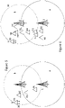
- Figures 5 and 6 illustrate how autonomous vehicles according to respective first and second embodiments of the invention may seek a suitable location for deployment.
- the difference between the embodiments is in the search strategy used to identify the direction of the serving base station's signal decay (step 103 in Figure 3 ).
- a directional antenna is used.
- an omnidirectional antenna is used, and the direction of decay determined by trial and error.
- the autonomous vehicle starts at a location 80. It determines that it is in range of a base station 1 and attaches to that base station (step 101). It then measures the signal strength and direction of the base station (step 103) and having determined that it is not close to the threshold signal quality it moves in the direction away from the base station to a second position 81, where the autonomous vehicle determines that the signal quality has now deteriorated to below a threshold (step 105), and that a handover is possible to another base station 2 (step 106). Being now within range of the second base station the autonomous vehicle then moves to a third position 82.
- the direction of the second base station 2 is determined (step 103) and the autonomous vehicle moves in the opposite direction until it reaches location 83 at which the signal quality again falls to the threshold value (step 105). As in this case no further handover is possible (step 107) the autonomous vehicle 10 stops (step 108) and activates its relay functionality 109.
- the autonomous vehicle starts at a location 90. It determines that it is in range of a base station 1 and attaches to that base station (step 101). It then measures the signal strength of the base station (step 103) and having determined that it is not close to the threshold signal quality it moves to a second position 91, where the process is repeated.
- the radio interface does not have a directional capability and so the initial move is made in a random direction, although making use of inputs from the proximity sensors 42, 43.
- the signal quality detected at the second location 91 is similar to that at the first location 90, indicating that the vehicle is "contouring" around the base station 1, so at one or more subsequent iterations (92, 93) different directions are attempted until a direction is discovered in which the signal quality deteriorates (step 94). Being still within range of the first base station the autonomous vehicle then continues to move in that direction until the autonomous vehicle reaches a position (95) where it determines that the signal quality has deteriorated to below a threshold (step 105), and that a handover is possible to another base station 2 (step 106).
- the autonomous vehicle searches again for a direction to move (96, 97, 98) until it reaches a location 99 at which the signal quality again falls to the threshold value (step 105). As in this case no further handover is possible (step 107) the autonomous vehicle 10 stops (step 108) and activates its relay functionality 109.
- the second search strategy is slower than the first, but does not require a directional antenna to identify the direction to travel.
- the search strategy will result in the mobile unit handing over between base stations according to which one is closest. It will eventually reach an equilibrium at a minimum point (such as "E" in Figure 1 ) at which the signal quality (from one or other of the base stations) improves in any direction the unit can travel. This therefore identifies an optimum point for the temporary base station to be located.
Landscapes
- Engineering & Computer Science (AREA)
- Computer Networks & Wireless Communication (AREA)
- Signal Processing (AREA)
- Physics & Mathematics (AREA)
- Aviation & Aerospace Engineering (AREA)
- General Physics & Mathematics (AREA)
- Radar, Positioning & Navigation (AREA)
- Remote Sensing (AREA)
- Automation & Control Theory (AREA)
- Astronomy & Astrophysics (AREA)
- Mobile Radio Communication Systems (AREA)
Claims (15)
- Equipement de point d'accès de communications à accès sans fil (10), agencé pour identifier un emplacement nécessitant une couverture sans fil améliorée et se déplacer jusqu'à cet endroit, disposant d'un système de balayage (50) pour détecter des transmissions provenant d'un ou plusieurs autres points d'accès de communications sans fil (1, 2, 3), d'un processeur (41) pour déterminer une direction dans laquelle la qualité de couverture des autres points d'accès de communications sans fil se détériore (103), d'un système de navigation pour commander un déplacement dans la direction d'une couverture décroissante, et d'un système de propulsion (31) et de direction pour déplacer l'équipement de point d'accès sous la commande du système de navigation, le processeur ayant la possibilité d'identifier un emplacement auquel il se trouve à une limite de couverture fournie par les autres points d'accès de communications sans fil, et de commencer à fonctionner en tant que point d'accès à l'emplacement ainsi identifié.
- Equipement de point d'accès de communications sans fil selon la revendication 1, agencé pour, lorsqu'il détecte qu'il se trouve à une limite de couverture d'un point d'accès de communications sans fil avec lequel il est en communication, rechercher un transfert sur un point d'accès de communications sans fil supplémentaire (106) et, si un transfert réussit, continuer de se déplacer dans une direction dans laquelle la qualité de couverture à partir du point d'accès supplémentaire se détériore, jusqu'à ce qu'un transfert supplémentaire soit lancé ou qu'il atteigne une limite de couverture fournie par l'autre point d'accès sans fil.
- Equipement de point d'accès de communications sans fil selon la revendication 1 ou la revendication 2, agencé pour établir une communication relais de liaison par le biais d'un point d'accès sans fil connecté à l'équipement de point d'accès de communications sans fil (10) .
- Equipement de point d'accès de communications sans fil selon la revendication 1, le processeur (41) ayant la possibilité d'identifier un emplacement auquel la qualité de couverture fournie par une pluralité d'autres points d'accès sans fil est à un minimum, et commencer à fonctionner en tant que point d'accès à l'emplacement ainsi identifié.
- Equipement de point d'accès de communications sans fil selon la revendication 1, la revendication 2, la revendication 3 ou la revendication 4, comportant une antenne directionnelle (51) pour détecter la direction dans laquelle la qualité de couverture de l'autre ou des autres points d'accès diminue.
- Equipement de point d'accès de communications sans fil selon la revendication 1, la revendication 2, la revendication 3 ou la revendication 4, dans lequel le processeur (41) est configuré pour commander le système de navigation dans un modèle de recherche afin d'identifier la direction dans laquelle la qualité de couverture du ou des points d'accès actuellement en service diminue.
- Equipement de point d'accès de communications sans fil selon la revendication 1, la revendication 2, la revendication 3, la revendication 4, la revendication 5 ou la revendication 6, configuré pour fonctionner en tant que relais entre un ou plusieurs points d'accès de communications sans fil supplémentaires et une connexion de liaison.
- Procédé de commande d'un équipement de point d'accès de communications à accès sans fil, comprenant les étapes de :- balayage pour détecter des transmissions à partir d'un ou plusieurs autres points d'accès de communications sans fil (101),- détermination d'une direction dans laquelle la qualité de couverture des autres points d'accès aux communications sans fil se détériore (103)- commande de l'équipement de point d'accès de communications sans fil pour qu'il se déplace dans la direction d'une couverture décroissante,- identification d'un emplacement à une limite de couverture fournie par les autres points d'accès sans fil (104), et- lancement d'un fonctionnement en tant que point d'accès à l'emplacement ainsi identifié (106).
- Procédé selon la revendication 8, dans lequel l'équipement de point d'accès de communications sans fil :- à l'emplacement ainsi identifié, tente un transfert (106) sur un deuxième point d'accès de communications sans fil- si un transfert est possible, répète les étapes précédentes avec le deuxième point d'accès sans fil et tout point d'accès sans fil suivant,- si un transfert n'est pas possible, se met à fonctionner en tant que point d'accès.
- Procédé selon la revendication 8 ou 9, dans lequel l'équipement de point d'accès de communications sans fil établit une communication relais de liaison (109) par le biais du point d'accès sans fil avec lequel il est actuellement en communication.
- Procédé selon la revendication 8, dans lequel l'équipement de point d'accès de communications sans fil identifie un emplacement auquel la qualité de couverture fournie par une pluralité d'autres points d'accès sans fil est à un minimum, et commence à fonctionner en tant que point d'accès à l'emplacement ainsi identifié.
- Procédé selon la revendication 8, la revendication 9, la revendication 10 ou la revendication 11, dans lequel la détermination d'une direction dans laquelle la qualité de couverture des autres points d'accès de communications sans fil diminue est réalisée par balayage avec une antenne directionnelle (51).
- Procédé selon la revendication 8, la revendication 9, la revendication 10, la revendication 11 ou la revendication 12, dans lequel la détermination d'une direction dans laquelle la qualité de couverture des autres points d'accès de communications sans fil diminue est réalisée en naviguant dans un modèle de recherche pour identifier la direction dans laquelle la qualité de couverture d'un point d'accès actuellement desservi diminue.
- Procédé dans lequel une pluralité de véhicules autonomes (10, 11, 12), comportant chacun un équipement de point d'accès de communications sans fil respectif et réalisant chacun le procédé selon la revendication 8, la revendication 9, la revendication 10, la revendication 11, la revendication 12 ou la revendication 13, est déployée de manière séquentielle, chacun de ces véhicules identifiant une limite de couverture sans fil fournie par des points d'accès de communications sans fil fixes et l'un quelconque des véhicules autonomes précédemment déployés, et se mettant à fonctionner en tant que point d'accès à la limite de la couverture sans fil ainsi identifiée.
- Procédé selon la revendication 14, dans lequel les équipements de communication d'accès sans fil associés à chaque véhicule autonome communiquent entre eux pour fournir un réseau relais connecté à un système de liaison par le biais d'au moins un point d'accès réseau fixe en communication avec un ou plusieurs des équipements de communications à accès sans fil.
Applications Claiming Priority (2)
| Application Number | Priority Date | Filing Date | Title |
|---|---|---|---|
| EP17186327 | 2017-08-15 | ||
| PCT/EP2018/070452 WO2019034391A1 (fr) | 2017-08-15 | 2018-07-27 | Coordination de raccordement de cellule mobile |
Publications (2)
| Publication Number | Publication Date |
|---|---|
| EP3669612A1 EP3669612A1 (fr) | 2020-06-24 |
| EP3669612B1 true EP3669612B1 (fr) | 2022-09-28 |
Family
ID=59631639
Family Applications (1)
| Application Number | Title | Priority Date | Filing Date |
|---|---|---|---|
| EP18743039.2A Active EP3669612B1 (fr) | 2017-08-15 | 2018-07-27 | Coordination de liaison raccordement des cellules mobiles |
Country Status (4)
| Country | Link |
|---|---|
| US (1) | US11071034B2 (fr) |
| EP (1) | EP3669612B1 (fr) |
| CN (1) | CN111034346B (fr) |
| WO (1) | WO2019034391A1 (fr) |
Families Citing this family (7)
| Publication number | Priority date | Publication date | Assignee | Title |
|---|---|---|---|---|
| KR102370493B1 (ko) * | 2017-10-30 | 2022-03-04 | 현대자동차주식회사 | 로봇을 이용한 공유 모빌리티 시스템 및 제어방법 |
| US11341787B2 (en) * | 2019-03-20 | 2022-05-24 | British Telecommunications Public Limited Company | Device management |
| US12142941B2 (en) | 2019-08-09 | 2024-11-12 | British Telecommunications Public Limited Company | Reverse powered wireless distribution point |
| WO2022069061A1 (fr) * | 2020-10-02 | 2022-04-07 | Telefonaktiebolaget Lm Ericsson (Publ) | Technique d'évaluation de qualité de connexion |
| US12200612B2 (en) * | 2022-01-18 | 2025-01-14 | GE Precision Healthcare LLC | Methods and systems for conditional scanning |
| JP2023118510A (ja) * | 2022-02-15 | 2023-08-25 | オムロン株式会社 | 走行装置 |
| WO2025171864A1 (fr) | 2024-02-13 | 2025-08-21 | Abb Schweiz Ag | Réseau de commande pour robots mobiles dans une installation |
Family Cites Families (43)
| Publication number | Priority date | Publication date | Assignee | Title |
|---|---|---|---|---|
| US2532966A (en) * | 1949-09-16 | 1950-12-05 | Thomas Tom | Wheelbarrow booster |
| US4842221A (en) | 1988-04-21 | 1989-06-27 | Westinghouse Electric Corp. | Lightning hardened tether cable and an aerostat tethered to a mooring system therewith |
| US6325330B1 (en) | 1998-08-18 | 2001-12-04 | Lockheed Martin Corporation | Power generation, transmission, and distribution system for an aerostat using a lightweight tether |
| US6804515B1 (en) | 2000-06-27 | 2004-10-12 | Motorola, Inc. | Transportable infrastructure for airborne cellular system |
| GB0102639D0 (en) | 2001-02-01 | 2001-03-21 | Daly Neil | Broadband communications system |
| IL150894A0 (en) | 2002-07-24 | 2003-04-10 | A method for measuring road traffic load based on analyzing cellular communications | |
| US7348930B2 (en) * | 2005-01-21 | 2008-03-25 | Rotani, Inc. | Method and apparatus for a radio transceiver |
| US7631834B1 (en) | 2006-02-24 | 2009-12-15 | Stealth Robotics, Llc | Aerial robot with dispensable conductive filament |
| US7510142B2 (en) | 2006-02-24 | 2009-03-31 | Stealth Robotics | Aerial robot |
| JP4822957B2 (ja) | 2006-06-30 | 2011-11-24 | 富士通株式会社 | 通信装置 |
| US8068937B2 (en) | 2008-02-09 | 2011-11-29 | Stephen Spencer Eaves | Power distribution system with fault protection using energy packet confirmation |
| JP5456695B2 (ja) | 2008-12-15 | 2014-04-02 | パナソニック株式会社 | 端末装置、基地局装置、通信システムおよびハンドオーバー制御方法 |
| CN102006639B (zh) | 2009-09-03 | 2014-01-01 | 华为技术有限公司 | 切换处理方法和系统、中继装置以及基站 |
| EP2296410B1 (fr) | 2009-09-10 | 2017-02-08 | Alcatel Lucent | Noeud de télécommunications et procédés |
| US20120075759A1 (en) | 2009-10-27 | 2012-03-29 | Stephen Spencer Eaves | Safe Exposed Conductor Power Distribution System |
| US8781637B2 (en) | 2009-10-27 | 2014-07-15 | Voltserver Inc. | Safe exposed conductor power distribution system |
| US9497714B2 (en) | 2010-09-24 | 2016-11-15 | Qualcomm Incorporated | Power control for a network of access points |
| EP2485516B1 (fr) | 2011-01-27 | 2018-05-02 | Alcatel Lucent | Couverture radio dans un système de télécommunication radio |
| AU2012294284A1 (en) | 2011-08-11 | 2014-02-27 | Interdigital Patent Holdings, Inc. | Mobile relay handover |
| EP2618601B1 (fr) | 2012-01-17 | 2014-09-24 | Alcatel Lucent | Identification de lacunes en matière de couverture |
| JP6337001B2 (ja) | 2012-12-07 | 2018-06-06 | ボルトサーバー インコーポレーティッドVoltserver,Inc. | 安全な露出導体電力分配システム |
| US8867418B2 (en) | 2013-02-17 | 2014-10-21 | Parallel Wireless, Inc. | Methods of incorporating an ad hoc cellular network into a fixed cellular network |
| US9585038B2 (en) | 2013-03-13 | 2017-02-28 | Futurewei Technologies, Inc. | Forward traffic announcements for enhanced resource reservation in high speed mobile relays |
| US9661515B2 (en) | 2013-04-25 | 2017-05-23 | Plume Design, Inc. | Cloud-based management platform for heterogeneous wireless devices |
| US9474000B2 (en) | 2013-07-31 | 2016-10-18 | Qualcomm Incorporated | Handover and reselection searching using predictive mobility |
| US9184795B2 (en) | 2014-01-26 | 2015-11-10 | VoltServer, Inc. | Packet energy transfer in-line communications |
| US9859972B2 (en) * | 2014-02-17 | 2018-01-02 | Ubiqomm Llc | Broadband access to mobile platforms using drone/UAV background |
| EP3737141B1 (fr) | 2014-03-18 | 2022-06-01 | Telefonaktiebolaget LM Ericsson (publ) | Fourniture d'une couverture d'un réseau de communication sans fil avec des stations mobiles sur des robots ou des drones |
| EP2938117B1 (fr) * | 2014-04-24 | 2017-12-27 | Alcatel Lucent | Ajustement de la position gépgraphique d'une station de base drone |
| CN105083520A (zh) | 2014-05-22 | 2015-11-25 | 南京大五教育科技有限公司 | 利用热气球将移动基站带入平流层恢复通讯 |
| US9363008B2 (en) * | 2014-07-22 | 2016-06-07 | International Business Machines Corporation | Deployment criteria for unmanned aerial vehicles to improve cellular phone communications |
| EP3172936B1 (fr) | 2014-07-25 | 2020-09-16 | Telefonaktiebolaget LM Ericsson (publ) | Technique d'exploitation de station de base radio mobile |
| US9302782B2 (en) | 2014-08-18 | 2016-04-05 | Sunlight Photonics Inc. | Methods and apparatus for a distributed airborne wireless communications fleet |
| JP6266174B2 (ja) | 2014-10-21 | 2018-01-24 | ボルトサーバー インコーポレーティッドVoltserver,Inc. | デジタル電力レシーバシステム |
| US9853689B2 (en) | 2014-11-07 | 2017-12-26 | VoltServer, Inc. | Packet energy transfer power control elements |
| US9913095B2 (en) * | 2014-11-19 | 2018-03-06 | Parallel Wireless, Inc. | Enhanced mobile base station |
| GB2532966A (en) | 2014-12-03 | 2016-06-08 | Nokia Technologies Oy | Control of a drone |
| CN104703120B (zh) * | 2015-04-01 | 2018-12-25 | 南京佰联信息技术有限公司 | 移动通信方法和装置 |
| US20160363457A1 (en) | 2015-06-10 | 2016-12-15 | Motorola Solutions, Inc | Method and apparatus for dispatching network equipment within a communication system |
| CN205971849U (zh) * | 2016-07-13 | 2017-02-22 | 京信通信系统(中国)有限公司 | 一种无人机 |
| EP3288140A1 (fr) | 2016-08-22 | 2018-02-28 | EE Limited | Fourniture de puissance électrique |
| US10178531B2 (en) | 2016-09-15 | 2019-01-08 | Qualcomm Incorporated | Methods and apparatus for efficient sensor data sharing in a vehicle-to-vehicle (V2V) network |
| GB2563226A (en) * | 2017-06-06 | 2018-12-12 | Bae Systems Plc | Mobile communications network |
-
2018
- 2018-07-27 EP EP18743039.2A patent/EP3669612B1/fr active Active
- 2018-07-27 US US16/637,080 patent/US11071034B2/en active Active
- 2018-07-27 CN CN201880052614.0A patent/CN111034346B/zh active Active
- 2018-07-27 WO PCT/EP2018/070452 patent/WO2019034391A1/fr not_active Ceased
Also Published As
| Publication number | Publication date |
|---|---|
| WO2019034391A1 (fr) | 2019-02-21 |
| CN111034346B (zh) | 2022-08-09 |
| EP3669612A1 (fr) | 2020-06-24 |
| US20200252851A1 (en) | 2020-08-06 |
| CN111034346A (zh) | 2020-04-17 |
| US11071034B2 (en) | 2021-07-20 |
Similar Documents
| Publication | Publication Date | Title |
|---|---|---|
| EP3669612B1 (fr) | Coordination de liaison raccordement des cellules mobiles | |
| Mozaffari et al. | Toward 6G with connected sky: UAVs and beyond | |
| US12172535B2 (en) | Unmanned aerial vehicle drive testing and mapping of carrier signals | |
| US11943041B2 (en) | Dynamic shielding system of cellular signals for an antenna of an unmanned aerial vehicle | |
| US10971022B2 (en) | Drone user equipment indication | |
| Chen et al. | Optimal positioning of flying relays for wireless networks: A LOS map approach | |
| EP2938117B1 (fr) | Ajustement de la position gépgraphique d'une station de base drone | |
| US12574101B2 (en) | Location dependent relay node configuration | |
| KR101709685B1 (ko) | 선박을 위한 이동통신 중계 서비스 시스템 및 방법 | |
| TWI729531B (zh) | 無人載具無線通訊中繼系統 | |
| WO2015114572A1 (fr) | Système mis en œuvre par ordinateur et procédé servant à fournir des liaisons de communication robustes à des véhicules aériens sans pilote | |
| CN107534224A (zh) | 指向无人航空载具(uav)以进行网络接入的地面终端和网关波束 | |
| JP6928075B2 (ja) | 無線中継システム | |
| US11452034B2 (en) | Distance-based serving cell selection for communications between an aerial vehicle and a cellular radio access network | |
| EP3520245B1 (fr) | Téléphonie cellulaire | |
| GB2565559A (en) | Moving cell backhaul coordination | |
| EP4561203A1 (fr) | Positionnement d'ue | |
| WO2017142520A1 (fr) | Identification et communication d'accident dans des véhicules | |
| KR20250089771A (ko) | 드론을 활용한 신규 기지국의 핸드오버 테스트 시스템 및 방법 | |
| KR20240033587A (ko) | 핸드오버 지원 장치 및 방법 | |
| Huang et al. | Reactive deployment of flying robot base station over disaster areas | |
| CN119997077B (zh) | 一种基于无人机的蜂窝网络覆盖空洞检测修复方法 | |
| Shang et al. | Anchor-and-Connect: Robotic Aerial Base Stations Transforming 6G Infrastructure | |
| Cao et al. | Joint Trajectory Optimization and Resource Allocation of UAV in Urban ISAC Network | |
| Vinayagam et al. | High-Gain Antenna Arrays for Drone-based Disaster Relief Communication Networks |
Legal Events
| Date | Code | Title | Description |
|---|---|---|---|
| STAA | Information on the status of an ep patent application or granted ep patent |
Free format text: STATUS: UNKNOWN |
|
| STAA | Information on the status of an ep patent application or granted ep patent |
Free format text: STATUS: THE INTERNATIONAL PUBLICATION HAS BEEN MADE |
|
| PUAI | Public reference made under article 153(3) epc to a published international application that has entered the european phase |
Free format text: ORIGINAL CODE: 0009012 |
|
| STAA | Information on the status of an ep patent application or granted ep patent |
Free format text: STATUS: REQUEST FOR EXAMINATION WAS MADE |
|
| 17P | Request for examination filed |
Effective date: 20200128 |
|
| AK | Designated contracting states |
Kind code of ref document: A1 Designated state(s): AL AT BE BG CH CY CZ DE DK EE ES FI FR GB GR HR HU IE IS IT LI LT LU LV MC MK MT NL NO PL PT RO RS SE SI SK SM TR |
|
| AX | Request for extension of the european patent |
Extension state: BA ME |
|
| DAV | Request for validation of the european patent (deleted) | ||
| DAX | Request for extension of the european patent (deleted) | ||
| RIC1 | Information provided on ipc code assigned before grant |
Ipc: H04W 84/04 20090101ALN20211221BHEP Ipc: H04W 48/16 20090101ALN20211221BHEP Ipc: H04W 36/00 20090101ALN20211221BHEP Ipc: H04W 84/06 20090101ALN20211221BHEP Ipc: H04W 24/02 20090101ALN20211221BHEP Ipc: H04B 7/185 20060101ALI20211221BHEP Ipc: H04W 84/00 20090101ALI20211221BHEP Ipc: H04B 7/26 20060101AFI20211221BHEP |
|
| RAP3 | Party data changed (applicant data changed or rights of an application transferred) |
Owner name: BRITISH TELECOMMUNICATIONS PUBLIC LIMITED COMPANY |
|
| REG | Reference to a national code |
Ref country code: DE Ref legal event code: R079 Ref document number: 602018041130 Country of ref document: DE Free format text: PREVIOUS MAIN CLASS: H04W0084000000 Ipc: H04B0007260000 |
|
| RIC1 | Information provided on ipc code assigned before grant |
Ipc: H04W 84/04 20090101ALN20220203BHEP Ipc: H04W 48/16 20090101ALN20220203BHEP Ipc: H04W 36/00 20090101ALN20220203BHEP Ipc: H04W 84/06 20090101ALN20220203BHEP Ipc: H04W 24/02 20090101ALN20220203BHEP Ipc: H04B 7/185 20060101ALI20220203BHEP Ipc: H04W 84/00 20090101ALI20220203BHEP Ipc: H04B 7/26 20060101AFI20220203BHEP |
|
| GRAP | Despatch of communication of intention to grant a patent |
Free format text: ORIGINAL CODE: EPIDOSNIGR1 |
|
| STAA | Information on the status of an ep patent application or granted ep patent |
Free format text: STATUS: GRANT OF PATENT IS INTENDED |
|
| RIC1 | Information provided on ipc code assigned before grant |
Ipc: H04W 84/04 20090101ALN20220225BHEP Ipc: H04W 48/16 20090101ALN20220225BHEP Ipc: H04W 36/00 20090101ALN20220225BHEP Ipc: H04W 84/06 20090101ALN20220225BHEP Ipc: H04W 24/02 20090101ALN20220225BHEP Ipc: H04B 7/185 20060101ALI20220225BHEP Ipc: H04W 84/00 20090101ALI20220225BHEP Ipc: H04B 7/26 20060101AFI20220225BHEP |
|
| INTG | Intention to grant announced |
Effective date: 20220317 |
|
| GRAS | Grant fee paid |
Free format text: ORIGINAL CODE: EPIDOSNIGR3 |
|
| GRAA | (expected) grant |
Free format text: ORIGINAL CODE: 0009210 |
|
| STAA | Information on the status of an ep patent application or granted ep patent |
Free format text: STATUS: THE PATENT HAS BEEN GRANTED |
|
| AK | Designated contracting states |
Kind code of ref document: B1 Designated state(s): AL AT BE BG CH CY CZ DE DK EE ES FI FR GB GR HR HU IE IS IT LI LT LU LV MC MK MT NL NO PL PT RO RS SE SI SK SM TR |
|
| REG | Reference to a national code |
Ref country code: GB Ref legal event code: FG4D |
|
| REG | Reference to a national code |
Ref country code: CH Ref legal event code: EP |
|
| REG | Reference to a national code |
Ref country code: DE Ref legal event code: R096 Ref document number: 602018041130 Country of ref document: DE |
|
| REG | Reference to a national code |
Ref country code: AT Ref legal event code: REF Ref document number: 1521943 Country of ref document: AT Kind code of ref document: T Effective date: 20221015 |
|
| REG | Reference to a national code |
Ref country code: IE Ref legal event code: FG4D |
|
| REG | Reference to a national code |
Ref country code: LT Ref legal event code: MG9D |
|
| PG25 | Lapsed in a contracting state [announced via postgrant information from national office to epo] |
Ref country code: SE Free format text: LAPSE BECAUSE OF FAILURE TO SUBMIT A TRANSLATION OF THE DESCRIPTION OR TO PAY THE FEE WITHIN THE PRESCRIBED TIME-LIMIT Effective date: 20220928 Ref country code: RS Free format text: LAPSE BECAUSE OF FAILURE TO SUBMIT A TRANSLATION OF THE DESCRIPTION OR TO PAY THE FEE WITHIN THE PRESCRIBED TIME-LIMIT Effective date: 20220928 Ref country code: NO Free format text: LAPSE BECAUSE OF FAILURE TO SUBMIT A TRANSLATION OF THE DESCRIPTION OR TO PAY THE FEE WITHIN THE PRESCRIBED TIME-LIMIT Effective date: 20221228 Ref country code: LV Free format text: LAPSE BECAUSE OF FAILURE TO SUBMIT A TRANSLATION OF THE DESCRIPTION OR TO PAY THE FEE WITHIN THE PRESCRIBED TIME-LIMIT Effective date: 20220928 Ref country code: LT Free format text: LAPSE BECAUSE OF FAILURE TO SUBMIT A TRANSLATION OF THE DESCRIPTION OR TO PAY THE FEE WITHIN THE PRESCRIBED TIME-LIMIT Effective date: 20220928 Ref country code: FI Free format text: LAPSE BECAUSE OF FAILURE TO SUBMIT A TRANSLATION OF THE DESCRIPTION OR TO PAY THE FEE WITHIN THE PRESCRIBED TIME-LIMIT Effective date: 20220928 |
|
| REG | Reference to a national code |
Ref country code: NL Ref legal event code: MP Effective date: 20220928 |
|
| REG | Reference to a national code |
Ref country code: AT Ref legal event code: MK05 Ref document number: 1521943 Country of ref document: AT Kind code of ref document: T Effective date: 20220928 |
|
| PG25 | Lapsed in a contracting state [announced via postgrant information from national office to epo] |
Ref country code: HR Free format text: LAPSE BECAUSE OF FAILURE TO SUBMIT A TRANSLATION OF THE DESCRIPTION OR TO PAY THE FEE WITHIN THE PRESCRIBED TIME-LIMIT Effective date: 20220928 Ref country code: GR Free format text: LAPSE BECAUSE OF FAILURE TO SUBMIT A TRANSLATION OF THE DESCRIPTION OR TO PAY THE FEE WITHIN THE PRESCRIBED TIME-LIMIT Effective date: 20221229 |
|
| PG25 | Lapsed in a contracting state [announced via postgrant information from national office to epo] |
Ref country code: SM Free format text: LAPSE BECAUSE OF FAILURE TO SUBMIT A TRANSLATION OF THE DESCRIPTION OR TO PAY THE FEE WITHIN THE PRESCRIBED TIME-LIMIT Effective date: 20220928 Ref country code: RO Free format text: LAPSE BECAUSE OF FAILURE TO SUBMIT A TRANSLATION OF THE DESCRIPTION OR TO PAY THE FEE WITHIN THE PRESCRIBED TIME-LIMIT Effective date: 20220928 Ref country code: PT Free format text: LAPSE BECAUSE OF FAILURE TO SUBMIT A TRANSLATION OF THE DESCRIPTION OR TO PAY THE FEE WITHIN THE PRESCRIBED TIME-LIMIT Effective date: 20230130 Ref country code: ES Free format text: LAPSE BECAUSE OF FAILURE TO SUBMIT A TRANSLATION OF THE DESCRIPTION OR TO PAY THE FEE WITHIN THE PRESCRIBED TIME-LIMIT Effective date: 20220928 Ref country code: CZ Free format text: LAPSE BECAUSE OF FAILURE TO SUBMIT A TRANSLATION OF THE DESCRIPTION OR TO PAY THE FEE WITHIN THE PRESCRIBED TIME-LIMIT Effective date: 20220928 Ref country code: AT Free format text: LAPSE BECAUSE OF FAILURE TO SUBMIT A TRANSLATION OF THE DESCRIPTION OR TO PAY THE FEE WITHIN THE PRESCRIBED TIME-LIMIT Effective date: 20220928 |
|
| PG25 | Lapsed in a contracting state [announced via postgrant information from national office to epo] |
Ref country code: SK Free format text: LAPSE BECAUSE OF FAILURE TO SUBMIT A TRANSLATION OF THE DESCRIPTION OR TO PAY THE FEE WITHIN THE PRESCRIBED TIME-LIMIT Effective date: 20220928 Ref country code: PL Free format text: LAPSE BECAUSE OF FAILURE TO SUBMIT A TRANSLATION OF THE DESCRIPTION OR TO PAY THE FEE WITHIN THE PRESCRIBED TIME-LIMIT Effective date: 20220928 Ref country code: IS Free format text: LAPSE BECAUSE OF FAILURE TO SUBMIT A TRANSLATION OF THE DESCRIPTION OR TO PAY THE FEE WITHIN THE PRESCRIBED TIME-LIMIT Effective date: 20230128 Ref country code: EE Free format text: LAPSE BECAUSE OF FAILURE TO SUBMIT A TRANSLATION OF THE DESCRIPTION OR TO PAY THE FEE WITHIN THE PRESCRIBED TIME-LIMIT Effective date: 20220928 |
|
| REG | Reference to a national code |
Ref country code: DE Ref legal event code: R097 Ref document number: 602018041130 Country of ref document: DE |
|
| PG25 | Lapsed in a contracting state [announced via postgrant information from national office to epo] |
Ref country code: NL Free format text: LAPSE BECAUSE OF FAILURE TO SUBMIT A TRANSLATION OF THE DESCRIPTION OR TO PAY THE FEE WITHIN THE PRESCRIBED TIME-LIMIT Effective date: 20220928 Ref country code: AL Free format text: LAPSE BECAUSE OF FAILURE TO SUBMIT A TRANSLATION OF THE DESCRIPTION OR TO PAY THE FEE WITHIN THE PRESCRIBED TIME-LIMIT Effective date: 20220928 |
|
| PG25 | Lapsed in a contracting state [announced via postgrant information from national office to epo] |
Ref country code: DK Free format text: LAPSE BECAUSE OF FAILURE TO SUBMIT A TRANSLATION OF THE DESCRIPTION OR TO PAY THE FEE WITHIN THE PRESCRIBED TIME-LIMIT Effective date: 20220928 |
|
| P01 | Opt-out of the competence of the unified patent court (upc) registered |
Effective date: 20230623 |
|
| PLBE | No opposition filed within time limit |
Free format text: ORIGINAL CODE: 0009261 |
|
| STAA | Information on the status of an ep patent application or granted ep patent |
Free format text: STATUS: NO OPPOSITION FILED WITHIN TIME LIMIT |
|
| 26N | No opposition filed |
Effective date: 20230629 |
|
| PG25 | Lapsed in a contracting state [announced via postgrant information from national office to epo] |
Ref country code: SI Free format text: LAPSE BECAUSE OF FAILURE TO SUBMIT A TRANSLATION OF THE DESCRIPTION OR TO PAY THE FEE WITHIN THE PRESCRIBED TIME-LIMIT Effective date: 20220928 |
|
| PG25 | Lapsed in a contracting state [announced via postgrant information from national office to epo] |
Ref country code: MC Free format text: LAPSE BECAUSE OF FAILURE TO SUBMIT A TRANSLATION OF THE DESCRIPTION OR TO PAY THE FEE WITHIN THE PRESCRIBED TIME-LIMIT Effective date: 20220928 |
|
| PG25 | Lapsed in a contracting state [announced via postgrant information from national office to epo] |
Ref country code: MC Free format text: LAPSE BECAUSE OF FAILURE TO SUBMIT A TRANSLATION OF THE DESCRIPTION OR TO PAY THE FEE WITHIN THE PRESCRIBED TIME-LIMIT Effective date: 20220928 |
|
| REG | Reference to a national code |
Ref country code: CH Ref legal event code: PL |
|
| REG | Reference to a national code |
Ref country code: BE Ref legal event code: MM Effective date: 20230731 |
|
| PG25 | Lapsed in a contracting state [announced via postgrant information from national office to epo] |
Ref country code: LU Free format text: LAPSE BECAUSE OF NON-PAYMENT OF DUE FEES Effective date: 20230727 |
|
| PG25 | Lapsed in a contracting state [announced via postgrant information from national office to epo] |
Ref country code: LU Free format text: LAPSE BECAUSE OF NON-PAYMENT OF DUE FEES Effective date: 20230727 |
|
| REG | Reference to a national code |
Ref country code: IE Ref legal event code: MM4A |
|
| PG25 | Lapsed in a contracting state [announced via postgrant information from national office to epo] |
Ref country code: CH Free format text: LAPSE BECAUSE OF NON-PAYMENT OF DUE FEES Effective date: 20230731 |
|
| PG25 | Lapsed in a contracting state [announced via postgrant information from national office to epo] |
Ref country code: IT Free format text: LAPSE BECAUSE OF FAILURE TO SUBMIT A TRANSLATION OF THE DESCRIPTION OR TO PAY THE FEE WITHIN THE PRESCRIBED TIME-LIMIT Effective date: 20220928 Ref country code: BE Free format text: LAPSE BECAUSE OF NON-PAYMENT OF DUE FEES Effective date: 20230731 |
|
| PG25 | Lapsed in a contracting state [announced via postgrant information from national office to epo] |
Ref country code: IE Free format text: LAPSE BECAUSE OF NON-PAYMENT OF DUE FEES Effective date: 20230727 |
|
| PG25 | Lapsed in a contracting state [announced via postgrant information from national office to epo] |
Ref country code: IE Free format text: LAPSE BECAUSE OF NON-PAYMENT OF DUE FEES Effective date: 20230727 |
|
| PG25 | Lapsed in a contracting state [announced via postgrant information from national office to epo] |
Ref country code: BG Free format text: LAPSE BECAUSE OF FAILURE TO SUBMIT A TRANSLATION OF THE DESCRIPTION OR TO PAY THE FEE WITHIN THE PRESCRIBED TIME-LIMIT Effective date: 20220928 |
|
| PG25 | Lapsed in a contracting state [announced via postgrant information from national office to epo] |
Ref country code: BG Free format text: LAPSE BECAUSE OF FAILURE TO SUBMIT A TRANSLATION OF THE DESCRIPTION OR TO PAY THE FEE WITHIN THE PRESCRIBED TIME-LIMIT Effective date: 20220928 |
|
| PGFP | Annual fee paid to national office [announced via postgrant information from national office to epo] |
Ref country code: GB Payment date: 20250619 Year of fee payment: 8 |
|
| PGFP | Annual fee paid to national office [announced via postgrant information from national office to epo] |
Ref country code: FR Payment date: 20250620 Year of fee payment: 8 |
|
| PG25 | Lapsed in a contracting state [announced via postgrant information from national office to epo] |
Ref country code: CY Free format text: LAPSE BECAUSE OF FAILURE TO SUBMIT A TRANSLATION OF THE DESCRIPTION OR TO PAY THE FEE WITHIN THE PRESCRIBED TIME-LIMIT; INVALID AB INITIO Effective date: 20180727 |
|
| PG25 | Lapsed in a contracting state [announced via postgrant information from national office to epo] |
Ref country code: HU Free format text: LAPSE BECAUSE OF FAILURE TO SUBMIT A TRANSLATION OF THE DESCRIPTION OR TO PAY THE FEE WITHIN THE PRESCRIBED TIME-LIMIT; INVALID AB INITIO Effective date: 20180727 |
|
| PGFP | Annual fee paid to national office [announced via postgrant information from national office to epo] |
Ref country code: DE Payment date: 20250620 Year of fee payment: 8 |
|
| PG25 | Lapsed in a contracting state [announced via postgrant information from national office to epo] |
Ref country code: TR Free format text: LAPSE BECAUSE OF FAILURE TO SUBMIT A TRANSLATION OF THE DESCRIPTION OR TO PAY THE FEE WITHIN THE PRESCRIBED TIME-LIMIT Effective date: 20220928 |