EP3669614B1 - Mesures de puissance à six ports - Google Patents
Mesures de puissance à six ports Download PDFInfo
- Publication number
- EP3669614B1 EP3669614B1 EP18765200.3A EP18765200A EP3669614B1 EP 3669614 B1 EP3669614 B1 EP 3669614B1 EP 18765200 A EP18765200 A EP 18765200A EP 3669614 B1 EP3669614 B1 EP 3669614B1
- Authority
- EP
- European Patent Office
- Prior art keywords
- port
- power
- signal
- ports
- solid state
- Prior art date
- Legal status (The legal status is an assumption and is not a legal conclusion. Google has not performed a legal analysis and makes no representation as to the accuracy of the status listed.)
- Not-in-force
Links
Images

Classifications
-
- H—ELECTRICITY
- H05—ELECTRIC TECHNIQUES NOT OTHERWISE PROVIDED FOR
- H05B—ELECTRIC HEATING; ELECTRIC LIGHT SOURCES NOT OTHERWISE PROVIDED FOR; CIRCUIT ARRANGEMENTS FOR ELECTRIC LIGHT SOURCES, IN GENERAL
- H05B6/00—Heating by electric, magnetic or electromagnetic fields
- H05B6/64—Heating using microwaves
- H05B6/70—Feed lines
-
- H—ELECTRICITY
- H01—ELECTRIC ELEMENTS
- H01Q—ANTENNAS, i.e. RADIO AERIALS
- H01Q1/00—Details of, or arrangements associated with, antennas
- H01Q1/52—Means for reducing coupling between antennas; Means for reducing coupling between an antenna and another structure
- H01Q1/521—Means for reducing coupling between antennas; Means for reducing coupling between an antenna and another structure reducing the coupling between adjacent antennas
-
- H—ELECTRICITY
- H01—ELECTRIC ELEMENTS
- H01Q—ANTENNAS, i.e. RADIO AERIALS
- H01Q21/00—Antenna arrays or systems
- H01Q21/06—Arrays of individually energised antenna units similarly polarised and spaced apart
- H01Q21/061—Two dimensional planar arrays
-
- H—ELECTRICITY
- H01—ELECTRIC ELEMENTS
- H01Q—ANTENNAS, i.e. RADIO AERIALS
- H01Q5/00—Arrangements for simultaneous operation of antennas on two or more different wavebands, e.g. dual-band or multi-band arrangements
- H01Q5/30—Arrangements for providing operation on different wavebands
- H01Q5/307—Individual or coupled radiating elements, each element being fed in an unspecified way
-
- H—ELECTRICITY
- H05—ELECTRIC TECHNIQUES NOT OTHERWISE PROVIDED FOR
- H05B—ELECTRIC HEATING; ELECTRIC LIGHT SOURCES NOT OTHERWISE PROVIDED FOR; CIRCUIT ARRANGEMENTS FOR ELECTRIC LIGHT SOURCES, IN GENERAL
- H05B6/00—Heating by electric, magnetic or electromagnetic fields
- H05B6/64—Heating using microwaves
- H05B6/66—Circuits
- H05B6/68—Circuits for monitoring or control
-
- H—ELECTRICITY
- H05—ELECTRIC TECHNIQUES NOT OTHERWISE PROVIDED FOR
- H05B—ELECTRIC HEATING; ELECTRIC LIGHT SOURCES NOT OTHERWISE PROVIDED FOR; CIRCUIT ARRANGEMENTS FOR ELECTRIC LIGHT SOURCES, IN GENERAL
- H05B6/00—Heating by electric, magnetic or electromagnetic fields
- H05B6/64—Heating using microwaves
- H05B6/70—Feed lines
- H05B6/702—Feed lines using coaxial cables
-
- H—ELECTRICITY
- H05—ELECTRIC TECHNIQUES NOT OTHERWISE PROVIDED FOR
- H05B—ELECTRIC HEATING; ELECTRIC LIGHT SOURCES NOT OTHERWISE PROVIDED FOR; CIRCUIT ARRANGEMENTS FOR ELECTRIC LIGHT SOURCES, IN GENERAL
- H05B6/00—Heating by electric, magnetic or electromagnetic fields
- H05B6/64—Heating using microwaves
- H05B6/70—Feed lines
- H05B6/705—Feed lines using microwave tuning
-
- H—ELECTRICITY
- H05—ELECTRIC TECHNIQUES NOT OTHERWISE PROVIDED FOR
- H05B—ELECTRIC HEATING; ELECTRIC LIGHT SOURCES NOT OTHERWISE PROVIDED FOR; CIRCUIT ARRANGEMENTS FOR ELECTRIC LIGHT SOURCES, IN GENERAL
- H05B6/00—Heating by electric, magnetic or electromagnetic fields
- H05B6/64—Heating using microwaves
- H05B6/72—Radiators or antennas
-
- Y—GENERAL TAGGING OF NEW TECHNOLOGICAL DEVELOPMENTS; GENERAL TAGGING OF CROSS-SECTIONAL TECHNOLOGIES SPANNING OVER SEVERAL SECTIONS OF THE IPC; TECHNICAL SUBJECTS COVERED BY FORMER USPC CROSS-REFERENCE ART COLLECTIONS [XRACs] AND DIGESTS
- Y02—TECHNOLOGIES OR APPLICATIONS FOR MITIGATION OR ADAPTATION AGAINST CLIMATE CHANGE
- Y02B—CLIMATE CHANGE MITIGATION TECHNOLOGIES RELATED TO BUILDINGS, e.g. HOUSING, HOUSE APPLIANCES OR RELATED END-USER APPLICATIONS
- Y02B40/00—Technologies aiming at improving the efficiency of home appliances, e.g. induction cooking or efficient technologies for refrigerators, freezers or dish washers
Definitions
- the present invention in some embodiments thereof, relates to the field of controlling heating using sensors, and more particularly, but not exclusively, for using RF for the sensing and/or for the heating.
- European patent application No. 2199753 is titled "Fluid cylinder with a microwave measuring assembly and method for recording at least one parameter".
- Fig. 2 in this patent application describes an evaluation device arranged on a printed circuit board.
- the evaluation device includes a six-port circuit comprising four power measurement ports.
- WO 03/090313 describes a transceiver for a millimeter wave signal, consisting of a PCB having PCB microstrip lines and PCB waveguide apertures, and one or more transmitter modules and one or more receiver modules mounted on the PCB.
- Each module has a single microstrip-waveguide transition and a microstrip-microstrip transition.
- the microstrip-waveguide transition of each module couples to one of the PCB waveguide apertures via a PCB-module waveguide-waveguide transition.
- the microstrip-microstrip transition of each module couples to one of the PCB microstrip lines via a PCB-module microstrip-microstrip transition.
- the PCB-module transitions are low tolerance, facilitating implementation of the transceiver.
- EP 1471773 describes distributed high power solid state microwave sources provided to improve the efficiency of microwave heating applications.
- a plurality of solid state microwave sources are be distributed throughout and/or adjacent to a microwave environment with the microwave power output of the solid state microwave sources being directed toward the chamber.
- the distribution of the plurality of solid state microwave devices can be customized to the specific size and shape of the microwave chamber and/or specific regions/ compartments of the microwave chambers.
- EP 1676463 describes a surface-heating system which heats a surface with a high-power wavefront at a millimeter-wave frequency.
- the high-power wavefront may be a collimated wavefront or a converging or diverging wavefront.
- the system includes a frequency generator to generate a lower-power millimeter-wave frequency signal, and an active-array antenna system to amplify the millimeter-wave frequency and generate the high-power wavefront in a direction of a surface for heating the surface.
- a frequency generator and power amplifier may generate a high-power power millimeter-wave frequency signal, and a passive-array antenna system may provide the high-power wavefront in a direction of the surface.
- a thermal-sensing subsystem may measure the surface temperature and generate a control signal to maintain the surface temperature within a predetermined temperature range.
- aspects of the present disclosure may be embodied as a system, method or computer program product. Accordingly, aspects of the present disclosure may take the form of an entirely hardware embodiment, an entirely software embodiment (including firmware, resident software, microcode, etc.) or an embodiment combining software and hardware aspects that may all generally be referred to herein as a "circuit,” “module” or “system” (e.g., a method may be implemented using "computer circuitry”). Furthermore, some embodiments of the present disclosure may take the form of a computer program product embodied in one or more computer readable medium(s) having computer readable program code embodied thereon.
- Implementation of the method and/or system of some embodiments of the present disclosure can involve performing and/or completing selected tasks manually, automatically, or a combination thereof. Moreover, according to actual instrumentation and equipment of some embodiments of the method and/or system of the present disclosure, several selected tasks could be implemented by hardware, by software or by firmware and/or by a combination thereof, e.g., using an operating system.
- hardware for performing selected tasks according to some embodiments of the present disclosure could be implemented as a chip or a circuit.
- selected tasks according to some embodiments of the present disclosure could be implemented as a plurality of software instructions being executed by a computer using any suitable operating system.
- one or more tasks performed in method and/or by system are performed by a data processor (also referred to herein as a "digital processor", in reference to data processors which operate using groups of digital bits), such as a computing platform for executing a plurality of instructions.
- the data processor includes a volatile memory for storing instructions and/or data and/or a non-volatile storage, for example, a magnetic hard-disk and/or removable media, for storing instructions and/or data.
- a network connection is provided as well.
- a display and/or a user input device such as a keyboard or mouse are optionally provided as well. Any of these implementations are referred to herein more generally as instances of computer circuitry.
- the computer readable medium may be a computer readable signal medium or a computer readable storage medium.
- a computer readable storage medium may be, for example, but not limited to, an electronic, magnetic, optical, electromagnetic, infrared, or semiconductor system, apparatus, or device, or any suitable combination of the foregoing.
- a computer readable storage medium may be any tangible medium that can contain, or store a program for use by or in connection with an instruction execution system, apparatus, or device .
- a computer readable storage medium may also contain or store information for use by such a program, for example, data structured in the way it is recorded by the computer readable storage medium so that a computer program can access it as, for example, one or more tables, lists, arrays, data trees, and/or another data structure.
- a computer readable storage medium which records data in a form retrievable as groups of digital bits is also referred to as a digital memory.
- a computer readable storage medium in some embodiments, is optionally also used as a computer writable storage medium, in the case of a computer readable storage medium which is not read-only in nature, and/or in a read-only state.
- a data processor is said to be “configured” to perform data processing actions insofar as it is coupled to a computer readable memory to receive instructions and/or data therefrom, process them, and/or store processing results in the same or another computer readable storage memory.
- the processing performed (optionally on the data) is specified by the instructions.
- the act of processing may be referred to additionally or alternatively by one or more other terms; for example: comparing, estimating, determining, calculating, identifying, associating, storing, analyzing, selecting, and/or transforming.
- a digital processor receives instructions and data from a digital memory, processes the data according to the instructions, and/or stores processing results in the digital memory.
- "providing" processing results comprises one or more of transmitting, storing and/or presenting processing results. Presenting optionally comprises showing on a display, indicating by sound, printing on a printout, or otherwise giving results in a form accessible to human sensory capabilities.
- a computer readable signal medium may include a propagated data signal with computer readable program code embodied therein, for example, in baseband or as part of a carrier wave. Such a propagated signal may take any of a variety of forms, including, but not limited to, electro-magnetic, optical, or any suitable combination thereof.
- a computer readable signal medium may be any computer readable medium that is not a computer readable storage medium and that can communicate, propagate, or transport a program for use by or in connection with an instruction execution system, apparatus, or device.
- Program code embodied on a computer readable medium and/or data used thereby may be transmitted using any appropriate medium, including but not limited to wireless, wireline, optical fiber cable, RF, etc., or any suitable combination of the foregoing.
- Computer program code for carrying out operations for some embodiments of the present disclosure may be written in any combination of one or more programming languages, including an object oriented programming language such as Java, Smalltalk, C++ or the like and conventional procedural programming languages, such as the "C" programming language or similar programming languages.
- the program code may execute entirely on the user's computer, partly on the user's computer, as a stand-alone software package, partly on the user's computer and partly on a remote computer or entirely on the remote computer or server.
- the remote computer may be connected to the user's computer through any type of network, including a local area network (LAN) or a wide area network (WAN), or the connection may be made to an external computer (for example, through the Internet using an Internet Service Provider(LAN) or a wide area network (WAN), or the connection may be made to an external computer (for example, through the Internet using an Internet Service Provider(LAN) or a wide area network (WAN), or the connection may be made to an external computer (for example, through the Internet using an Internet Service Provider
- These computer program instructions may also be stored in a computer readable medium that can direct a computer, other programmable data processing apparatus, or other devices to function in a particular manner, such that the instructions stored in the computer readable medium produce an article of manufacture including instructions which implement the function/act specified in the flowchart and/or block diagram block or blocks.
- the computer program instructions may also be loaded onto a computer, other programmable data processing apparatus, or other devices to cause a series of operational steps to be performed on the computer, other programmable apparatus or other devices to produce a computer implemented process such that the instructions which execute on the computer or other programmable apparatus provide processes for implementing the functions/acts specified in the flowchart and/or block diagram block or blocks.
- the present invention in some embodiments thereof, relates to the field of controlling heating using sensors, and more particularly, but not exclusively, for using RF for the sensing and/or for the heating.
- An aspect of some embodiments of the inventions includes a solid state microwave module.
- the word module is used herein to refer to a functional assembly of electronic components. The module may be designed for use with other modules, of similar or different functionality.
- a solid state microwave module according to embodiments of the present invention includes one or more printed circuit boards (PCBs), connected to one another through mechanical fixtures with only TEM and/or quasi-TEM connections between components assembled on the one or more PCBs.
- PCBs printed circuit boards
- a microwave solid state amplifier is assembled to the one or more PCBs, and connected to an antenna interface via a transmission line printed on the one or more PCBs.
- the transmission line is preferably a TEM and/or quasi-TEM transmission line.
- the antenna interface may include a connector to an antenna and/or make part of the antenna itself.
- signals amplified by the solid state amplifier may be transmitted by the antenna into an energy application zone having in it an object to be heated and/or sensed by those signals.
- the module also includes four ports printed on the one or more PCBs. The ports are configured to couple to at least one power meter different portions of microwave signals going through the transmission line. Each port is configured to couple to the at least one power meter a respective and different portion of the signal.
- this arrangement may be referred to as a 6 point coupler, having one port coupled to the power amplifier, one port coupled to the antenna interface, and four measurement points, coupled to the one or more power meters.
- the "one or more power meters” there may be a separate power meter for each measuring port (i.e., four power meters), there may be a single power meter, coupled (e.g., by a switch) at different times to different ones of the measuring ports, or there may be two or three power meters, with two switches.
- the one or more power meters may be assembled to the one or more PCBs, or may be separated therefrom. In some embodiments, some are assembled and some are not.
- one port may be configured to couple to the power meter a forward signal F (i.e., a signal going from the amplifier towards the antenna interface).
- Another port may be configured to couple to the power meter a backward signal B (i.e., a signal going from the antenna back towards the amplifier.)
- the third and fourth ports may each couple to the at least one amplifier a respective linear combination of the forward and backward signals, e.g., a first linear combination of the forward and backwards signals (F+B) and a second linear combination of them (e.g., F+jB, where j is the square root of -1).
- the four ports may be configured to couple to the at least one power meter the signals F, F+B, F+(2 ⁇ j/3)B, and F+(4 ⁇ j/3)B.
- This example may be advantageous over the former one in that it does not require coupling into the only one pure signal (the backward signal).
- the first example may be embodied in a smaller four-port coupler, that is, with smaller distance between the two furthers measurement ports.
- the latter example may require spacing the two furthest ports ⁇ /3 from each other, while in the former example, ⁇ /8 suffices.
- ⁇ stands for a wavelength in vacuum of the forward signal.
- a machine e.g., a port
- a particular task e.g., configured to couple a signal to a power meter
- the machine includes components, parts, or aspects (e.g., software) that enable the machine to perform the particular task. In some embodiments, the machine may perform this task during operation.
- the term measurement port refers to any conductive region printed on the PCB, which is significantly smaller (i.e., at least 10 times smaller) than the working signal wavelength in the PCB, in which the electric field is sufficiently strong to make the required measurement.
- the size of a conductive region is the longest straight line connecting two points on the edge of the region.
- a measurement port coupled to a transmission line is a measurement port which is located near a transmission line such that the electrical field emanating from the transmission line is sufficiently strong to make the required measurement at the port.
- the measurements of the signals coupled through the four measurement ports may enable one to characterize the entire microwave transmission system, e.g., including the antenna, the energy application zone, and the object.
- the measurements may allow calculating the scattering parameters of the system, the voltages at any point along the transmission line, and the currents at any point along the transmission line.
- the voltages and currents (or, alternatively, the input power from the amplifier and the scattering parameters) may be used in some embodiments to protect the power amplifier from electrical and thermal over stress.
- a processor controlling the power amplifier may be configured (e.g., by suitable programming) to ensure, based on the measurements, that critical voltages and/or currents don't arrive at the amplifier.
- Knowing the scattering parameters allows, in some embodiments, characterization of the object (e.g., by comparing the scattering parameters measured at a variety of frequencies to those measured in the same system for known objects). Then, heating of the object may be controlled based on the characterization of the object. For example, a first heating protocol may be applied to an object characterized as a frozen pizza, and a second heating protocol (different from the first) may be applied to an object characterized as not yet cooked bread.
- the heating itself may be by microwaves, generated using the same solid state amplifier, a different microwave source (e.g., a magnetron), or a combination thereof.
- the heating may be by means of hot air (e.g., convection), IR radiation, or any other heating means known in the art as such.
- a frequency-by frequency decision may be made to decide if to use any one of the frequencies for heating, and if so, for how long and/or at what power level. Such decisions may be made, for example, based on a desire to allow the same amount of energy to be absorbed by the system in each of the frequencies used.
- processor may include an electric circuit that performs a logic operation on input or inputs.
- a processor may include one or more integrated circuits, microchips, microcontrollers, microprocessors, all or part of a central processing unit (CPU), graphics processing unit (GPU), digital signal processors (DSP), field-programmable gate array (FPGA) or other circuit suitable for executing instructions or performing logic operations.
- CPU central processing unit
- GPU graphics processing unit
- DSP digital signal processors
- FPGA field-programmable gate array
- the instructions executed by the processor may, for example, be pre-loaded into the processor or may be stored in a separate memory unit such as a RAM, a ROM, a hard disk, an optical disk, a magnetic medium, a flash memory, other permanent, fixed, or volatile memory, or any other mechanism capable of storing instructions for the processor.
- the processor(s) may be customized for a particular use, or can be configured for general-purpose use and can perform different functions by executing different software.
- processor is used to mean one or more processors. If more than one processor is employed, all may be of similar construction, or they may be of differing constructions electrically connected or disconnected from each other. They may be separate circuits or integrated in a single circuit. When more than one processor is used, they may be configured to operate independently or collaboratively. They may be coupled electrically, magnetically, optically, acoustically, mechanically or by other means permitting them to interact.
- the present invention includes an apparatus for heating an object by a heating unit using a module as described above.
- the apparatus further includes a processor, configured to control the heating unit based on measurements received from the four measurement ports.
- the processor may be configured to process the measurement results using non-iterative processing methods, and send control signals to the heating unit based on the processed results.
- the processor may be configured to calculate, based on the input received from the above-described microwave module, the real forward and backward signals, their amplitude, and/or the phase difference between them.
- the real signals are characterized by amplitude and phase at the entrance to the energy application zone, rather than at any point along the path between the amplifier and the antenna interface, as may be measured by the module.
- the real phase may be, for example, a phase difference between forward and backward signals and/or relative phase between different signals, in case more than one antenna is used.
- each antenna may be connected to a feeding amplifier via a six-port measurement device as described above.
- Calculating the real values may be important for comparing with previously measured signals, for example, previously measured signals to be used as "finger prints" to the object inside the energy application zone.
- the real values of the signals may be used to carry out a pre-determined heating scheme. Providing heating schemes in real values (rather than measured values) may be beneficial, because the differences between measured and real values may change during the operation of the oven, e.g., because of heating of the amplifier, heating of any other component, age of the module, etc.
- the processor may be configured to determine the actual power of the forward and backward signal by a method comprising (or being mathematically equivalent to) multiplying a predetermined 2 ⁇ 4 matrix by a measured 4 dimensional vector, each component of which is a result received from a respective one of the measuring ports.
- the determination of the matrix may be referred to as a calibration of the module.
- the matrix may be determined (i.e., the module may be calibrated) by measuring the actual forward and reverse waves, when RF power is applied through the module to four different calibration loads (e.g., open, short, and two different loads; or non-reflective load and three fully reflective loads with 0, 120, and 240 degrees phase, or any other four mutually different calibration loads), and solving the appropriate equations.
- Fig. 1 is a diagrammatic illustration of a solid state microwave module 100 according to some embodiments of the invention.
- Module 100 includes one printed circuit boards (PCB) 102, but the invention is not limited to modules that lie on a single PCB, and a module may also include a plurality of PCBs.
- Module 100 includes a microwave solid state amplifier 104 and an antenna interface 106 assembled to PCB 100.
- Amplifier 104 receives an RF signal (via input 104') and a DC signal from a power source (via input 104"), and outputs an amplified RF signal to transmission line 108.
- the RF signal source (not shown), whose output is inputted to amplifier 104 via input 104' may be assembled to PCB 102.
- the DC power source (not shown), whose output is inputted to amplifier 104 via input 104" may be assembled to PCB 102 in some embodiments, or external to the PCB in some embodiments.
- Antenna interface 106 may include a connector configured to connect to an antenna, or the antenna itself, connected directly (e.g., by soldering) to the PCB.
- Amplifier 104 and antenna interface 106 are interconnected via transmission line 108.
- Transmission line 108 may be a TEM or semi-TEM transmission line, or may include TEM parts and semi-TEM parts.
- PCB 100 includes four measurement probes (110, 120, 130, 140) configured to couple respective different portions of microwave signals going through transmission line 108 to at least one power meter (not shown in Fig. 1 ). To be so configured, the measurements are disposed along transmission line 108 so that a distance between the two furthest ports (110 and 140) is smaller than a wavelength.
- measurement ports 120 and 130 form together a bidirectional coupler. The directivity of the bidirectional coupler is preferably worse than 20 dB, e.g., 15 dB or worse.
- Each of the measurements ports 110, 120, 130, and 140 includes a conductive region printed on the PCB, which is significantly smaller (i.e., at least 10 times smaller) than the quasi-TEM working signal wavelength in the PCB, provided that the electrical field generated by signals running between the amplifier and the antenna interface is sufficiently strong in this region to allow the at least one power meter measurement to measure the power of these signals. While Fig. 1 is not necessarily to scale, it does show that the distance between the two furthest measurement ports (110 and 140) is 1/8 of a wavelength of a frequency of a signal running in transmission line 108.
- module 100 may be configured to work with various frequencies, for example, with an entire ISM bands (e.g., between 2400 MHz and 2500 MHz, and/or between 900 MHz and 928 MHz) or even at broader frequency ranges, for example, when the module is used for working at low powers which do not impose too strict regulatory restrictions.
- a sensing frequency range may be, for example between 0.5 GHz and 10 GHz, e.g., between 1 and 5 GHz.
- the wavelength this is the central wavelength (e . g., 2450 MHz and 915 MHz in the above examples of ISM bands, or 5.25 GHz and 3 GHz in the above examples of sensing frequency bands, respectively).
- one or more of the measurement ports include an insulator between transmission line 108 and the at least one power meter.
- port 110 may include a gap between transmission line 108 and transmission line 112 going from that gap towards the at least one power meter. This gap is insulating, for example, if it has air in it, or is filled with any other dielectric material.
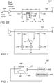
- Fig. 2A is a diagrammatic illustration of a microwave module 200 according to some embodiments of the invention.
- the module of Fig. 2A is similar to that of Fig. 1 , but includes four power meters: 210, 220, 230, and 240, assembled to the one or more PCBs that make module 200.
- the four measurement ports 110, 120, 130, and 140 couple the signals going through transmission line 108 to the four power meters 210, 220, 230, and 240, respectively.
- the measurement ports may be positioned so as to couple to the at least one power meter four different linear combinations of measured forward and backward signals.
- a forward signal is one that goes in transmission line 108 along a direction going from power amplifier 104 to antenna interface 106.
- the term "measured signal” is used to refer to the size of the signal as measured.
- the measurement device e.g., each of the power meters
- the measurement device may be influenced by signals additional to the one that the measurement device is supposed to measure, there may be room to calculate an actual signal, which is the forward signal that actually reached the antenna interface from the amplifier or the backward signal that actually emanated towards the amplifier from the antenna interface.
- 2A are: the forward signal to port 120; the backward signal coupled to port 130, a sum of the forward and backward signal is coupled to port 110, and a sum of the forward signal and 90 degrees shifted backwards signal, as summarized in Table 1, where F stands for forward; B for backwards, and j for the square root of -1.
- the parameters ⁇ and ⁇ are the coefficients in the linear combinations Table 1 Port Signal ⁇ ⁇ 110 F+B 1 1 120 F 1 0 130 B 0 1 140 F+jB 1 j
- Fig. 2B is a diagrammatic illustration of a microwave module 200B according to some embodiments of the invention.
- the module of Fig. 2B is similar to that of Fig. 1 , and includes four measurement ports 110, 120, 130, and 140, spaced away from each other so as to couple to the at least one power meter (not shown) different signals. However, none of the ports in Fig. 2B form together a bidirectional coupler.
- Port 120 is connected to a short conducting strip 125 parallel to transmission line 108. Strip 125 is terminated by a load 226.
- the measurement ports in Fig. 2B are positioned so as to couple to the at least one power meter four different linear combinations of measured forward and backward signals.
- the distances between port 110, 130, and 140 are ⁇ /6, and port 120 is between port 110 and port 130, for example, at a distance of ⁇ /12 from each of them.
- the measured signals coupled to the power meters in Fig. 2B are: the forward signal to port 120; and three different complex summations of the forward and backward signals to ports 110, 130, and 140.
- the signals coupled to the measurement ports in Fig. 2B are summarized in Table 1, where F stands for forward; B for backwards, and j for the square root of -1.
- the parameters ⁇ and ⁇ are the coefficients in the linear combinations Table 2 Port Signal ⁇ ⁇ 110 F+B 1 1 120 F 1 0 130 F + e j 2 ⁇ 3 B 1 e j 2 ⁇ 3 140 F + e j 4 ⁇ 3 B 1 e j 4 ⁇ 3
- the four different measurements may be useful for solving four linear equations for telling the real powers based on the measured ones.
- Such a set of four equations is developed, for example, below.
- M is a matrix that characterizes the module (e.g., module 200) and is independent on the signals. This is evident from the matrix M being related only to the parameters ⁇ i and ⁇ i of the six port coupler.
- the linear combinations (or, equivalently, the values for ⁇ i and ⁇ i ) are selected so as to control (e.g., minimize) the overall size of the module.
- the size of a module is the minimal total length of transmission lines needed in order to build it.
- a length is "minimal" if it does not include transmission line portions the lengths of which do not affect the functioning of the module.
- the size of the module is, under that definition, ⁇ / 8 , where ⁇ is the wavelength of the signals in the PCB.
- the module is designed to have a size of between about ⁇ /8 and about ⁇ /4.
- the module is designed to have a minimal possible size, e.g., by selecting positions to the measurement so as to minimize the size of the module.
- the four ports are arranged to allow transforming power levels measured by the at least one amplifier to actual power levels by a linear transformation (e.g., embodied in matrix M -1 above) having a condition number between 4 and 5.
- a linear transformation e.g., embodied in matrix M -1 above
- the solid state microwave module described herein may be included in a microwave oven, for example, for heating objects in the oven's cavity.
- the solid state amplifier is configured to output microwaves having power of at least 100W, for example, 100W, 150W, 200W, 500W, 1000W, 2000W, or any other power in between 100W and 2000 W.
- the solid state microwave module described herein may be used for sensing, for example, for sensing objects to be heated in a cavity.
- the heating itself may be carried out by microwave, convection, IR radiation, or any other heating method known in the art. Sensing may be achieved with much lower power levels than those required for heating.
- the solid state amplifier is configured to output microwaves having power of between 0.1mW and 100mW. Some possible powers include 0.1mW, 0.5mW, 1mW, 2mW, 10mW, 50mW, 100mW, or any other power in between.
- Fig. 3 is a diagrammatic illustration of a microwave module comprising one or more PCBs 302 according to some embodiments of the invention. While in Figure 2A , each port connects transmission line 108 to a corresponding voltmeter, in Fig. 3 , two ports (120 and 130) are connected to a single voltmeter 250 via switch 260, that has at least one state at which one of the ports is connected to the voltmeter and the other is disconnected from the voltmeter, and at least one state at which the other port is connected to the voltmeter, and the one of the ports is disconnected from the voltmeter. The two other ports (110 and 140) are connected each to a different (dedicated) voltmeter (210 and 240). In some embodiments, all the voltmeters are connected to the same ground.
- Fig. 4 is a diagrammatic representation of apparatus 400 for heating an object 402 in a heating cavity 401 by a heating unit 406.
- Apparatus 400 includes a solid state microwave module 500, processor 404, configured (e.g., by proper programming) to receive measurement results from module 500 and send control signals to heating unit 406 based on the received inputs.
- cavity 401 is a resonator, that resonates in one or more frequencies of microwaves supplied via module 500.
- the control signals sent to heating unit 406 based on the received inputs may include for example, at what power to heat, for how long, at what frequency (e.g., if heating unit 406 is a variable frequency microwave heater), etc..
- the processor may be configured to change the control signals based on changes in the measurements received from module 500.
- the measurements received from module 500 may be frequency dependent, and the measurements in the different frequencies may form a pattern (e.g., a pattern of scattering parameters vs. frequency).
- such patterns are identified in advance to be indicative to the object being heated and/or to a property of the object.
- a pattern recognition module in the processor may then recognize the pattern of the received measurements to match a pattern indicative of a certain object and/or property thereof, and send the control signals accordingly.
- the processor may receive (e.g., via a user interface) information regarding the object (e.g., that it is a frozen pizza), and use the measurements to tell a property of the object (e.g., that the frozen pizza is at a certain temperature, for example, -20°C, -4°C, etc.).
- module 500 provides microwave output at low power (e.g., between 0.0001W and 0.01W), and used only for sensing, in the sense of transmitting these low power microwave signals into cavity 101, receiving feedback from the cavity in the form of signals returning from the cavity to the module, and providing data indicative of said transmitting and receiving to the processor.
- the processor may process such data to identify, e.g., kind and/or property of the object in the cavity.
- Module 500 may include a solid state microwave power amplifier (e.g., 104) assembled to one or more PCBs.
- the solid state power amplifier is configured to be fed with RF signals having a variety of different frequencies, and amplify them.
- a six port coupler may be printed on the one or more PCBs, and this six port coupler may include one port connected to the power amplifier via a TEM or quasi-TEM transmission line.
- another one of the six ports of the coupler is connected to an antenna interface (106), e.g., via a TEM or quasi-TEM transmission line.
- the six port coupler may also include four measurement ports, each connected to a power meter, and the processor receives these measurements as inputs.
- module 500 is the same as described above, for example, the same as module 100, 200, or 300.
- the output of module 500 may be used for heating object 402.
- heating unit 406 is the same as module 500.
- module 500 is used for heating, and heating unit 406 is an additional heating unit.
- processor 404 is configured to process the measurement results using a non-iterative processing method to obtain processed results, and send the control signals based on the processed results.
- the non-iterative processing method may include, determining, based on the received measurement results, an actual power of the forward signal and an actual power of the backward signal by multiplying a predetermined 4 ⁇ 4 matrix by a measured 4 dimensional vector, each component of which is a result received from a respective one of the four ports.
- the predetermined matrix may characterize the six port coupler, for example, as the above-mentioned matrix M (or M -1 ) does.
- An example of the measured four dimensional vector may be the above-mentioned results vector P and matrix M -1 .
- other mathematical methods mathematically equivalent to such a multiplication of a result vector by a predetermined matrix may be similarly used.
- the processor may be configured to determine a property of the object being heated in the oven based on the received measurement results. For example, the frequency dependence of the return loss of the heating chamber with the object therein may be indicative to a property of the object, if, for example, the object itself is known, e.g., based on input received from a user.
- the return loss may be the real return loss, that is, the ratio between real forward and real backward signals.
- more than one module 500 is provided (e.g .
- two such modules may be used for evaluating, for example S parameters (e.g., a ratio between a real forward signal going out of an antenna of one module, and a real backward signal going into an antenna of another module at the same time and frequency, and when no module other than the first is outputting signals at that frequency).
- S parameters e.g., a ratio between a real forward signal going out of an antenna of one module, and a real backward signal going into an antenna of another module at the same time and frequency, and when no module other than the first is outputting signals at that frequency).
- heating unit 406 heats object 402 by microwaves, e.g., microwaves generated by a magnetron and/or by microwaves amplified by a solid state amplifier, e.g., the solid state amplifier of module 500.
- microwaves e.g., microwaves generated by a magnetron and/or by microwaves amplified by a solid state amplifier, e.g., the solid state amplifier of module 500.
- heating unit 406 heats object 402 by means other than microwave, e.g., blowing hot air into the cavity, radiating infrared radiation, etc..
- range format is merely for convenience and brevity and should not be construed as an inflexible limitation on the scope of descriptions of the present disclosure. Accordingly, the description of a range should be considered to have specifically disclosed all the possible subranges as well as individual numerical values within that range. For example, description of a range such as “from 1 to 6" should be considered to have specifically disclosed subranges such as “from 1 to 3", “from 1 to 4", “from 1 to 5", “from 2 to 4", “from 2 to 6", “from 3 to 6", etc.; as well as individual numbers within that range, for example, 1, 2, 3, 4, 5, and 6. This applies regardless of the breadth of the range.
Landscapes
- Physics & Mathematics (AREA)
- Electromagnetism (AREA)
- Control Of High-Frequency Heating Circuits (AREA)
- Constitution Of High-Frequency Heating (AREA)
Claims (15)
- Appareil (400) destiné à chauffer un objet (402) grâce à une unité de chauffage (406), l'appareil comprenant :un module micro-ondes à semi-conducteur (100, 200, 200B, 300, 500) comprenant une ou plusieurs cartes à circuit imprimé, PCB, (102, 302), dans lequel :
un amplificateur de puissance micro-ondes à semi-conducteur (104) est assemblé à ce ou à ces cartes PCB, et un coupleur à six ports est imprimé sur la ou les cartes PCB, un port du coupleur à six ports étant relié à l'amplificateur de puissance par l'intermédiaire d'une ligne de transmission à propagation TEM ou quasi TEM, etun processeur (404) configuré pour :recevoir des résultats de mesure en provenance d'au moins un compteur de puissance recevant des entrées en provenance de quatre ports du coupleur à six ports, etenvoyer des signaux de commande pour piloter l'unité de chauffage sur la base des résultats reçus. - Appareil (400) selon la revendication 1, dans lequel un port du coupleur à six ports est relié à une interface d'antenne (106) par l'intermédiaire d'une ligne de transmission à propagation TEM ou quasi TEM.
- Appareil (400) selon la revendication 2, comprenant en outre une antenne micro-ondes reliée à l'interface d'antenne (106) et configurée pour alimenter une cavité de chauffage (401) avec des micro-ondes.
- Appareil (400) selon l'une quelconque des revendications 1 à 3, dans lequel le processeur (404) est configuré pour :traiter les résultats de mesure en utilisant un procédé de traitement non itératif pour obtenir des résultats traités, etenvoyer les signaux de commande sur la base des résultats traités.
- Appareil selon l'une quelconque des revendications 1 à 4, dans lequel les quatre ports (110, 120, 130, 140) couplent à ce ou ces compteurs de puissance quatre combinaison linéaire différent de :un signal aller mesuré en provenance de l'amplificateur de puissance vers l'antenne, etun signal retour mesuré en provenance de l'antenne vers l'amplificateur de puissance.
- Appareil selon l'une quelconque des revendications 1 à 5, dans lequel :
le coupleur à six ports est agencé pour permettre la transformation de niveaux de puissance mesurés par le ou les compteurs de puissance en des niveaux réels de puissance grâce à une transformation linéaire présentant un nombre de condition compris entre 4 et 5, et/ou dans lequel :
la longueur totale du coupleur à six ports est comprise entre λ / 8 et λ / 4, λ représentant la longueur d'onde dans le vide d'un signal micro-ondes que l'amplificateur de puissance est configuré pour amplifier. - Appareil selon l'une quelconque des revendications 1 à 6, dans lequel le rapport entre l'amplitude des signaux aller et retour au niveau d'un port est différent du même rapport au niveau d'un ou de plusieurs des autres ports.
- Appareil selon l'une quelconque des revendications 1 à 7, dans lequel les quatre ports (110, 120, 130, 140) incluent :un premier port (120) couplant le signal aller mesuré au compteur de puissance,un deuxième port (130) couplant le signal retour mesuré au compteur de puissance,un troisième port (110) et un quatrième port (140) couplant chacun au compteur de puissance la sommation du signal aller mesuré et du signal retour mesuré, le quatrième port étant distant du troisième port de λ / 8, λ représentant la longueur d'onde dans le vide du signal aller.
- Appareil selon la revendication 8, dans lequel le premier port et le deuxième port forment ensemble un coupleur bidirectionnel.
- Appareil selon l'une quelconque des revendications 1 à 9, dans lequel au moins deux ports de comptage parmi les quatre ports de comptage (110, 120, 130, 140) sont reliés au même compteur de puissance, et dans lequel au moins deux des quatre ports sont connectés au même compteur de puissance par l'intermédiaire d'un interrupteur (260) assemblé à cette ou à ces cartes PCB, l'interrupteur connectant à chaque instant un seul des deux ports de comptage ou plus au même compteur de puissance.
- Appareil selon l'une quelconque des revendications 1 à 10, dans lequel le processeur (404) est configuré pour déterminer au moins l'un des critères suivants :sur la base des résultats de mesure reçus, la puissance réelle du signal aller et la puissance réelle du signal retour, dans lequel le processeur est configuré pour déterminer la puissance réelle des signaux aller et retour grâce à un procédé comprenant, ou bien équivalent mathématiquement à : la multiplication d'une matrice 4 X 4 prédéterminée par un vecteur à 4 dimensions mesuré, chaque composante étant le résultat reçu de l'un respectif des quatre ports,au moins une propriété de l'objet sur la base des résultats de mesure reçus, etsur la base des résultats de mesure reçus, le rapport entre la puissance du signal aller réel et la puissance du signal retour réel ainsi que la différence de phases entre le signal aller réel et le signal retour réel.
- Appareil selon l'une quelconque des revendications 1 à 11, dans lequel l'amplificateur de puissance à semi-conducteur (104) est configuré pour être alimenté par des signaux RF présentant diverses fréquences différentes, le processeur étant configuré pour déterminer, pour chacune des diverses fréquences différentes, des propriétés respectives qui peuvent être déduites de paramètres de diffusion de la cavité, et, en option, dans lequel le processeur est configuré pour sélectionner des fréquences sur la base des propriétés respectives déterminées pour celles-ci, et pour envoyer des signaux de commande afin de ne piloter qu'aux fréquences sélectionnées l'amplification de signaux RF par l'intermédiaire de l'amplificateur de puissance à semi-conducteur.
- Appareil selon l'une quelconque des revendications 1 à 12, dans lequel l'unité de chauffage est conçue pour chauffer l'objet par des micro-ondes, en option :l'unité de chauffage étant conçue pour chauffer l'objet par des micro-ondes générées par un magnétron, oul'unité de chauffage étant conçue pour chauffer l'objet par des micro-ondes amplifiées par l'amplificateur à semi-conducteur.
- Appareil selon la revendication 13, dans lequel l'unité de chauffage est conçue pour chauffer l'objet par des micro-ondes amplifiées par l'amplificateur à semi-conducteur, l'amplificateur à semi-conducteur délivrant des micro-ondes présentant une puissance d'au moins 100 W.
- Appareil selon l'une quelconque des revendications 1 à 14, dans lequel l'unité de chauffage est conçue pour chauffer l'objet grâce à un moyen différent des micro-ondes.
Applications Claiming Priority (2)
| Application Number | Priority Date | Filing Date | Title |
|---|---|---|---|
| US201762545608P | 2017-08-15 | 2017-08-15 | |
| PCT/IL2018/050903 WO2019035130A1 (fr) | 2017-08-15 | 2018-08-14 | Mesures de puissance à six ports |
Publications (2)
| Publication Number | Publication Date |
|---|---|
| EP3669614A1 EP3669614A1 (fr) | 2020-06-24 |
| EP3669614B1 true EP3669614B1 (fr) | 2022-03-09 |
Family
ID=63407495
Family Applications (1)
| Application Number | Title | Priority Date | Filing Date |
|---|---|---|---|
| EP18765200.3A Not-in-force EP3669614B1 (fr) | 2017-08-15 | 2018-08-14 | Mesures de puissance à six ports |
Country Status (4)
| Country | Link |
|---|---|
| US (2) | US20200281051A1 (fr) |
| EP (1) | EP3669614B1 (fr) |
| CN (2) | CN111201835A (fr) |
| WO (2) | WO2019035130A1 (fr) |
Families Citing this family (6)
| Publication number | Priority date | Publication date | Assignee | Title |
|---|---|---|---|---|
| WO2020202109A1 (fr) * | 2019-04-05 | 2020-10-08 | Pyrowave Inc. | Syntoniseur d'impédance à refroidissement interne pour systèmes de pyrolyse à micro-ondes |
| CN110024843B (zh) * | 2019-05-21 | 2025-01-03 | 中国海洋大学 | 433MHz加热腔腔体及固态源工业化解冻设备 |
| CN112803158B (zh) * | 2019-11-14 | 2022-06-28 | 华为技术有限公司 | 一种电子设备 |
| KR20210136717A (ko) * | 2020-05-08 | 2021-11-17 | 엘지전자 주식회사 | 복수 개의 안테나를 갖는 오븐 |
| CN114340072B (zh) * | 2021-12-22 | 2024-12-10 | 广东美的白色家电技术创新中心有限公司 | 一种微波炉用天线装置及微波炉 |
| JP7429380B1 (ja) * | 2022-07-05 | 2024-02-08 | 株式会社ダイレクト・アール・エフ | 加熱調理器 |
Family Cites Families (66)
| Publication number | Priority date | Publication date | Assignee | Title |
|---|---|---|---|---|
| US3192642A (en) * | 1961-11-06 | 1965-07-06 | Gen Electric | Automatic fabric drying machine and control means |
| US3439431A (en) * | 1967-12-15 | 1969-04-22 | Gen Electric | Microwave dryer control circuit |
| US4297557A (en) * | 1976-05-03 | 1981-10-27 | Robertshaw Controls Company | Microwave oven temperature indicator and control means |
| CA1081796A (fr) * | 1978-02-09 | 1980-07-15 | Canadian Patents And Development Limited | Fours a micro-ondes a chauffage controle utilisant differentes frequences de travail |
| JPS54134479A (en) * | 1978-04-10 | 1979-10-18 | Sharp Corp | Wireless temperature measuring device |
| US4340796A (en) * | 1978-08-31 | 1982-07-20 | Sharp Kabushiki Kaisha | Wireless temperature-sensing system inclusive of thermally-responsive oscillator |
| US4210795A (en) * | 1978-11-30 | 1980-07-01 | Litton Systems, Inc. | System and method for regulating power output in a microwave oven |
| JPS55111091A (en) * | 1979-02-19 | 1980-08-27 | Sanyo Electric Co | Cooking oven |
| US4447693A (en) * | 1979-09-06 | 1984-05-08 | Litton Systems, Inc. | Power controlled microwave oven |
| JPS5688294A (en) * | 1979-12-21 | 1981-07-17 | Tokyo Shibaura Electric Co | Electronic range |
| US4714812A (en) * | 1985-05-08 | 1987-12-22 | John F. Woodhead, III | Apparatus and method for processing dielectric materials with microwave energy |
| US5616268A (en) * | 1994-07-07 | 1997-04-01 | Microwave Medical Systems | Microwave blood thawing with feedback control |
| US6210367B1 (en) * | 1995-09-06 | 2001-04-03 | Microwave Medical Systems, Inc. | Intracorporeal microwave warming method and apparatus |
| JP3380685B2 (ja) * | 1996-07-12 | 2003-02-24 | アルプス電気株式会社 | 高周波電子機器 |
| WO2000003564A1 (fr) * | 1998-07-08 | 2000-01-20 | Matsushita Electric Industrial Co., Ltd. | Unite a impedance variable, dispositif l'utilisant, et four a micro-ondes |
| US6222170B1 (en) * | 1999-08-24 | 2001-04-24 | Ut-Battelle, Llc | Apparatus and method for microwave processing of materials using field-perturbing tool |
| US7722248B1 (en) * | 1999-09-20 | 2010-05-25 | Maverick Industries, Inc. | Wireless remote cooking thermometer system |
| DE10005146A1 (de) * | 2000-02-04 | 2001-08-09 | Widia Gmbh | Vorrichtung zur Einstellung einer Mikrowellen-Energiedichteverteilung in einem Applikator und Verwendung dieser Vorrichtung |
| RU2263420C2 (ru) * | 2000-02-25 | 2005-10-27 | Персонал Кемистри И Уппсала Аб | Микроволновое устройство нагревания |
| SE521313C2 (sv) * | 2000-09-15 | 2003-10-21 | Whirlpool Co | Mikrovågsugn samt förfarande vid sådan |
| ATE379958T1 (de) * | 2001-07-26 | 2007-12-15 | Siemens Spa Italiana | Leiterplatte und entsprechendes herstellungsverfahren zur installation von mikrowellenchips bis zu 80 ghz |
| US7133739B2 (en) * | 2001-11-01 | 2006-11-07 | Salton, Inc. | Intelligent microwave oven |
| EP1506595A4 (fr) * | 2002-04-19 | 2005-07-27 | Roadeye Flr General Partnershi | Concept de systeme rf pour radar de vehicules comprenant plusieurs faisceaux |
| US20040206755A1 (en) * | 2003-04-18 | 2004-10-21 | Hadinger Peter James | Microwave heating using distributed semiconductor sources |
| JP2006525738A (ja) * | 2003-05-08 | 2006-11-09 | コーニンクレッカ フィリップス エレクトロニクス エヌ ヴィ | 電子回路における無線周波信号の分散 |
| US7498549B2 (en) * | 2003-10-24 | 2009-03-03 | Raytheon Company | Selective layer millimeter-wave surface-heating system and method |
| WO2005069883A2 (fr) * | 2004-01-15 | 2005-08-04 | Bae Systems Information And Electronic Systems Integration Inc. | Procede et appareil pour la verification de ligne de transmission et de guide d'onde |
| JP5179382B2 (ja) * | 2006-02-21 | 2013-04-10 | ゴジ リミテッド | 電磁加熱 |
| US10674570B2 (en) * | 2006-02-21 | 2020-06-02 | Goji Limited | System and method for applying electromagnetic energy |
| US8839527B2 (en) * | 2006-02-21 | 2014-09-23 | Goji Limited | Drying apparatus and methods and accessories for use therewith |
| US7520667B2 (en) * | 2006-05-11 | 2009-04-21 | John Bean Technologies Ab | Method and system for determining process parameters |
| ES2444222T3 (es) * | 2006-07-10 | 2014-02-24 | Goji Limited | Preparación de alimentos |
| JP4860395B2 (ja) * | 2006-07-28 | 2012-01-25 | パナソニック株式会社 | マイクロ波処理装置およびマイクロ波処理方法 |
| US20090188396A1 (en) * | 2007-08-06 | 2009-07-30 | Hofmann Matthias C | Oven with wireless temperature sensor for use in monitoring food temperature |
| US9131543B2 (en) * | 2007-08-30 | 2015-09-08 | Goji Limited | Dynamic impedance matching in RF resonator cavity |
| DE202007019030U1 (de) * | 2007-09-19 | 2010-04-15 | Neue Materialien Bayreuth Gmbh | Hybridofen |
| US20090321429A1 (en) * | 2008-06-30 | 2009-12-31 | Hyde Roderick A | Microwave oven |
| US8927913B2 (en) * | 2008-06-30 | 2015-01-06 | The Invention Science Fund I, Llc | Microwave processing systems and methods |
| US20160073453A1 (en) * | 2008-06-30 | 2016-03-10 | Searete Llc | Microwave oven |
| FI122204B (fi) * | 2008-09-11 | 2011-10-14 | Raute Oyj | Laite tasomaisten tuotteiden mikroaaltolämmitystä varten |
| KR101569235B1 (ko) * | 2008-11-10 | 2015-11-13 | 고지 엘티디. | Rf 에너지를 사용하여 가열하는 장치 및 방법 |
| DE102008064259A1 (de) | 2008-12-20 | 2010-07-01 | Festo Ag & Co. Kg | Fluidischer Zylinder mit einer Mikrowellen-Messanordnung und Verfahren zur Erfassung wenigstens eines Parameters |
| WO2010104569A1 (fr) * | 2009-03-09 | 2010-09-16 | Neurds Inc. | Système et procédé pour le transfert d'énergie sans fil dans des dispositifs médicaux aptes à être implantés |
| US9300046B2 (en) * | 2009-03-09 | 2016-03-29 | Nucurrent, Inc. | Method for manufacture of multi-layer-multi-turn high efficiency inductors |
| US20100320189A1 (en) * | 2009-06-18 | 2010-12-23 | Buchheit Brian K | Automated user-customized cooking appliance configuration |
| US9398646B2 (en) * | 2009-07-10 | 2016-07-19 | Panasonic Intellectual Property Management Co., Ltd. | Microwave heating device and microwave heating control method |
| US9462635B2 (en) * | 2009-11-10 | 2016-10-04 | Goji Limited | Device and method for heating using RF energy |
| MX2012012706A (es) * | 2010-05-03 | 2013-04-29 | Goji Ltd | Analisis modal. |
| US8348504B2 (en) * | 2010-05-12 | 2013-01-08 | Wireless Sensor Technologies, Llc | Wireless temperature measurement system and methods of making and using same |
| KR101752523B1 (ko) * | 2010-07-01 | 2017-06-29 | 고지 엘티디. | 무선 주파수 에너지에 의한 대상물 처리 |
| EP2445312B1 (fr) * | 2010-10-22 | 2017-02-22 | Whirlpool Corporation | Appareil de chauffage par micro-ondes et son procédé de fonctionnement |
| US9992824B2 (en) * | 2010-10-29 | 2018-06-05 | Goji Limited | Time estimation for energy application in an RF energy transfer device |
| US20120164022A1 (en) * | 2010-12-22 | 2012-06-28 | Goji Limited | Methods and devices for processing objects by applying electromagnetic (em) energy |
| US9414444B2 (en) * | 2011-02-11 | 2016-08-09 | Goji Ltd. | Interface for controlling energy application apparatus |
| WO2013021280A2 (fr) * | 2011-08-11 | 2013-02-14 | Goji Ltd. | Application de fréquences radioélectriques en l'absence de rétro-information |
| US20130080098A1 (en) * | 2011-08-31 | 2013-03-28 | Goji, Ltd. | Object Processing State Sensing Using RF Radiation |
| US9161390B2 (en) * | 2012-02-06 | 2015-10-13 | Goji Limited | Methods and devices for applying RF energy according to energy application schedules |
| EP2815405B1 (fr) * | 2012-02-14 | 2018-01-10 | Goji Limited | Dispositif d'application d'énergie rf à une cavité |
| US9804104B2 (en) * | 2012-03-19 | 2017-10-31 | Goji Limited | Applying RF energy according to time variations in EM feedback |
| EP2831604B1 (fr) * | 2012-03-31 | 2019-10-16 | Microcube, LLC | Puissance renvoyée pour applications micro-ondes |
| CN203481385U (zh) * | 2013-09-27 | 2014-03-12 | 佛山市蓝波湾通讯设备有限公司 | 一种阵列天线 |
| US10244585B2 (en) * | 2013-10-07 | 2019-03-26 | Goji Limited | Apparatus and method for sensing and processing by RF |
| US20150136760A1 (en) * | 2013-11-15 | 2015-05-21 | Stmicroelectronics (Canada), Inc. | Microwave oven using solid state amplifiers and antenna array |
| CN104470183B (zh) * | 2014-12-04 | 2017-11-21 | 浙江全世科技有限公司 | 可自调谐的磁控管微波源mpt、自调谐装置及控制方法 |
| JP7027891B2 (ja) * | 2015-06-03 | 2022-03-02 | ワールプール コーポレイション | 電磁調理のための方法および装置 |
| US10148016B2 (en) * | 2015-07-14 | 2018-12-04 | At&T Intellectual Property I, L.P. | Apparatus and methods for communicating utilizing an antenna array |
-
2018
- 2018-08-14 EP EP18765200.3A patent/EP3669614B1/fr not_active Not-in-force
- 2018-08-14 CN CN201880066264.3A patent/CN111201835A/zh active Pending
- 2018-08-14 CN CN201880067137.5A patent/CN111213433A/zh active Pending
- 2018-08-14 WO PCT/IL2018/050903 patent/WO2019035130A1/fr not_active Ceased
- 2018-08-14 WO PCT/IL2018/050902 patent/WO2019035129A1/fr not_active Ceased
- 2018-08-14 US US16/647,737 patent/US20200281051A1/en not_active Abandoned
- 2018-08-14 US US16/634,728 patent/US20200205248A1/en not_active Abandoned
Also Published As
| Publication number | Publication date |
|---|---|
| WO2019035130A1 (fr) | 2019-02-21 |
| CN111201835A (zh) | 2020-05-26 |
| WO2019035129A1 (fr) | 2019-02-21 |
| CN111213433A (zh) | 2020-05-29 |
| EP3669614A1 (fr) | 2020-06-24 |
| US20200281051A1 (en) | 2020-09-03 |
| US20200205248A1 (en) | 2020-06-25 |
Similar Documents
| Publication | Publication Date | Title |
|---|---|---|
| EP3669614B1 (fr) | Mesures de puissance à six ports | |
| EP3305019B1 (fr) | Procédé et dispositif de cuisson électromagnétique | |
| US11330680B2 (en) | Calibration of an RF processing system | |
| Zhou et al. | Heating performance of microwave ovens powered by magnetron and solid-state generators | |
| US10470255B2 (en) | RF energy application based on electromagnetic feedback | |
| EP2425794B1 (fr) | Réseau d'applicateurs de champ magnétique doté de capteurs de champ intégrés pour la correction implicite du couplage réciproque et de la désadaptation | |
| EP3462818A1 (fr) | Procédé et dispositif de cuisson électromagnétique utilisant une stratégie de détection asynchrone pour le suivi en temps réel de modes résonants | |
| Chakarothai et al. | Dosimetry of a reverberation chamber for whole-body exposure of small animals | |
| Raaijmakers et al. | An MR-compatible antenna and application in a murine superficial hyperthermia applicator | |
| US20110279334A1 (en) | Resonant Cavity Injection-Based Calibration of a Radiant Energy Device | |
| EP3563091A1 (fr) | Nano-refroidissement dans des fours à micro-ondes de cuisson à l'état solide | |
| TWI429921B (zh) | 用以將介電損耗正切特徵化之方法 | |
| US11051371B2 (en) | Method and device for electromagnetic cooking using closed loop control | |
| Brunetti et al. | Comparison among coaxial microcalorimeter models | |
| CN109691227A (zh) | 诊断电磁烹饪装置的方法 | |
| Xiong et al. | Experimental comparison between two different radio-frequency delivery methods | |
| Frabetti et al. | Modelling a single-mode 915 MHz microwave applicator for low-moisture food treatment: comparison between COMSOL Multiphysics® and CST Studio Suite® | |
| Kubiczek et al. | Calorimetric Thermal Voltage Converter with a Microwave Disc Resistor as a Heater | |
| Evseev et al. | Measurement of Intrinsic Parameters of Electronic Components in Strip-Line Transmission Line by Analyzer P4226 | |
| Li et al. | Passive Intermodulation Model Based on Conductors Cross-Section for Printed Transmission Line | |
| Vasileva et al. | Modelingand Creation of a Reference Installation for the Reproduction of the Electromagnetic Field Strength Unit on the Basis of a GTEM–Cell in he Range of Frequency up to 1 GHz | |
| Stolyarov | Matching the microwave-oven chamber to the magnetron | |
| Ezanuddin et al. | A Design Method of Metasurface using CCSR | |
| Paffi et al. | An over-moded TEM Cell system for in vivo exposure at 2.45 GHz | |
| CN119849170A (zh) | 一种电场辐射敏感度的仿真测试方法及系统 |
Legal Events
| Date | Code | Title | Description |
|---|---|---|---|
| STAA | Information on the status of an ep patent application or granted ep patent |
Free format text: STATUS: UNKNOWN |
|
| STAA | Information on the status of an ep patent application or granted ep patent |
Free format text: STATUS: THE INTERNATIONAL PUBLICATION HAS BEEN MADE |
|
| PUAI | Public reference made under article 153(3) epc to a published international application that has entered the european phase |
Free format text: ORIGINAL CODE: 0009012 |
|
| STAA | Information on the status of an ep patent application or granted ep patent |
Free format text: STATUS: REQUEST FOR EXAMINATION WAS MADE |
|
| 17P | Request for examination filed |
Effective date: 20200316 |
|
| AK | Designated contracting states |
Kind code of ref document: A1 Designated state(s): AL AT BE BG CH CY CZ DE DK EE ES FI FR GB GR HR HU IE IS IT LI LT LU LV MC MK MT NL NO PL PT RO RS SE SI SK SM TR |
|
| AX | Request for extension of the european patent |
Extension state: BA ME |
|
| DAV | Request for validation of the european patent (deleted) | ||
| DAX | Request for extension of the european patent (deleted) | ||
| GRAP | Despatch of communication of intention to grant a patent |
Free format text: ORIGINAL CODE: EPIDOSNIGR1 |
|
| STAA | Information on the status of an ep patent application or granted ep patent |
Free format text: STATUS: GRANT OF PATENT IS INTENDED |
|
| INTG | Intention to grant announced |
Effective date: 20211019 |
|
| GRAS | Grant fee paid |
Free format text: ORIGINAL CODE: EPIDOSNIGR3 |
|
| GRAA | (expected) grant |
Free format text: ORIGINAL CODE: 0009210 |
|
| STAA | Information on the status of an ep patent application or granted ep patent |
Free format text: STATUS: THE PATENT HAS BEEN GRANTED |
|
| AK | Designated contracting states |
Kind code of ref document: B1 Designated state(s): AL AT BE BG CH CY CZ DE DK EE ES FI FR GB GR HR HU IE IS IT LI LT LU LV MC MK MT NL NO PL PT RO RS SE SI SK SM TR |
|
| REG | Reference to a national code |
Ref country code: CH Ref legal event code: EP Ref country code: AT Ref legal event code: REF Ref document number: 1475211 Country of ref document: AT Kind code of ref document: T Effective date: 20220315 |
|
| REG | Reference to a national code |
Ref country code: IE Ref legal event code: FG4D |
|
| REG | Reference to a national code |
Ref country code: DE Ref legal event code: R096 Ref document number: 602018032032 Country of ref document: DE |
|
| REG | Reference to a national code |
Ref country code: LT Ref legal event code: MG9D |
|
| REG | Reference to a national code |
Ref country code: NL Ref legal event code: MP Effective date: 20220309 |
|
| PG25 | Lapsed in a contracting state [announced via postgrant information from national office to epo] |
Ref country code: SE Free format text: LAPSE BECAUSE OF FAILURE TO SUBMIT A TRANSLATION OF THE DESCRIPTION OR TO PAY THE FEE WITHIN THE PRESCRIBED TIME-LIMIT Effective date: 20220309 Ref country code: RS Free format text: LAPSE BECAUSE OF FAILURE TO SUBMIT A TRANSLATION OF THE DESCRIPTION OR TO PAY THE FEE WITHIN THE PRESCRIBED TIME-LIMIT Effective date: 20220309 Ref country code: NO Free format text: LAPSE BECAUSE OF FAILURE TO SUBMIT A TRANSLATION OF THE DESCRIPTION OR TO PAY THE FEE WITHIN THE PRESCRIBED TIME-LIMIT Effective date: 20220609 Ref country code: LT Free format text: LAPSE BECAUSE OF FAILURE TO SUBMIT A TRANSLATION OF THE DESCRIPTION OR TO PAY THE FEE WITHIN THE PRESCRIBED TIME-LIMIT Effective date: 20220309 Ref country code: HR Free format text: LAPSE BECAUSE OF FAILURE TO SUBMIT A TRANSLATION OF THE DESCRIPTION OR TO PAY THE FEE WITHIN THE PRESCRIBED TIME-LIMIT Effective date: 20220309 Ref country code: BG Free format text: LAPSE BECAUSE OF FAILURE TO SUBMIT A TRANSLATION OF THE DESCRIPTION OR TO PAY THE FEE WITHIN THE PRESCRIBED TIME-LIMIT Effective date: 20220609 |
|
| REG | Reference to a national code |
Ref country code: AT Ref legal event code: MK05 Ref document number: 1475211 Country of ref document: AT Kind code of ref document: T Effective date: 20220309 |
|
| PG25 | Lapsed in a contracting state [announced via postgrant information from national office to epo] |
Ref country code: LV Free format text: LAPSE BECAUSE OF FAILURE TO SUBMIT A TRANSLATION OF THE DESCRIPTION OR TO PAY THE FEE WITHIN THE PRESCRIBED TIME-LIMIT Effective date: 20220309 Ref country code: GR Free format text: LAPSE BECAUSE OF FAILURE TO SUBMIT A TRANSLATION OF THE DESCRIPTION OR TO PAY THE FEE WITHIN THE PRESCRIBED TIME-LIMIT Effective date: 20220610 Ref country code: FI Free format text: LAPSE BECAUSE OF FAILURE TO SUBMIT A TRANSLATION OF THE DESCRIPTION OR TO PAY THE FEE WITHIN THE PRESCRIBED TIME-LIMIT Effective date: 20220309 |
|
| PG25 | Lapsed in a contracting state [announced via postgrant information from national office to epo] |
Ref country code: NL Free format text: LAPSE BECAUSE OF FAILURE TO SUBMIT A TRANSLATION OF THE DESCRIPTION OR TO PAY THE FEE WITHIN THE PRESCRIBED TIME-LIMIT Effective date: 20220309 |
|
| PG25 | Lapsed in a contracting state [announced via postgrant information from national office to epo] |
Ref country code: SM Free format text: LAPSE BECAUSE OF FAILURE TO SUBMIT A TRANSLATION OF THE DESCRIPTION OR TO PAY THE FEE WITHIN THE PRESCRIBED TIME-LIMIT Effective date: 20220309 Ref country code: SK Free format text: LAPSE BECAUSE OF FAILURE TO SUBMIT A TRANSLATION OF THE DESCRIPTION OR TO PAY THE FEE WITHIN THE PRESCRIBED TIME-LIMIT Effective date: 20220309 Ref country code: RO Free format text: LAPSE BECAUSE OF FAILURE TO SUBMIT A TRANSLATION OF THE DESCRIPTION OR TO PAY THE FEE WITHIN THE PRESCRIBED TIME-LIMIT Effective date: 20220309 Ref country code: PT Free format text: LAPSE BECAUSE OF FAILURE TO SUBMIT A TRANSLATION OF THE DESCRIPTION OR TO PAY THE FEE WITHIN THE PRESCRIBED TIME-LIMIT Effective date: 20220711 Ref country code: ES Free format text: LAPSE BECAUSE OF FAILURE TO SUBMIT A TRANSLATION OF THE DESCRIPTION OR TO PAY THE FEE WITHIN THE PRESCRIBED TIME-LIMIT Effective date: 20220309 Ref country code: EE Free format text: LAPSE BECAUSE OF FAILURE TO SUBMIT A TRANSLATION OF THE DESCRIPTION OR TO PAY THE FEE WITHIN THE PRESCRIBED TIME-LIMIT Effective date: 20220309 Ref country code: CZ Free format text: LAPSE BECAUSE OF FAILURE TO SUBMIT A TRANSLATION OF THE DESCRIPTION OR TO PAY THE FEE WITHIN THE PRESCRIBED TIME-LIMIT Effective date: 20220309 Ref country code: AT Free format text: LAPSE BECAUSE OF FAILURE TO SUBMIT A TRANSLATION OF THE DESCRIPTION OR TO PAY THE FEE WITHIN THE PRESCRIBED TIME-LIMIT Effective date: 20220309 |
|
| PG25 | Lapsed in a contracting state [announced via postgrant information from national office to epo] |
Ref country code: PL Free format text: LAPSE BECAUSE OF FAILURE TO SUBMIT A TRANSLATION OF THE DESCRIPTION OR TO PAY THE FEE WITHIN THE PRESCRIBED TIME-LIMIT Effective date: 20220309 Ref country code: IS Free format text: LAPSE BECAUSE OF FAILURE TO SUBMIT A TRANSLATION OF THE DESCRIPTION OR TO PAY THE FEE WITHIN THE PRESCRIBED TIME-LIMIT Effective date: 20220709 Ref country code: AL Free format text: LAPSE BECAUSE OF FAILURE TO SUBMIT A TRANSLATION OF THE DESCRIPTION OR TO PAY THE FEE WITHIN THE PRESCRIBED TIME-LIMIT Effective date: 20220309 |
|
| REG | Reference to a national code |
Ref country code: DE Ref legal event code: R097 Ref document number: 602018032032 Country of ref document: DE |
|
| PLBE | No opposition filed within time limit |
Free format text: ORIGINAL CODE: 0009261 |
|
| STAA | Information on the status of an ep patent application or granted ep patent |
Free format text: STATUS: NO OPPOSITION FILED WITHIN TIME LIMIT |
|
| PG25 | Lapsed in a contracting state [announced via postgrant information from national office to epo] |
Ref country code: DK Free format text: LAPSE BECAUSE OF FAILURE TO SUBMIT A TRANSLATION OF THE DESCRIPTION OR TO PAY THE FEE WITHIN THE PRESCRIBED TIME-LIMIT Effective date: 20220309 |
|
| REG | Reference to a national code |
Ref country code: DE Ref legal event code: R081 Ref document number: 602018032032 Country of ref document: DE Owner name: JOLIET 2010 LIMITED, VG Free format text: FORMER OWNER: GOJI LIMITED, HAMILTON, BM |
|
| 26N | No opposition filed |
Effective date: 20221212 |
|
| PG25 | Lapsed in a contracting state [announced via postgrant information from national office to epo] |
Ref country code: SI Free format text: LAPSE BECAUSE OF FAILURE TO SUBMIT A TRANSLATION OF THE DESCRIPTION OR TO PAY THE FEE WITHIN THE PRESCRIBED TIME-LIMIT Effective date: 20220309 |
|
| REG | Reference to a national code |
Ref country code: GB Ref legal event code: 732E Free format text: REGISTERED BETWEEN 20230209 AND 20230215 |
|
| PG25 | Lapsed in a contracting state [announced via postgrant information from national office to epo] |
Ref country code: MC Free format text: LAPSE BECAUSE OF FAILURE TO SUBMIT A TRANSLATION OF THE DESCRIPTION OR TO PAY THE FEE WITHIN THE PRESCRIBED TIME-LIMIT Effective date: 20220309 |
|
| REG | Reference to a national code |
Ref country code: CH Ref legal event code: PL |
|
| PG25 | Lapsed in a contracting state [announced via postgrant information from national office to epo] |
Ref country code: LU Free format text: LAPSE BECAUSE OF NON-PAYMENT OF DUE FEES Effective date: 20220814 Ref country code: LI Free format text: LAPSE BECAUSE OF NON-PAYMENT OF DUE FEES Effective date: 20220831 Ref country code: CH Free format text: LAPSE BECAUSE OF NON-PAYMENT OF DUE FEES Effective date: 20220831 |
|
| REG | Reference to a national code |
Ref country code: BE Ref legal event code: MM Effective date: 20220831 |
|
| P01 | Opt-out of the competence of the unified patent court (upc) registered |
Effective date: 20230516 |
|
| PG25 | Lapsed in a contracting state [announced via postgrant information from national office to epo] |
Ref country code: IT Free format text: LAPSE BECAUSE OF FAILURE TO SUBMIT A TRANSLATION OF THE DESCRIPTION OR TO PAY THE FEE WITHIN THE PRESCRIBED TIME-LIMIT Effective date: 20220309 Ref country code: IE Free format text: LAPSE BECAUSE OF NON-PAYMENT OF DUE FEES Effective date: 20220814 Ref country code: FR Free format text: LAPSE BECAUSE OF NON-PAYMENT OF DUE FEES Effective date: 20220831 |
|
| PG25 | Lapsed in a contracting state [announced via postgrant information from national office to epo] |
Ref country code: BE Free format text: LAPSE BECAUSE OF NON-PAYMENT OF DUE FEES Effective date: 20220831 |
|
| PGFP | Annual fee paid to national office [announced via postgrant information from national office to epo] |
Ref country code: GB Payment date: 20230822 Year of fee payment: 6 |
|
| PGFP | Annual fee paid to national office [announced via postgrant information from national office to epo] |
Ref country code: DE Payment date: 20230821 Year of fee payment: 6 |
|
| PG25 | Lapsed in a contracting state [announced via postgrant information from national office to epo] |
Ref country code: CY Free format text: LAPSE BECAUSE OF FAILURE TO SUBMIT A TRANSLATION OF THE DESCRIPTION OR TO PAY THE FEE WITHIN THE PRESCRIBED TIME-LIMIT Effective date: 20220309 |
|
| PG25 | Lapsed in a contracting state [announced via postgrant information from national office to epo] |
Ref country code: MK Free format text: LAPSE BECAUSE OF FAILURE TO SUBMIT A TRANSLATION OF THE DESCRIPTION OR TO PAY THE FEE WITHIN THE PRESCRIBED TIME-LIMIT Effective date: 20220309 Ref country code: HU Free format text: LAPSE BECAUSE OF FAILURE TO SUBMIT A TRANSLATION OF THE DESCRIPTION OR TO PAY THE FEE WITHIN THE PRESCRIBED TIME-LIMIT; INVALID AB INITIO Effective date: 20180814 |
|
| PG25 | Lapsed in a contracting state [announced via postgrant information from national office to epo] |
Ref country code: MT Free format text: LAPSE BECAUSE OF FAILURE TO SUBMIT A TRANSLATION OF THE DESCRIPTION OR TO PAY THE FEE WITHIN THE PRESCRIBED TIME-LIMIT Effective date: 20220309 |
|
| REG | Reference to a national code |
Ref country code: DE Ref legal event code: R119 Ref document number: 602018032032 Country of ref document: DE |
|
| GBPC | Gb: european patent ceased through non-payment of renewal fee |
Effective date: 20240814 |
|
| PG25 | Lapsed in a contracting state [announced via postgrant information from national office to epo] |
Ref country code: DE Free format text: LAPSE BECAUSE OF NON-PAYMENT OF DUE FEES Effective date: 20250301 |
|
| PG25 | Lapsed in a contracting state [announced via postgrant information from national office to epo] |
Ref country code: GB Free format text: LAPSE BECAUSE OF NON-PAYMENT OF DUE FEES Effective date: 20240814 |
|
| PG25 | Lapsed in a contracting state [announced via postgrant information from national office to epo] |
Ref country code: TR Free format text: LAPSE BECAUSE OF FAILURE TO SUBMIT A TRANSLATION OF THE DESCRIPTION OR TO PAY THE FEE WITHIN THE PRESCRIBED TIME-LIMIT Effective date: 20220309 |