EP3669697A1 - Versiegelbares, intern zugeführtes applikatorsystem - Google Patents
Versiegelbares, intern zugeführtes applikatorsystem Download PDFInfo
- Publication number
- EP3669697A1 EP3669697A1 EP18213658.0A EP18213658A EP3669697A1 EP 3669697 A1 EP3669697 A1 EP 3669697A1 EP 18213658 A EP18213658 A EP 18213658A EP 3669697 A1 EP3669697 A1 EP 3669697A1
- Authority
- EP
- European Patent Office
- Prior art keywords
- applicator
- valve body
- substances
- duct
- applicator system
- Prior art date
- Legal status (The legal status is an assumption and is not a legal conclusion. Google has not performed a legal analysis and makes no representation as to the accuracy of the status listed.)
- Withdrawn
Links
- 239000000126 substance Substances 0.000 claims abstract description 75
- 230000003068 static effect Effects 0.000 claims abstract description 14
- 239000002537 cosmetic Substances 0.000 claims abstract description 8
- 230000009969 flowable effect Effects 0.000 claims abstract description 6
- 230000008878 coupling Effects 0.000 claims description 13
- 238000010168 coupling process Methods 0.000 claims description 13
- 238000005859 coupling reaction Methods 0.000 claims description 13
- 239000000203 mixture Substances 0.000 claims description 8
- 239000000835 fiber Substances 0.000 claims description 3
- 230000007480 spreading Effects 0.000 claims description 2
- 238000003892 spreading Methods 0.000 claims description 2
- 230000000063 preceeding effect Effects 0.000 claims 1
- 238000013461 design Methods 0.000 description 9
- 238000002156 mixing Methods 0.000 description 7
- 239000000344 soap Substances 0.000 description 7
- 230000003993 interaction Effects 0.000 description 6
- 239000000243 solution Substances 0.000 description 4
- 238000004891 communication Methods 0.000 description 3
- 230000000295 complement effect Effects 0.000 description 3
- 230000001627 detrimental effect Effects 0.000 description 3
- 210000004209 hair Anatomy 0.000 description 3
- 239000012080 ambient air Substances 0.000 description 2
- 230000008901 benefit Effects 0.000 description 2
- 238000010276 construction Methods 0.000 description 2
- 230000000694 effects Effects 0.000 description 2
- 238000001746 injection moulding Methods 0.000 description 2
- 239000000463 material Substances 0.000 description 2
- 230000007246 mechanism Effects 0.000 description 2
- 238000011144 upstream manufacturing Methods 0.000 description 2
- LFQSCWFLJHTTHZ-UHFFFAOYSA-N Ethanol Chemical compound CCO LFQSCWFLJHTTHZ-UHFFFAOYSA-N 0.000 description 1
- 230000003139 buffering effect Effects 0.000 description 1
- 230000008859 change Effects 0.000 description 1
- 238000006243 chemical reaction Methods 0.000 description 1
- 230000006835 compression Effects 0.000 description 1
- 238000007906 compression Methods 0.000 description 1
- 230000001808 coupling effect Effects 0.000 description 1
- 238000009826 distribution Methods 0.000 description 1
- 238000000605 extraction Methods 0.000 description 1
- 239000012530 fluid Substances 0.000 description 1
- 230000006872 improvement Effects 0.000 description 1
- 230000010354 integration Effects 0.000 description 1
- 238000000034 method Methods 0.000 description 1
- 229920001296 polysiloxane Polymers 0.000 description 1
- 238000002360 preparation method Methods 0.000 description 1
- 238000003825 pressing Methods 0.000 description 1
- 230000037452 priming Effects 0.000 description 1
- 230000008569 process Effects 0.000 description 1
- 238000012552 review Methods 0.000 description 1
- 238000003860 storage Methods 0.000 description 1
- 238000012546 transfer Methods 0.000 description 1
- 239000011345 viscous material Substances 0.000 description 1
- XLYOFNOQVPJJNP-UHFFFAOYSA-N water Substances O XLYOFNOQVPJJNP-UHFFFAOYSA-N 0.000 description 1
Images



Classifications
-
- A—HUMAN NECESSITIES
- A45—HAND OR TRAVELLING ARTICLES
- A45D—HAIRDRESSING OR SHAVING EQUIPMENT; EQUIPMENT FOR COSMETICS OR COSMETIC TREATMENTS, e.g. FOR MANICURING OR PEDICURING
- A45D24/00—Hair combs for care of the hair; Accessories therefor
- A45D24/22—Combs with dispensing devices for liquids, pastes or powders
- A45D24/28—Combs with dispensing devices for liquids, pastes or powders with piston pump or other types of pumps
-
- A—HUMAN NECESSITIES
- A45—HAND OR TRAVELLING ARTICLES
- A45D—HAIRDRESSING OR SHAVING EQUIPMENT; EQUIPMENT FOR COSMETICS OR COSMETIC TREATMENTS, e.g. FOR MANICURING OR PEDICURING
- A45D2200/00—Details not otherwise provided for in A45D
- A45D2200/05—Details of containers
- A45D2200/058—Means for mixing different substances prior to application
-
- A—HUMAN NECESSITIES
- A45—HAND OR TRAVELLING ARTICLES
- A45D—HAIRDRESSING OR SHAVING EQUIPMENT; EQUIPMENT FOR COSMETICS OR COSMETIC TREATMENTS, e.g. FOR MANICURING OR PEDICURING
- A45D2200/00—Details not otherwise provided for in A45D
- A45D2200/25—Kits
Definitions
- the invention concerns an internally fed cosmetic or pharmaceutic applicator system for applying at least one flowable substance to a portion of the body or keratine fibers to be treated according to the preamble of claim 1.
- According to a second aspect is an object of the invention to provide an internally fed applicator system that allows a more effective application even under very different application conditions.
- Proposed is an cosmetic or pharmaceutic applicator system for applying at least one flowable substance to the body, skin or keratine fibers respectively hairs, preferably in the shape of a fluidal or viscous substance on the basis of water, alcohol, oil, fat, wax and/or silicone.
- the applicator system comprises a body forming different reservoirs for storing at least two substances to be applied.
- it comprises a pump device for expelling the at least two substances out of the reservoirs.
- a duct system for feeding the at least two pumped substances from the reservoir out of the body through the applicator to at least one outputting mouth of an applicator.
- the applicator system comprises at least two different applicators. At least one of the applicators - and preferred all thereof - possess an internal static mixer.
- the applicators can be coupled according to the discretion of the user to the duct system in order to be internally fed with the at least two substances that way, that the at least two substances uniformly mix. It is highly preferred to give the ducts a design that ensures that a mixing takes place within the applicators only.
- the applicators are disposable.
- the applicators are made of plastic material by injection moulding.
- the applicators are made of not more than two parts that are mounted to each other after having been moulded. Said parts are the applicator body itself (flocked or unflocked) and the static mixer pressed and/or clicked into it.
- the or each mixer is embodied fully in the disposable applicator. That way only the applicator (head) must be cleaned or disposed and replaced while the container with the rest of the mass can be stored. The container stays ready for use up to the next application cycle some time later without being endangered to clog.
- the applicator system comprises a movable valve that can be moved from an open to a closed position and vice versa by means of moving the applicator relative to the body.
- Such a system is easy to operate and seals the ducts (at least those ducts that are not part of the disposable applicator or applicator head itself) of the system securely against the detrimental effect of the ambient air etc. and prevents clogging.
- valve comprises a valve seat and a valve body, whereas the valve body comprises a coupling for fixing the applicator.
- the coupling is preferably designed as an annular notch into which an annular extension of the applicator is stuck.
- This design has the advantage that the ducts can be shut off directly upstream of the applicator, so that the duct portion that is exposed to the detrimental effect of ambient air etc. even after closing the valve is extremely short.
- the valve body has at least one internal duct that is movable
- a valve body that is designed that way works very reliably even if substances to be applied are very viscous.
- valve body has two separate internal ducts for conducting different substances to a central output duct.
- the central output duct is embodied in the valve body where said separate internal ducts meet without coming into any fluidal contact with one another, since the central output duct preferably embodies two parallel but separated tracks that do not stand in fluidal communication with one another.
- Such a design with a central output duct provides for a very good preparation of the substances for the mixing (without having had contact before) within the applicator by means of a static mixer integrated into the applicator.
- the substances are kept completely separate from one another within the valve body.
- valve body is rotatably borne by the valve seat.
- a rotationally operated valve provides for an excellent fail safeness even under difficult operation conditions and can easily control two or more different conducts for two or more substances to be mixed before the output to the application surface.
- a rotation control is provided, so that the valve body cannot be rotated back and forth for more than totally 130° and better not more than totally 120°. In most ideal cases said rotation is limited to 90°.
- the aforementioned values apply to applicator systems using two different substances to be mixed before output on the application surface. For applicator systems using more than two of such substances a value of less than 75° is the optimum. That way it is made sure that it is not possible to unwantedly introduce the first substance into the region of the second substances and vice versa. With other words: That way an unwanted mixing of the substances within the valve is avoided, even if the valve is not operated with outermost care.
- the movable valve can be moved from an open to a closed position and vice versa by means of moving the applicator relative to the body.
- Such a design allows a convenient operation of the valve without any additional tool and without smudging one's fingers.
- At least one internal duct of the valve body extends from the jacket of the valve body to the center of the valve body.
- the applicator system comprises at least two different applicators. At least one of the applicators - and preferred all thereof - possess an internal static mixer.
- the applicators can be coupled according to the discretion of the user to the duct system in order to be internally fed with the at least two substances that way, that the at least two substances uniformly mix, but preferably only within the applicators and preferably not before they have reached the applicators.
- the applicators are disposable.
- the applicators are made of plastic material by injection moulding.
- the applicators are made of not more than two parts that are mounted to each other after having been moulded. Said parts are the applicator body itself (flocked or unflocked) and the static mixer.
- FIG. 1 A first embodiment of the inventive applicator system is shown by Figures 1 to 4 . Particular reference is made to Figure 1 .
- the body 2 forming the reservoir(s) is embodied as a combination of a plunger 3 and a syringe 4.
- the interplay of the plunger 3 and the syringe 4 embodies two reservoirs 5 and 6.
- Each of the reservoirs 5, 6 contains one substance to be applied.
- the substances stored apart from one another are different in regard to their colour or their chemical and/or physical composition.
- the plunger 3 and the syringe 4 may be equipped with a protruding stopper 10 and 11.
- the stoppers 10, 11 improve the finger gripping when pressing the plunger 3 and the syringe 4 together in order to expel the substances out of their reservoirs 5, 6.
- the syringe 4 is equipped with a guiding tube 7, as shown by Fig. 3 .
- Said guiding tube 7 interacts with an according guiding tube 8 of the plunger 3. That way the guiding properties of the plunger 3 are improved.
- the syringe 4 forms a housing section HS with a valve seat 12.
- the valve seat 12 accommodates, preferably in a rotatable fashion, the valve body 13.
- valve body is positioned directly upstream of the applicator 15, without any additional duct that is formed outside of the valve body and that interconnects the valve body 13 and the applicator 15. Instead, the applicator is directly stuck into or onto the valve body 13.
- valve seat 12 The details of this valve seat 12 and the valve body 13 are shown by Fig. 4 .
- the valve body 13 forms a coupling portion 14.
- the coupling portion 14 can be designed that way that the applicator 15 can be coupled to the valve body 13 so that it is firmly hold by the valve body 13 even under the influence of the forces of the application.
- the applicator 15 is fixed to the valve body 13 by means of an elastic form fit connection.
- a form fit connection is realised as a snap-in connection.
- a coupling portion 14 alone is not responsible for holding the applicator 15 sufficiently firm.
- a snap-on cap 22 is provided.
- the snap-on cap 22 has a central hole that holds the applicator 15. This holding of the applicator is realized by means of the form fit between the borders confining the central hole of the snap-on cap and an annular groove 23 provided in the (shaft of the) applicator 15. As one sees the borders extend into an annular groove 23 in the applicator 15.
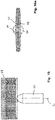
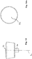
- FIG. 13 to 15 A more detailed view how the producing and loosing of said form fit can take place is depicted by Figs. 13 to 15 .
- the following design is advantageous:
- the applicator 15 can be stuck onto the coupling potion 14 of the valve body 13 by means of a straight movement along the longitudinal axis L, see the straight arrow.
- the applicator 15 is turned for substantially 90° (in clockwise direction here), as visualized by Fig. 14 .
- the valve body 13 remains stationary, it does not move during this locking process.
- the shaft of applicator 15 is not completely cylindrical but locally flattened, at least between the feed-in opening of the applicator 15 and the area for interaction with the snap-on cap 22.
- Said area, designed for accomplishing a form fit (positive interlocking fit) interaction of the applicator 15 with the snap-on cap 22 is positioned above the valve body 13.
- the snap-on cap 22 is designed that way that it can securely be snapped onto a complementary portion of the syringe 4 or, more exactly, onto a complementary portion of the housing HS formed by the syringe, as shown by Figure 4 .
- the snap-on cap 22 may have hooks 45 that snap into recesses or windows 46 of said housing HS as soon as the snap-on cap 22 has reached its final position, see what is shown by Fig. 4 and Fig. 1 . Moreover, the snap-on cap 22 secures the valve body 13 against extraction out of the valve seat 12.
- the interconnection between the valve body 13 and the applicator 15 is fluid tight.
- said tightness can be provided by the annular extension 25 of the applicator 15. Said annular extension 25 is stuck over the cylindrical flange CF of the valve body 13.
- valve body 13 even forms an annular groove so that the annular extension 25 of the applicator 15 is caught with its outer jacket JA as well as with its inner jacket. If a proper dimensioning and layout is provided, the interconnection can be designed that way that the annular extension 25 undergoes an elastic compression when being stuck over the cylindrical flange 26.
- the detaching of the applicator 15 shown is possible with the bare hands of the user, without using any tool, regardless whether a snap-on cap 22 is used or not.
- the interconnection that is formed between the valve body 13 of the applicator 15 allows itself the transfer of torque. That way the valve body 13 can be rotated by rotating the applicator 15.
- An optimized technical design provides that such a torque proof interconnection is realized by means of at least one protrusion or at least one tooth extending from the valve body 13 and gripping into a complementary recess of the applicator 15, or vice versa. Such a construction provides for positive locking fit in the direction of rotation.
- valve body 13 is equipped with two fully internal ducts 16 and 17.
- said ducts 16, 17 extend from the jacket portion of the valve body 13 into the interior of the valve body 13.
- the said jacket portion of the valve body 13 has preferably a conical shape. That way it is easier to grant tightness without burdensome narrowing of the tolerances, and to perform a very compact change of direction of the duct formed that way.
- said ducts 16 and 17 preferably meet a central output duct 18.
- This central output channel 18 is embodied along the rotational axis L of the valve body 13. In most cases said ducts 16 and 17 extend orthogonally to the rotational axis L of the valve body 13.
- the central output channel 18 is in fluidal connection with the duct 19 embodied in the applicator 15, more particular, embodied fully in the interior of the applicator 15.
- each pressure onto the plunger 3 expels the substances to be applied out of the reservoirs 5, 6.
- the substances flow through their ducts 20 and 21 in the syringe and enter through according mouth openings into the ducts 16 and 17 of the valve body 13. After having passed the ducts 16 and 17 of the valve body 13, the substances are fed into the central output channel 18 of the valve body 13. Nevertheless it is preferred that the two substances do not yet meet or mix here, for that purpose the central output chancel 18 provides two parallel but fully separated ducts.
- the substances flow into the duct 19 embodied in the applicator 15.
- the two substances are still kept apart for some distance within the duct 19. That way they will meet for first time when they arrive directly at the static mixer embodied within the applicator 15.
- the substances to be applied leave the internal area of the applicator system through the at least one mouth 27 of the applicator 15.
- the central output channel 18 has, as already described, in most cases two different tracks or ducts, too, that do not stand in any fluidal communication with one another. The reason for this is that it is in most cases not allowed that the different substances to be applied mix with one another before they have reached the applicator. Each mixing with one another would start a chemical reaction that has to be started completely out of the reusable parts of the applicator system in order to avoid clogging or detrimental effects in regard to the rest of the stored substances.
- a very interesting optional point is that even the duct 19 within the applicator 15 is designed that way that it forms in its beginning for some millimeters an entrance with two completely different and separated tracks that keep the at least two substances to be applied separated within the applicator until they enter into the static mixer within the applicator.
- the valve body 13 is rotatably hold by the valve seat 12, so that the valve body 13 can be rotated around the axis L by means of rotating the applicator 15. As soon as the valve body 13 is turned for example 90°, the situation is as shown by Figure 2 . That means the internal ducts 16 and 17 of the valve body 13 are not any longer in fluidal communication with the ducts 20 and 21 in the syringe 4 or - more generally spoken - in the body forming the reservoir. Instead, the valve body 13 blocks or seals the ducts 20 and 21, so that it is not possible to expel substances from the reservoir or reservoirs 5, 6.
- valve and/or the valve seat realize at least one rotation stopper where the rotation of the valve body 13 comes to an end as soon as the valve body is in its position where the ducts fully opened
- the duct 19 embodied in the applicator 15 is equipped with a static mixer 24 that mixes the substances expelled into the interior of the applicator during their flow along the interior of the applicator.
- the static mixer normally consists of a number of stationary hurdles that deflect the stream of the different substances repeatedly, back and forth, so that the local direction of flow changes. That leads to a mixing of the jointly flowing substances.
- the static mixer as such can be of one of the types as disclosed by prior published, granted patents EP 0730913 or EP 0885651 .
- the designs of the mixers as such and their physical embodiment and their fixation within or integration into an outer guiding tube is included into this application be reference.
- Fig. 4 Another optional detail is shown by Fig. 4 .
- the duct 19 embodied in the applicator 15 branches after completion of the mixing so that the mixed substances are locally dispensed trough several mouths 27 of the applicator at a number of places between the bristles or teeth of the applicator. That way a more uniform loading of the applicator with the substances to be applied is made sure.
- the second embodiment is very similar to the first embodiment so that all things described above for the first embodiment apply to the second embodiment, too, as long as nothing different is notified in the following.
- the body which serves as a reservoir.
- the body is constructed as a pump whose piston is driven by means of a screw driving mechanism.
- the main body portion 29 forms two reservoirs 5 and 6, too.
- the main body portion 29 holds a threaded spindle 30 within each reservoir 5 and 6.
- Each threaded spindle 30 carries a piston 31 that rides with its female thread on the male thread of said spindle 30.
- At the distal end each spindle 30 carries a sprocket 32.
- the main body portion 29 bears at its distal end a tubular sleeve 34 with an internal toothing 35.
- This tubular sleeve 34 is rotatably hold by the main body portion 29.
- the tubular sleeve 34 preferably possesses a tubular extension 36 that is stuck into the central guiding tube 37 of the main body portion 29.
- the internal toothing 35 and the sprockets 32 engage. That way the sprockets 32 are rotated as soon as the user turns the tubular sleeve 34. As soon as the sprockets 32 rotate, the threaded spindle 30 screws the pistons 31 in direction to the proximal i. e. in direction toward the applicator, for example. That way the substance to be applied is expelled out of its reservoir 5 or 6.
- valve mechanism and the way how to fix the applicator, for example to the valve body 13, are fully the same as described above for the first embodiment.
- the third embodiment is very similar to the first and the second embodiment, too. For that reason, all things described above apply to the third embodiment, too, as long as nothing different is notified in the following.
- the main body portion 29 forms a kind of bottle, in the case here a twin bottle with two different reservoirs 5 and 6.
- Each of the bottles preferably carries a bottleneck that is not shown in detail here.
- a sucking tube 38 is sunk into each reservoir 5 and 6.
- a said soap pump 39 is fixed.
- the soap pumps 39 may have a threaded cap each with which each soap pump is screwed onto the bottleneck assigned to it.
- the yoke 40 embodies a valve seat 12 as it is known from the first and the second embodiment. In the same manner as in the first and the second embodiment, the valve seat 12 accommodates a valve body 13.
- the valve body 13 is designed as already described. In Figure 11 it is displayed in its open position. In this position of the valve body 13 there is a continuous, uninterrupted duct between each of the soap pumps and the internal duct 19 of the applicator 15 that ends into at least one mouth 27 of the applicator.
- valve body 13 it is possible to couple at least one and preferably different applicators to the valve body 13 in a manner that allows to turn the valve body 13 by turning the applicator. That way the valve body 13 can be brought into its closed position, as described before.
- the applicator 15 is preferably equipped with a static mixer 24 that thoroughly mixes the substances to be applied that are fed by means of their ducts into the central output channel 18 in order to be conveyed from there to the internal duct 19 of the applicator.
- the invention is very advantageous if only one and the same applicator is used as a one-way applicator being disposed after application.
- Figure 16 discloses an internally fed applicator in the shape of a frontal comb 47.
- a frontal comb 47 Preferably all or at least a number of its tines 48 have an internal duct for dispensing the product to be applied through an orifice 49 at the end of the respective tine 48.
- the shaft 50 of this applicator accommodates a mixer which is of the type as explained before. Moreover the shaft 50 is embodied preferably in a way that it is fit for coupling to the snap-on cap, for example, as explained before. The features allowing this coupling action are not depicted here.
- the applicators are preferably designed such, that the 2 different substances to be mixed enter into the shaft 50 without being mixed before so that the substances come for first time in contact when they directly reach the mixer.
- the tines 48 being equipped with the internal ducts show a concave outer end with one or better opposite two lateral openings - so that their orifice 49 is not obstructed when the outer end of the tine comes in contact with the skin or the hairs.
- tines 48 that are not provided with internal ducts show an outer end having a chisel-like shape. Such a design improves the combing effect.
- Figure 17 discloses another alternative applicator. Compared to the applicator according to figure 16 this applicator may exhibit the only difference that no tines 48 are provided but bristles, in the shape of a bristle covering 51. The single bristles are flexible and in most of the cases none of the bristles is internally fed. Instead, even if an internal feeding is provided, such an internal feeding is accomplished by means of orifices that open out into the area of the roots of the bristles.
- shaft 50 of this applicator may accommodate the mixer of the type explained before if any mixer is used.
- shaft 50 is designed preferably in a way that it is fit for coupling to the snap-on cap 22, as explained before, for example. This is not depicted here.
- Figure 18 discloses another alternative applicator.
- This applicator may carrying no tines 48 or bristles but a blank, plane, convex or - at least slightly - concave surface 52.
- Said surface 52 may be flocked. It is a surface for spreading and smearing cosmetics.
- This applicator can be internally fed, too. In other cases such an applicator has no internal feeding. It is mounted to the device and used after prior outputting of cosmetics to the skin or hairs.
- Applicator system 1 for applying at least one flowable substance, with a body 2 forming at least one reservoir 5; 6 for storing at least one substance to be applied, a pump device for expelling the at least one substance out of the reservoir 5; 6, and a duct system 16, 17, 18, 19, 20, 21 for feeding the at least one pumped substance from the reservoir 5; 6 out of the body through the applicator 15 to at least one mouth 27 of the applicator 15, and a detachable applicator 15 for applying the at least one substance which is designed that way that the applicator system 1 comprises a movable valve 12, 13 that can be moved from an open to a closed position and vice versa by means of moving the applicator 15 relative to the body 2.
Landscapes
- Coating Apparatus (AREA)
Priority Applications (2)
| Application Number | Priority Date | Filing Date | Title |
|---|---|---|---|
| EP18213658.0A EP3669697A1 (de) | 2018-12-18 | 2018-12-18 | Versiegelbares, intern zugeführtes applikatorsystem |
| PCT/EP2019/086093 WO2020127583A1 (en) | 2018-12-18 | 2019-12-18 | Sealable internally fed applicator system |
Applications Claiming Priority (1)
| Application Number | Priority Date | Filing Date | Title |
|---|---|---|---|
| EP18213658.0A EP3669697A1 (de) | 2018-12-18 | 2018-12-18 | Versiegelbares, intern zugeführtes applikatorsystem |
Publications (1)
| Publication Number | Publication Date |
|---|---|
| EP3669697A1 true EP3669697A1 (de) | 2020-06-24 |
Family
ID=64745954
Family Applications (1)
| Application Number | Title | Priority Date | Filing Date |
|---|---|---|---|
| EP18213658.0A Withdrawn EP3669697A1 (de) | 2018-12-18 | 2018-12-18 | Versiegelbares, intern zugeführtes applikatorsystem |
Country Status (2)
| Country | Link |
|---|---|
| EP (1) | EP3669697A1 (de) |
| WO (1) | WO2020127583A1 (de) |
Citations (7)
| Publication number | Priority date | Publication date | Assignee | Title |
|---|---|---|---|---|
| US2446398A (en) * | 1946-09-21 | 1948-08-03 | Charley S Wilson | Handy comb |
| EP0305823A1 (de) * | 1987-08-29 | 1989-03-08 | Henkel Kommanditgesellschaft auf Aktien | Vorrichtung zur Abgabe mehrkomponentiger haarkosmetischer Produkte, insbesondere Haarfärbemittel |
| EP0730913A1 (de) | 1995-03-07 | 1996-09-11 | Wilhelm A. Keller | Bayonett-Anschlussvorrichtung zum Befestigen eines Zubehörteils an einer Mehrkomponenten-Kartusche oder Spendervorrichtung |
| EP0885651A1 (de) | 1997-06-18 | 1998-12-23 | Wilhelm A. Keller | Mischer |
| EP1201318A1 (de) * | 2000-10-20 | 2002-05-02 | L'oreal | Abgabeeinheit für die gleichzeitige Abgabe von zwei Produkten |
| WO2003094657A1 (en) * | 2002-03-21 | 2003-11-20 | Sung Il Kang | Hairdyeing apparatus |
| DE202006011101U1 (de) * | 2006-07-18 | 2007-12-06 | Schwan-Stabilo Cosmetics Gmbh & Co. Kg | Spender |
-
2018
- 2018-12-18 EP EP18213658.0A patent/EP3669697A1/de not_active Withdrawn
-
2019
- 2019-12-18 WO PCT/EP2019/086093 patent/WO2020127583A1/en not_active Ceased
Patent Citations (8)
| Publication number | Priority date | Publication date | Assignee | Title |
|---|---|---|---|---|
| US2446398A (en) * | 1946-09-21 | 1948-08-03 | Charley S Wilson | Handy comb |
| EP0305823A1 (de) * | 1987-08-29 | 1989-03-08 | Henkel Kommanditgesellschaft auf Aktien | Vorrichtung zur Abgabe mehrkomponentiger haarkosmetischer Produkte, insbesondere Haarfärbemittel |
| EP0730913A1 (de) | 1995-03-07 | 1996-09-11 | Wilhelm A. Keller | Bayonett-Anschlussvorrichtung zum Befestigen eines Zubehörteils an einer Mehrkomponenten-Kartusche oder Spendervorrichtung |
| EP0885651A1 (de) | 1997-06-18 | 1998-12-23 | Wilhelm A. Keller | Mischer |
| EP1201318A1 (de) * | 2000-10-20 | 2002-05-02 | L'oreal | Abgabeeinheit für die gleichzeitige Abgabe von zwei Produkten |
| EP1201318B1 (de) * | 2000-10-20 | 2008-03-05 | L'oreal | Abgabeeinheit für die gleichzeitige Abgabe von zwei Produkten |
| WO2003094657A1 (en) * | 2002-03-21 | 2003-11-20 | Sung Il Kang | Hairdyeing apparatus |
| DE202006011101U1 (de) * | 2006-07-18 | 2007-12-06 | Schwan-Stabilo Cosmetics Gmbh & Co. Kg | Spender |
Also Published As
| Publication number | Publication date |
|---|---|
| WO2020127583A1 (en) | 2020-06-25 |
Similar Documents
| Publication | Publication Date | Title |
|---|---|---|
| US5152305A (en) | Applicator device | |
| US8021064B2 (en) | Packaging and applicator device | |
| US5913314A (en) | Combination salon tool device | |
| US6302607B1 (en) | Fluid applicators | |
| US20100186762A1 (en) | Hair highlighting applicator | |
| AU2018336706B2 (en) | Cap and vial applicator system for applying two cosmetic products | |
| EP1032287B1 (de) | Flüssigkeitsapplikatoren | |
| WO2014022420A1 (en) | Pen dispensers with cartridges and interchangeable tip applicators | |
| CN103607926B (zh) | 用于将护发产品应用到发缕上的装置 | |
| US20250275619A1 (en) | Hair coloring variegation device and method of use | |
| US20140311509A1 (en) | Disposable hair lightening applicator comb | |
| US6244273B1 (en) | Water comb | |
| US20210227947A1 (en) | Liquid Hair Product Dispenser | |
| US20130048003A1 (en) | Hair highlighting applicator comb | |
| US6722804B2 (en) | Applique package and method of manufacture | |
| CN110996714B (zh) | 化妆制品或护理制品的分配和施涂装置 | |
| JP2001523526A (ja) | 流体送り出しシステム | |
| EP3669999B1 (de) | Versiegelbares, intern zugeführtes applikatorsystem | |
| WO2020127583A1 (en) | Sealable internally fed applicator system | |
| DE29717267U1 (de) | Verpackung mit zwei Abteilungen und Verschlüsse dafür | |
| CN108697220A (zh) | 头发染杂色装置和使用方法 | |
| EP0264824B1 (de) | Spender für pastenartiges Produkt | |
| US20090311034A1 (en) | Shearing assembly | |
| US9943153B2 (en) | Applicator and a dye kit comprising said applicator | |
| KR200467165Y1 (ko) | 각도 조절수단을 갖는 브러쉬형 디스펜서 |
Legal Events
| Date | Code | Title | Description |
|---|---|---|---|
| PUAI | Public reference made under article 153(3) epc to a published international application that has entered the european phase |
Free format text: ORIGINAL CODE: 0009012 |
|
| STAA | Information on the status of an ep patent application or granted ep patent |
Free format text: STATUS: THE APPLICATION HAS BEEN PUBLISHED |
|
| AK | Designated contracting states |
Kind code of ref document: A1 Designated state(s): AL AT BE BG CH CY CZ DE DK EE ES FI FR GB GR HR HU IE IS IT LI LT LU LV MC MK MT NL NO PL PT RO RS SE SI SK SM TR |
|
| AX | Request for extension of the european patent |
Extension state: BA ME |
|
| STAA | Information on the status of an ep patent application or granted ep patent |
Free format text: STATUS: REQUEST FOR EXAMINATION WAS MADE |
|
| 17P | Request for examination filed |
Effective date: 20201216 |
|
| RBV | Designated contracting states (corrected) |
Designated state(s): AL AT BE BG CH CY CZ DE DK EE ES FI FR GB GR HR HU IE IS IT LI LT LU LV MC MK MT NL NO PL PT RO RS SE SI SK SM TR |
|
| STAA | Information on the status of an ep patent application or granted ep patent |
Free format text: STATUS: EXAMINATION IS IN PROGRESS |
|
| 17Q | First examination report despatched |
Effective date: 20221123 |
|
| STAA | Information on the status of an ep patent application or granted ep patent |
Free format text: STATUS: THE APPLICATION IS DEEMED TO BE WITHDRAWN |
|
| 18D | Application deemed to be withdrawn |
Effective date: 20230404 |