EP3669729A1 - Mécanisme d'emballage et de montage pour moteur électrique dans des appareils de petite et moyenne taille - Google Patents
Mécanisme d'emballage et de montage pour moteur électrique dans des appareils de petite et moyenne taille Download PDFInfo
- Publication number
- EP3669729A1 EP3669729A1 EP18846362.4A EP18846362A EP3669729A1 EP 3669729 A1 EP3669729 A1 EP 3669729A1 EP 18846362 A EP18846362 A EP 18846362A EP 3669729 A1 EP3669729 A1 EP 3669729A1
- Authority
- EP
- European Patent Office
- Prior art keywords
- motor
- seal
- packing
- isolating cover
- mounting mechanism
- Prior art date
- Legal status (The legal status is an assumption and is not a legal conclusion. Google has not performed a legal analysis and makes no representation as to the accuracy of the status listed.)
- Pending
Links
- 230000007246 mechanism Effects 0.000 title claims abstract description 45
- 238000012856 packing Methods 0.000 title claims abstract description 38
- 230000013011 mating Effects 0.000 claims abstract description 65
- 238000007789 sealing Methods 0.000 claims description 132
- XLYOFNOQVPJJNP-UHFFFAOYSA-N water Substances O XLYOFNOQVPJJNP-UHFFFAOYSA-N 0.000 claims description 13
- 230000008859 change Effects 0.000 claims description 12
- 230000003044 adaptive effect Effects 0.000 claims description 9
- 230000002093 peripheral effect Effects 0.000 claims description 9
- 230000003068 static effect Effects 0.000 claims description 9
- 230000009467 reduction Effects 0.000 abstract description 21
- 238000010521 absorption reaction Methods 0.000 abstract description 9
- 238000010586 diagram Methods 0.000 description 24
- 230000000694 effects Effects 0.000 description 19
- 230000006872 improvement Effects 0.000 description 16
- 238000001816 cooling Methods 0.000 description 5
- 230000006870 function Effects 0.000 description 4
- 238000000034 method Methods 0.000 description 4
- 239000000428 dust Substances 0.000 description 3
- 238000003032 molecular docking Methods 0.000 description 3
- 230000007423 decrease Effects 0.000 description 2
- 239000007788 liquid Substances 0.000 description 2
- 238000005457 optimization Methods 0.000 description 2
- 230000008569 process Effects 0.000 description 2
- 230000002035 prolonged effect Effects 0.000 description 2
- 230000009471 action Effects 0.000 description 1
- 239000000853 adhesive Substances 0.000 description 1
- 230000001070 adhesive effect Effects 0.000 description 1
- 230000004075 alteration Effects 0.000 description 1
- 230000009286 beneficial effect Effects 0.000 description 1
- 230000015572 biosynthetic process Effects 0.000 description 1
- 230000006835 compression Effects 0.000 description 1
- 238000007906 compression Methods 0.000 description 1
- 230000002596 correlated effect Effects 0.000 description 1
- 230000000875 corresponding effect Effects 0.000 description 1
- 238000002788 crimping Methods 0.000 description 1
- 230000005674 electromagnetic induction Effects 0.000 description 1
- 238000001914 filtration Methods 0.000 description 1
- 239000012530 fluid Substances 0.000 description 1
- 230000005484 gravity Effects 0.000 description 1
- 230000001788 irregular Effects 0.000 description 1
- 238000002955 isolation Methods 0.000 description 1
- 230000007774 longterm Effects 0.000 description 1
- 238000004519 manufacturing process Methods 0.000 description 1
- 239000000463 material Substances 0.000 description 1
- 230000000149 penetrating effect Effects 0.000 description 1
- 238000003825 pressing Methods 0.000 description 1
- 230000004044 response Effects 0.000 description 1
- 230000009466 transformation Effects 0.000 description 1
- 238000000844 transformation Methods 0.000 description 1
- 238000011144 upstream manufacturing Methods 0.000 description 1
- 238000004078 waterproofing Methods 0.000 description 1
Images


Classifications
-
- H—ELECTRICITY
- H02—GENERATION; CONVERSION OR DISTRIBUTION OF ELECTRIC POWER
- H02K—DYNAMO-ELECTRIC MACHINES
- H02K5/00—Casings; Enclosures; Supports
- H02K5/24—Casings; Enclosures; Supports specially adapted for suppression or reduction of noise or vibrations
-
- A—HUMAN NECESSITIES
- A47—FURNITURE; DOMESTIC ARTICLES OR APPLIANCES; COFFEE MILLS; SPICE MILLS; SUCTION CLEANERS IN GENERAL
- A47L—DOMESTIC WASHING OR CLEANING; SUCTION CLEANERS IN GENERAL
- A47L7/00—Suction cleaners adapted for additional purposes; Tables with suction openings for cleaning purposes; Containers for cleaning articles by suction; Suction cleaners adapted to cleaning of brushes; Suction cleaners adapted to taking-up liquids
- A47L7/0004—Suction cleaners adapted to take up liquids, e.g. wet or dry vacuum cleaners
-
- A—HUMAN NECESSITIES
- A47—FURNITURE; DOMESTIC ARTICLES OR APPLIANCES; COFFEE MILLS; SPICE MILLS; SUCTION CLEANERS IN GENERAL
- A47L—DOMESTIC WASHING OR CLEANING; SUCTION CLEANERS IN GENERAL
- A47L5/00—Structural features of suction cleaners
- A47L5/12—Structural features of suction cleaners with power-driven air-pumps or air-compressors, e.g. driven by motor vehicle engine vacuum
- A47L5/22—Structural features of suction cleaners with power-driven air-pumps or air-compressors, e.g. driven by motor vehicle engine vacuum with rotary fans
- A47L5/36—Suction cleaners with hose between nozzle and casing; Suction cleaners for fixing on staircases; Suction cleaners for carrying on the back
- A47L5/365—Suction cleaners with hose between nozzle and casing; Suction cleaners for fixing on staircases; Suction cleaners for carrying on the back of the vertical type, e.g. tank or bucket type
-
- A—HUMAN NECESSITIES
- A47—FURNITURE; DOMESTIC ARTICLES OR APPLIANCES; COFFEE MILLS; SPICE MILLS; SUCTION CLEANERS IN GENERAL
- A47L—DOMESTIC WASHING OR CLEANING; SUCTION CLEANERS IN GENERAL
- A47L9/00—Details or accessories of suction cleaners, e.g. mechanical means for controlling the suction or for effecting pulsating action; Storing devices specially adapted to suction cleaners or parts thereof; Carrying-vehicles specially adapted for suction cleaners
- A47L9/0081—Means for exhaust-air diffusion; Means for sound or vibration damping
-
- A—HUMAN NECESSITIES
- A47—FURNITURE; DOMESTIC ARTICLES OR APPLIANCES; COFFEE MILLS; SPICE MILLS; SUCTION CLEANERS IN GENERAL
- A47L—DOMESTIC WASHING OR CLEANING; SUCTION CLEANERS IN GENERAL
- A47L9/00—Details or accessories of suction cleaners, e.g. mechanical means for controlling the suction or for effecting pulsating action; Storing devices specially adapted to suction cleaners or parts thereof; Carrying-vehicles specially adapted for suction cleaners
- A47L9/22—Mountings for motor fan assemblies
-
- A—HUMAN NECESSITIES
- A47—FURNITURE; DOMESTIC ARTICLES OR APPLIANCES; COFFEE MILLS; SPICE MILLS; SUCTION CLEANERS IN GENERAL
- A47L—DOMESTIC WASHING OR CLEANING; SUCTION CLEANERS IN GENERAL
- A47L9/00—Details or accessories of suction cleaners, e.g. mechanical means for controlling the suction or for effecting pulsating action; Storing devices specially adapted to suction cleaners or parts thereof; Carrying-vehicles specially adapted for suction cleaners
- A47L9/28—Installation of the electric equipment, e.g. adaptation or attachment to the suction cleaner; Controlling suction cleaners by electric means
- A47L9/2889—Safety or protection devices or systems, e.g. for prevention of motor over-heating or for protection of the user
-
- H—ELECTRICITY
- H02—GENERATION; CONVERSION OR DISTRIBUTION OF ELECTRIC POWER
- H02K—DYNAMO-ELECTRIC MACHINES
- H02K5/00—Casings; Enclosures; Supports
- H02K5/04—Casings or enclosures characterised by the shape, form or construction thereof
- H02K5/10—Casings or enclosures characterised by the shape, form or construction thereof with arrangements for protection from ingress, e.g. water or fingers
-
- H—ELECTRICITY
- H02—GENERATION; CONVERSION OR DISTRIBUTION OF ELECTRIC POWER
- H02K—DYNAMO-ELECTRIC MACHINES
- H02K7/00—Arrangements for handling mechanical energy structurally associated with dynamo-electric machines, e.g. structural association with mechanical driving motors or auxiliary dynamo-electric machines
- H02K7/14—Structural association with mechanical loads, e.g. with hand-held machine tools or fans
Definitions
- the present invention relates to a mounting mechanism for a motor in an appliance, in particular to a waterproof packing and mounting mechanism for a motor in a small or medium-sized appliance.
- An electric motor is commonly known as a motor, which refers to an electromagnetic device for converting or transmitting electrical energy according to the law of electromagnetic induction, and mainly functions to generate a driving torque as a power source of an appliance or various machines.
- the mounting of the motor in the appliance needs to consider two aspects: one is fixing of the motor, which needs to prevent the start-up following rotation of the series-excited motor, so that the motor is fixed during normal operation; and the other is sealing, which prevents liquid such as water from entering a motor chamber during the use of the appliance to cause damage to the motor.
- small and medium-sized appliances of water sucking types have higher requirements for water proofing of motors.
- motors in such appliances are generally sealed and fixed by soft seals on the upper and lower sides, which achieve axial crimping fixation on the motors, so the sealing effect on the motors depends on the axial pressing force.
- the axial pressure is often large, and the soft seals lose elasticity after being pressed and cannot absorb the vibration of the motor during operation, so the noise is large; in addition, the large axial pressure easily causes damage to the soft seals, resulting in bad effects such as seal failure.
- the sealing structures of motors in small and medium-sized appliances such as wet and dry vacuum cleaners are relatively simple, and are all simply sealed by axial pressure seals, so the waterproof performance is poor.
- the sealing effect depends entirely on the amount of axial pressure, and the sealing performance is inversely proportional to the noise absorption capability of the seals under pressure, that is, if the better the sealing performance is, the worse noise the reduction capability is.
- the present invention aims to provide a packing and mounting mechanism for a motor in a small or medium-sized appliance, and the packing and mounting mechanism has strong noise absorption and noise reduction capability.
- an embodiment of the present invention provides a packing and mounting mechanism for a motor in a small or medium-sized appliance, including a housing, a motor in the housing, and a motor seat supporting the motor, wherein at least one isolating cover is provided inside the housing, the motor is axially disposed between the housing and the motor seat, a motor chamber for receiving the motor is formed among the housing, the motor seat and the isolating cover, an axial mating clearance is formed between the isolating cover and the motor seat, a axially-mated first seal is provided in the axial mating clearance, the first seal has an elastic supporting portion, the cross section of the elastic supporting portion is of a door-shaped structure, and the elastic supporting portion has an opening facing the axial direction of the motor.
- the first seal has an inner side wall, an outer side wall opposite to the inner side wall and having a certain distance from the inner side wall, and a top wall for connecting the inner side wall and the outer side wall, and the inner side wall, the outer side wall, and the top wall constitute the door-shaped structure having an opening.
- the top wall has a radian away from the opening.
- the motor seat is provided with a mounting groove
- the first seal is disposed in the mounting groove
- the motor seat further includes an inner flange, an outer flange opposite to the inner flange and a bottom portion between the inner flange and the outer flange, the inner flange, the bottom portion and the outer flange constitute the mounting groove
- the opening of the door-shaped portion faces the bottom portion
- the inner side wall abuts against the inner flange
- the outer side wall abuts against the outer flange
- the top wall abuts against the isolating cover.
- a first isolating cover and a lower cover are provided inside the housing, the first isolating cover is disposed on the radial periphery of the motor, the lower cover is disposed on the lower part and radial periphery of the motor seat, the motor chamber is formed among the housing, the motor seat and the first isolating cover, an outer chamber isolated from the motor chamber is formed among the motor seat, the first isolating cover and the lower cover, and the axial mating clearance is between the first isolating cover and the motor seat.
- a radial mating clearance is also formed between the first isolating cover and the motor seat, the first seal includes a first sealing portion in the radial mating clearance and a second sealing portion in the axial mating clearance, and the elastic supporting portion is disposed on the second sealing portion.
- the second sealing portion is at least partially exposed from the motor chamber, and the first sealing portion is a sealing mechanism having adaptive deformation according to the change in air pressure of the outer chamber.
- the first sealing portion is a lip-shaped sealing portion.
- a sealing gasket is provided between the first isolating cover and the lower cover, the first isolating cover has a first isolating cover inner edge and a first isolating cover outer edge, the lower cover has a peripheral portion on the periphery of the motor seat and an end portion on the axial end face of the motor seat, the peripheral portion is provided with a receiving groove for receiving the sealing gasket, and the first isolating cover outer edge abuts against the sealing gasket.
- a second seal is provided between the motor seat and the lower cover, the second seal has a seal side wall and a bottom wall, the seal side wall is disposed on the periphery of the motor seat, the seal side wall is between the motor seat and the peripheral portion of the lower cover, and the bottom wall is between an end face of the motor seat and an end portion of the lower cover.
- the seal side wall is corrugated, the bottom wall has a bottom edge connected to the side wall and an inner edge connected to the bottom edge, the seal side wall has a connecting end connected to the bottom edge and a free end opposite to the connection end, and the inner edge is closer to the free end than the bottom edge in the vertical direction.
- the inner edge extends obliquely from the connection point with the bottom edge toward an end portion of a second isolating cover
- the end portion of the second isolating cover is provided with at least one abutting portion abutting against the inner edge
- the end portion of the second isolating cover is also provided with a protruding portion abutting against the bottom edge
- other portion of the end portion of the second isolating cover except the protruding portion has a certain distance from the bottom edge.
- a second seal is provided between the isolating cover and the motor seat, and the packing and mounting mechanism further includes a follow-up rotation preventing structure for preventing other parts of the motor except a rotor, the motor seat, and the second seal from rotating;
- the follow-up rotation preventing structure includes a first mating portion disposed on the isolating cover, a second mating portion disposed on the second seal, and a third mating portion disposed on the motor seat, wherein every two of the first mating portion, the second mating portion, and the third mating portion are mated with each other.
- the first mating portion is a positioning groove
- the second mating portion is a positioning protrusion with a straight positioning convex slot
- the third mating portion is a fixed protrusion extending toward the periphery of the motor seat, the fixed protrusion being mated with the positioning convex slot, the positioning protrusion being mated with the positioning groove.
- a third seal is provided between the housing and the motor, the third seal has a vertical edge and at least one lip edge disposed at an angle to the vertical edge, the lip edge and the vertical edge form a third lip opening, the vertical edge is disposed on the periphery of the motor and abuts against the periphery of the motor, the lip edge abuts against the housing, and the third lip opening faces the motor chamber.
- the motor seat has a mounting portion, the mounting portion has a first side and a second side opposite to the first side, the motor is disposed on the first side, a static impeller is disposed on the second side, the motor has an output shaft, a dynamic impeller is disposed on the output shaft, and the static impeller is on the periphery of the dynamic impeller.
- the small or medium-sized appliance is a wet and dry vacuum cleaner, a water aspirator, a water pump, or a humidifier.
- the present invention has the beneficial effects: the first seal has an elastic supporting portion, the cross section of the elastic supporting portion is of a door-shaped structure, and the elastic supporting portion has an opening facing the axial direction of the motor. In this way, the first seal plays a supporting role and has good elasticity.
- the first seal is elastically deformed by an axial force to achieve a sealing function, so that the packing and mounting mechanism has strong noise absorption and noise reduction capability.
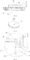
- FIG. 1 is an exploded structure diagram of a wet and dry vacuum cleaner having a packing and mounting mechanism, which includes a housing 30, a motor 32 in the housing 30, and a motor seat 34 supporting the motor 32. Specifically, the bottom of the motor 32 is fixedly connected to the motor seat 34.
- the packing and mounting mechanism is used to suspend, fix and effectively isolate the motor 32 in the housing 30, thereby preventing water or vapor from damaging the motor 32 and its accessories, and reducing the noise of the motor 32 during operation.
- At least one isolating cover is provided inside the housing 30, and the motor 32 is axially disposed between the housing 30 and the motor seat 34.
- the motor seat 34, the housing 30, and the isolating cover collectively form a motor chamber 36 for receiving the motor 32.
- a sealed end of the motor chamber 36 has a radial mating clearance 38, and a radially-mated first seal 40 is provided in the mating clearance 38.
- the sealed end refers to a joint between the motor seat and the isolating cover, so as to realize sealed docking.
- the first seal 40 is elastically deformed by a radial force to achieve a sealing function, and its sealing performance is independent of the axial pressure of the motor, so the first seal 40 does not lose its elasticity under large axial pressure, and has strong noise absorption and noise reduction capability.
- the first seal 40 includes at least one sealing portion, and the sealing portion is a sealing mechanism having adaptive deformation according to the change in air pressure difference between the inside and outside of the motor chamber. More specifically, the sealing portion is a lip-shaped sealing portion.
- the sealing portion includes a main lip, a sub lip, and a lip opening formed by the main lip and the sub lip. The lip opening faces the outside of the motor chamber.
- the isolating cover and the motor seat 34 also form an outer chamber isolated from the motor chamber 36, and the sealing portion is adaptively deformed with the change in air pressure of the outer chamber.
- a first isolating cover 42 and a second isolating cover 44 are provided inside the housing 30, the first isolating cover 42 is disposed on the radial periphery of the motor 32, and the second isolating cover 44 is disposed on the radial periphery of the motor seat 34.
- a motor chamber 36 for receiving the motor is formed among the housing 30, the motor seat 34 and the first isolating cover 42, the sealed end of the motor chamber 36 has a radial mating clearance 38, and a radially-mated first seal 40 is disposed in the mating clearance 38.
- the sealed end refers to the joint of the motor seat with the first isolating cover and the second isolating cover, so as to realize sealed docking.
- the first seal 40 is elastically deformed by a radial force for sealing, and its sealing performance is independent of the axial pressure of the motor, so the first seal 40 does not lose its elasticity under large axial pressure, and has strong noise absorption and noise reduction capability.
- a first outer chamber 45 is formed between the motor seat 34 and the second isolating cover 44, and a second outer chamber 47 is formed between the first isolating cover 42 and the second isolating cover 44.
- a first mating clearance 46 is formed between the motor seat 34 and the second isolating cover 44
- a second mating clearance 48 is formed between the first isolating cover 42 and the second isolating cover 44, and the first seal 40 is in the first mating clearance 46 and the second mating clearance 48.
- a J-shaped edge of the second isolating cover 44 facilitates the formation of the mating clearance.
- the J-shaped edge may also be adopted for the first isolating cover 42.
- the first seal 40 includes a first sealing portion 50 in the first mating clearance 46 and/or a second sealing portion 52 in the second mating clearance 48. Only one sealing portion is needed to achieve sealing. In the preferred embodiment, the first sealing portion and the second sealing portion are used at the same time to enhance the sealing effect.
- the motor chamber 36 is isolated from the first outer chamber 45 and the second outer chamber 47 by the first seal 40 to prevent water from entering the motor chamber along the matching clearances, thereby effectively protecting the motor and its accessories.
- first sealing portion 50 and the second sealing portion 52 are integrally provided, the first seal further includes a connecting portion 53 for connecting the first sealing portion 50 and the second sealing portion 52, and the connecting portion 53 is between the motor seat 34 and the first isolating cover 42.
- first sealing portion 50 and the second sealing portion 52 may also be provided separately, that is, provided as two independent parts.
- the first sealing portion 50 is a sealing mechanism having adaptive deformation according to the change of air pressure in the first outer chamber 45; and the second sealing portion 52 is a sealing mechanism having adaptive deformation according to the change of air pressure in the second outer chamber 47. That is, the sealing performance is adjusted through the change of external pressure. As the air pressure in the outer chambers increases, the sealing effects of the pressure adaptive sealing portions on the mating clearances increase, so the pressure required for the initial assembly is low. By adaptive adjustment based on the air pressure, a long-term high pressure state is avoided, the elastic attenuation of the first seal is retarded, and the service life of the first seal is prolonged. In addition, the second sealing portion 52 is at least partially exposed from the motor chamber.
- the first sealing portion 50 and the second sealing portion 52 are both lip-shaped sealing portions.
- the first sealing portion 50 includes a first main lip 54, a first sub lip 56, and a first lip opening 58 formed by the first main lip 54 and the first sub lip 56, the first lip opening 58 facing the first outer chamber 45; and the second sealing portion 52 includes a second main lip 60, a second sub lip 62, and a second lip opening 64 formed by the second main lip 60 and the second sub lip 62, the second lip opening 64 facing the second outer chamber 47.
- the lip openings are controlled by the changes of air pressure in the outer chambers. As the air pressure increases, the lip openings become large, the pressure on the connecting portion increases, and the sealing effect is enhanced.
- Wedge-shaped piston type pressure sealing portions may also be used to change the sealing performance with the changes of air pressure in the chambers.
- the first main lip 54 abuts against the second isolating cover 44, and the first sub lip 56 abuts against the motor seat 34; the second main lip 312 abuts against the second isolating cover 44, and the second sub lip 62 abuts against the first isolating cover 42.
- the main lips are thicker than the sub lips, the main lips are mainly used for abutment, the sub lips are mainly used for pressure deformation, the thin sub lips are deformed faster in response to the air pressure and adjusted more smoothly, and the deformed sub lips have large contact surface and strong action with the abutted portions and better sealing effect, thereby effectively preventing water from entering the motor chamber from the sub lips, and guaranteeing the sealing property of the motor chamber.
- the first seal 40 includes a third elastic portion 66
- the third elastic portion 66 is on the side of the first seal 40 facing away from the motor chamber 36, and the third elastic portion 66 abuts against a side wall of the first isolating cover 42 or the second isolating cover 44 to achieve strong elasticity.
- the third elastic portion 66 increases the assembly stability and noise absorption performance of the first seal 40.
- the third elastic portion 66 has a hollow column 68 for vibration reduction and noise reduction.
- the hollow column 68 increases the elasticity of the third elastic portion 66 and plays a role in reducing vibration and noise.
- a lower cover 70 for supporting the motor seat 34 is provided in the housing 30, and a bottom seal ring 72 for flexible sealing is provided between the lower cover 70 and the motor seat 34.
- the lower cover 70 and the second isolating cover 44 may be independent parts or an integrated part, and are made of the same or different materials.
- an impeller chamber cover 74 is provided at the bottom of the motor seat 34
- an impeller chamber 76 is formed between the impeller chamber cover 74 and the motor seat 34
- the bottom seal ring 72 is disposed between the bottom of the impeller chamber cover 74 and the lower cover 70.
- the bottom seal ring 72 separates the first outer chamber 45 from an air inlet chamber, which indirectly increases the sealing property of the motor chamber 36.
- the air inlet chamber is an air draft side filtering chamber of the vacuum cleaner.
- the motor of the vacuum cleaner drives an impeller to rotate to generate suction force.
- the fluid path is: a filter of the appliance ⁇ the air inlet chamber ⁇ the impeller chamber ⁇ the first outer chamber ⁇ the second outer chamber ⁇ an air outlet end.
- the bottom seal ring for flexible sealing is only subjected to axial pressure caused by the gravity of the motor, the motor seat, and the impeller, and the bottom seal ring 72 can maintain its own elasticity.
- the cross section of the bottom seal ring 72 is H-shaped or X-shaped.
- the seal ring with a regular cross section is easy to manufacture, so preferably, the bottom seal ring 72 is an inner and outer double-lip seal ring.
- the bottom seal ring 72 includes a first lip 78, a second lip 80, a third lip 82, and a fourth lip 84, where the first lip 78 and the second lip 80 form a first directional lip opening 86 facing the motor seat, the second lip 80 and the third lip 82 form a third directional lip opening 90 facing the first outer chamber 45, the third lip 63 and the fourth lip 84 form a second directional lip opening 88 facing the isolating cover, and the first lip 78 and the fourth lip 84 form a fourth directional lip opening 92 opposite to the third directional lip opening, that is, the fourth directional lip opening 92 faces the air inlet chamber.
- the third directional lip opening and/or the fourth directional lip opening are opened under the pressure to enhance the sealing effect.
- the bottom seal ring can absorb the vibration of the motor, thereby ensuring the noise reduction effect while achieving the sealing effect.
- the first directional lip opening and the second directional lip opening are opened under the pressure to enhance the sealing effect;
- the four lips of the bottom seal ring are elastically deformed, and at least two upper and lower lips fit with the motor seat or the isolating cover more closely to ensure the sealing effect.
- a groove 96 is provided on the top of the lower cover, and the groove can effectively limit the bottom seal ring 72 to prevent shifting.
- a protrusion 98 is provided on the periphery of the housing of the motor 32, the isolating cover includes an open end 100, the protrusion 98 is engaged with the open end along the axis of the motor 32, and a flexible gasket 102 is provided between the protrusion 98 and the open end 100.
- the flexible gasket 102 is used for fixing the motor and reducing vibration and noise. The position of the flexible gasket 102 is described in detail.
- the flexible gasket 102 is sandwiched above the protrusion 98 and below the open end to fix the motor axially. Above and below are for the directions of the appliance structure shown in FIG. 2 .
- the protrusion 98 is on the lower side of the flexible gasket 102, the motor housing is on the inner side, and the open end 100 is on the upper side and the outer side.
- the upper part of the flexible gasket 102 communicates with the external air
- the lower part of the flexible gasket 102 is the motor chamber 36
- the motor chamber also communicates with the external air.
- the vacuum cleaner is provided with a motor cooling air duct. When the motor is operating, cooling air enters the motor chamber from the upper part, and flows out of the motor chamber after cooling the motor. The flow direction of the cooling air is shown by arrows in FIG. 2 .
- the upstream and downstream of the motor cooling air duct can be air-tightly isolated, while the technical effects of vibration reduction and noise reduction are maintained.
- the flexible gasket 102 is a non-circular gasket.
- the flexible gasket 102 is a polygonal gasket, and may also be oval or in other irregular shapes. Any shape capable of preventing follow-up rotation of the motor is within the protection scope of this case.
- the flexible gasket 102 is a rectangular gasket.
- the protrusion 98 is provided with at least one lug in the radial direction of the motor.
- the lug cooperates with the open end and the flexible gasket to prevent follow-up rotation.
- the cross section of the flexible gasket 102 is circular, and may also be in other shapes, for example, X-shaped, H-shaped, etc., and the O-shaped cross section is easier to process.
- the cross section of the flexible gasket 102 is hollow O-shaped, and the hollow O-shaped cross section has better vibration reduction and noise reduction effects.
- the first seal 40, the bottom seal ring 72, and the flexible gasket 102 are assembled by means of cooperation of their shapes and corresponding shapes of respective components of the vacuum cleaner, and are fixedly connected to the vacuum cleaner without the use of screws, bolts, buckles, adhesives, etc.
- the assembly structure of the present invention realizes the isolation of the motor chamber through the first seal, the first seal achieves sealing by a radial force, and its sealing performance is independent of the axial pressure of the motor, so the first seal does not lose its elasticity under large axial pressure and has strong noise absorption and noise reduction capability;
- the first seal of the assembly structure of the present invention has a first sealing portion and a second sealing portion and is of a lip-shaped structure, and its sealing effect is positively correlated to the air pressure in each outer chamber and adaptively adjusted according to the air pressure, so the first seal is not in a high pressure state for a long time, the elastic attenuation of the first seal is retarded, and the service life of the first seal is prolonged;
- the first seal of the assembly structure of the present invention has a third elastic portion, and the hollow column of the third elastic portion further increases the noise reduction performance;
- the assembly structure of the present invention also has a flexible gasket, which achieves the effects of vibration reduction, noise reduction and sealing; and the assembly structure of
- the dry and wet vacuum cleaner is taken as an example above to describe the technical solution disclosed in this preferred embodiment in detail. It should be noted that the packing and mounting mechanism provided by this preferred embodiment is also applicable various small and medium-sized appliances such as a water aspirator, a water pump, or a humidifier in which a motor is mounted as a power source and which uses liquid such as water during use.
- the vacuum cleaner includes a dust cylinder 108 and rollers 109 below the dust cylinder 108.
- the packing and mounting mechanism also includes a housing 110, a motor 112 in the housing 110, and a motor seat 114 supporting the motor 112.
- At least one isolating cover is provided inside the housing 110, and the motor 112 is axially disposed between the housing 110 and the motor seat 114.
- the motor seat 114, the housing 110, and the isolating cover collectively form a motor chamber 116 for receiving the motor 112.
- a sealed end of the motor chamber 116 has a radial mating clearance, and a radially-mated first seal 120 is provided in the mating clearance.
- the packing and mounting mechanism further includes a filter 122, and the filter 122 may be a flat filter 122 or a ring filter 122 or other type of filter 122.
- the first seal 120 also includes at least one sealing portion, and the sealing portion is a sealing mechanism having adaptive deformation according to the change in air pressure difference between the inside and outside of the motor chamber 116.
- the sealing portion is also a lip-shaped sealing portion.
- the sealing portion includes a main lip, a sub lip, and a lip opening formed by the main lip and the sub lip.
- the isolating cover and the motor seat 114 also form an outer chamber isolated from the motor chamber 116, and the sealing portion is adaptively deformed with the change in air pressure of the outer chamber.
- a first isolating cover 124 and a lower cover 126 are provided inside the housing 110, the first isolating cover 124 is disposed on the radial periphery of the motor 112, and the lower cover 126 is disposed on the lower part and radial periphery of the motor seat 114.
- a motor chamber 116 for receiving the motor 112 is formed among the housing 110, the motor seat 114 and the first isolating cover 124, the sealed end of the motor chamber 116 has a radial mating clearance, and a radially-mated first seal 120 is disposed in the mating clearance.
- the sealed end refers to a joint between the motor seat 114 and the first isolating cover 124, so as to realize sealed docking.
- the first seal 120 is elastically deformed by a radial force for sealing, and its sealing performance is independent of the axial pressure of the motor 112, so the first seal 40 does not lose its elasticity under large axial pressure, and has strong noise absorption and noise reduction capability.
- An outer chamber is formed among the motor seat 114, the first isolating cover 124, and the lower cover 126, and the sealing portion is adaptively deformed with the change in air pressure of the outer chamber. Further, a radial mating clearance is formed between the motor seat 114 and the first isolating cover 124, and the first seal 120 includes a first sealing portion 130 in the radial mating clearance.
- the motor chamber 116 is isolated from the outer chamber by the first sealing portion 130 to prevent water from entering the motor chamber 116 along the matching clearance, thereby effectively protecting the motor 112 and its accessories.
- an axial mating clearance is also formed between the motor seat 114 and the first isolating cover 124, and the first seal 120 is also in the axial mating clearance.
- the first seal 120 further includes a second sealing portion 134 in the axial mating clearance.
- the first sealing portion 130 and the second sealing portion 134 are integrally provided, and both the first sealing portion and the second sealing portion are at least partially exposed from the motor chamber.
- the second sealing portion 134 is at least partially exposed from the outer chamber formed by the motor seat 114, the first isolating cover 124, and the lower cover 126. Therefore, the first seal 120 can be adaptively deformed with the change in air pressure of the outer chamber.
- the first sealing portion 130 and the second sealing portion 134 may also be provided separately. Specifically, the first sealing portion 130 plays a main sealing role, the second sealing portion 134 plays a supporting role, and the second sealing portion 134 also plays a certain sealing role.
- the first sealing portion 130 includes a main lip 136 and a sub lip, a lip opening is formed between the main lip 136 and the sub lip, and the lip opening faces the second sealing portion 134. Further, the lip opening faces the outer chamber, and the open direction of the lip opening faces away from the motor chamber. Specifically, the first sealing portion 130 includes a first sub lip 138 and a second sub lip 140, the main lip 136 and the first sub lip 138 form a first lip opening 142, the main lip 136 and the second sub lip 140 form a second lip opening 144, and both the first lip opening 142 and the second lip opening 144 face the second sealing portion 134.
- main lip 136 extends longitudinally along the axis of the motor 112, the main lip 136 abuts against the periphery of the motor seat 114, and the sub lips abut against the first isolating cover 124.
- the main lip 136 is spaced a certain distance from the first isolating cover 124.
- the first sealing portion 130 further includes a raised portion 146 extending from the main lip 136, the raised portion 146 and the sub lips are on the same side of the main lip 136, and the raised portion 146 abuts against the first isolating cover 124.
- the raised portion 146 and the second sealing portion 134 are on two sides of the sub lips.
- the motor seat 114 has an inner flange 148, and the first sealing portion 130 has an inversion portion 150 connected to the main lip 136 and having a certain distance from the main lip 136.
- the inversion portion 150 is snapped on the inner flange 148 of the motor seat 114 to fix the motor seat 114 and the first seal 120, enhance the fit between the main lip 136 and the inner flange 148, and further improve the sealing effect on the motor chamber 116.
- the motor seat 114 is provided with a mounting groove 152, and the first seal 120 is disposed in the mounting groove 152. Specifically, the second sealing portion 134 is disposed in the mounting groove 152.
- the first seal 120 has an elastic supporting portion 154.
- the cross section of the elastic supporting portion 154 is substantially of a door-shaped structure, and the elastic supporting portion 154 has an opening facing the axial direction of the motor 112.
- the cross section of the elastic supporting portion may also be circular, polygonal or in other shape, and more preferably, the cross section is of a hollow structure, as long as the elastic supporting portion can play a supporting role and have elasticity.
- the elastic supporting portion 154 is disposed on the second sealing portion 134, and the opening of the elastic supporting portion 154 faces downward.
- the motor seat 114 further includes an outer flange 156 opposite to the inner flange 148 and a bottom portion 158 between the inner flange 148 and the outer flange 156.
- the inner flange 148, the bottom portion 158, and the outer flange 156 constitute a mounting groove 152, and the opening of the door-shaped portion 154 faces the bottom portion 158.
- the second sealing portion 134 has an inner side wall 160, an outer side wall 162 opposite to the inner side wall 160 and having a certain distance from the inner side wall 160, and a top wall 164 for connecting the inner side wall 160 and the outer side wall 162.
- the inner side wall 160, the outer side wall 162, and the top wall 164 constitute the door-shaped portion 154 having an opening.
- the inner side wall 160 has the same thickness as the main lip 136 of the first sealing portion 130, and the both extend along the axis of the motor 112.
- the inner side wall 160 abuts against the inner flange 148 of the motor seat 114
- the outer side wall 162 abuts against the outer flange 156 of the motor seat 114
- the top wall 164 has a radian away from the opening and abuts against the isolating cover, and specifically, the top wall 164 abuts against the first isolating cover 124.
- a sealing gasket 166 is provided between the first isolating cover 124 and the lower cover 126, the first isolating cover 124 has a first isolating cover inner edge 168 and a first isolating cover outer edge 170, the lower cover 126 has a peripheral portion 172 on the periphery of the motor seat 114 and an end portion 174 on the axial end face of the motor seat 114, the peripheral portion 172 is provided with a receiving groove for receiving the sealing gasket 166, and the first isolating cover outer edge 170 is in the receiving groove and abuts against the sealing gasket 166. Further, the cross section of the sealing gasket 166 is O-shaped.
- the cross section of the sealing gasket 166 may also be in other shape, such as X-shaped, H-shaped, etc.
- the O-shaped cross section is easier to process.
- the cross section of the sealing gasket 166 is hollow O-shaped, and the hollow O-shaped cross section has better vibration reduction and noise reduction effects.
- the first sealing portion 130 is between the motor seat 114 and the first isolating cover inner edge 168. Specifically, the first sealing portion 130 is between the inner flange 148 of the motor seat 114 and the first isolating cover inner edge 168. The main lip 136 abuts against the inner flange 148 of the motor seat 114, and the sub lips abut against the first isolating cover inner edge 168.
- a second seal 178 is provided between the motor seat 114 and the lower cover 126, the second seal 178 has a seal side wall 180 and a bottom wall 182, the seal side wall 180 is disposed on the periphery of the motor seat 114, the seal side wall 180 is between the motor seat 114 and the peripheral portion 172 of the lower cover 126, and the bottom wall 182 is between the end face of the motor seat 114 and the end portion 174 of the lower cover 126.
- the seal side wall 180 is corrugated.
- the bottom wall 182 has a bottom edge 184 connected to the side wall and an inner edge 186 connected to the bottom edge 184.
- the seal side wall 180 has a connecting end connected to the bottom edge 184 and a free end opposite to the connection end.
- the inner edge 186 is closer to the free end than the bottom edge 184, that is, the inner edge 186 is recessed inward for a certain distance. In this way, a margin is provided for the squeezing between the motor seat 114 and the lower cover 126 to prevent the second seal 178 from being crushed.
- the bottom wall 182 of the second seal 178 may also be of other vibration reduction structure, such as a hollow structure or a corrugated structure.
- the inner edge 186 extends obliquely from the connection point with the bottom edge 184 toward the end portion 174 of the lower cover 126.
- the end portion 174 of the lower cover 126 is provided with at least one abutting portion 188 abutting against the inner edge 186.
- two abutting portions 188 are provided at interval.
- the end portion 174 of the lower cover 126 is also provided with a protruding portion 190 abutting against the bottom edge 184, the protruding portion 190 of a second isolating portion abuts against the bottom edge 184, and other portion of the end portion 174 except the protruding portion 190 has a certain distance from the bottom edge 184, so that a certain margin can be provided for the squeezing between the motor seat 114 and the lower cover 126 to further prevent the second seal 178 from being crushed.
- the packing and mounting mechanism for the motor 112 in the small or medium-sized appliance further includes a follow-up rotation preventing structure, thereby preventing other parts of the motor 112 except a rotor, the motor seat 114, and the second seal 178 from rotating, that is, the motor 112, the motor seat 114, and the second seal 178 do not follow the rotor of the motor 112 to rotate, and the relative positions of the motor 112, the motor seat 114, and the second seal 178 in the circumferential direction remain unchanged.
- the follow-up rotation preventing structure includes a first mating portion 192 disposed on the lower cover 126, a second mating portion 194 disposed on the second seal 178, and a third mating portion 196 disposed on the motor seat 114. Every two of the mating portion 192, the second mating portion 194, and the third mating portion 196 are mated with each other, thereby limiting mutual circumferential rotation among the motor 112, the motor seat 114, and the second seal 178.
- the first mating portion 192 is a positioning groove
- the second mating portion 194 is a positioning protrusion with a straight positioning convex slot
- the third mating portion 196 is a fixed protrusion extending toward the periphery of the motor seat 114, the fixed protrusion being mated with the positioning convex slot, the positioning protrusion being mated with the positioning groove.
- the first mating portion 192 may also be provided as a positioning groove
- the second mating portion 194 is provided as a straight slot
- the third mating portion 196 is provided as a fixed protrusion, the fixed protrusion penetrating the straight slot and being mated with the straight slot and the positioning groove.
- the motor is disposed on a first side of the motor seat 114, and a dynamic impeller is disposed on a second side of the motor seat opposite to the first side.
- the motor seat 114 has a mounting portion 198, the motor 112 is disposed on a first side of the mounting portion 198, a static impeller 200 is disposed on a second side of the mounting portion 198 opposite to the first side, the mounting portion 198 is provided with a plurality of screw holes 202 for fixing the motor 112, and the inner flange 148 of the motor seat 114 is disposed on the mounting portion 198 and located on the periphery of the motor 112.
- the motor 112 has an output shaft, a dynamic impeller 204 is disposed on the output shaft, and the static impeller 200 is on the periphery of the dynamic impeller 204.
- the motor seat 114 may be used as an open diffuser to diffuse the wind generated by the dynamic impeller 204 to the air duct.
- the static impeller 200 surrounds a receiving cavity 203, and the dynamic impeller 204 is in the receiving cavity 203. Since the static impeller 200 is on the periphery of the dynamic impeller 204, the dynamic impeller 204 is prevented from being thrown out.
- the dynamic impeller 204 is provided with a fixing hole 206, and the dynamic impeller 204 is detachably disposed on the output shaft of the motor 112 through the fixing hole 206.
- the assembling method of the dynamic impeller 204 and the motor 112 is: the motor 112 is first fixed to the mounting portion 198 of the motor seat 114 by screws, then the dynamic impeller 204 is placed in the receiving cavity 203 surrounded by the static impeller 200, and the dynamic impeller 204 is mounted on the output shaft of the motor 112.
- a third seal 208 is provided between the housing 110 and the motor 112, the third seal 208 has a vertical edge 210 and at least one lip edge 212 disposed at an angle to the vertical edge 210, the lip edge 212 and the vertical edge 210 form a third lip opening 214, the vertical edge 210 is disposed on the periphery of the motor 112 and abuts against the periphery of the motor 112, the lip edge 212 abuts against the housing 110, and the third lip opening 214 faces the motor chamber 116.
- the third seal 208 also has a transverse edge 216 disposed at an angle to the vertical edge 210, the transverse edge 216 and the lip edge 212 are on two sides of the vertical edge 210 respectively, and the transverse edge 216 abuts against an end of the motor 112.
Landscapes
- Engineering & Computer Science (AREA)
- Power Engineering (AREA)
- Mechanical Engineering (AREA)
- Motor Or Generator Frames (AREA)
- Gasket Seals (AREA)
Applications Claiming Priority (5)
| Application Number | Priority Date | Filing Date | Title |
|---|---|---|---|
| CN201610837898 | 2016-09-21 | ||
| CN201710696602.9A CN107863835B (zh) | 2016-09-21 | 2017-08-15 | 中小型电器中电机的封隔安装机构 |
| CN201710696963.3A CN107863836B (zh) | 2016-09-21 | 2017-08-15 | 中小型电器中电机的封隔安装机构 |
| CN201710696343.XA CN107863834B (zh) | 2016-09-21 | 2017-08-15 | 中小型电器中电机的封隔安装机构 |
| PCT/CN2018/100643 WO2019034079A1 (fr) | 2016-09-21 | 2018-08-15 | Mécanisme d'emballage et de montage pour moteur électrique dans des appareils de petite et moyenne taille |
Publications (2)
| Publication Number | Publication Date |
|---|---|
| EP3669729A1 true EP3669729A1 (fr) | 2020-06-24 |
| EP3669729A4 EP3669729A4 (fr) | 2021-04-28 |
Family
ID=61699198
Family Applications (1)
| Application Number | Title | Priority Date | Filing Date |
|---|---|---|---|
| EP18846362.4A Pending EP3669729A4 (fr) | 2016-09-21 | 2018-08-15 | Mécanisme d'emballage et de montage pour moteur électrique dans des appareils de petite et moyenne taille |
Country Status (4)
| Country | Link |
|---|---|
| US (1) | US11552527B2 (fr) |
| EP (1) | EP3669729A4 (fr) |
| CN (3) | CN107863834B (fr) |
| WO (1) | WO2019034079A1 (fr) |
Families Citing this family (7)
| Publication number | Priority date | Publication date | Assignee | Title |
|---|---|---|---|---|
| CN107863834B (zh) * | 2016-09-21 | 2020-08-21 | 天佑电器(苏州)有限公司 | 中小型电器中电机的封隔安装机构 |
| CN108418334B (zh) * | 2018-05-02 | 2024-04-30 | 隆鑫通用动力股份有限公司 | 发电机密封壳体及发电机 |
| FR3086156B1 (fr) * | 2018-09-24 | 2020-08-28 | Seb Sa | Dispositif d’aspiration pour aspirateur domestique |
| CN109645898A (zh) * | 2019-01-15 | 2019-04-19 | 尚科宁家(中国)科技有限公司 | 一种扫地机器人 |
| CN110811424B (zh) * | 2019-12-03 | 2025-06-27 | 珠海格力电器股份有限公司 | 过滤件装配结构及吸尘器 |
| TWI747350B (zh) * | 2020-07-01 | 2021-11-21 | 威剛科技股份有限公司 | 馬達 |
| CN117691798B (zh) * | 2024-02-01 | 2024-04-05 | 爱几度(深圳)科技有限公司 | 一种静音电动马达 |
Family Cites Families (26)
| Publication number | Priority date | Publication date | Assignee | Title |
|---|---|---|---|---|
| US2000386A (en) * | 1935-05-07 | Electric fan | ||
| US2510130A (en) * | 1947-10-06 | 1950-06-06 | Byron Jackson Co | Liquid seal for submersible motors |
| US3491695A (en) * | 1968-02-27 | 1970-01-27 | Albert Blum | Submersible electric pump |
| USRE26783E (en) * | 1968-12-16 | 1970-02-03 | Submersible motor seal section | |
| US4377763A (en) * | 1981-03-19 | 1983-03-22 | Western Technology, Inc. | Seal section for a downhole pumping unit |
| US4797072A (en) * | 1987-06-19 | 1989-01-10 | Shop-Vac Corporation | Portable electric blower |
| US6593674B2 (en) * | 2001-02-26 | 2003-07-15 | Woodward Governor Company | Vibration isolator and actuator incorporating same for isolating integral electronics |
| JP2002364589A (ja) | 2001-06-05 | 2002-12-18 | Toshiba Tec Corp | 電動送風機及びこれを備える電気掃除機 |
| CN101242121B (zh) * | 2007-02-08 | 2011-09-14 | 台达电子工业股份有限公司 | 电机及其轴承支承结构 |
| GB2469049B (en) * | 2009-03-31 | 2013-04-17 | Dyson Technology Ltd | A cleaning appliance with steering mechanism |
| KR20100112928A (ko) * | 2009-04-10 | 2010-10-20 | 삼성광주전자 주식회사 | 팬 모터 케이스 실링부재 및 팬 모터 케이스 |
| DE102010029982A1 (de) * | 2010-06-11 | 2011-12-15 | Robert Bosch Gmbh | Fluiddichtender Elektromotor-Anschlussstecker, sowie Motor und konfektioniertes elektrisches Kabel |
| CN202309322U (zh) * | 2011-10-26 | 2012-07-04 | 北京万源工业有限公司 | 一种风力发电机组发电机密封结构 |
| CN202737711U (zh) * | 2012-08-27 | 2013-02-13 | 苏州首信电机有限公司 | 直流电机的风机传动结构 |
| CN103346632A (zh) * | 2013-07-23 | 2013-10-09 | 江阴市新润电器有限公司 | 一种轮毂发电机 |
| US20150132158A1 (en) * | 2013-11-08 | 2015-05-14 | Ge Oil & Gas Esp, Inc. | Electric submersible motor oil expansion compensator |
| CN203607998U (zh) * | 2013-11-25 | 2014-05-21 | 湖北惠洋电器制造有限公司 | 一种塑封电机结构 |
| CN203722382U (zh) * | 2014-01-23 | 2014-07-16 | 珠海格力电器股份有限公司 | 一种空调器及其风机组件轴承盖防水密封结构 |
| CN104810957B (zh) * | 2014-01-23 | 2018-09-07 | 珠海格力电器股份有限公司 | 一种空调器及其风机组件轴承盖防水密封结构 |
| CN104997463B (zh) * | 2014-04-23 | 2017-07-28 | 江苏美的清洁电器股份有限公司 | 用于吸尘器的进气装置和吸尘器 |
| CN203967878U (zh) * | 2014-06-06 | 2014-11-26 | 临海市誉达机电有限公司 | 一种防尘电机 |
| CN104879318A (zh) * | 2015-05-14 | 2015-09-02 | 苏州永捷电机有限公司 | 吸尘器电机 |
| FR3047124B1 (fr) * | 2016-01-26 | 2019-05-10 | Valeo Systemes Thermiques | Ensemble de support d'un moteur electrique, notamment dans un dispositif de chauffage, ventilation et/ou climatisation pour vehicule automobile |
| JP2017139929A (ja) * | 2016-02-05 | 2017-08-10 | 株式会社デンソー | モータ、および、これを用いた電動パワーステアリング装置 |
| CN107863834B (zh) | 2016-09-21 | 2020-08-21 | 天佑电器(苏州)有限公司 | 中小型电器中电机的封隔安装机构 |
| DE102019205781B4 (de) * | 2019-04-23 | 2025-06-12 | Audi Ag | Antriebsvorrichtung umfassend einen Elektromotor und einen Wechselrichter und Kraftfahrzeug |
-
2017
- 2017-08-15 CN CN201710696343.XA patent/CN107863834B/zh active Active
- 2017-08-15 CN CN201710696602.9A patent/CN107863835B/zh active Active
- 2017-08-15 CN CN201710696963.3A patent/CN107863836B/zh active Active
-
2018
- 2018-08-15 WO PCT/CN2018/100643 patent/WO2019034079A1/fr not_active Ceased
- 2018-08-15 US US16/639,348 patent/US11552527B2/en active Active
- 2018-08-15 EP EP18846362.4A patent/EP3669729A4/fr active Pending
Also Published As
| Publication number | Publication date |
|---|---|
| CN107863835B (zh) | 2020-09-11 |
| CN107863836A (zh) | 2018-03-30 |
| CN107863835A (zh) | 2018-03-30 |
| US11552527B2 (en) | 2023-01-10 |
| US20210135537A1 (en) | 2021-05-06 |
| CN107863834A (zh) | 2018-03-30 |
| EP3669729A4 (fr) | 2021-04-28 |
| CN107863836B (zh) | 2020-07-03 |
| CN107863834B (zh) | 2020-08-21 |
| WO2019034079A1 (fr) | 2019-02-21 |
Similar Documents
| Publication | Publication Date | Title |
|---|---|---|
| US11552527B2 (en) | Packing and mounting mechanism for electric motor in small and medium-sized appliances | |
| MX2013012376A (es) | Estructura de sello de voluta para ventilador de succion. | |
| KR20160081675A (ko) | 스크롤 압축기 | |
| RU2415637C1 (ru) | Уплотнительный элемент для вентиляторного блока с двигателем и вентиляторный блок с двигателем | |
| CN104074741A (zh) | 流体泵 | |
| US6808365B2 (en) | Blower motor | |
| CN207420954U (zh) | 压紧式轴端密封组件及离心通风机 | |
| US20050196296A1 (en) | Electric motor-driven pump for washing machines and the like | |
| JP2024530240A (ja) | 磁気浮上ポンプ、磁気浮上ポンプを有する冷凍機器および空気調和機の室外機 | |
| JP2011001939A (ja) | 電動送風機 | |
| JP4867677B2 (ja) | 電動送風機とそれを用いた電気掃除機 | |
| JP2009041391A (ja) | 電動送風機及びこれを用いた電気掃除機 | |
| JP6625360B2 (ja) | ポンプ | |
| CN107846104B (zh) | 中小型电器中电机的封隔安装机构 | |
| ITCR20110002A1 (it) | Elettropompa centrifuga per aspirazione di fluidi aeriformi con dispositivo anti-infiltrazione di liquidi | |
| CN114688257A (zh) | 一种磁流体密封的轴组件、屏蔽电机和屏蔽泵 | |
| CN223190636U (zh) | 排污泵及家用电器 | |
| JP2008180164A (ja) | 電動送風機とそれを用いた電気掃除機 | |
| CN216447130U (zh) | 双涡轮高压离心风机 | |
| JP4670373B2 (ja) | 自吸式ポンプ | |
| JP2022106657A (ja) | ポンプおよび電気製品 | |
| CN116014952A (zh) | 电机装置及洗地机装置 | |
| JP2000303991A (ja) | 電動送風機 | |
| KR101563725B1 (ko) | 스크롤 압축기 | |
| KR20180125665A (ko) | 스크롤 압축기 |
Legal Events
| Date | Code | Title | Description |
|---|---|---|---|
| STAA | Information on the status of an ep patent application or granted ep patent |
Free format text: STATUS: THE INTERNATIONAL PUBLICATION HAS BEEN MADE |
|
| PUAI | Public reference made under article 153(3) epc to a published international application that has entered the european phase |
Free format text: ORIGINAL CODE: 0009012 |
|
| STAA | Information on the status of an ep patent application or granted ep patent |
Free format text: STATUS: REQUEST FOR EXAMINATION WAS MADE |
|
| 17P | Request for examination filed |
Effective date: 20200211 |
|
| AK | Designated contracting states |
Kind code of ref document: A1 Designated state(s): AL AT BE BG CH CY CZ DE DK EE ES FI FR GB GR HR HU IE IS IT LI LT LU LV MC MK MT NL NO PL PT RO RS SE SI SK SM TR |
|
| AX | Request for extension of the european patent |
Extension state: BA ME |
|
| DAV | Request for validation of the european patent (deleted) | ||
| DAX | Request for extension of the european patent (deleted) | ||
| A4 | Supplementary search report drawn up and despatched |
Effective date: 20210330 |
|
| RIC1 | Information provided on ipc code assigned before grant |
Ipc: A47L 9/00 20060101AFI20210324BHEP Ipc: H02K 5/24 20060101ALI20210324BHEP |
|
| STAA | Information on the status of an ep patent application or granted ep patent |
Free format text: STATUS: EXAMINATION IS IN PROGRESS |
|
| 17Q | First examination report despatched |
Effective date: 20240710 |