EP3669732B1 - Buse d'aspirateur, en particulier buse d'aspirateur statique - Google Patents
Buse d'aspirateur, en particulier buse d'aspirateur statique Download PDFInfo
- Publication number
- EP3669732B1 EP3669732B1 EP19195220.9A EP19195220A EP3669732B1 EP 3669732 B1 EP3669732 B1 EP 3669732B1 EP 19195220 A EP19195220 A EP 19195220A EP 3669732 B1 EP3669732 B1 EP 3669732B1
- Authority
- EP
- European Patent Office
- Prior art keywords
- vacuum cleaner
- cleaner nozzle
- flap
- suction
- nozzle according
- Prior art date
- Legal status (The legal status is an assumption and is not a legal conclusion. Google has not performed a legal analysis and makes no representation as to the accuracy of the status listed.)
- Active
Links
Images

Classifications
-
- A—HUMAN NECESSITIES
- A47—FURNITURE; DOMESTIC ARTICLES OR APPLIANCES; COFFEE MILLS; SPICE MILLS; SUCTION CLEANERS IN GENERAL
- A47L—DOMESTIC WASHING OR CLEANING; SUCTION CLEANERS IN GENERAL
- A47L9/00—Details or accessories of suction cleaners, e.g. mechanical means for controlling the suction or for effecting pulsating action; Storing devices specially adapted to suction cleaners or parts thereof; Carrying-vehicles specially adapted for suction cleaners
- A47L9/02—Nozzles
Definitions
- the invention relates to a vacuum cleaner nozzle, in particular a static vacuum cleaner floor nozzle with a housing, a suction mouth arranged on the underside of the housing, a suction connector for connection to a suction line and a suction channel which connects the suction mouth to the suction connector.
- the vacuum cleaner nozzle includes an auxiliary air duct.
- Vacuum cleaner nozzles are used to shape and channel the suction air flow generated in a suction device on a surface to be cleaned, in particular a floor surface.
- the design of the vacuum cleaner nozzle is essential for the cleaning properties of a vacuum cleaner.
- the amount of dirt particles that can be loosened from the surface to be cleaned and transported away in the suction air flow depends significantly on the local flow speeds of a suction air flow entering a vacuum cleaner nozzle and on the prevailing pressure differences.
- the vacuum cleaner nozzle also serves to distribute the suction air flow over the largest possible cleaning area in order to be able to process large surfaces quickly.
- the disadvantage here can be that due to the small gap dimensions, a high negative pressure sets in inside the suction channel. As a result, the vacuum cleaner nozzle is pressed strongly against the floor, especially with airtight floor coverings. On the one hand, this can damage the floor covering and, on the other hand, handling is considerably disrupted by the fact that greater pushing forces are required to move the vacuum cleaner nozzle. This effect is further intensified if an airtight floor material has a continuous surface and is not equipped with joints or profiles.
- One way to reduce sliding resistance is to reduce suction power.
- the electrical output of the blower for generating the suction air flow could be throttled or a secondary air valve could be provided in the suction air duct, usually on a handle of the suction pipe.
- this can have the disadvantage that there is not enough suction power available at the vacuum cleaner nozzle and in the part of a suction air duct connected to it - for example a suction pipe - to safely remove the loosened dirt.
- the suction line usually has a greatly enlarged flow cross-section compared to the entry gap at the vacuum cleaner nozzle. As a result, the flow rate is reduced.
- dirt particles of high density - such as grains of sand or small stones, for example - cannot be sufficiently accelerated by the suction air flow to overcome their own weight.
- the dirt particles remain in the area of the vacuum cleaner nozzle - provided they can be detached from the surface to be cleaned at all by the reduced suction air flow.
- the invention is therefore based on an application scenario in which the suction power applied to the vacuum cleaner nozzle is not reduced and the manageability is nevertheless greatly improved by reducing the negative pressure in the suction nozzle.
- the vacuum cleaner nozzle has a secondary air duct. Secondary air or false air is to be understood as meaning an air flow which is fed to the vacuum cleaner nozzle and the suction connection piece without taking the air path intended for cleaning—in particular through the suction mouth.
- Vacuum cleaner floor nozzles are known in which an automatic secondary air valve opens when the vacuum inside the vacuum cleaner nozzle falls below a certain level, thus enabling a secondary air flow.
- part of the suction channel is designed as an elastic hose. Slots in the hose wall mean that these are elastically deformed independently of one another and can thus be opened by the negative pressure effect.
- the disadvantage here is that the opening and closing characteristics of the secondary air valve can be defined when the vacuum cleaner nozzle is designed and cannot be influenced afterwards.
- the user cannot effectively counteract wear and tear on the elastic parts either. Due to the free movement of the valve parts is always in addition to the air valves occurring noises to fear additional noise from vibrations and resonances of the valve parts.
- EP 2 432 363 A1 discloses a vacuum cleaner nozzle with bleed air control implemented by a handle actuating a valve plate.
- the invention is based on the object of specifying a vacuum cleaner nozzle with a reduction in pushing force by means of a secondary air duct, which overcomes the disadvantages of the prior art. In particular, this should be easy and precise to use and minimize noise.
- the invention is based on a generic vacuum cleaner nozzle, in particular a static vacuum cleaner floor nozzle with a housing.
- Static vacuum cleaner nozzles do not have any additional movably driven cleaning agents such as brush rollers, but rather achieve the cleaning effect solely by means of the suction air flow.
- the housing of the vacuum cleaner nozzle can in particular be designed in several parts and have, for example, a housing chassis and at least one cover arranged on the housing.
- a suction mouth is arranged on the underside of the housing. This refers to an opening through which a suction air flow enters the interior of the housing during use.
- the suction mouth usually has an elongate transverse direction extending transversely to the working direction of the vacuum cleaner nozzle
- a suction connection piece is provided for connection to a suction line.
- the suction connection piece is usually connected to the housing so that it can move about at least one pivot axis.
- the vacuum cleaner nozzle includes a suction channel which connects the suction mouth to the suction connection piece.
- the suction channel is fluidically connected directly or indirectly to the suction mouth and the suction connection piece.
- the vacuum cleaner nozzle has an auxiliary air duct, by means of which an air flow can be fed to the suction connection piece that can be connected to the suction line, bypassing the suction mouth.
- the secondary air duct is designed with an opening formed in the suction channel and with a flap arranged movably within the housing.
- the flow cross section of the secondary air duct can be adjusted by the distance between the flap and the opening.
- the opening connects the interior of the suction channel with an area within the housing, which is fluidically connected to the environment.
- the volume flow of secondary air can be adjusted via the variable (minimum) flow cross-section of the secondary air duct.
- the flow resistance increases due to the secondary air duct, the smaller the flow cross section is set between the opening in the suction channel and the flap designed as a separate part.
- the flap can cover the opening completely, so that the secondary air flow is completely prevented.
- the flap can be moved within the housing, in particular in an area in which the minimum flow cross section of the secondary air duct is formed by an area between the edge of the opening and the flap.
- the suction channel has a collection space arranged above the suction mouth and a tubular section running in the longitudinal direction of the vacuum cleaner nozzle (working direction).
- the collection space and the tubular section are connected to one another by a dome.
- the opening of the suction channel on the dome is arranged opposite the tubular section.
- the opening is trapezoidal.
- the area of the flat opening can thus be optimally utilized in the case of a tapered or rounded suction channel—for example in a dome-shaped area.
- the larger side of the trapezoidal shape is also reinforced, which can be used for targeted control.
- the flap is particularly preferably movable by means of an operating element arranged on the outside of the vacuum cleaner nozzle. By actuating the operating element, the flap can be moved between at least two positions, which result in a minimum cross section of the secondary air duct that differs from one another.
- the flow cross section can be continuously adjusted within a certain range. Thanks to the control element that is accessible from the outside, the flow cross-section can be easily adjusted during operation and readjusted as required when changing the floor covering.
- the control element is particularly preferably designed as a rotary knob or rotary toggle.
- a rotating control element can be used in an angular range of more than one complete revolution. As a result, both a large adjustment range and high accuracy can be achieved here.
- the flap is designed to be movable by a spindle drive.
- a spindle drive can be connected directly to a rotatable operating element.
- a spindle drive can be implemented in a very small space. It provides a stepless and powerful adjustment option.
- a spindle drive is designed to be self-locking if designed accordingly, so that the negative pressure within the vacuum cleaner nozzle and dynamic loads on the secondary air flow do not lead to an adjustment of the flap.
- the flap is guided in a longitudinally displaceable manner on guide devices of the vacuum cleaner nozzle, in particular of the suction channel.
- the mobility of the valve in Consequence of the constraint formed by the guide device reduced solely to a linear displaceability in one direction.
- a displacement of the flap over the entire circumference results in a uniform change in the air gap.
- the direction of displacement is in particular perpendicular to the plane in which the boundary of the opening lies or in which the surface of the flap runs. The forced guidance prevents rattling caused by undesired movement of the flap in the air flow.
- the guide devices are particularly preferably integrally formed as projections on the suction channel. A correct orientation of the flap in relation to the opening formed on the suction channel is thus automatically ensured. At least one of the projections can optionally have at least one latching element with which the flap is held within the guide.
- the flap can be designed to be pivotable.
- an elastic plastic molding is arranged between the flap and the opening.
- the elastic plastic molded body prevents noise when the flap comes into contact with the edge of the opening and can also—depending on the position of the flap—also serve as a seal.
- the plastic molding is expediently connected to the flap.
- the flap is glued to the side of the flap facing the suction channel over a large area, particularly over the entire area. A secure positioning of the plastic molded body is thus ensured.
- the plastic molding is formed from open-pored foam.
- the secondary air flow is then partially or completely guided through the pores of the plastic foam. This can be used for finer adjustment of the free flow cross section.
- the secondary air flow is distributed and calmed down in the porous material, so that there is less flow noise than in a gap delimited by hard edges.
- the opening is preferably divided into several partial openings by webs.
- the webs or rungs can be used for support, for calming the flow and/or possibly for supporting the shaped body. They also serve to protect the flap from dirt particles drawn in through the suction mouth in the air flow.
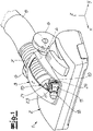
- a vacuum cleaner nozzle according to the invention is shown according to one exemplary embodiment.
- This includes a housing which consists of a housing chassis 2 and a cover 3 is assembled.
- a coupling piece 4 is arranged that is pivotably mounted about a pivot axis running in a transverse direction y.
- Two support rollers 6 are also arranged on the coupling piece 4 .
- the suction connection piece 5 is connected to the housing 1 by means of a corrugated hose 7 .
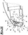
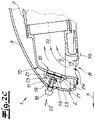
- the air flow inside the housing is shown in the sectional views 2A to 2C. It can be seen there that a suction mouth 8 is arranged on the underside of the housing 1 and is fluidically connected to the suction connection piece 5 via the corrugated hose 7 . Furthermore, a secondary air duct is formed within the housing 1 under the cover 3 . For this purpose, an opening 10 is formed within a suction channel 9 which connects the suction mouth 8 to the suction connection piece 5 . Furthermore, a flap arranged movably within the housing 1 is provided. The flow cross section of the secondary air duct can be adjusted by the distance s between the flap 11 and the opening 10 .
- Figure 2B a half-closed position.
- the distance s between the flap 11 and the opening 10 is reduced here, so that only a reduced secondary air flow 12 can enter the suction channel.
- Figure 2C shows a fully closed position with the gap wide is closed that no or no significant secondary air fractions get into the suction channel 9.
- the suction channel 9 has a collection chamber 13 arranged above the suction mouth 8 and a tubular section 14 running in the longitudinal direction/working direction (x) of the vacuum cleaner nozzle.
- the tubular section 14 simultaneously forms the connection area for the corrugated hose 7 .
- the collection space 13 and the tubular section 14 are connected to one another by a dome 15 .
- the opening 10 is arranged on the dome 15 opposite the tubular section 14 . As indicated by the flow arrows, this results in a particularly low-turbulence confluence of the secondary air flow 12 with the cleaning air flow 16 entering through the suction mouth 8.
- the suction channel 9 is designed in several parts in the exemplary embodiment.
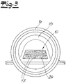
- the dome 15 and the tubular portion 14 forming component is separately in the 3 shown.
- the figure shows a rear view looking forward in the working direction x. It can be clearly seen that the opening 10 has an overall trapezoidal shape, which is mirror-symmetrical with respect to the longitudinal center plane of the floor nozzle of the vacuum cleaner and is designed with a longer lower edge and an upper edge that is shortened in comparison.
- the opening 10 is also divided into several areas by several webs 17 .
- the flap 11 can be moved by an operating element arranged on the outside of the housing 1 .
- the operating element is in the form of a rotary knob 18 . If one in particular in the Figures 2A to 2C can see, the mobility is provided by a spindle drive.
- the knob 18 is formed with an extension 19 on which an external thread is arranged. The external thread engages in an associated internal thread 20 of the flap 11 . By turning the knob 18, the distance s between the flap 11 and the opening 10 can be adjusted.
- the flap 11 is linearly positively guided on the suction channel 9 by projections 21 in the displacement direction 22 .
- Latching elements 23 at the ends of the projections 21 prevent the flap 11 from falling out of the restraint.
- an elastic plastic molded body 24 is arranged between the flap 11 and the opening 10 .
- This is designed as an open-pored foam body through which air can flow.
- the elastic molded body 24 is bonded over its entire surface to the inside of the flap 11 facing the suction channel 9 . Furthermore, the open-pored foam body 24 finds support in the webs 17 within the opening 10.
Landscapes
- Engineering & Computer Science (AREA)
- Mechanical Engineering (AREA)
- Nozzles For Electric Vacuum Cleaners (AREA)
Claims (12)
- Suceur d'aspirateur, notamment suceur de sol statique pour aspirateur, doté d'un corps (1), d'une bouche d'aspiration (8) placée sur la face inférieure du corps (1), d'une tubulure de raccordement (5) d'aspiration, destinée à être raccordée sur un conduit d'aspiration, d'une canalisation d'aspiration (9), laquelle relie la bouche d'aspiration (8) avec la tubulure de raccordement (5) et d'un guidage d'air auxiliaire, le guidage d'air auxiliaire comportant un orifice (10) conçu dans la canalisation d'aspiration (9) et un clapet (11) placé de manière mobile à l'intérieur du corps (1) et la section transversale de circulation du guidage d'air auxiliaire étant réglable par l'écart (s) entre le clapet (11) et l'orifice (10), caractérisé en ce qu'entre le clapet (11) et l'orifice (10) est placé un corps moulé (24) élastique en matière plastique.
- Suceur d'aspirateur selon la revendication 1, caractérisé en ce que la canalisation d'aspiration (9) comporte un espace collecteur (13), placé au-dessus de la bouche d'aspiration (8) ainsi qu'un tronçon (14) tubulaire s'écoulant dans la direction longitudinale (x) du suceur d'aspirateur, en ce que l'espace collecteur (13) et le tronçon (14) tubulaire sont reliés l'un à l'autre par un mandrin (15) et en ce que l'orifice (10) est placé sur le mandrin (15), au vis-à-vis du tronçon (14) tubulaire.
- Suceur d'aspirateur selon la revendication 1 ou 2, caractérisé en ce que l'orifice (10) est conçu de forme trapézoïdale.
- Suceur d'aspirateur selon l'une quelconque des revendications 1 à 3, caractérisé en ce que le clapet (11) est mobile via un élément de manœuvre placé sur la face extérieure du suceur d'aspirateur.
- Suceur d'aspirateur selon la revendication 4, caractérisé en ce que l'élément de manœuvre est réalisé sous la forme d'un bouton rotatif (18) ou d'une manette rotative.
- Suceur d'aspirateur selon l'une quelconque des revendications 1 à 5, caractérisé en ce que le clapet (11) est mobile via un mécanisme à vis (19, 20).
- Suceur d'aspirateur selon l'une quelconque des revendications 1 à 6, caractérisé en ce que le clapet (11) est guidé en déplacement longitudinal sur des systèmes de guidage (21) du suceur d'aspirateur, notamment de la canalisation d'aspiration (9).
- Suceur d'aspirateur selon la revendication 7, caractérisé en ce que les systèmes de guidage (21) sont surmoulés en monobloc sous la forme de saillies sur la canalisation d'aspiration (9).
- Suceur d'aspirateur selon l'une quelconque des revendications 1 à 6, caractérisé en ce que le clapet (11) est conçu de manière pivotante.
- Suceur d'aspirateur selon l'une quelconque des revendications 1 à 9, caractérisé en ce que le corps moulé (24) en matière plastique est relié, notamment collé avec le clapet (11).
- Suceur d'aspirateur selon l'une quelconque des revendications 1 à 10, caractérisé en ce que le corps moulé (24) en matière plastique est conçu en mousse à pores ouverts.
- Suceur d'aspirateur selon l'une quelconque des revendications 1 à 11, caractérisé en ce que l'orifice (10) est divisé par des barrettes (17) en plusieurs orifices partiels.
Applications Claiming Priority (1)
| Application Number | Priority Date | Filing Date | Title |
|---|---|---|---|
| DE102018133540.7A DE102018133540A1 (de) | 2018-12-21 | 2018-12-21 | Staubsaugerdüse, insbesondere statische Staubsaugerbodendüse |
Publications (2)
| Publication Number | Publication Date |
|---|---|
| EP3669732A1 EP3669732A1 (fr) | 2020-06-24 |
| EP3669732B1 true EP3669732B1 (fr) | 2022-10-19 |
Family
ID=67850968
Family Applications (1)
| Application Number | Title | Priority Date | Filing Date |
|---|---|---|---|
| EP19195220.9A Active EP3669732B1 (fr) | 2018-12-21 | 2019-09-03 | Buse d'aspirateur, en particulier buse d'aspirateur statique |
Country Status (2)
| Country | Link |
|---|---|
| EP (1) | EP3669732B1 (fr) |
| DE (1) | DE102018133540A1 (fr) |
Families Citing this family (1)
| Publication number | Priority date | Publication date | Assignee | Title |
|---|---|---|---|---|
| DE102022115600A1 (de) | 2022-06-22 | 2023-12-28 | Wessel-Werk Gmbh | Staubsaugerdüse |
Family Cites Families (9)
| Publication number | Priority date | Publication date | Assignee | Title |
|---|---|---|---|---|
| DE1844732U (de) * | 1961-10-19 | 1962-01-11 | Herbert Schmidt | Mundstueck fuer staubsauger. |
| DE7825557U1 (de) * | 1978-08-28 | 1979-08-23 | Siemens Ag, 1000 Berlin Und 8000 Muenchen | Staubsauger mit einer ueber ein saugrohr angeschlossenen saugduese |
| DE2923193A1 (de) * | 1979-06-08 | 1980-12-11 | Mauz & Pfeiffer Progress | Saugduese fuer einen staubsauger o.dgl. |
| DE29621116U1 (de) * | 1996-12-05 | 1997-02-13 | Wessel-Werk GmbH, 51580 Reichshof | Saugkopf für einen Staubsauger |
| DE19851405C2 (de) * | 1998-11-07 | 2003-04-03 | Wessel Werk Gmbh | Zusatzvorrichtung für statische Staubsaugerdüsen |
| DE19907580A1 (de) | 1999-02-22 | 2000-08-31 | Miele & Cie | Staubsaugermundstück, wie Bodendüse o. dgl. mit einem Nebenluftventil |
| DE29923995U1 (de) | 1999-02-22 | 2001-08-02 | Miele & Cie. GmbH & Co., 33332 Gütersloh | Staubsaugermundstück, wie Bodendüse o.dgl. mit einem Nebenluftventil |
| GB2470406B (en) * | 2009-05-22 | 2012-04-11 | Dyson Technology Ltd | Attachment for vacuum cleaning appliance |
| WO2017136086A1 (fr) * | 2016-01-27 | 2017-08-10 | China Manufacturing And Brokerage, Inc. | Buse d'aspirateur motorisée à flux d'air secondaire introduit de manière sélective pour une utilisation sur des surfaces recouvertes de moquette |
-
2018
- 2018-12-21 DE DE102018133540.7A patent/DE102018133540A1/de not_active Ceased
-
2019
- 2019-09-03 EP EP19195220.9A patent/EP3669732B1/fr active Active
Also Published As
| Publication number | Publication date |
|---|---|
| EP3669732A1 (fr) | 2020-06-24 |
| DE102018133540A1 (de) | 2020-06-25 |
Similar Documents
| Publication | Publication Date | Title |
|---|---|---|
| EP2979602B1 (fr) | Filtre a air a retrolavage | |
| EP2037792B1 (fr) | Vanne à air additionnel | |
| EP2989953A1 (fr) | Utilisation d'une buse d'aspiration pouvant etre raccordee a un aspirateur pour aspirer une surface textile, une surface de sol dur dalle et une surface de sol dur lisse sans joint | |
| EP2923623B1 (fr) | Sac de filtre à poussière pour un aspirateur et aspirateur doté d'un sac de filtre à poussière | |
| EP2845530A1 (fr) | Appareil d'aspiration portable pour liquides ou mélanges liquide/air | |
| EP2918939B1 (fr) | Cartouche filtrante pour une hotte de sécurité et hotte de sécurité dotée d'au moins une cartouche filtrante | |
| DE20312952U1 (de) | Luftleitvorrichtung, insbesondere für den Innenraum von Fahrzeugen | |
| DE102015108157A1 (de) | Saugdüse für einen Staubsauger | |
| DE10105371A1 (de) | Saugkopf für Haushalts-Bodenstaubsauger | |
| EP3500145B1 (fr) | Suceur pour un aspirateur, procédé d'aspiration de surfaces textiles et aspirateur | |
| EP3669732A1 (fr) | Buse d'aspirateur, en particulier buse d'aspirateur statique | |
| EP4212080B1 (fr) | Sac filtrant pour un aspirateur | |
| EP3050475A1 (fr) | Buse d'aspiration pour surfaces dures | |
| DE102017118487B4 (de) | Saugdüse für ein ein Sauggebläse aufweisendes Reinigungsgerät | |
| EP1620611B1 (fr) | Dispositif de fixation d'une paroi coulissante | |
| EP3639715B1 (fr) | Buse de sol pour un aspirateur | |
| EP1714734B1 (fr) | Dispositif démontable d'aspiration de poussière pour outil, avec système d'admission coulissant | |
| EP2123204B1 (fr) | Dispositif de régulation du flux d'air aspiré d'un aspirateur | |
| EP3763271B1 (fr) | Suceur pour un dispositif d'aspiration pour le nettoyage et l'entretien des sols. | |
| DE19851405C2 (de) | Zusatzvorrichtung für statische Staubsaugerdüsen | |
| EP3741276B1 (fr) | Aspirateur destiné au nettoyage des sols | |
| DE202019101089U1 (de) | Vorrichtung zum Absaugen von Luft | |
| DE102016100122A1 (de) | Bodendüse für einen Staubsauger, Staubsauger und Verfahren zur Herstellung einer Bodendüse für einen Staubsauger | |
| DE102005059275B4 (de) | Verblendungsvorrichtung für Fahrzeugdachsysteme mit öffnungsfähigem Deckel | |
| DE10313396A1 (de) | Hochdruckreinigungsgerät für im wesentlichen ebene Flächen |
Legal Events
| Date | Code | Title | Description |
|---|---|---|---|
| PUAI | Public reference made under article 153(3) epc to a published international application that has entered the european phase |
Free format text: ORIGINAL CODE: 0009012 |
|
| STAA | Information on the status of an ep patent application or granted ep patent |
Free format text: STATUS: REQUEST FOR EXAMINATION WAS MADE |
|
| 17P | Request for examination filed |
Effective date: 20200327 |
|
| AK | Designated contracting states |
Kind code of ref document: A1 Designated state(s): AL AT BE BG CH CY CZ DE DK EE ES FI FR GB GR HR HU IE IS IT LI LT LU LV MC MK MT NL NO PL PT RO RS SE SI SK SM TR |
|
| AX | Request for extension of the european patent |
Extension state: BA ME |
|
| GRAP | Despatch of communication of intention to grant a patent |
Free format text: ORIGINAL CODE: EPIDOSNIGR1 |
|
| STAA | Information on the status of an ep patent application or granted ep patent |
Free format text: STATUS: GRANT OF PATENT IS INTENDED |
|
| RIC1 | Information provided on ipc code assigned before grant |
Ipc: A47L 9/02 20060101AFI20220318BHEP |
|
| GRAS | Grant fee paid |
Free format text: ORIGINAL CODE: EPIDOSNIGR3 |
|
| INTG | Intention to grant announced |
Effective date: 20220412 |
|
| GRAA | (expected) grant |
Free format text: ORIGINAL CODE: 0009210 |
|
| STAA | Information on the status of an ep patent application or granted ep patent |
Free format text: STATUS: THE PATENT HAS BEEN GRANTED |
|
| AK | Designated contracting states |
Kind code of ref document: B1 Designated state(s): AL AT BE BG CH CY CZ DE DK EE ES FI FR GB GR HR HU IE IS IT LI LT LU LV MC MK MT NL NO PL PT RO RS SE SI SK SM TR |
|
| REG | Reference to a national code |
Ref country code: GB Ref legal event code: FG4D Free format text: NOT ENGLISH |
|
| REG | Reference to a national code |
Ref country code: CH Ref legal event code: EP |
|
| REG | Reference to a national code |
Ref country code: IE Ref legal event code: FG4D Free format text: LANGUAGE OF EP DOCUMENT: GERMAN |
|
| REG | Reference to a national code |
Ref country code: DE Ref legal event code: R096 Ref document number: 502019005957 Country of ref document: DE |
|
| REG | Reference to a national code |
Ref country code: AT Ref legal event code: REF Ref document number: 1525037 Country of ref document: AT Kind code of ref document: T Effective date: 20221115 |
|
| REG | Reference to a national code |
Ref country code: LT Ref legal event code: MG9D |
|
| REG | Reference to a national code |
Ref country code: NL Ref legal event code: MP Effective date: 20221019 |
|
| PG25 | Lapsed in a contracting state [announced via postgrant information from national office to epo] |
Ref country code: NL Free format text: LAPSE BECAUSE OF FAILURE TO SUBMIT A TRANSLATION OF THE DESCRIPTION OR TO PAY THE FEE WITHIN THE PRESCRIBED TIME-LIMIT Effective date: 20221019 |
|
| PG25 | Lapsed in a contracting state [announced via postgrant information from national office to epo] |
Ref country code: SE Free format text: LAPSE BECAUSE OF FAILURE TO SUBMIT A TRANSLATION OF THE DESCRIPTION OR TO PAY THE FEE WITHIN THE PRESCRIBED TIME-LIMIT Effective date: 20221019 Ref country code: PT Free format text: LAPSE BECAUSE OF FAILURE TO SUBMIT A TRANSLATION OF THE DESCRIPTION OR TO PAY THE FEE WITHIN THE PRESCRIBED TIME-LIMIT Effective date: 20230220 Ref country code: NO Free format text: LAPSE BECAUSE OF FAILURE TO SUBMIT A TRANSLATION OF THE DESCRIPTION OR TO PAY THE FEE WITHIN THE PRESCRIBED TIME-LIMIT Effective date: 20230119 Ref country code: LT Free format text: LAPSE BECAUSE OF FAILURE TO SUBMIT A TRANSLATION OF THE DESCRIPTION OR TO PAY THE FEE WITHIN THE PRESCRIBED TIME-LIMIT Effective date: 20221019 Ref country code: FI Free format text: LAPSE BECAUSE OF FAILURE TO SUBMIT A TRANSLATION OF THE DESCRIPTION OR TO PAY THE FEE WITHIN THE PRESCRIBED TIME-LIMIT Effective date: 20221019 Ref country code: ES Free format text: LAPSE BECAUSE OF FAILURE TO SUBMIT A TRANSLATION OF THE DESCRIPTION OR TO PAY THE FEE WITHIN THE PRESCRIBED TIME-LIMIT Effective date: 20221019 |
|
| PG25 | Lapsed in a contracting state [announced via postgrant information from national office to epo] |
Ref country code: RS Free format text: LAPSE BECAUSE OF FAILURE TO SUBMIT A TRANSLATION OF THE DESCRIPTION OR TO PAY THE FEE WITHIN THE PRESCRIBED TIME-LIMIT Effective date: 20221019 Ref country code: PL Free format text: LAPSE BECAUSE OF FAILURE TO SUBMIT A TRANSLATION OF THE DESCRIPTION OR TO PAY THE FEE WITHIN THE PRESCRIBED TIME-LIMIT Effective date: 20221019 Ref country code: LV Free format text: LAPSE BECAUSE OF FAILURE TO SUBMIT A TRANSLATION OF THE DESCRIPTION OR TO PAY THE FEE WITHIN THE PRESCRIBED TIME-LIMIT Effective date: 20221019 Ref country code: IS Free format text: LAPSE BECAUSE OF FAILURE TO SUBMIT A TRANSLATION OF THE DESCRIPTION OR TO PAY THE FEE WITHIN THE PRESCRIBED TIME-LIMIT Effective date: 20230219 Ref country code: HR Free format text: LAPSE BECAUSE OF FAILURE TO SUBMIT A TRANSLATION OF THE DESCRIPTION OR TO PAY THE FEE WITHIN THE PRESCRIBED TIME-LIMIT Effective date: 20221019 Ref country code: GR Free format text: LAPSE BECAUSE OF FAILURE TO SUBMIT A TRANSLATION OF THE DESCRIPTION OR TO PAY THE FEE WITHIN THE PRESCRIBED TIME-LIMIT Effective date: 20230120 |
|
| REG | Reference to a national code |
Ref country code: DE Ref legal event code: R097 Ref document number: 502019005957 Country of ref document: DE |
|
| PG25 | Lapsed in a contracting state [announced via postgrant information from national office to epo] |
Ref country code: SM Free format text: LAPSE BECAUSE OF FAILURE TO SUBMIT A TRANSLATION OF THE DESCRIPTION OR TO PAY THE FEE WITHIN THE PRESCRIBED TIME-LIMIT Effective date: 20221019 Ref country code: RO Free format text: LAPSE BECAUSE OF FAILURE TO SUBMIT A TRANSLATION OF THE DESCRIPTION OR TO PAY THE FEE WITHIN THE PRESCRIBED TIME-LIMIT Effective date: 20221019 Ref country code: EE Free format text: LAPSE BECAUSE OF FAILURE TO SUBMIT A TRANSLATION OF THE DESCRIPTION OR TO PAY THE FEE WITHIN THE PRESCRIBED TIME-LIMIT Effective date: 20221019 Ref country code: DK Free format text: LAPSE BECAUSE OF FAILURE TO SUBMIT A TRANSLATION OF THE DESCRIPTION OR TO PAY THE FEE WITHIN THE PRESCRIBED TIME-LIMIT Effective date: 20221019 Ref country code: CZ Free format text: LAPSE BECAUSE OF FAILURE TO SUBMIT A TRANSLATION OF THE DESCRIPTION OR TO PAY THE FEE WITHIN THE PRESCRIBED TIME-LIMIT Effective date: 20221019 |
|
| PLBE | No opposition filed within time limit |
Free format text: ORIGINAL CODE: 0009261 |
|
| STAA | Information on the status of an ep patent application or granted ep patent |
Free format text: STATUS: NO OPPOSITION FILED WITHIN TIME LIMIT |
|
| PG25 | Lapsed in a contracting state [announced via postgrant information from national office to epo] |
Ref country code: SK Free format text: LAPSE BECAUSE OF FAILURE TO SUBMIT A TRANSLATION OF THE DESCRIPTION OR TO PAY THE FEE WITHIN THE PRESCRIBED TIME-LIMIT Effective date: 20221019 Ref country code: AL Free format text: LAPSE BECAUSE OF FAILURE TO SUBMIT A TRANSLATION OF THE DESCRIPTION OR TO PAY THE FEE WITHIN THE PRESCRIBED TIME-LIMIT Effective date: 20221019 |
|
| 26N | No opposition filed |
Effective date: 20230720 |
|
| PG25 | Lapsed in a contracting state [announced via postgrant information from national office to epo] |
Ref country code: SI Free format text: LAPSE BECAUSE OF FAILURE TO SUBMIT A TRANSLATION OF THE DESCRIPTION OR TO PAY THE FEE WITHIN THE PRESCRIBED TIME-LIMIT Effective date: 20221019 |
|
| REG | Reference to a national code |
Ref country code: CH Ref legal event code: PL |
|
| PG25 | Lapsed in a contracting state [announced via postgrant information from national office to epo] |
Ref country code: LU Free format text: LAPSE BECAUSE OF NON-PAYMENT OF DUE FEES Effective date: 20230903 |
|
| REG | Reference to a national code |
Ref country code: BE Ref legal event code: MM Effective date: 20230930 |
|
| GBPC | Gb: european patent ceased through non-payment of renewal fee |
Effective date: 20230903 |
|
| PG25 | Lapsed in a contracting state [announced via postgrant information from national office to epo] |
Ref country code: LU Free format text: LAPSE BECAUSE OF NON-PAYMENT OF DUE FEES Effective date: 20230903 Ref country code: MC Free format text: LAPSE BECAUSE OF FAILURE TO SUBMIT A TRANSLATION OF THE DESCRIPTION OR TO PAY THE FEE WITHIN THE PRESCRIBED TIME-LIMIT Effective date: 20221019 |
|
| REG | Reference to a national code |
Ref country code: IE Ref legal event code: MM4A |
|
| PG25 | Lapsed in a contracting state [announced via postgrant information from national office to epo] |
Ref country code: IE Free format text: LAPSE BECAUSE OF NON-PAYMENT OF DUE FEES Effective date: 20230903 |
|
| PG25 | Lapsed in a contracting state [announced via postgrant information from national office to epo] |
Ref country code: GB Free format text: LAPSE BECAUSE OF NON-PAYMENT OF DUE FEES Effective date: 20230903 |
|
| PG25 | Lapsed in a contracting state [announced via postgrant information from national office to epo] |
Ref country code: CH Free format text: LAPSE BECAUSE OF NON-PAYMENT OF DUE FEES Effective date: 20230930 |
|
| PG25 | Lapsed in a contracting state [announced via postgrant information from national office to epo] |
Ref country code: IE Free format text: LAPSE BECAUSE OF NON-PAYMENT OF DUE FEES Effective date: 20230903 Ref country code: GB Free format text: LAPSE BECAUSE OF NON-PAYMENT OF DUE FEES Effective date: 20230903 Ref country code: CH Free format text: LAPSE BECAUSE OF NON-PAYMENT OF DUE FEES Effective date: 20230930 |
|
| PG25 | Lapsed in a contracting state [announced via postgrant information from national office to epo] |
Ref country code: BE Free format text: LAPSE BECAUSE OF NON-PAYMENT OF DUE FEES Effective date: 20230930 |
|
| PGFP | Annual fee paid to national office [announced via postgrant information from national office to epo] |
Ref country code: IT Payment date: 20240924 Year of fee payment: 6 |
|
| PG25 | Lapsed in a contracting state [announced via postgrant information from national office to epo] |
Ref country code: BG Free format text: LAPSE BECAUSE OF FAILURE TO SUBMIT A TRANSLATION OF THE DESCRIPTION OR TO PAY THE FEE WITHIN THE PRESCRIBED TIME-LIMIT Effective date: 20221019 |
|
| PG25 | Lapsed in a contracting state [announced via postgrant information from national office to epo] |
Ref country code: BG Free format text: LAPSE BECAUSE OF FAILURE TO SUBMIT A TRANSLATION OF THE DESCRIPTION OR TO PAY THE FEE WITHIN THE PRESCRIBED TIME-LIMIT Effective date: 20221019 |
|
| PG25 | Lapsed in a contracting state [announced via postgrant information from national office to epo] |
Ref country code: CY Free format text: LAPSE BECAUSE OF FAILURE TO SUBMIT A TRANSLATION OF THE DESCRIPTION OR TO PAY THE FEE WITHIN THE PRESCRIBED TIME-LIMIT; INVALID AB INITIO Effective date: 20190903 |
|
| PG25 | Lapsed in a contracting state [announced via postgrant information from national office to epo] |
Ref country code: HU Free format text: LAPSE BECAUSE OF FAILURE TO SUBMIT A TRANSLATION OF THE DESCRIPTION OR TO PAY THE FEE WITHIN THE PRESCRIBED TIME-LIMIT; INVALID AB INITIO Effective date: 20190903 |
|
| PGFP | Annual fee paid to national office [announced via postgrant information from national office to epo] |
Ref country code: DE Payment date: 20250910 Year of fee payment: 7 |
|
| PGFP | Annual fee paid to national office [announced via postgrant information from national office to epo] |
Ref country code: FR Payment date: 20250922 Year of fee payment: 7 |
|
| REG | Reference to a national code |
Ref country code: AT Ref legal event code: MM01 Ref document number: 1525037 Country of ref document: AT Kind code of ref document: T Effective date: 20240903 |
|
| PG25 | Lapsed in a contracting state [announced via postgrant information from national office to epo] |
Ref country code: TR Free format text: LAPSE BECAUSE OF FAILURE TO SUBMIT A TRANSLATION OF THE DESCRIPTION OR TO PAY THE FEE WITHIN THE PRESCRIBED TIME-LIMIT Effective date: 20221019 |
|
| PG25 | Lapsed in a contracting state [announced via postgrant information from national office to epo] |
Ref country code: AT Free format text: LAPSE BECAUSE OF NON-PAYMENT OF DUE FEES Effective date: 20240903 |
|
| PGFP | Annual fee paid to national office [announced via postgrant information from national office to epo] |
Ref country code: AT Payment date: 20260410 Year of fee payment: 5 |
|
| PG25 | Lapsed in a contracting state [announced via postgrant information from national office to epo] |
Ref country code: IT Free format text: LAPSE BECAUSE OF NON-PAYMENT OF DUE FEES Effective date: 20250903 |