EP3669823A1 - Dispositif de filtre - Google Patents
Dispositif de filtre Download PDFInfo
- Publication number
- EP3669823A1 EP3669823A1 EP18846869.8A EP18846869A EP3669823A1 EP 3669823 A1 EP3669823 A1 EP 3669823A1 EP 18846869 A EP18846869 A EP 18846869A EP 3669823 A1 EP3669823 A1 EP 3669823A1
- Authority
- EP
- European Patent Office
- Prior art keywords
- filter device
- filtering
- stent
- retrieving
- constraining
- Prior art date
- Legal status (The legal status is an assumption and is not a legal conclusion. Google has not performed a legal analysis and makes no representation as to the accuracy of the status listed.)
- Granted
Links
Images


Classifications
-
- A—HUMAN NECESSITIES
- A61—MEDICAL OR VETERINARY SCIENCE; HYGIENE
- A61F—FILTERS IMPLANTABLE INTO BLOOD VESSELS; PROSTHESES; DEVICES PROVIDING PATENCY TO, OR PREVENTING COLLAPSING OF, TUBULAR STRUCTURES OF THE BODY, e.g. STENTS; ORTHOPAEDIC, NURSING OR CONTRACEPTIVE DEVICES; FOMENTATION; TREATMENT OR PROTECTION OF EYES OR EARS; BANDAGES, DRESSINGS OR ABSORBENT PADS; FIRST-AID KITS
- A61F2/00—Filters implantable into blood vessels; Prostheses, i.e. artificial substitutes or replacements for parts of the body; Appliances for connecting them with the body; Devices providing patency to, or preventing collapsing of, tubular structures of the body, e.g. stents
- A61F2/01—Filters implantable into blood vessels
- A61F2/0105—Open ended, i.e. legs gathered only at one side
-
- A—HUMAN NECESSITIES
- A61—MEDICAL OR VETERINARY SCIENCE; HYGIENE
- A61F—FILTERS IMPLANTABLE INTO BLOOD VESSELS; PROSTHESES; DEVICES PROVIDING PATENCY TO, OR PREVENTING COLLAPSING OF, TUBULAR STRUCTURES OF THE BODY, e.g. STENTS; ORTHOPAEDIC, NURSING OR CONTRACEPTIVE DEVICES; FOMENTATION; TREATMENT OR PROTECTION OF EYES OR EARS; BANDAGES, DRESSINGS OR ABSORBENT PADS; FIRST-AID KITS
- A61F2/00—Filters implantable into blood vessels; Prostheses, i.e. artificial substitutes or replacements for parts of the body; Appliances for connecting them with the body; Devices providing patency to, or preventing collapsing of, tubular structures of the body, e.g. stents
- A61F2/01—Filters implantable into blood vessels
- A61F2/0108—Both ends closed, i.e. legs gathered at both ends
-
- A—HUMAN NECESSITIES
- A61—MEDICAL OR VETERINARY SCIENCE; HYGIENE
- A61F—FILTERS IMPLANTABLE INTO BLOOD VESSELS; PROSTHESES; DEVICES PROVIDING PATENCY TO, OR PREVENTING COLLAPSING OF, TUBULAR STRUCTURES OF THE BODY, e.g. STENTS; ORTHOPAEDIC, NURSING OR CONTRACEPTIVE DEVICES; FOMENTATION; TREATMENT OR PROTECTION OF EYES OR EARS; BANDAGES, DRESSINGS OR ABSORBENT PADS; FIRST-AID KITS
- A61F2/00—Filters implantable into blood vessels; Prostheses, i.e. artificial substitutes or replacements for parts of the body; Appliances for connecting them with the body; Devices providing patency to, or preventing collapsing of, tubular structures of the body, e.g. stents
- A61F2/02—Prostheses implantable into the body
- A61F2/04—Hollow or tubular parts of organs, e.g. bladders, tracheae, bronchi or bile ducts
-
- A—HUMAN NECESSITIES
- A61—MEDICAL OR VETERINARY SCIENCE; HYGIENE
- A61F—FILTERS IMPLANTABLE INTO BLOOD VESSELS; PROSTHESES; DEVICES PROVIDING PATENCY TO, OR PREVENTING COLLAPSING OF, TUBULAR STRUCTURES OF THE BODY, e.g. STENTS; ORTHOPAEDIC, NURSING OR CONTRACEPTIVE DEVICES; FOMENTATION; TREATMENT OR PROTECTION OF EYES OR EARS; BANDAGES, DRESSINGS OR ABSORBENT PADS; FIRST-AID KITS
- A61F2/00—Filters implantable into blood vessels; Prostheses, i.e. artificial substitutes or replacements for parts of the body; Appliances for connecting them with the body; Devices providing patency to, or preventing collapsing of, tubular structures of the body, e.g. stents
- A61F2/82—Devices providing patency to, or preventing collapsing of, tubular structures of the body, e.g. stents
- A61F2/86—Stents in a form characterised by the wire-like elements; Stents in the form characterised by a net-like or mesh-like structure
-
- A—HUMAN NECESSITIES
- A61—MEDICAL OR VETERINARY SCIENCE; HYGIENE
- A61F—FILTERS IMPLANTABLE INTO BLOOD VESSELS; PROSTHESES; DEVICES PROVIDING PATENCY TO, OR PREVENTING COLLAPSING OF, TUBULAR STRUCTURES OF THE BODY, e.g. STENTS; ORTHOPAEDIC, NURSING OR CONTRACEPTIVE DEVICES; FOMENTATION; TREATMENT OR PROTECTION OF EYES OR EARS; BANDAGES, DRESSINGS OR ABSORBENT PADS; FIRST-AID KITS
- A61F2/00—Filters implantable into blood vessels; Prostheses, i.e. artificial substitutes or replacements for parts of the body; Appliances for connecting them with the body; Devices providing patency to, or preventing collapsing of, tubular structures of the body, e.g. stents
- A61F2/01—Filters implantable into blood vessels
- A61F2/011—Instruments for their placement or removal
-
- A—HUMAN NECESSITIES
- A61—MEDICAL OR VETERINARY SCIENCE; HYGIENE
- A61F—FILTERS IMPLANTABLE INTO BLOOD VESSELS; PROSTHESES; DEVICES PROVIDING PATENCY TO, OR PREVENTING COLLAPSING OF, TUBULAR STRUCTURES OF THE BODY, e.g. STENTS; ORTHOPAEDIC, NURSING OR CONTRACEPTIVE DEVICES; FOMENTATION; TREATMENT OR PROTECTION OF EYES OR EARS; BANDAGES, DRESSINGS OR ABSORBENT PADS; FIRST-AID KITS
- A61F2/00—Filters implantable into blood vessels; Prostheses, i.e. artificial substitutes or replacements for parts of the body; Appliances for connecting them with the body; Devices providing patency to, or preventing collapsing of, tubular structures of the body, e.g. stents
- A61F2/01—Filters implantable into blood vessels
- A61F2002/016—Filters implantable into blood vessels made from wire-like elements
-
- A—HUMAN NECESSITIES
- A61—MEDICAL OR VETERINARY SCIENCE; HYGIENE
- A61F—FILTERS IMPLANTABLE INTO BLOOD VESSELS; PROSTHESES; DEVICES PROVIDING PATENCY TO, OR PREVENTING COLLAPSING OF, TUBULAR STRUCTURES OF THE BODY, e.g. STENTS; ORTHOPAEDIC, NURSING OR CONTRACEPTIVE DEVICES; FOMENTATION; TREATMENT OR PROTECTION OF EYES OR EARS; BANDAGES, DRESSINGS OR ABSORBENT PADS; FIRST-AID KITS
- A61F2/00—Filters implantable into blood vessels; Prostheses, i.e. artificial substitutes or replacements for parts of the body; Appliances for connecting them with the body; Devices providing patency to, or preventing collapsing of, tubular structures of the body, e.g. stents
- A61F2/01—Filters implantable into blood vessels
- A61F2002/018—Filters implantable into blood vessels made from tubes or sheets of material, e.g. by etching or laser-cutting
-
- A—HUMAN NECESSITIES
- A61—MEDICAL OR VETERINARY SCIENCE; HYGIENE
- A61F—FILTERS IMPLANTABLE INTO BLOOD VESSELS; PROSTHESES; DEVICES PROVIDING PATENCY TO, OR PREVENTING COLLAPSING OF, TUBULAR STRUCTURES OF THE BODY, e.g. STENTS; ORTHOPAEDIC, NURSING OR CONTRACEPTIVE DEVICES; FOMENTATION; TREATMENT OR PROTECTION OF EYES OR EARS; BANDAGES, DRESSINGS OR ABSORBENT PADS; FIRST-AID KITS
- A61F2/00—Filters implantable into blood vessels; Prostheses, i.e. artificial substitutes or replacements for parts of the body; Appliances for connecting them with the body; Devices providing patency to, or preventing collapsing of, tubular structures of the body, e.g. stents
- A61F2/95—Instruments specially adapted for placement or removal of stents or stent-grafts
- A61F2002/9528—Instruments specially adapted for placement or removal of stents or stent-grafts for retrieval of stents
-
- A—HUMAN NECESSITIES
- A61—MEDICAL OR VETERINARY SCIENCE; HYGIENE
- A61F—FILTERS IMPLANTABLE INTO BLOOD VESSELS; PROSTHESES; DEVICES PROVIDING PATENCY TO, OR PREVENTING COLLAPSING OF, TUBULAR STRUCTURES OF THE BODY, e.g. STENTS; ORTHOPAEDIC, NURSING OR CONTRACEPTIVE DEVICES; FOMENTATION; TREATMENT OR PROTECTION OF EYES OR EARS; BANDAGES, DRESSINGS OR ABSORBENT PADS; FIRST-AID KITS
- A61F2210/00—Particular material properties of prostheses classified in groups A61F2/00 - A61F2/26 or A61F2/82 or A61F9/00 or A61F11/00 or subgroups thereof
- A61F2210/0004—Particular material properties of prostheses classified in groups A61F2/00 - A61F2/26 or A61F2/82 or A61F9/00 or A61F11/00 or subgroups thereof bioabsorbable
-
- A—HUMAN NECESSITIES
- A61—MEDICAL OR VETERINARY SCIENCE; HYGIENE
- A61F—FILTERS IMPLANTABLE INTO BLOOD VESSELS; PROSTHESES; DEVICES PROVIDING PATENCY TO, OR PREVENTING COLLAPSING OF, TUBULAR STRUCTURES OF THE BODY, e.g. STENTS; ORTHOPAEDIC, NURSING OR CONTRACEPTIVE DEVICES; FOMENTATION; TREATMENT OR PROTECTION OF EYES OR EARS; BANDAGES, DRESSINGS OR ABSORBENT PADS; FIRST-AID KITS
- A61F2220/00—Fixations or connections for prostheses classified in groups A61F2/00 - A61F2/26 or A61F2/82 or A61F9/00 or A61F11/00 or subgroups thereof
- A61F2220/0008—Fixation appliances for connecting prostheses to the body
- A61F2220/0016—Fixation appliances for connecting prostheses to the body with sharp anchoring protrusions, e.g. barbs, pins, spikes
-
- A—HUMAN NECESSITIES
- A61—MEDICAL OR VETERINARY SCIENCE; HYGIENE
- A61F—FILTERS IMPLANTABLE INTO BLOOD VESSELS; PROSTHESES; DEVICES PROVIDING PATENCY TO, OR PREVENTING COLLAPSING OF, TUBULAR STRUCTURES OF THE BODY, e.g. STENTS; ORTHOPAEDIC, NURSING OR CONTRACEPTIVE DEVICES; FOMENTATION; TREATMENT OR PROTECTION OF EYES OR EARS; BANDAGES, DRESSINGS OR ABSORBENT PADS; FIRST-AID KITS
- A61F2230/00—Geometry of prostheses classified in groups A61F2/00 - A61F2/26 or A61F2/82 or A61F9/00 or A61F11/00 or subgroups thereof
- A61F2230/0002—Two-dimensional shapes, e.g. cross-sections
- A61F2230/0028—Shapes in the form of latin or greek characters
- A61F2230/005—Rosette-shaped, e.g. star-shaped
-
- A—HUMAN NECESSITIES
- A61—MEDICAL OR VETERINARY SCIENCE; HYGIENE
- A61F—FILTERS IMPLANTABLE INTO BLOOD VESSELS; PROSTHESES; DEVICES PROVIDING PATENCY TO, OR PREVENTING COLLAPSING OF, TUBULAR STRUCTURES OF THE BODY, e.g. STENTS; ORTHOPAEDIC, NURSING OR CONTRACEPTIVE DEVICES; FOMENTATION; TREATMENT OR PROTECTION OF EYES OR EARS; BANDAGES, DRESSINGS OR ABSORBENT PADS; FIRST-AID KITS
- A61F2230/00—Geometry of prostheses classified in groups A61F2/00 - A61F2/26 or A61F2/82 or A61F9/00 or A61F11/00 or subgroups thereof
- A61F2230/0002—Two-dimensional shapes, e.g. cross-sections
- A61F2230/0028—Shapes in the form of latin or greek characters
- A61F2230/0054—V-shaped
-
- A—HUMAN NECESSITIES
- A61—MEDICAL OR VETERINARY SCIENCE; HYGIENE
- A61F—FILTERS IMPLANTABLE INTO BLOOD VESSELS; PROSTHESES; DEVICES PROVIDING PATENCY TO, OR PREVENTING COLLAPSING OF, TUBULAR STRUCTURES OF THE BODY, e.g. STENTS; ORTHOPAEDIC, NURSING OR CONTRACEPTIVE DEVICES; FOMENTATION; TREATMENT OR PROTECTION OF EYES OR EARS; BANDAGES, DRESSINGS OR ABSORBENT PADS; FIRST-AID KITS
- A61F2250/00—Special features of prostheses classified in groups A61F2/00 - A61F2/26 or A61F2/82 or A61F9/00 or A61F11/00 or subgroups thereof
- A61F2250/0058—Additional features; Implant or prostheses properties not otherwise provided for
- A61F2250/0059—Additional features; Implant or prostheses properties not otherwise provided for temporary
-
- A—HUMAN NECESSITIES
- A61—MEDICAL OR VETERINARY SCIENCE; HYGIENE
- A61F—FILTERS IMPLANTABLE INTO BLOOD VESSELS; PROSTHESES; DEVICES PROVIDING PATENCY TO, OR PREVENTING COLLAPSING OF, TUBULAR STRUCTURES OF THE BODY, e.g. STENTS; ORTHOPAEDIC, NURSING OR CONTRACEPTIVE DEVICES; FOMENTATION; TREATMENT OR PROTECTION OF EYES OR EARS; BANDAGES, DRESSINGS OR ABSORBENT PADS; FIRST-AID KITS
- A61F2310/00—Prostheses classified in A61F2/28 or A61F2/30 - A61F2/44 being constructed from or coated with a particular material
- A61F2310/00005—The prosthesis being constructed from a particular material
- A61F2310/00365—Proteins; Polypeptides; Degradation products thereof
Definitions
- the present invention relates to the technical field of medical instruments and, more specifically, to a filter device.
- VTE Venous Thrombo Embolism
- DVT Deep Vein Thrombosis
- PE Pulmonary Embolism
- VCF Vena Cava Filter
- retrievable VCFs have gradually become the mainstream, and filters can be retrieved from the patients after PE risk is removed, thereby avoiding complications caused by the implantation and long-term stay of filters.
- the actual retrieving probability of the retrievable filters in America is about 30%, that is, although most patients have been implanted with a retrievable filter, the filter is not actually retrieved. There are many reasons for this phenomenon. Some patients are reluctant to undergo a secondary surgery, and some patients fail to retrieve the filter successfully.
- filters that do not require secondary surgery, i.e., partially degradable filters.
- the principle of such kind of filter is that the head end of the filter is defined by a degradable filament to form a filter net.
- the head end of the filter is unfolded to fit with the vascular wall after the degradable filament is degraded in the blood vessel, and the filter becomes a tubular stent. In such way, it is not required to perform an additional retrieving operation for the filter, and the filter can convert into a stent to reduce the incidence rate of long-term complications caused by the filter.
- An objective of the present invention is to provide a filter device that can be not only retrieved within a preset time window but also partially degraded in the body beyond the preset time window, thereby reducing the risk of long-term complications after the filter is implanted in the human body.
- the present invention provides a filter device, comprising:
- the filter device has a head end and a tail end opposite to each other, the first end of the filtering part corresponds to the head end of the filter device, and the second end of the stent part corresponds to the tail end of the filter device.
- the stent part comprises a support part and a retrieving part when the connecting part is disposed at the second end of the stent part, and the second end of the stent part corresponds to the tail end of the filter device; one end of the support part is connected to the second end of the filtering part, and a further end of the support part or the one end of the support part is connected to one end of the retrieving part; and the one end of the support part serves as the first end of the stent part, a further end of the retrieving part serves as the second end of the stent part, and the further end of the retrieving part is constrained by the constraining part to form the tail end.
- the support part in an entire length thereof, is not overlapping with the filtering part in an axial direction of the filter device when the further end of the support part is connected to the one end of the retrieving part.
- the support part in a partial or an entire length thereof, is overlapping with the filtering part in an axial direction of the filter device when the one end of the support part is connected to the one end of the retrieving part.
- the retrieving part comprises a plurality of retrieving rods distributed along a circumferential direction of the support part, and one end of each of the plurality of retrieving rods is connected to the support part, and further ends of the plurality of retrieving rods are constrained together by the constraining part.
- the further ends of the plurality of retrieving rods are provided with a plurality of connecting holes
- the constraining part comprises a constraining body which passes through the plurality of connecting holes and is fixed.
- At least one end of the constraining body is fixed, and a further end of the constraining body passes through the plurality of connecting holes and then is connected to the one end of the constraining body.
- the stent part comprises a support part when the connecting part is disposed at the first end of the filtering part; the support part has one end connected to the second end of the filtering part, and a further end that is expanded.
- the support part in a partial or an entire length thereof, is overlapping with the filtering part in an axial direction of the filter device when the first end of the stent part corresponds to the tail end of the filter device.
- the support part in an entire length thereof, is not overlapping with the filtering part in an axial direction of the filter device when the second end of the stent part corresponds to the tail end of the filter device.
- the first end of the filtering part is provided with a plurality of connecting holes
- the constraining part comprises a constraining body which passes through the connecting holes and is fixed.
- At least one end of the constraining body is fixed, and a further end of the constraining body passes through the plurality of connecting holes and then is connected to the one end of the constraining body.
- the connecting part has a recessed space configured to engage with an external mechanism.
- the connecting part is a hook or a tube having a notch.
- the filter device includes a filtering part, a degradable constraining part, a stent part, and a connecting part.
- the filtering part has a first end and a second end opposite to each other.
- the constraining part is configured to at least constrain the first end of the filtering part.
- the stent part has a first end and a second end opposite to each other. The first end of the stent part is connected to the second end of the filtering part, and disposed coaxial with the filtering part.
- the connecting part is disposed on one or more of the first end of the filtering part and the second end of the stent part, and is configured to connect to an external mechanism, and the constraining part is further configured to constrain the second end of the stent part when the connecting part is disposed at the second end of the stent part.
- the filter device of such a structure can be taken out from the human body by means of the connecting part in the case that the patient does not require the protection provided by the filter device, and can be converted into a tubular stent by means of the degradable constraining part to establish a blood flow channel in the human body.
- the two operable modes on one hand can reduce the incidence rate of long-term complications such as vena cava blockage and perforation, and on the other hand avoid the secondary surgery and thus can alleviate the suffering of the patients.
- 10, 20, 30 respectively denote a filter device; 1, 1', 1" respectively denote a filtering part; 101 denotes a connecting hole; 2 denotes a constraining part; 201 denotes a binding filament; 3 denotes a support part; 301 denotes a barb; 4 denotes a connecting part; 5 denotes a retrieving part; 501 denotes a connecting hole; 502 denotes a retrieving rod.
- FIGs. 1-10 the filter device proposed by the present invention will be further described in detail below with reference to FIGs. 1-10 . It should be noted that the drawings are in a very simplified form and use non-precise proportions, and are only intended to conveniently and explicitly assist in describing the objectives of embodiments of the present invention.
- FIG. 1 is a schematic structural diagram of a filter device according to Embodiment 1 of the present invention.
- the filter device 10 includes a filtering part 1, a constraining part 2, a support part 3, and a connecting part 4.
- the filtering part 1 has a first end and a second end opposite to each other.
- the filter device 10 has a head end and a tail end opposite to each other.
- the first end corresponds to the head end and is generally one end adjacent to the heart, i.e., a proximal end.
- the support part 3 is used as a stent part in this embodiment and has a first end and a second end opposite to each other.
- the constraining part 2 is made of a biodegradable material that is constrained to the first end of the filtering part 1 to close the first end of the filtering part 1 so as to trap the thrombus.
- the second end of the filtering part 1 is connected to the first end of the support part 3.
- the filtering part 1 is formed as a filter net structure under the constraint of the constraining part 2, and the filter net structure may be conical and has the functions of filtering thrombus and preventing pulmonary embolism and the like. Moreover, after implanted into the human body for a period of time, the first end of the filtering part 1 is unbound and open after the constraining part 2 is completely degraded, and accordingly the function of filtering the thrombus is no longer provided.
- the support part 3 is tubular and disposed coaxial with the filtering part 1.
- the first end of the support part 3 is connected to the filtering part 1, and the second end of the support part 3 is open.
- the second end of the support part 3 corresponds to the tail end of the filter device 10, and the tail end is generally one end away from the heart, i.e., a distal end.
- the entire length of the support part 3 does not overlap with the filtering part 1 in the axial direction of the filter device 10.
- the filtering part 1 is located at one side of the support part 3 and does not overlap with the support part 3.
- the first end of the support part 3 has a first edge
- the second end of the support part 3 has a second edge
- the contours of the first edge and the second edge are not limited to a zigzag shape, a wave shape, or the like.
- the support part 3 can structurally support the filtering part 1, and can be centrally disposed in the blood vessel before the filtering part 1 loses the constraint from the constraining part 2, and can be fitted well with the vascular wall without causing displacement. Centering herein means that the filtering part 1 is located in the middle of the blood vessel, and its vertex (first end) is substantially on the central axis of the blood vessel.
- the first end of the filtering part 1 is provided with the connecting part 4.
- One end of the connecting part 4 is connected to the filtering part 1, and the other end of the connecting 4 is configured to connect an external mechanism.
- the filter device 10 can be pulled by the connecting part 4 when the connecting part 4 is connected to the external mechanism, and before the filtering part 1 loses the constraint from the constraining part 2, so that the filter device 10 enters a predetermined channel (e.g. a sheath) and then is taken out from the human body.
- a predetermined channel e.g. a sheath
- the filter device 10 can be selected to be taken out within a preset time window, and the preset time window is shorter than the time required for completely degrading the constraining part 2. More preferably, the preset time window is set to begin at the moment that the filter device 10 is implanted into the human body and end before the filter device 10 is fused to be integrated with the vascular wall. Specifically, the retrieving period, which begins at the moment that the filter device 10 is implanted into the human body and ends at the moment that the filter device 10 is fused to be integrated with the vascular wall, can be determined through tests, and the preset time window may be selected to be shorter than the retrieving period.
- the filter device 10 is converted into a tubular stent as a whole after the constraining part 2 is completely degraded.
- the first end of the filtering part 1 is open, and the second end of the support part 3 is also in an open state.
- the tubular filter device 10 can be fitted with the vascular wall to form a blood flow channel, thereby ensuring normal circulation of blood.
- the filter device 10 can only be retrieved through a jugular vein pathway.
- the first end of the filtering part 1 is close to the heart after being implanted into the human body.
- an external mechanism and the sheath are introduced through the jugular vein, and the filter device 10 is pulled into the sheath by connecting the external mechanism to the connecting part 4.
- the external mechanism can be a conventional surgical catcher.
- the filter device 10 of this embodiment is particularly suitable for patients requiring temporary protection from filter. There are two operation modes after the filter device 10 is implanted into the patient's body.
- the first operation mode is to completely take out the filter device 10 from the patient's body through an interventional surgery within a preset time window.
- the second operation mode is to partially degrade the filter device 10 in the patient's body beyond the preset time window (that is, the constraining part 2 is degraded) so that the filter device 10 no longer has a filtering function and is converted into a tubular stent.
- the filter device 10 Compared with the permanent filter, the filter device 10 provided by this embodiment can be taken out from the human body or converted into a tubular stent in the case that the patient does not require the protection from the filter device. Such two alternative modes can reduce the incidence rate of long-term complications such as vena cava blockage and perforation.
- the filter device 10 Compared with the retrievable filter, the filter device 10 provided by the present invention makes it possible to avoid the secondary surgery, and the filter device 10 is able to be converted into a tubular stent even if the filter device 10 cannot be taken out beyond the preset time window or due to other reasons, thereby reducing the incidence rate of various complications caused by long-term stay of the filter device 10.
- the time for the complete degradation of the constraining part 2 depends on many factors, including the molecular weight, crystallinity and hydrophilicity of the materials used, the volume of each component, the surface area, and environmental factors, etc., and the specific time for the complete degradation can be selected by those skilled in the art as needed.
- the time for the complete degradation of the constraining part 2 is the time when the constraining part 2 is implanted into the human body until the (main) physical property is completely lost. In this case, the constraining part 2 does not constrain the filtering part 1 at all.
- the constraining part 2 is specifically a degradable binding filament 201.
- the binding filament 201 is completely degraded within a predetermined period of time, so as to disconnect from the filtering part 1, thereby releasing the binding at the first end of the filtering part 1.
- the present invention includes, but is not limited to, a filament, and may also be a cord, wire, or the like.
- the binding filament 201 is fixedly disposed on the first end of the filtering part 1 to ensure that at least one end of the binding filament 201 can still be connected to the first end of the filtering part 1 after broken, thereby ensuring that the degradation residue of the binding filament 201 does not fall into the blood to cause an adverse event such as embolism.
- the residue is fitted with the vascular wall after the binding filament 201 is broken, and wrapped through the endothelialization formed gradually and then degraded in the tissue.
- the material of the binding filament 201 is selected from a degradable metal material such as a magnesium alloy, a pure iron, or a zinc alloy, or a degradable polymer material such as polylactic acid.
- the first end of the filtering part 1 can be provided with a plurality of connecting holes 101, and the other end of the binding filament 201 passes through the connecting holes 101 and constrains the first end of the filtering part 1 in a knotted manner, to constrain the connecting holes 101 of the filtering part 1 together so that the filtering part 1 is of a filter net structure.
- the filtering part 1 can be specifically formed by combining a plurality of structural bodies into a mesh structure.
- the structural body of the filtering part 1 can be a wire, a rod or a tube, and can be processed by laser cutting, weaving or the like.
- the connecting holes 101 are provided on a part or all of the structural bodies of the filtering part 1.
- the support part 3 is provided with barbs 301.
- the extension direction of the barbs 301 is consistent with the retrieving direction of the filter device 10.
- the barbs 301 are configured to penetrate the vascular tissue to fix the filter device 10.
- the barbs 301 can also be separated from the vascular tissue in the retrieving process.
- each of the barbs 301 is disposed on an edge of the support part 3 away from the filtering part 1, and preferably disposed on a node of the edge.
- the node is a position where a plurality of structural bodies intersect.
- the filtering part 1 is composed of a plurality of grid units in the same circumferential direction. Each grid unit is composed of a plurality of structural bodies connected end to end.
- the structural body of the filtering part 1 can also be a wire, a tube or a rod.
- FIG. 2a it is a schematic structural diagram of a filter device according to Embodiment 1 of the present invention under a projection from a head end to a tail end.
- the filtering part 1 is composed of a plurality of diamond-shaped units in the same circumferential direction, and the number of the diamond-shaped units is preferably 6-8. Alternatively, as shown in FIG.
- FIG. 2b it is a schematic structural diagram of a filter device according to Embodiment 1 of the present invention under a projection from the head end to the tail end.
- the filtering part 1 is composed of a plurality of fan-shaped units in the same circumferential direction, and the number of the fan-shaped units is preferably 12-16. Compared with the fan-shaped units, the diamond-shaped units filter the thrombus more evenly, and the thrombus filtering effect is better.
- the connecting part 4 has a recessed space configured to engage with the external mechanism.
- the connecting part 4 can be a hook.
- the connecting part 4 can also be a tube having a notch.
- the connecting part 4 and the filtering part 1 can be connected in the following manners.
- the first end of the support part 3 is connected to the filtering part 1 through preferably hot melting, and accordingly the fixing effect is better.
- the structural bodies of the support part 3 may be connected end to end to form a plurality of support units.
- the support units each can be hexagonal, diamond-shaped, etc., and can be fabricated by laser cutting.
- every two of the structural bodies of the support part 3 are intersected to form a plurality of support units.
- the shape of the support units is not limited, and the support units can be fabricated by weaving.
- the structural bodies of the support part 3 are arranged in groups of three and arranged in a Z-shape to form a plurality of support units.
- a part or all of the length of the support part 3 provided in this embodiment may also overlap with the filtering part 1" in the axial direction of the filter device 20 (this solution is not shown, and adaptive reference is made to FIG. 8 ).
- the first end of the support part 3 is connected to the second end of the filtering part 1".
- the first end of the support part 3 corresponds to the tail end of the filter device 20, that is, the second end of the support part 3 is folded at its first end and directed toward the first end of the filter part 1".
- the filter device 20 provided in this embodiment is basically the same as that in Embodiment 1, and the following description is provided only for describing the differences.
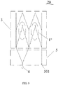
- FIG. 6 is a schematic structural diagram of a filter device according to Embodiment 2 of the present invention.
- the filter device 20 includes a filtering part 1, a constraining part 2, a support part 3, and a connecting part 4, and further includes a retrieving part 5.
- the support part 3 and the retrieving part 5 together constitute the stent part of the present invention.
- the stent part has a first end and a second end opposite to each other, and the second end of the stent part corresponds to the tail end of the filter device 20.
- the entire length of the support part 3 does not overlap with the filtering part 1 in the axial direction of the filter device 20.
- the first end of the support part 3 is connected to the second end of the filtering part 1, and the second end of the support part 3 is connected to one end of the retrieving part 5.
- the first end of the support part 3 serves as the first end of the stent part
- the other end of the retrieving part 5 serves as the second end of the stent part.
- the said other end of the retrieving part 5 is constrained by the constraining part 2 to form the tail end.
- the constraining part 2 constrains not only the first end of the filtering part 1 but also the said other end of the retrieving part 5 away from the support part 3 (i.e., the tail end of the filter device 20).
- the head end and the tail end of the filter device 20 are closed under the constraint of the constraining part 2 to achieve the function of trapping the thrombus.
- the connecting part 4 is provided only at the tail end of the filter device 20 (i.e., the said other end of the retrieving part 5).
- One end of the connecting part 4 is connected to the said other end of the retrieving part 5, and the other end of the connecting part 4 is configured to connect an external mechanism.
- the filter device 20 can be retrieved through the connecting part 4 and the retrieving part 5 before the filtering part 1 and the retrieving part 5 lose the constraint from the constraining part 2.
- the external mechanism pulls the filter device 20 through the connecting part 4, and gathers the support part 3 through the retrieving part 5, thereby integrally contracting the filter device 20 so that the filter device 20 can smoothly enter the sheath and thus can be taken out from the human body.
- a degradable binding filament 201 may pass through a plurality of connecting holes 101 on the first end of the filtering part 1 for constraint purpose, which is identical to Embodiment 1.
- another degradable binding filament 201 may pass through a plurality of connecting holes 501 on the said other end of the retrieving part 5 for constraint purpose.
- FIG. 7 shows a structure in which the filter device 20 shown in FIG. 6 is partially degraded in the blood.
- the filtering part 1 can be converted into the filtering part 1' when the binding filament 201 constrained at the head end is degraded and thus broken in the blood, in such way, the filtering part 1 can be converted from a conical shape to a tubular shape and thus does not have a filtering function any more.
- the retrieving part 5 can be converted from an inverted cone shape to a tubular shape when another binding filament 201 constrained at the tail end is degraded and thus broken in the blood. In this case, the retrieving part 5 no longer affects the hemodynamics in the vena cava.
- the filter device 20 of this embodiment is converted into a tubular stent by partial degradation, reducing the effects on hemodynamics to the utmost extent, thereby reducing complications caused by long-term stay of the filter device 20.
- the filter device 20 can be retrieved through a femoral vein pathway.
- the head end of the filter device 20 is close to the heart, and the tail end is away from the heart.
- the filter device 20 is smoothly pulled into the sheath by introducing the external mechanism and the sheath through the femoral vein, with the aid of the connection between the external mechanism and the connecting part 4, and the contraction force from the retrieving part 5 against the support part 3.
- the risk of surgery through the femoral vein is low, and the operation is safer and more reliable.
- the retrieving part 5 includes at least a retrieving rod 502, preferably a plurality of retrieving rod 502.
- the plurality of retrieving rods 502 are distributed along the circumference of the support part 3, and one end of each of the plurality of retrieving rods 502 is connected to the edge of the second end of the support part 3, and the other ends of the retrieving rods 502 are bound together by the binding filament 201.
- the retrieving part 5 has an inverted cone structure under the constraint of the constraining part 2.
- Each retrieving rod 502 can be connected to the edge of the second end of the support part 3 at any position, and the edge of the first end of the support part 3 is connected to the filtering part 1.
- two retrieving rods together form a connecting hole 501 which can be connected to the connecting part 4.
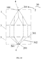
- the solution that the support part 3 does not overlap with the filtering part 1 in the axial direction is described.
- a part or all of the length of the support part 3 overlaps with the filtering part 1" in the axial direction of the filter device 20.
- the first end of the support part 3 is connected to both the second end of the filtering part 1" and the said one end of the retrieving part 5 when a part or all of the length of the support part 3 overlaps with the filtering part 1" in the axial direction of the filter device 20.
- the first end of the filtering part 1" is located at 1/2 of the height of the support part 3, and the second end of the filtering part 1" is not lower than the height of the edge (i.e., the lower edge from the perspective of FIG. 8 ) of the first end of the support part 3.
- the height of the support part 3 refers to a maximum linear distance between the edge (i.e., the junction with the retrieving part 5) of the first end of the support part 3 fixed to the filtering part 1" and the edge (i.e., the upper edge from the perspective of FIG. 8 , i.e., one end close to the heart) of the second end of the support part 3 in the axial direction of the filter device 20.
- the second end of the filtering part 1" refers to the end away from the heart after being fixed to the support part 3.
- the support part 3 overlaps with the filtering part 1" in the axial direction, which can increase the support strength of the filtering part 1", and the structure is better.
- the second end of the filtering part 1" is connected to the edge of the first end of the support part 3, and meanwhile, the retrieving part 5 is also connected to the edge of the first end of the support part 3.
- the first end of the filtering part 1" is also connected to the support part 3.
- the edge of the second end of the support part 3 is close to the heart.
- FIG. 9 is a schematic structural diagram of the partially degraded filter device 20 of FIG. 8 .
- the structural bodies of the filtering part 1" rebound and fits with the vascular wall to be converted into a tubular stent structure and thus does not have a filtering function any more.
- the filter device provided in this embodiment is basically the same as that in Embodiment 2, and the following description is provided only for describing differences.
- FIG. 10 is a schematic structural diagram of a filter device according to Embodiment 3 of the present invention.
- the filter device 30 includes a filtering part 1, a constraining part 2, a support part 3, a connecting part 4, and a retrieving part 5.
- Two connecting parts 4 are provided, one is disposed at the head end of the filter device 30, and the other is disposed at the tail end of the filter device 30.
- the filter device 30 can be retrieved through the connecting part 4 located at the head end of the filter device 30, and the filter device 20 can also be retrieved through another connecting part 4 located at the tail end of the filter device 30.
- the connecting part 4 and the head/tail end of the filter device 30 in this embodiment reference can be made to Embodiments 1 and 2. Details are not described herein again.
- the filter device 30 can be retrieved through the jugular vein pathway, and can also be retrieved through the femoral vein pathway.
- the support part 3 provided in Embodiment 3 can also be folded upwards.
- the second end of the stent part, i.e., the said other end of the retrieving part always forms the tail end of the filter device when the support part 3 is folded upward.
- the foregoing embodiments describe in detail how the constraining part constrains the filtering part and the retrieving part.
- the present invention includes, but is not limited to, the constraining modes listed in the foregoing embodiments, and any transformations made based on the constraining modes provided by the foregoing embodiments fall within the protection scope of the present invention. Those skilled in the art can draw inferences about other cases from one instance according to the contents of the foregoing embodiments.
- the filter device provided by the present invention can be taken out from the human body or can be converted into a tubular stent in the case that the patient does not require the protection from the filter device, so as to reduce the incidence rate of long-term complications such as vena cava blockage and perforation.
- the filter device provided by the present invention makes it possible to avoid the secondary surgery, and the filter device is able to be converted into a tubular stent even if the filter device cannot be taken out beyond the preset time window or due to other reasons, thereby reducing the incidence rate of various complications caused by long-term stay of the filter device.
Landscapes
- Health & Medical Sciences (AREA)
- Engineering & Computer Science (AREA)
- Biomedical Technology (AREA)
- Life Sciences & Earth Sciences (AREA)
- General Health & Medical Sciences (AREA)
- Oral & Maxillofacial Surgery (AREA)
- Heart & Thoracic Surgery (AREA)
- Vascular Medicine (AREA)
- Cardiology (AREA)
- Animal Behavior & Ethology (AREA)
- Transplantation (AREA)
- Public Health (AREA)
- Veterinary Medicine (AREA)
- Gastroenterology & Hepatology (AREA)
- Pulmonology (AREA)
- Surgical Instruments (AREA)
- Prostheses (AREA)
Applications Claiming Priority (2)
| Application Number | Priority Date | Filing Date | Title |
|---|---|---|---|
| CN201710714197.9A CN109394379B (zh) | 2017-08-18 | 2017-08-18 | 滤器装置 |
| PCT/CN2018/099490 WO2019033977A1 (fr) | 2017-08-18 | 2018-08-09 | Dispositif de filtre |
Publications (3)
| Publication Number | Publication Date |
|---|---|
| EP3669823A1 true EP3669823A1 (fr) | 2020-06-24 |
| EP3669823A4 EP3669823A4 (fr) | 2020-07-08 |
| EP3669823B1 EP3669823B1 (fr) | 2022-11-23 |
Family
ID=65361922
Family Applications (1)
| Application Number | Title | Priority Date | Filing Date |
|---|---|---|---|
| EP18846869.8A Active EP3669823B1 (fr) | 2017-08-18 | 2018-08-09 | Dispositif de filtre |
Country Status (4)
| Country | Link |
|---|---|
| US (1) | US11779450B2 (fr) |
| EP (1) | EP3669823B1 (fr) |
| CN (1) | CN109394379B (fr) |
| WO (1) | WO2019033977A1 (fr) |
Families Citing this family (6)
| Publication number | Priority date | Publication date | Assignee | Title |
|---|---|---|---|---|
| EP3968898A4 (fr) * | 2019-05-17 | 2023-07-19 | VeoSource SA | Filtre de sang aortique autonettoyant |
| CN113017908B (zh) * | 2019-12-25 | 2023-06-16 | 先健科技(深圳)有限公司 | 滤器及滤器系统 |
| CN111388140B (zh) * | 2020-02-25 | 2025-02-14 | 甘肃省人民医院 | 一种静脉滤器 |
| CN113633431A (zh) * | 2020-05-11 | 2021-11-12 | 上海蓝脉医疗科技有限公司 | 滤器 |
| CN116407319A (zh) * | 2021-12-30 | 2023-07-11 | 先健科技(深圳)有限公司 | 滤器系统 |
| CN116407320A (zh) * | 2021-12-30 | 2023-07-11 | 先健科技(深圳)有限公司 | 滤器及滤器系统 |
Family Cites Families (31)
| Publication number | Priority date | Publication date | Assignee | Title |
|---|---|---|---|---|
| EP1582178B1 (fr) | 1999-02-01 | 2012-09-26 | Board Of Regents, The University Of Texas System | Dispositifs intravasculaires tissés et procédés de fabrication desdits dispositifs |
| AU2001241603A1 (en) * | 2000-02-23 | 2001-09-03 | Boston Scientific Limited | Intravascular filtering devices and methods |
| CA2630536A1 (fr) * | 2005-12-07 | 2007-06-14 | C.R. Bard, Inc. | Filtre pour veine cave avec stent |
| KR101377117B1 (ko) * | 2006-07-19 | 2014-03-21 | 노베이트 메디칼 리미티드 | 혈관 필터 |
| US20100183230A1 (en) | 2007-06-27 | 2010-07-22 | Nec Corporation | Feature attribute calculation apparatus, feature extraction apparatus, pattern matching apparatus, and method |
| US20100016881A1 (en) * | 2008-07-16 | 2010-01-21 | Cook Incorporated | Biodegradable filter |
| US8025675B2 (en) * | 2008-08-14 | 2011-09-27 | Cook Medical Technologies Llc | Temporary filter device |
| EP2381892B1 (fr) * | 2009-01-16 | 2020-09-09 | Novate Medical Limited | Système de filtre vasculaire |
| CN102355871B (zh) * | 2009-01-16 | 2014-07-09 | 诺瓦特医疗有限公司 | 脉管过滤器装置 |
| WO2010082187A1 (fr) * | 2009-01-16 | 2010-07-22 | Novate Medical Limited | Dispositif de filtre vasculaire |
| WO2011079285A1 (fr) * | 2009-12-23 | 2011-06-30 | Pavilion Medical Innovations | Dispositifs de filtre vasculaire réversible et procédés d'utilisation de ceux-ci |
| WO2012071224A1 (fr) * | 2010-11-24 | 2012-05-31 | Cook Medical Technologies Llc | Filtre vasculaire en forme de dôme |
| WO2012118696A1 (fr) | 2011-02-28 | 2012-09-07 | Crossroad Labs | Filtre vasculaire absorbable |
| US20120277787A1 (en) * | 2011-04-28 | 2012-11-01 | Mitchell Donn Eggers | Vascular Filter Stent |
| US9011479B2 (en) * | 2011-12-16 | 2015-04-21 | Cleve Koehler | Vena cava filter with bidirectional retrieval |
| CN102824229A (zh) | 2012-09-20 | 2012-12-19 | 上海市第六人民医院 | 一种免取出的临时型腔静脉滤器及其制作方法 |
| US10076398B2 (en) * | 2012-12-27 | 2018-09-18 | Cook Medical Technologies Llc | Biodegradable filter |
| JP2016509909A (ja) * | 2013-03-15 | 2016-04-04 | ノベート・メディカル・リミテッド | 血管フィルタデバイス |
| CN104434339A (zh) * | 2013-09-25 | 2015-03-25 | 傅强 | 腔静脉滤器 |
| CN203468794U (zh) * | 2013-09-25 | 2014-03-12 | 傅强 | 局部可降解的腔静脉滤器 |
| GB2531587A (en) * | 2014-10-23 | 2016-04-27 | Cook Medical Technologies Llc | Implantable medical device exhibiting diminishing radial force |
| GB2536439C (en) * | 2015-03-16 | 2019-10-16 | Cook Medical Technologies Llc | Medical device assembly with constriction mechanism |
| CN106491238B (zh) * | 2015-09-07 | 2020-06-16 | 上海微创心脉医疗科技股份有限公司 | 滤器装置 |
| CN106491239B (zh) * | 2015-09-08 | 2018-12-11 | 微创心脉医疗科技(上海)有限公司 | 滤器装置 |
| CN105213065B (zh) * | 2015-10-15 | 2019-12-13 | 先健科技(深圳)有限公司 | 滤器 |
| CN106806037B (zh) * | 2015-11-30 | 2019-05-31 | 先健科技(深圳)有限公司 | 滤器 |
| CN106913392B (zh) * | 2015-12-28 | 2019-05-31 | 先健科技(深圳)有限公司 | 滤器 |
| CN107174373B (zh) * | 2016-03-09 | 2019-03-12 | 微创心脉医疗科技(上海)有限公司 | 滤器装置 |
| CN206342563U (zh) | 2016-08-18 | 2017-07-21 | 苏州万斯医疗科技有限公司 | 一种自膨式滤器支架 |
| CN106937892B (zh) * | 2017-05-12 | 2019-02-19 | 谷涌泉 | 一种长置型腔静脉滤器 |
| CN208910577U (zh) * | 2017-08-18 | 2019-05-31 | 上海微创心脉医疗科技股份有限公司 | 滤器装置 |
-
2017
- 2017-08-18 CN CN201710714197.9A patent/CN109394379B/zh active Active
-
2018
- 2018-08-09 WO PCT/CN2018/099490 patent/WO2019033977A1/fr not_active Ceased
- 2018-08-09 US US16/627,592 patent/US11779450B2/en active Active
- 2018-08-09 EP EP18846869.8A patent/EP3669823B1/fr active Active
Also Published As
| Publication number | Publication date |
|---|---|
| EP3669823A4 (fr) | 2020-07-08 |
| US20200129281A1 (en) | 2020-04-30 |
| WO2019033977A1 (fr) | 2019-02-21 |
| CN109394379B (zh) | 2024-09-20 |
| US11779450B2 (en) | 2023-10-10 |
| CN109394379A (zh) | 2019-03-01 |
| EP3669823B1 (fr) | 2022-11-23 |
Similar Documents
| Publication | Publication Date | Title |
|---|---|---|
| US11779450B2 (en) | Filter device | |
| KR102044599B1 (ko) | 공간 충진 장치 | |
| EP2895108B1 (fr) | Ancre de fixation pour dispositif d'occlusion | |
| US9271818B2 (en) | Conical vena cava filter with jugular or femoral retrieval | |
| US9107733B2 (en) | Removable blood conduit filter | |
| US9011479B2 (en) | Vena cava filter with bidirectional retrieval | |
| US8864793B2 (en) | Vein filter | |
| US7794472B2 (en) | Single wire intravascular filter | |
| US20150112379A1 (en) | Vein filter | |
| CA2711813A1 (fr) | Filtre veineux | |
| US20240108450A1 (en) | Peripheral vascular filtration systems and methods | |
| WO2022237836A1 (fr) | Dispositif de protection embolique | |
| EP4059452B1 (fr) | Dispositif d'extraction d'obstruction vasculaire doté d'un mécanisme de pincement des cages coulissantes | |
| EP2768427B1 (fr) | Filtre-cave pouvant être récupéré par la veine fémorale | |
| CN205758765U (zh) | 一种编织型腔静脉滤器 | |
| CN113017908A (zh) | 滤器及滤器系统 |
Legal Events
| Date | Code | Title | Description |
|---|---|---|---|
| STAA | Information on the status of an ep patent application or granted ep patent |
Free format text: STATUS: THE INTERNATIONAL PUBLICATION HAS BEEN MADE |
|
| PUAI | Public reference made under article 153(3) epc to a published international application that has entered the european phase |
Free format text: ORIGINAL CODE: 0009012 |
|
| STAA | Information on the status of an ep patent application or granted ep patent |
Free format text: STATUS: REQUEST FOR EXAMINATION WAS MADE |
|
| 17P | Request for examination filed |
Effective date: 20191227 |
|
| AK | Designated contracting states |
Kind code of ref document: A1 Designated state(s): AL AT BE BG CH CY CZ DE DK EE ES FI FR GB GR HR HU IE IS IT LI LT LU LV MC MK MT NL NO PL PT RO RS SE SI SK SM TR |
|
| AX | Request for extension of the european patent |
Extension state: BA ME |
|
| A4 | Supplementary search report drawn up and despatched |
Effective date: 20200605 |
|
| RIC1 | Information provided on ipc code assigned before grant |
Ipc: A61F 2/01 20060101AFI20200529BHEP Ipc: A61F 2/95 20130101ALN20200529BHEP Ipc: A61F 2/86 20130101ALN20200529BHEP |
|
| DAV | Request for validation of the european patent (deleted) | ||
| DAX | Request for extension of the european patent (deleted) | ||
| RAP1 | Party data changed (applicant data changed or rights of an application transferred) |
Owner name: SHANGHAI BLUEVASCULAR MEDTECH CO., LTD. |
|
| GRAP | Despatch of communication of intention to grant a patent |
Free format text: ORIGINAL CODE: EPIDOSNIGR1 |
|
| STAA | Information on the status of an ep patent application or granted ep patent |
Free format text: STATUS: GRANT OF PATENT IS INTENDED |
|
| RIC1 | Information provided on ipc code assigned before grant |
Ipc: A61F 2/86 20130101ALN20220705BHEP Ipc: A61F 2/95 20130101ALN20220705BHEP Ipc: A61F 2/01 20060101AFI20220705BHEP |
|
| RIC1 | Information provided on ipc code assigned before grant |
Ipc: A61F 2/86 20130101ALN20220712BHEP Ipc: A61F 2/95 20130101ALN20220712BHEP Ipc: A61F 2/01 20060101AFI20220712BHEP |
|
| INTG | Intention to grant announced |
Effective date: 20220726 |
|
| GRAS | Grant fee paid |
Free format text: ORIGINAL CODE: EPIDOSNIGR3 |
|
| GRAA | (expected) grant |
Free format text: ORIGINAL CODE: 0009210 |
|
| STAA | Information on the status of an ep patent application or granted ep patent |
Free format text: STATUS: THE PATENT HAS BEEN GRANTED |
|
| AK | Designated contracting states |
Kind code of ref document: B1 Designated state(s): AL AT BE BG CH CY CZ DE DK EE ES FI FR GB GR HR HU IE IS IT LI LT LU LV MC MK MT NL NO PL PT RO RS SE SI SK SM TR |
|
| REG | Reference to a national code |
Ref country code: GB Ref legal event code: FG4D |
|
| REG | Reference to a national code |
Ref country code: CH Ref legal event code: EP |
|
| REG | Reference to a national code |
Ref country code: AT Ref legal event code: REF Ref document number: 1532688 Country of ref document: AT Kind code of ref document: T Effective date: 20221215 Ref country code: DE Ref legal event code: R096 Ref document number: 602018043468 Country of ref document: DE |
|
| REG | Reference to a national code |
Ref country code: IE Ref legal event code: FG4D |
|
| REG | Reference to a national code |
Ref country code: LT Ref legal event code: MG9D |
|
| REG | Reference to a national code |
Ref country code: NL Ref legal event code: MP Effective date: 20221123 |
|
| REG | Reference to a national code |
Ref country code: AT Ref legal event code: MK05 Ref document number: 1532688 Country of ref document: AT Kind code of ref document: T Effective date: 20221123 |
|
| PG25 | Lapsed in a contracting state [announced via postgrant information from national office to epo] |
Ref country code: SE Free format text: LAPSE BECAUSE OF FAILURE TO SUBMIT A TRANSLATION OF THE DESCRIPTION OR TO PAY THE FEE WITHIN THE PRESCRIBED TIME-LIMIT Effective date: 20221123 Ref country code: PT Free format text: LAPSE BECAUSE OF FAILURE TO SUBMIT A TRANSLATION OF THE DESCRIPTION OR TO PAY THE FEE WITHIN THE PRESCRIBED TIME-LIMIT Effective date: 20230323 Ref country code: NO Free format text: LAPSE BECAUSE OF FAILURE TO SUBMIT A TRANSLATION OF THE DESCRIPTION OR TO PAY THE FEE WITHIN THE PRESCRIBED TIME-LIMIT Effective date: 20230223 Ref country code: LT Free format text: LAPSE BECAUSE OF FAILURE TO SUBMIT A TRANSLATION OF THE DESCRIPTION OR TO PAY THE FEE WITHIN THE PRESCRIBED TIME-LIMIT Effective date: 20221123 Ref country code: FI Free format text: LAPSE BECAUSE OF FAILURE TO SUBMIT A TRANSLATION OF THE DESCRIPTION OR TO PAY THE FEE WITHIN THE PRESCRIBED TIME-LIMIT Effective date: 20221123 Ref country code: ES Free format text: LAPSE BECAUSE OF FAILURE TO SUBMIT A TRANSLATION OF THE DESCRIPTION OR TO PAY THE FEE WITHIN THE PRESCRIBED TIME-LIMIT Effective date: 20221123 Ref country code: AT Free format text: LAPSE BECAUSE OF FAILURE TO SUBMIT A TRANSLATION OF THE DESCRIPTION OR TO PAY THE FEE WITHIN THE PRESCRIBED TIME-LIMIT Effective date: 20221123 |
|
| PG25 | Lapsed in a contracting state [announced via postgrant information from national office to epo] |
Ref country code: RS Free format text: LAPSE BECAUSE OF FAILURE TO SUBMIT A TRANSLATION OF THE DESCRIPTION OR TO PAY THE FEE WITHIN THE PRESCRIBED TIME-LIMIT Effective date: 20221123 Ref country code: PL Free format text: LAPSE BECAUSE OF FAILURE TO SUBMIT A TRANSLATION OF THE DESCRIPTION OR TO PAY THE FEE WITHIN THE PRESCRIBED TIME-LIMIT Effective date: 20221123 Ref country code: LV Free format text: LAPSE BECAUSE OF FAILURE TO SUBMIT A TRANSLATION OF THE DESCRIPTION OR TO PAY THE FEE WITHIN THE PRESCRIBED TIME-LIMIT Effective date: 20221123 Ref country code: IS Free format text: LAPSE BECAUSE OF FAILURE TO SUBMIT A TRANSLATION OF THE DESCRIPTION OR TO PAY THE FEE WITHIN THE PRESCRIBED TIME-LIMIT Effective date: 20230323 Ref country code: HR Free format text: LAPSE BECAUSE OF FAILURE TO SUBMIT A TRANSLATION OF THE DESCRIPTION OR TO PAY THE FEE WITHIN THE PRESCRIBED TIME-LIMIT Effective date: 20221123 Ref country code: GR Free format text: LAPSE BECAUSE OF FAILURE TO SUBMIT A TRANSLATION OF THE DESCRIPTION OR TO PAY THE FEE WITHIN THE PRESCRIBED TIME-LIMIT Effective date: 20230224 |
|
| PG25 | Lapsed in a contracting state [announced via postgrant information from national office to epo] |
Ref country code: NL Free format text: LAPSE BECAUSE OF FAILURE TO SUBMIT A TRANSLATION OF THE DESCRIPTION OR TO PAY THE FEE WITHIN THE PRESCRIBED TIME-LIMIT Effective date: 20221123 |
|
| PG25 | Lapsed in a contracting state [announced via postgrant information from national office to epo] |
Ref country code: SM Free format text: LAPSE BECAUSE OF FAILURE TO SUBMIT A TRANSLATION OF THE DESCRIPTION OR TO PAY THE FEE WITHIN THE PRESCRIBED TIME-LIMIT Effective date: 20221123 Ref country code: RO Free format text: LAPSE BECAUSE OF FAILURE TO SUBMIT A TRANSLATION OF THE DESCRIPTION OR TO PAY THE FEE WITHIN THE PRESCRIBED TIME-LIMIT Effective date: 20221123 Ref country code: EE Free format text: LAPSE BECAUSE OF FAILURE TO SUBMIT A TRANSLATION OF THE DESCRIPTION OR TO PAY THE FEE WITHIN THE PRESCRIBED TIME-LIMIT Effective date: 20221123 Ref country code: DK Free format text: LAPSE BECAUSE OF FAILURE TO SUBMIT A TRANSLATION OF THE DESCRIPTION OR TO PAY THE FEE WITHIN THE PRESCRIBED TIME-LIMIT Effective date: 20221123 Ref country code: CZ Free format text: LAPSE BECAUSE OF FAILURE TO SUBMIT A TRANSLATION OF THE DESCRIPTION OR TO PAY THE FEE WITHIN THE PRESCRIBED TIME-LIMIT Effective date: 20221123 |
|
| REG | Reference to a national code |
Ref country code: DE Ref legal event code: R097 Ref document number: 602018043468 Country of ref document: DE |
|
| PG25 | Lapsed in a contracting state [announced via postgrant information from national office to epo] |
Ref country code: SK Free format text: LAPSE BECAUSE OF FAILURE TO SUBMIT A TRANSLATION OF THE DESCRIPTION OR TO PAY THE FEE WITHIN THE PRESCRIBED TIME-LIMIT Effective date: 20221123 Ref country code: AL Free format text: LAPSE BECAUSE OF FAILURE TO SUBMIT A TRANSLATION OF THE DESCRIPTION OR TO PAY THE FEE WITHIN THE PRESCRIBED TIME-LIMIT Effective date: 20221123 |
|
| PLBE | No opposition filed within time limit |
Free format text: ORIGINAL CODE: 0009261 |
|
| STAA | Information on the status of an ep patent application or granted ep patent |
Free format text: STATUS: NO OPPOSITION FILED WITHIN TIME LIMIT |
|
| 26N | No opposition filed |
Effective date: 20230824 |
|
| PG25 | Lapsed in a contracting state [announced via postgrant information from national office to epo] |
Ref country code: SI Free format text: LAPSE BECAUSE OF FAILURE TO SUBMIT A TRANSLATION OF THE DESCRIPTION OR TO PAY THE FEE WITHIN THE PRESCRIBED TIME-LIMIT Effective date: 20221123 |
|
| PGFP | Annual fee paid to national office [announced via postgrant information from national office to epo] |
Ref country code: DE Payment date: 20230821 Year of fee payment: 6 |
|
| P01 | Opt-out of the competence of the unified patent court (upc) registered |
Effective date: 20231128 |
|
| PG25 | Lapsed in a contracting state [announced via postgrant information from national office to epo] |
Ref country code: MC Free format text: LAPSE BECAUSE OF FAILURE TO SUBMIT A TRANSLATION OF THE DESCRIPTION OR TO PAY THE FEE WITHIN THE PRESCRIBED TIME-LIMIT Effective date: 20221123 |
|
| REG | Reference to a national code |
Ref country code: CH Ref legal event code: PL |
|
| PG25 | Lapsed in a contracting state [announced via postgrant information from national office to epo] |
Ref country code: MC Free format text: LAPSE BECAUSE OF FAILURE TO SUBMIT A TRANSLATION OF THE DESCRIPTION OR TO PAY THE FEE WITHIN THE PRESCRIBED TIME-LIMIT Effective date: 20221123 |
|
| PG25 | Lapsed in a contracting state [announced via postgrant information from national office to epo] |
Ref country code: LU Free format text: LAPSE BECAUSE OF NON-PAYMENT OF DUE FEES Effective date: 20230809 |
|
| GBPC | Gb: european patent ceased through non-payment of renewal fee |
Effective date: 20230809 |
|
| PG25 | Lapsed in a contracting state [announced via postgrant information from national office to epo] |
Ref country code: LU Free format text: LAPSE BECAUSE OF NON-PAYMENT OF DUE FEES Effective date: 20230809 Ref country code: CH Free format text: LAPSE BECAUSE OF NON-PAYMENT OF DUE FEES Effective date: 20230831 |
|
| REG | Reference to a national code |
Ref country code: BE Ref legal event code: MM Effective date: 20230831 |
|
| REG | Reference to a national code |
Ref country code: IE Ref legal event code: MM4A |
|
| PG25 | Lapsed in a contracting state [announced via postgrant information from national office to epo] |
Ref country code: IT Free format text: LAPSE BECAUSE OF FAILURE TO SUBMIT A TRANSLATION OF THE DESCRIPTION OR TO PAY THE FEE WITHIN THE PRESCRIBED TIME-LIMIT Effective date: 20221123 |
|
| PG25 | Lapsed in a contracting state [announced via postgrant information from national office to epo] |
Ref country code: IE Free format text: LAPSE BECAUSE OF NON-PAYMENT OF DUE FEES Effective date: 20230809 |
|
| PG25 | Lapsed in a contracting state [announced via postgrant information from national office to epo] |
Ref country code: GB Free format text: LAPSE BECAUSE OF NON-PAYMENT OF DUE FEES Effective date: 20230809 |
|
| PG25 | Lapsed in a contracting state [announced via postgrant information from national office to epo] |
Ref country code: IE Free format text: LAPSE BECAUSE OF NON-PAYMENT OF DUE FEES Effective date: 20230809 Ref country code: GB Free format text: LAPSE BECAUSE OF NON-PAYMENT OF DUE FEES Effective date: 20230809 Ref country code: FR Free format text: LAPSE BECAUSE OF NON-PAYMENT OF DUE FEES Effective date: 20230831 |
|
| PG25 | Lapsed in a contracting state [announced via postgrant information from national office to epo] |
Ref country code: BE Free format text: LAPSE BECAUSE OF NON-PAYMENT OF DUE FEES Effective date: 20230831 |
|
| PG25 | Lapsed in a contracting state [announced via postgrant information from national office to epo] |
Ref country code: BG Free format text: LAPSE BECAUSE OF FAILURE TO SUBMIT A TRANSLATION OF THE DESCRIPTION OR TO PAY THE FEE WITHIN THE PRESCRIBED TIME-LIMIT Effective date: 20221123 |
|
| PG25 | Lapsed in a contracting state [announced via postgrant information from national office to epo] |
Ref country code: BG Free format text: LAPSE BECAUSE OF FAILURE TO SUBMIT A TRANSLATION OF THE DESCRIPTION OR TO PAY THE FEE WITHIN THE PRESCRIBED TIME-LIMIT Effective date: 20221123 |
|
| REG | Reference to a national code |
Ref country code: DE Ref legal event code: R119 Ref document number: 602018043468 Country of ref document: DE |
|
| PG25 | Lapsed in a contracting state [announced via postgrant information from national office to epo] |
Ref country code: DE Free format text: LAPSE BECAUSE OF NON-PAYMENT OF DUE FEES Effective date: 20250301 |
|
| PG25 | Lapsed in a contracting state [announced via postgrant information from national office to epo] |
Ref country code: CY Free format text: LAPSE BECAUSE OF FAILURE TO SUBMIT A TRANSLATION OF THE DESCRIPTION OR TO PAY THE FEE WITHIN THE PRESCRIBED TIME-LIMIT; INVALID AB INITIO Effective date: 20180809 |
|
| PG25 | Lapsed in a contracting state [announced via postgrant information from national office to epo] |
Ref country code: HU Free format text: LAPSE BECAUSE OF FAILURE TO SUBMIT A TRANSLATION OF THE DESCRIPTION OR TO PAY THE FEE WITHIN THE PRESCRIBED TIME-LIMIT; INVALID AB INITIO Effective date: 20180809 |
|
| PG25 | Lapsed in a contracting state [announced via postgrant information from national office to epo] |
Ref country code: TR Free format text: LAPSE BECAUSE OF FAILURE TO SUBMIT A TRANSLATION OF THE DESCRIPTION OR TO PAY THE FEE WITHIN THE PRESCRIBED TIME-LIMIT Effective date: 20221123 |