EP3669832A2 - Orthèse de cheville - Google Patents
Orthèse de cheville Download PDFInfo
- Publication number
- EP3669832A2 EP3669832A2 EP19208452.3A EP19208452A EP3669832A2 EP 3669832 A2 EP3669832 A2 EP 3669832A2 EP 19208452 A EP19208452 A EP 19208452A EP 3669832 A2 EP3669832 A2 EP 3669832A2
- Authority
- EP
- European Patent Office
- Prior art keywords
- orthosis
- medial
- ankle
- rail
- rail element
- Prior art date
- Legal status (The legal status is an assumption and is not a legal conclusion. Google has not performed a legal analysis and makes no representation as to the accuracy of the status listed.)
- Granted
Links
Images



Classifications
-
- A—HUMAN NECESSITIES
- A61—MEDICAL OR VETERINARY SCIENCE; HYGIENE
- A61F—FILTERS IMPLANTABLE INTO BLOOD VESSELS; PROSTHESES; DEVICES PROVIDING PATENCY TO, OR PREVENTING COLLAPSING OF, TUBULAR STRUCTURES OF THE BODY, e.g. STENTS; ORTHOPAEDIC, NURSING OR CONTRACEPTIVE DEVICES; FOMENTATION; TREATMENT OR PROTECTION OF EYES OR EARS; BANDAGES, DRESSINGS OR ABSORBENT PADS; FIRST-AID KITS
- A61F5/00—Orthopaedic methods or devices for non-surgical treatment of bones or joints; Nursing devices ; Anti-rape devices
- A61F5/01—Orthopaedic devices, e.g. long-term immobilising or pressure directing devices for treating broken or deformed bones such as splints, casts or braces
- A61F5/0102—Orthopaedic devices, e.g. long-term immobilising or pressure directing devices for treating broken or deformed bones such as splints, casts or braces specially adapted for correcting deformities of the limbs or for supporting them; Ortheses, e.g. with articulations
- A61F5/0104—Orthopaedic devices, e.g. long-term immobilising or pressure directing devices for treating broken or deformed bones such as splints, casts or braces specially adapted for correcting deformities of the limbs or for supporting them; Ortheses, e.g. with articulations without articulation
- A61F5/0111—Orthopaedic devices, e.g. long-term immobilising or pressure directing devices for treating broken or deformed bones such as splints, casts or braces specially adapted for correcting deformities of the limbs or for supporting them; Ortheses, e.g. with articulations without articulation for the feet or ankles
Definitions
- the present invention relates to an ankle orthosis according to the preamble of claim 1 and claim 6.
- the ankle orthoses according to the invention can, in accordance with the preamble of claim 1, a, in particular resilient, flexurally rigid medial splint element, which in the applied state on the foot - And inner leg is arranged, and comprise a, in particular resilient, flexurally rigid lateral rail element, which is arranged on the outer side of the foot and lower leg in the applied state.
- the rail elements are formed separately from one another and in the applied state spaced from each other.
- the ankle orthoses further comprise a tensioning system which is designed and arranged to close the orthosis around the ankle and to apply it tightly.
- the tensioning system in turn comprises several belts.
- a rear belt is designed and arranged to connect the rail elements in the area of the calf.
- This belt also serves to form a rear abutment section for the calf. It therefore forms a section against which the calf can rest when the orthosis is stretched around the foot.
- there may be padding between the calf and the belt for example a base body of the orthosis, as will be explained in detail later.
- the tensioning system also has at least one front belt for connecting the rail elements in the area of the lower leg front. This belt forms the counterpart to the rear belt on the front of the orthosis.
- the tensioning system also has at least one lower belt for connecting the rail elements in the area of the sole of the foot.
- the ankle orthoses according to the invention can, however, also comprise a boot-like basic body that is designed to be flexible, according to the preamble of claim 6.
- this base body is open towards the front.
- the base body or the orthosis can be pushed onto the foot from the heel in the longitudinal direction of the foot.
- the base body is made of a flexible textile material.
- a lower end of the base body is formed by a lower sole section.
- the sole section can be made elastic in the area of the sole of the foot.
- the sole section can thus adjust to the individual foot width.
- An additional, non-elastic connecting element can also be present in the area of the sole section.
- This connecting element is preferably parallel to the above-mentioned elastic sole section, can be designed in two parts, and serves to connect the medial and the lateral section of the base body in an adjustable, non-elastic manner.
- the connection can be made, for example, by a Velcro-Velcro connection.
- the base body Above the rear end of the sole section, the base body has a rear contact section for the calf of the wearer of the orthosis.
- the orthosis has a tensioning system.
- the tensioning system is designed and arranged for the orthosis, in particular essentially steplessly, in order to close the ankle and apply it tightly to it.
- the orthosis also has a medial rail element and a lateral rail element.
- the medial rail element is rigid and in particular resiliently elastic. In the applied state, the medial rail element is arranged on the inside of the foot and lower leg.
- the lateral rail element is also rigid and, in particular, resiliently elastic and is arranged on the outside of the foot or lower leg in the applied state.
- the two are Rail elements, that is to say the medial and the lateral rail element, are formed separately from one another and spaced apart from one another in the applied state.
- Such orthoses serve to stabilize the ankle.
- the ankle or the ligaments can be relieved in the event of an ankle already damaged, for example in the event of a ligament injury, and a further worsening of the injury can be prevented.
- wearing such an orthosis can also prevent injury to the ankle and the connected ligament apparatus.
- the supportive effect of the ankle is often insufficient.
- the aim of the present invention is therefore to provide an ankle orthosis that stabilizes the ankle sufficiently, yet is comfortable to wear and allows a certain mobility of the ankle.
- This object is achieved by an ankle orthosis with the features of claim 1 and alternatively by an ankle orthosis with the features of claim 2 or 6 or 7.
- the ankle orthosis according to the invention is designed according to the preamble of claim 1 or 6 and is characterized according to a variant in that the medial splint element, viewed in the distal direction, extends from the height of the tibial bone at least to the middle, in particular to the lower (distal) third, in particular to the lower sixth, of the calcaneus and with its lower end, which is arranged below the ankle, extends backwards into the rear third, in particular the rear quarter, in particular the rear sixth , of the heel bone, in particular in the area of the heel bone, extends.
- the medial splint element viewed in the distal direction, extends from the height of the tibial bone at least to the middle, in particular to the lower (distal) third, in particular to the lower sixth, of the calcaneus and with its lower end, which is arranged below the ankle, extends backwards into the rear third, in particular the rear quarter, in particular the rear sixth , of the heel bone, in
- the medial splint element can also extend backwards (with its distal area or the area located below the center of the heel bone) to the position of the contact section for the calf. It is thereby achieved that the medial splint element on the calf on the one hand can take a firm contact with the shin opposite the shin bone and on the other hand extends so far down that it can stabilize the heel bone and over the heel bone the ankle joint.
- the medial splint element extends so far back that it protrudes into the area of the heel bone (with its distal area or the area located below the center of the heel bone) so that it has a direct stabilizing contact surface with the heel bone. As a result, the ankle can advantageously be stabilized.
- the medial splint element does not extend so far to the rear, but extends downwards in a continuous, or even tapering, width, coming from the shin bone in the lower region, so to speak, without extension.
- the orthosis according to the invention has a medial splint element which, as seen from the inside of the foot, overlaps with the heel bump so that it can exert force directly on it and thereby stabilize the ankle.
- the medial splint element lies more in the area of the sole of the foot or in the area of the longitudinal arch of the foot or the tarsal bone or the front area of the heel bone.
- the rail element has little bony contact surface, so that a force transmission, in particular counteracting excessive supination, and a stabilizing effect or force transmission are only possible to a minor extent.
- an ankle orthosis according to the preamble of claim 1, which is characterized in that the medial splint element extends in its lower, i.e. distal third, essentially as far back as in the part of the splint element above it (e.g. However, a fastening eyelet made of the material of the rail element can protrude slightly to the rear, but the rearmost part of the part of the rail element that supports or is supported on the lower leg lies in the lower area or distal third).
- the medial rail element extends further forward than in the part of the rail element lying above it.
- the rear edge of the medial splint element can run essentially in a straight line.
- the medial rail element can have a forward-facing extension in its lower third.
- the extension can form the most forwardly extending part of the medial splint element. in particular, the medial splint element initially having a protruding region along its front edge, followed by a recessed region in the distal direction, followed by the extension.
- an ankle orthosis according to the preamble of claim 6, which is characterized in that the medial splint element, viewed in the distal direction, extends from the proximal half, in particular the proximal third, in particular the proximal quarter, of the orthosis extends at least to the distal sixth, in particular to the distal eighth, in particular essentially to the distal edge of the orthosis, i.e. essentially over the extent of the orthosis from top to bottom, i.e.
- the medial splint element of the orthosis is designed in such a way that it extends backwards — that is, dorsally — to the contact section of the base body for the calf.
- contact is also made with the heel bone or the heel bump, whereby the ankle joint can be advantageously stabilized.
- the tensioning system can comprise two rear straps arranged one above the other in the distal-proximal direction for connecting the rail elements in the area of the calf and for forming a rear contact section for the calf (ie they are tensioned against the calf in the applied state).
- the upper belt can engage the latter in the upper third of the medial rail element and / or the lateral rail element.
- the lower of the two rear belts can engage the middle third of the medial rail element and / or the lateral rail element.
- the tensioning system can have a front belt for connecting the rail elements in the area of the lower leg front.
- Belt can engage in the upper two thirds of the lateral rail element at two spaced apart locations.
- a connecting means for attaching a central portion of the belt to the medial rail element can be provided.
- the belt can thus at two points on the lateral rail element attack and be attached to the medial rail element in a simple manner via the connecting means.
- the connecting means is preferably designed such that the belt can be tensioned when fastened to the medial rail element.
- the tensioning system can include a front lower belt which engages on the lower third of the lateral rail element and has a connecting means for fastening the other end of the belt to the medial rail element.
- the medial rail element has a corresponding connection point for receiving the connecting means. This connection point can be arranged on the forward extension of the medial rail element.
- the medial rail element can have at its lower end an extension which extends forward in a longitudinal direction of the foot (ie in the longitudinal direction of the toes).
- the extension which extends towards the front, is designed and arranged in the applied state such that it extends into Longitudinal foot direction extends beyond the part of the base body which is arranged above the ankle in the applied state. If you look along the leg of the wearer in the distal direction, the part of the body that is located above the ankle ends in front of the extension along the longitudinal direction of the foot.
- the extension thus extends further to the toes of the wearer than the part of the base body which is arranged above the ankle.
- the forwardly extending extension may include a front end of the medial splint.
- the orthosis also provides support exactly where it is needed, namely on the heel bump on the one hand and on the other at the area of the tarsal to the metatarsal.
- the contact surface of the rail element in the region of the foot is enlarged, as a result of which the pressure required to stabilize the ankle is reduced and the ankle is thus advantageously supported.
- the medial splint element and the lateral splint element are connected to one another on the underside of the orthosis by means of a non-elastic connecting element that is flexible.
- a non-elastic connecting element that is flexible.
- This can be, for example, a flexible but inelastic belt or a band.
- the belt can be variable in length via a Velcro connection (hook and eye connection. The belt can be double guided for this purpose.)
- the rail elements can be moved relative to one another and the orthosis is in place simple way possible. In the applied state, however, the relative position of the two rail elements to one another is fixed and the rail elements can be tensioned against one another.
- the rail elements can both or one of the rail elements in each case be permanently connected to the base body. This can be achieved, for example, in that the rail elements are sewn to the base body. Other types of connection of the rail elements to the base body are also conceivable.
- the rail elements are preferably arranged on the outside of the base body, in particular in a non-detachable manner.
- the tensioning system is advantageously designed in such a way that it engages the medial rail element and / or the lateral rail element.
- the bracing of the orthosis can then be carried out by bracing the rail elements, so that the base body is predominantly placed on the foot by the rail elements and the tension is introduced via the rail elements themselves.
- the orthosis advantageously has at least one tension belt in the lower (distal) region of the rail elements and at least one tension belt in the upper (proximal) of the rail elements, that is to say in the region of the rail elements in the proximal-distal direction, at the level of the calf that surrounds it Area of the base body is arranged.
- the tension belt in the lower area of the rail elements can be on the extension of the attack medial splint element. In particular, it can be detachably connected to the medial rail element by means of a clip closure or a hook element.
- the tensioning belt which is arranged in the upper region, is advantageously designed as a pair of V-shaped tensioning belts with two belts which engage one of the rail elements at two different locations and are connected to one another at their other end and are advantageously connected to the other rail via a hooking system can.
- the orthosis preferably also has a belt which can be placed in a cross shape around the foot and calf. This belt is advantageously connected to the base body. This additional belt can be detachably connected to the base body, for example, via a Velcro connection or a hook and eye system.
- the base body is advantageously designed such that it has an opening for receiving the heel in the rear area between the sole section and the contact section of the base body.
- the opening for receiving the heel is preferably arranged and designed in such a way that the sole section extends quasi-horizontally and, in the vertical direction, the opening for receiving the heel follows the sole section directly and, as viewed in the proximal direction, therefore looks upwards towards the opening of the contact section of the body for the calf follows.
- a separate object of the present invention is to provide an ankle orthosis, which is designed in particular according to one of the previous embodiments, in which the bending stiffness of at least one rail element can be adjusted.
- an ankle orthosis which forms an independent invention, the ankle orthosis being designed in particular according to one of the previous embodiments, but not necessarily being designed according to one of the previous embodiments.
- a limp body and boot-like but open to the front is provided in this ankle orthosis.
- This base body is formed from a flexible textile material, as is also the case with the previously described embodiments.
- the base body also has the lower sole section with the rear abutment section of the base body for the calf arranged above its rear end.
- the base body can have the aspects of the invention described above and relating to the clamping system.
- the orthosis according to this independent invention also has a tensioning system which, as in the previous invention, is also arranged and designed to hold the orthosis, in particular in the Essentially stepless to close the ankle and put it tightly on it.
- the tensioning system may include the aspects of the invention described above that relate to the tensioning system.
- the orthosis also has at least one upgradeable, in particular resilient, flexurally rigid rail element.
- the orthosis according to this independent invention is characterized in that the orthosis comprises a particularly resilient, rigid insert element.
- the insert element can be combined with the previously mentioned upgradeable rail element. In combination with the rail element, this insert element can be connected to the rail element which can be upgraded in order to increase or increase its bending stiffness.
- connection points can be provided, which are arranged in particular in the upper and lower region of the rail element.
- the connection points can be designed in such a way that the inserted element is arranged in the connected state, extending in the distal direction parallel to the rail element, in particular lying flat against it.
- the insert element is connected to the rail element in the connected state via a form-fitting undercut or form-fit undercut at the respective connection points such that the area the connection points of the insertion element is prevented from moving relative to the rail element in the proximal-distal direction and / or in the longitudinal direction of the foot.
- This results in a stiffening of the upgradable rail element which goes beyond a mere addition of the bending stiffness of the insert element and the rail element.
- the connection of the two elements works synergistically in terms of their rigidity.
- the rail element which can be upgraded can in particular be the lateral rail element.
- the positive engagement is carried out on at least one of the connection points in such a way that a contact section is provided which is designed such that the insert element and the rail element are flat in at least three of the four quadrants of the plane spanned by the proximal-distal direction and the longitudinal direction of the foot rest against each other that the area of the connection points of the insert element is prevented from moving relative to the rail element in the proximal-distal direction and in the longitudinal direction of the foot.
- the insert element is preferably arranged medially from the rail element.
- the insert element can in particular be arranged between the base body and the rail element.
- the insert element can preferably be seen from above between the base body and the rail element be inserted.
- the base body and the rail element can be sewn together, in particular in the edge region of the rail element.
- there is also a lateral arrangement of the insertion element. the rail element conceivable.
- the form-fitting rear grip of at least one of the connection points has a further contact section which is designed in such a way that the insert element can move in the medial direction by means of a corresponding form-fitting rear grip (if the insertion element is medial from Rail element is arranged) or in the lateral direction (if the insertion element is arranged laterally from the rail element) with respect to the rail element.
- This positive engagement can be formed by a releasably latching connection between the insert element and the rail element.
- Such a rear grip can be formed, for example, by further contact surfaces which extend in a plane in the proximal-distal direction and in the longitudinal direction of the foot, this plane being spanned by the proximal-distal direction and the longitudinal direction of the foot.
- contact of the insert element and the rail element in this contact surface prevents movement in the medial-lateral direction.
- the insert element can be virtually clipped into the upgradable rail element.
- the insert element or the rail element can have a kind of circumferential groove into which the respective other element can be clipped.
- the medial rail element merges into the sole section of the orthosis.
- the lateral rail element merges into the sole section of the orthosis.
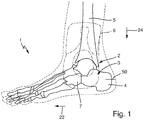
- Figure 1 shows a human foot 1 with an ankle 2. Below the ankle is a heel bone 3 with a heel bone 4. There is a shin bone 5 above the ankle 2. The fibula bone is not shown.
- the foot 1 out Figure 1 is a left foot and is seen from the outside of the foot. Also shown, using a dash-dotted line, is a conventional rail element 6 of a conventional ankle orthosis.
- the splint element 6 of the conventional orthosis extends from the shin bone 5 down to the front area of the heel bone 3 and covers a tarsal bone 7.
- FIG 2 An ankle orthosis 10 according to the invention is shown which is intended for use on a left foot.
- the ankle orthosis 10 has a base body 12 and a tensioning system 14 and a lateral rail element 16, which is designed as an upgradable rail element 16.
- the orthosis Figure 2 is in Figure 3 when looking at the inside of the foot - i.e. on the medial side - shown. In the representation of Figure 3 a medial rail element 18 is visible.
- the base body 12 of the orthosis 10 is formed from a flexible textile material and is inherently flexible.
- the basic shape of the base body 12 is boot-like, but it has an opening 20 towards the front.
- An arrow points forward and in the longitudinal direction of the foot 22. Accordingly, the proximal-distal direction 24 is identified by an arrow pointing in the distal direction.
- the base body 12 has a lower sole section 26 which forms a lower end of the base body 12.
- a rear contact section 28 of the base body 12 is arranged above the sole section 26 or its rear end.
- the rear abutment section 28 of the base body 12, which serves to abut the calf of the wearer on the base body 12, is spaced apart from the lower sole section by an opening 30 which serves to receive the heel bone.
- the sole section 26 ends flat in the rear area and then, viewed in the proximal direction, merges directly into the opening 30 for receiving the heel bone. In other words in rear area extends directly above the sole section 26, a free area or a material-free area, or an area not covered by the base body. This area then merges into the contact section 28 for contacting the wearer's calf.
- the tensioning system 14 has a plurality of belts 32 a - e.
- the straps 32 a and 32 b are arranged in the upper region of the rail elements 16, 18 and both engage at separate points 34a and 34b on the lateral rail element 16. They in turn end together at a turnbuckle 36, which is hooked into a hook point 38 and can then be swung into a lever-like position 40 point 40 and clipped there.
- the rail elements 16 and 18 are connected to one another via straps 42 with Velcro-based length adjustment.
- the tension belt 32 c is arranged in the lower region of the rail elements 16 and 18 and releasably connected to the medial rail element 18 via a clip connection 44.
- the tension belt 32 c can be released from the medial rail element 18 by pressing a push button 46.
- the straps 32d and 32e are arranged in the front area of the orthosis, these straps are connected to one another in one piece and fixed to the base body via a Velcro connection 48. You can loop or in the form of a so-called eight reins are placed around the wearer's ankle in order to achieve additional stabilization. Putting these belts on reduces the tension to the easily injured or already injured ankle ligament structures and counteracts the so-called talus advance.
- the medial splint element 18 extends in the applied state in the distal direction 24 as seen from the height of the tibial bone at least to the level of a center 50 of the heel bone 3. With its lower end 52, which is arranged in the distal direction 24 below the ankle joint 2, it extends further to the rear, therefore, seen against the longitudinal direction 22 of the foot, into the region of the heel bone 4, which the rail element 6 of the conventional ankle orthosis leaves uncovered.
- the medial splint element 18 of the orthosis 10 according to the invention extends to the position of the contact section 28.
- a rear end 54 in the lower region, that is to say in the region which is arranged below the ankle, of the medial splint element is when viewed in the lateral direction as he is in Figure 3 is shown at approximately the same height as regards the longitudinal direction 22 of the foot as the contact section 28 of the base body.
- FIG 3 A proximal half 58 of the orthosis is shown above an imaginary center line 60. Accordingly, in Figure 3 also a distal eighth 61 or a distal quarter 62 or a distal half 64 of the orthosis 10.
- the medial rail element 18 has an extension 70 which extends forward in the longitudinal direction 22 of the foot.
- the belt 32c acts on the extension 70 via a clip connection. In the applied state of the orthosis, this extension extends in the longitudinal direction of the foot beyond that part of the base body 12 which is arranged above the ankle and the extension comprises a front end 72 of the medial splint element 18.
- this front end 72 of the medial splint element 18 therefore extends beyond the part of the base body 12 which is arranged above the ankle in the applied state.
- the orthosis 10 On the underside of the orthosis 10, more precisely below the sole section 26, the orthosis 10 has a pliable or flexible but inelastic connecting element 80 between the two rail elements 16 and 18. This is designed as an inelastic belt 80 in order to fix a position of the rail elements relative to one another in the applied state.
- the connecting element 80 can also comprise two partial belts, the total length of which can be adjusted via a Velcro connection in order to be able to take the individual foot width into account.
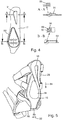
- FIG 4 the insertion element 17 of the lateral rail element 16 is shown in the state detached therefrom.
- the resiliently elastic and rigid insert element 17 can be connected to the upgradeable rigid, in the present case lateral, rail element 16.
- a first connection point 82 and a second connection point 84 are provided for connecting the insert element 17 to the upgradable rail element 16.
- the first connection point 82 is arranged in the upper region of the upgradeable rail element 16 and the second connection point 84 is arranged in the lower region of the upgradeable rail element 16.
- the insert element 17 extends in the distal direction parallel to the rail element 16.
- the insert element 17 is connected to the rail element 16 via a positive engagement at the respective connection points 82, 84.
- connection points 82, 84 of the insert element 17 is prevented from moving relative to the rail element 16 in the proximal-distal direction 24 and / or in the longitudinal direction 22 of the foot.
- the insert element 17 has projections 91 and 92 which extend in the lateral direction L and can be inserted into corresponding recesses 93 and 94 of the rail element 16.
- the projections 91 and 92 then rest with their side walls 95 and 96 extending in the lateral direction L. corresponding side walls of the recesses 93, 94. This creates protection against translational displacement in the proximal-distal direction or in the longitudinal direction of the foot.
- the projection 92 additionally has a further projection 98 which projects from the side walls 96 of the projection 92 and in which through the proximal-distal Direction 24 and the longitudinal foot direction 22 extends plane.
- the projection 92 has a groove 99, as it were, into which a region of the rail element 16 can be clipped.
- the groove 99 is formed around the protrusion 92.
- projections can also be provided on the rail element 16 instead of on the insert element 17 and corresponding recesses on the insert element 17.
- a projection on one of the two parts can also be provided at one of the connection points 82, 84 and an opening or recess at the other part and at the other connection point the exactly opposite constellation can be provided.
- the projections serve on the one hand to prevent displacement of the insertion element 17 relative to the Rail element 16 along its planar extent, ie essentially along the proximal-distal direction 24 and the longitudinal direction of the foot 22.
- the projections can have a rear grip via a type of groove or a further projection 98, which prevents loss in the lateral direction L or medial direction M.
- the captive device thus holds the insert element and the rail element together, so to speak, in a flat arrangement.
- the abutment of the projections 91 and 92 on their counterparts of the rail element 16 represents abutting abutment sections of the form-fitting rear grip.
- the rail element 16 and the insert element 17 lie in all four quadrants 101, 102, 103 and 104 which are defined by the proximal-distal direction 24 and the foot longitudinal direction 22 spanned plane against each other.
- it can also be a system in at least three of the four quadrants 101, 102, 103 and 104, the system being such that the area of the connection points 82, 84 of the insert element 17 is proximally relative to the rail element 16 -distal direction 24 and in the longitudinal direction 22 is prevented.
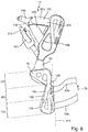
- the embodiment shown has a base body 12 which is open both towards the front and towards the rear.
- the base body 12 thus connects the rail elements 16, 18 only in the lower area.
- the medial splint element 18 extends in the intended applied state in the distal direction 24 viewed from above the ankle 2 downwards at least to the height of the center 50 of the heel bone 3 (in particular to the lower (distal) third, in particular to the lower Sixth; in the present case the medial splint element 18 merges into the sole section of the orthosis.).
- the medial splint element 18 With its lower end 100, which is arranged below the ankle joint 2, the medial splint element 18 extends rearward into the rear third, in particular the rear quarter, in particular the rear sixth, of the heel bone 3.
- the medial splint element 18 extends into the area of the heel bone 4. Furthermore, the medial splint element 18 in the two embodiments extends to the position of the contact section 28 for the calf.
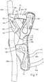
- the contact section 28 is in the applied state of the orthosis 10 formed by the two belts 42a and 42b. In the orthoses 10 from Figure 7 and Figure 8 no part of the base body 12 is arranged in the rear region between the belts 42a and 42b and the calf of the wearer. For padding, however, part of the base body 12 can be arranged here or a separate cushioning means. If a part of the base body 12 is arranged in the rear area between the belts 42a and 42b and the calf of the wearer, this also forms a contact section 28.
- the two front straps 32a and 32b serve to connect the rail elements 16, 18 in the region of the front of the lower leg.
- the two front straps 32a and 32b are designed as a strap 102, which is used to connect the rail elements 16, 18 in the region of the front of the lower leg.
- This belt 102 engages in the upper two thirds of the lateral rail element 16 at two spaced apart locations 104 and 106.
- the belt 102 comprises a connecting means 108 which corresponds to the tension lock 36 as shown in FIG Figure 3 is illustrated, is formed.
- a central section 110 of the belt 102 can be fastened or fixed to the medial rail element 18 via this connecting means. However, the middle section 110 can slide through the loop on the connecting means 108, so that the two legs 32a and 32b can automatically adapt to the individual circumstances.
- the belt 32c forms a front lower belt 112 which engages the lateral rail element 16 in the lower third thereof.
- the belt 112 in the present form has a connecting means 114 of a hook-like closure. This connecting means 114 serves to fasten the loose end of the belt to the medial rail element 18.
- the medial rail element 18 has a corresponding connection point 116.
- the connection point 116 is arranged on the extension 70 of the medial rail element 18.
- the two rail elements 16, 18 are in the case of the orthosis of Figure 7 connected via a part of the base body 12 forming a sole section and via the connecting element 80.
- the two rail elements 16, 18 are connected via the connecting element 80.
- the connecting element 80 extends between the two rail elements 16 and 18 and in the present case is designed to be variable in length.
- the connecting element 80 is designed as an inelastic belt 80. The relative position of the rail elements 16, 18 to one another in the applied state can be determined via the belt 80.
- the connecting element 80 can also comprise two partial belts, the total length of which can be adjusted via a Velcro connection in order to be able to take the individual foot width into account.
- the medial rail element 18 is essentially designed such that it extends in its lower third U3 essentially as far back as in FIG part of the rail element 18 lying above, which is illustrated by the line 119.
- the overlying part of the rail element 18 is formed by the upper third 03 and the middle third M3. Only in the area in which the lower rear belt 42b engages the medial rail element 18 does the rear edge of the medial rail element 18 protrude slightly further than in the lower region. This effectively forms an eyelet for attaching the rear lower strap 42b.
- the rear edge 120 of the medial splint element 18 extends in a straight line in the distal-proximal direction 24.
- the medial splint element extends further forward than in the part of the splint element 18 lying above it, on its front side or along its front edge the medial splint element has in its lower third U3 the forward extension 70, the prolongation 70 forming the most forwardly extending part of the medial splint element 18.
- the medial rail element initially has a protruding region 124 along its front edge 122 from above, which is then followed by a recessed region 126 in the distal direction.
Landscapes
- Health & Medical Sciences (AREA)
- Nursing (AREA)
- Orthopedic Medicine & Surgery (AREA)
- Engineering & Computer Science (AREA)
- Biomedical Technology (AREA)
- Heart & Thoracic Surgery (AREA)
- Vascular Medicine (AREA)
- Life Sciences & Earth Sciences (AREA)
- Animal Behavior & Ethology (AREA)
- General Health & Medical Sciences (AREA)
- Public Health (AREA)
- Veterinary Medicine (AREA)
- Orthopedics, Nursing, And Contraception (AREA)
- Prostheses (AREA)
Applications Claiming Priority (1)
| Application Number | Priority Date | Filing Date | Title |
|---|---|---|---|
| DE102018129472.7A DE102018129472A1 (de) | 2018-11-22 | 2018-11-22 | Sprunggelenksorthese |
Publications (3)
| Publication Number | Publication Date |
|---|---|
| EP3669832A2 true EP3669832A2 (fr) | 2020-06-24 |
| EP3669832A3 EP3669832A3 (fr) | 2020-10-28 |
| EP3669832B1 EP3669832B1 (fr) | 2022-04-13 |
Family
ID=68581177
Family Applications (1)
| Application Number | Title | Priority Date | Filing Date |
|---|---|---|---|
| EP19208452.3A Active EP3669832B1 (fr) | 2018-11-22 | 2019-11-12 | Orthèse de cheville |
Country Status (2)
| Country | Link |
|---|---|
| EP (1) | EP3669832B1 (fr) |
| DE (1) | DE102018129472A1 (fr) |
Family Cites Families (7)
| Publication number | Priority date | Publication date | Assignee | Title |
|---|---|---|---|---|
| US4727863A (en) * | 1986-05-30 | 1988-03-01 | Nelson Ronald E | Reinforced ankle brace |
| CH678808A5 (fr) * | 1989-08-03 | 1991-11-15 | Max Amrein | |
| US5199941A (en) * | 1992-03-13 | 1993-04-06 | Makinen Robbie W | Contoured ankle brace and stabilizer |
| DE19826900A1 (de) * | 1998-06-17 | 2000-01-05 | Sport Orthopaedie Schuhtechnik | Sprunggelenkorthese für die Behandlung fibularer Bandverletzungen |
| DE20115104U1 (de) * | 2001-09-13 | 2002-03-07 | Schrödel, Bodo, 96049 Bamberg | Sprunggelenkorthese |
| ES2556402T3 (es) * | 2011-02-28 | 2016-01-15 | Bsn Medical Gmbh | Ortesis tobillo-pie (OTP) |
| US9113997B2 (en) * | 2012-06-19 | 2015-08-25 | Tsan-Jee Chen | Ankle protecting device |
-
2018
- 2018-11-22 DE DE102018129472.7A patent/DE102018129472A1/de not_active Ceased
-
2019
- 2019-11-12 EP EP19208452.3A patent/EP3669832B1/fr active Active
Also Published As
| Publication number | Publication date |
|---|---|
| DE102018129472A1 (de) | 2020-05-28 |
| EP3669832B1 (fr) | 2022-04-13 |
| EP3669832A3 (fr) | 2020-10-28 |
Similar Documents
| Publication | Publication Date | Title |
|---|---|---|
| DE102009057700B3 (de) | Kniegelenkorthese | |
| DE10240121B4 (de) | Orthopädische Vorrichtung zur Korrektur von Zehenfehlstellungen | |
| DE102009038517B4 (de) | Baukastensystem zur Zusammenstellung einer Orthese für ein Knie und Verfahren zum Umbau einer Orthese aus diesem Baukastensystem | |
| EP2491895B1 (fr) | Orthèse de cheville | |
| EP3378448B1 (fr) | Orthèse du genou modulaire | |
| DE102006046928B4 (de) | Prothese mit einem Schaft zur Aufnahme eines Amputationsstumpfes | |
| DE102004020980A1 (de) | Modulare Hüftorthese | |
| EP2858606A1 (fr) | Orthèse | |
| DE19941368B4 (de) | Orthese zur Versorgung bei allgemeinen Fußhebeschwächen | |
| EP3669832B1 (fr) | Orthèse de cheville | |
| EP1675541B1 (fr) | Composite d'insertion ou d'ajustage de bandage | |
| EP2666445B1 (fr) | Orthèse de l'articulation de la cheville | |
| EP3068351B1 (fr) | Orthèse | |
| DE19844545B4 (de) | Gelenkorthese | |
| DE4418855A1 (de) | Knieorthese | |
| DE102018109784B4 (de) | Fußorthese zur Entlastung eines Fußes | |
| DE202016004074U1 (de) | Sprunggelenk-Orthese zum Stabilisieren eines menschlichen Sprunggelenks | |
| DE202020100382U1 (de) | Kniegelenkbandage | |
| DE102018111031B4 (de) | Sprunggelenk-Orthese | |
| DE19638683A1 (de) | Knöchelorthese | |
| DE102020134118A1 (de) | Vorrichtung zur Anlage an einem Unterschenkel | |
| DE19826900A1 (de) | Sprunggelenkorthese für die Behandlung fibularer Bandverletzungen | |
| DE102020101745A1 (de) | Kniegelenkbandage | |
| DE202020100383U1 (de) | Kniegelenkbandage | |
| DE202020106089U1 (de) | Kurze Orthese mit Einlage |
Legal Events
| Date | Code | Title | Description |
|---|---|---|---|
| PUAI | Public reference made under article 153(3) epc to a published international application that has entered the european phase |
Free format text: ORIGINAL CODE: 0009012 |
|
| STAA | Information on the status of an ep patent application or granted ep patent |
Free format text: STATUS: THE APPLICATION HAS BEEN PUBLISHED |
|
| AK | Designated contracting states |
Kind code of ref document: A2 Designated state(s): AL AT BE BG CH CY CZ DE DK EE ES FI FR GB GR HR HU IE IS IT LI LT LU LV MC MK MT NL NO PL PT RO RS SE SI SK SM TR |
|
| AX | Request for extension of the european patent |
Extension state: BA ME |
|
| PUAL | Search report despatched |
Free format text: ORIGINAL CODE: 0009013 |
|
| AK | Designated contracting states |
Kind code of ref document: A3 Designated state(s): AL AT BE BG CH CY CZ DE DK EE ES FI FR GB GR HR HU IE IS IT LI LT LU LV MC MK MT NL NO PL PT RO RS SE SI SK SM TR |
|
| AX | Request for extension of the european patent |
Extension state: BA ME |
|
| RIC1 | Information provided on ipc code assigned before grant |
Ipc: A61F 5/01 20060101AFI20200918BHEP |
|
| STAA | Information on the status of an ep patent application or granted ep patent |
Free format text: STATUS: REQUEST FOR EXAMINATION WAS MADE |
|
| 17P | Request for examination filed |
Effective date: 20210414 |
|
| RBV | Designated contracting states (corrected) |
Designated state(s): AL AT BE BG CH CY CZ DE DK EE ES FI FR GB GR HR HU IE IS IT LI LT LU LV MC MK MT NL NO PL PT RO RS SE SI SK SM TR |
|
| GRAP | Despatch of communication of intention to grant a patent |
Free format text: ORIGINAL CODE: EPIDOSNIGR1 |
|
| STAA | Information on the status of an ep patent application or granted ep patent |
Free format text: STATUS: GRANT OF PATENT IS INTENDED |
|
| INTG | Intention to grant announced |
Effective date: 20211026 |
|
| GRAS | Grant fee paid |
Free format text: ORIGINAL CODE: EPIDOSNIGR3 |
|
| GRAA | (expected) grant |
Free format text: ORIGINAL CODE: 0009210 |
|
| STAA | Information on the status of an ep patent application or granted ep patent |
Free format text: STATUS: THE PATENT HAS BEEN GRANTED |
|
| AK | Designated contracting states |
Kind code of ref document: B1 Designated state(s): AL AT BE BG CH CY CZ DE DK EE ES FI FR GB GR HR HU IE IS IT LI LT LU LV MC MK MT NL NO PL PT RO RS SE SI SK SM TR |
|
| REG | Reference to a national code |
Ref country code: GB Ref legal event code: FG4D Free format text: NOT ENGLISH |
|
| REG | Reference to a national code |
Ref country code: CH Ref legal event code: EP |
|
| REG | Reference to a national code |
Ref country code: DE Ref legal event code: R096 Ref document number: 502019004047 Country of ref document: DE |
|
| REG | Reference to a national code |
Ref country code: IE Ref legal event code: FG4D Free format text: LANGUAGE OF EP DOCUMENT: GERMAN |
|
| REG | Reference to a national code |
Ref country code: AT Ref legal event code: REF Ref document number: 1482826 Country of ref document: AT Kind code of ref document: T Effective date: 20220515 |
|
| REG | Reference to a national code |
Ref country code: LT Ref legal event code: MG9D |
|
| REG | Reference to a national code |
Ref country code: NL Ref legal event code: MP Effective date: 20220413 |
|
| PG25 | Lapsed in a contracting state [announced via postgrant information from national office to epo] |
Ref country code: NL Free format text: LAPSE BECAUSE OF FAILURE TO SUBMIT A TRANSLATION OF THE DESCRIPTION OR TO PAY THE FEE WITHIN THE PRESCRIBED TIME-LIMIT Effective date: 20220413 |
|
| PG25 | Lapsed in a contracting state [announced via postgrant information from national office to epo] |
Ref country code: SE Free format text: LAPSE BECAUSE OF FAILURE TO SUBMIT A TRANSLATION OF THE DESCRIPTION OR TO PAY THE FEE WITHIN THE PRESCRIBED TIME-LIMIT Effective date: 20220413 Ref country code: PT Free format text: LAPSE BECAUSE OF FAILURE TO SUBMIT A TRANSLATION OF THE DESCRIPTION OR TO PAY THE FEE WITHIN THE PRESCRIBED TIME-LIMIT Effective date: 20220816 Ref country code: NO Free format text: LAPSE BECAUSE OF FAILURE TO SUBMIT A TRANSLATION OF THE DESCRIPTION OR TO PAY THE FEE WITHIN THE PRESCRIBED TIME-LIMIT Effective date: 20220713 Ref country code: LT Free format text: LAPSE BECAUSE OF FAILURE TO SUBMIT A TRANSLATION OF THE DESCRIPTION OR TO PAY THE FEE WITHIN THE PRESCRIBED TIME-LIMIT Effective date: 20220413 Ref country code: HR Free format text: LAPSE BECAUSE OF FAILURE TO SUBMIT A TRANSLATION OF THE DESCRIPTION OR TO PAY THE FEE WITHIN THE PRESCRIBED TIME-LIMIT Effective date: 20220413 Ref country code: GR Free format text: LAPSE BECAUSE OF FAILURE TO SUBMIT A TRANSLATION OF THE DESCRIPTION OR TO PAY THE FEE WITHIN THE PRESCRIBED TIME-LIMIT Effective date: 20220714 Ref country code: FI Free format text: LAPSE BECAUSE OF FAILURE TO SUBMIT A TRANSLATION OF THE DESCRIPTION OR TO PAY THE FEE WITHIN THE PRESCRIBED TIME-LIMIT Effective date: 20220413 Ref country code: ES Free format text: LAPSE BECAUSE OF FAILURE TO SUBMIT A TRANSLATION OF THE DESCRIPTION OR TO PAY THE FEE WITHIN THE PRESCRIBED TIME-LIMIT Effective date: 20220413 Ref country code: BG Free format text: LAPSE BECAUSE OF FAILURE TO SUBMIT A TRANSLATION OF THE DESCRIPTION OR TO PAY THE FEE WITHIN THE PRESCRIBED TIME-LIMIT Effective date: 20220713 |
|
| PG25 | Lapsed in a contracting state [announced via postgrant information from national office to epo] |
Ref country code: RS Free format text: LAPSE BECAUSE OF FAILURE TO SUBMIT A TRANSLATION OF THE DESCRIPTION OR TO PAY THE FEE WITHIN THE PRESCRIBED TIME-LIMIT Effective date: 20220413 Ref country code: PL Free format text: LAPSE BECAUSE OF FAILURE TO SUBMIT A TRANSLATION OF THE DESCRIPTION OR TO PAY THE FEE WITHIN THE PRESCRIBED TIME-LIMIT Effective date: 20220413 Ref country code: LV Free format text: LAPSE BECAUSE OF FAILURE TO SUBMIT A TRANSLATION OF THE DESCRIPTION OR TO PAY THE FEE WITHIN THE PRESCRIBED TIME-LIMIT Effective date: 20220413 Ref country code: IS Free format text: LAPSE BECAUSE OF FAILURE TO SUBMIT A TRANSLATION OF THE DESCRIPTION OR TO PAY THE FEE WITHIN THE PRESCRIBED TIME-LIMIT Effective date: 20220813 |
|
| REG | Reference to a national code |
Ref country code: DE Ref legal event code: R097 Ref document number: 502019004047 Country of ref document: DE |
|
| PG25 | Lapsed in a contracting state [announced via postgrant information from national office to epo] |
Ref country code: SM Free format text: LAPSE BECAUSE OF FAILURE TO SUBMIT A TRANSLATION OF THE DESCRIPTION OR TO PAY THE FEE WITHIN THE PRESCRIBED TIME-LIMIT Effective date: 20220413 Ref country code: SK Free format text: LAPSE BECAUSE OF FAILURE TO SUBMIT A TRANSLATION OF THE DESCRIPTION OR TO PAY THE FEE WITHIN THE PRESCRIBED TIME-LIMIT Effective date: 20220413 Ref country code: RO Free format text: LAPSE BECAUSE OF FAILURE TO SUBMIT A TRANSLATION OF THE DESCRIPTION OR TO PAY THE FEE WITHIN THE PRESCRIBED TIME-LIMIT Effective date: 20220413 Ref country code: EE Free format text: LAPSE BECAUSE OF FAILURE TO SUBMIT A TRANSLATION OF THE DESCRIPTION OR TO PAY THE FEE WITHIN THE PRESCRIBED TIME-LIMIT Effective date: 20220413 Ref country code: DK Free format text: LAPSE BECAUSE OF FAILURE TO SUBMIT A TRANSLATION OF THE DESCRIPTION OR TO PAY THE FEE WITHIN THE PRESCRIBED TIME-LIMIT Effective date: 20220413 Ref country code: CZ Free format text: LAPSE BECAUSE OF FAILURE TO SUBMIT A TRANSLATION OF THE DESCRIPTION OR TO PAY THE FEE WITHIN THE PRESCRIBED TIME-LIMIT Effective date: 20220413 |
|
| PLBE | No opposition filed within time limit |
Free format text: ORIGINAL CODE: 0009261 |
|
| STAA | Information on the status of an ep patent application or granted ep patent |
Free format text: STATUS: NO OPPOSITION FILED WITHIN TIME LIMIT |
|
| 26N | No opposition filed |
Effective date: 20230116 |
|
| PG25 | Lapsed in a contracting state [announced via postgrant information from national office to epo] |
Ref country code: AL Free format text: LAPSE BECAUSE OF FAILURE TO SUBMIT A TRANSLATION OF THE DESCRIPTION OR TO PAY THE FEE WITHIN THE PRESCRIBED TIME-LIMIT Effective date: 20220413 |
|
| PG25 | Lapsed in a contracting state [announced via postgrant information from national office to epo] |
Ref country code: SI Free format text: LAPSE BECAUSE OF FAILURE TO SUBMIT A TRANSLATION OF THE DESCRIPTION OR TO PAY THE FEE WITHIN THE PRESCRIBED TIME-LIMIT Effective date: 20220413 |
|
| P01 | Opt-out of the competence of the unified patent court (upc) registered |
Effective date: 20230524 |
|
| PG25 | Lapsed in a contracting state [announced via postgrant information from national office to epo] |
Ref country code: MC Free format text: LAPSE BECAUSE OF FAILURE TO SUBMIT A TRANSLATION OF THE DESCRIPTION OR TO PAY THE FEE WITHIN THE PRESCRIBED TIME-LIMIT Effective date: 20220413 |
|
| REG | Reference to a national code |
Ref country code: BE Ref legal event code: MM Effective date: 20221130 |
|
| PG25 | Lapsed in a contracting state [announced via postgrant information from national office to epo] |
Ref country code: LU Free format text: LAPSE BECAUSE OF NON-PAYMENT OF DUE FEES Effective date: 20221112 |
|
| PG25 | Lapsed in a contracting state [announced via postgrant information from national office to epo] |
Ref country code: IE Free format text: LAPSE BECAUSE OF NON-PAYMENT OF DUE FEES Effective date: 20221112 |
|
| PG25 | Lapsed in a contracting state [announced via postgrant information from national office to epo] |
Ref country code: FR Free format text: LAPSE BECAUSE OF NON-PAYMENT OF DUE FEES Effective date: 20221130 Ref country code: BE Free format text: LAPSE BECAUSE OF NON-PAYMENT OF DUE FEES Effective date: 20221130 |
|
| PG25 | Lapsed in a contracting state [announced via postgrant information from national office to epo] |
Ref country code: IT Free format text: LAPSE BECAUSE OF FAILURE TO SUBMIT A TRANSLATION OF THE DESCRIPTION OR TO PAY THE FEE WITHIN THE PRESCRIBED TIME-LIMIT Effective date: 20220413 |
|
| PG25 | Lapsed in a contracting state [announced via postgrant information from national office to epo] |
Ref country code: HU Free format text: LAPSE BECAUSE OF FAILURE TO SUBMIT A TRANSLATION OF THE DESCRIPTION OR TO PAY THE FEE WITHIN THE PRESCRIBED TIME-LIMIT; INVALID AB INITIO Effective date: 20191112 |
|
| PG25 | Lapsed in a contracting state [announced via postgrant information from national office to epo] |
Ref country code: CY Free format text: LAPSE BECAUSE OF FAILURE TO SUBMIT A TRANSLATION OF THE DESCRIPTION OR TO PAY THE FEE WITHIN THE PRESCRIBED TIME-LIMIT Effective date: 20220413 |
|
| PG25 | Lapsed in a contracting state [announced via postgrant information from national office to epo] |
Ref country code: MK Free format text: LAPSE BECAUSE OF FAILURE TO SUBMIT A TRANSLATION OF THE DESCRIPTION OR TO PAY THE FEE WITHIN THE PRESCRIBED TIME-LIMIT Effective date: 20220413 |
|
| PG25 | Lapsed in a contracting state [announced via postgrant information from national office to epo] |
Ref country code: TR Free format text: LAPSE BECAUSE OF FAILURE TO SUBMIT A TRANSLATION OF THE DESCRIPTION OR TO PAY THE FEE WITHIN THE PRESCRIBED TIME-LIMIT Effective date: 20220413 |
|
| GBPC | Gb: european patent ceased through non-payment of renewal fee |
Effective date: 20231112 |
|
| PG25 | Lapsed in a contracting state [announced via postgrant information from national office to epo] |
Ref country code: MT Free format text: LAPSE BECAUSE OF FAILURE TO SUBMIT A TRANSLATION OF THE DESCRIPTION OR TO PAY THE FEE WITHIN THE PRESCRIBED TIME-LIMIT Effective date: 20220413 |
|
| PG25 | Lapsed in a contracting state [announced via postgrant information from national office to epo] |
Ref country code: GB Free format text: LAPSE BECAUSE OF NON-PAYMENT OF DUE FEES Effective date: 20231112 |
|
| PG25 | Lapsed in a contracting state [announced via postgrant information from national office to epo] |
Ref country code: GB Free format text: LAPSE BECAUSE OF NON-PAYMENT OF DUE FEES Effective date: 20231112 |
|
| PG25 | Lapsed in a contracting state [announced via postgrant information from national office to epo] |
Ref country code: BG Free format text: LAPSE BECAUSE OF FAILURE TO SUBMIT A TRANSLATION OF THE DESCRIPTION OR TO PAY THE FEE WITHIN THE PRESCRIBED TIME-LIMIT Effective date: 20220413 |
|
| PG25 | Lapsed in a contracting state [announced via postgrant information from national office to epo] |
Ref country code: BG Free format text: LAPSE BECAUSE OF FAILURE TO SUBMIT A TRANSLATION OF THE DESCRIPTION OR TO PAY THE FEE WITHIN THE PRESCRIBED TIME-LIMIT Effective date: 20220413 |
|
| REG | Reference to a national code |
Ref country code: CH Ref legal event code: U11 Free format text: ST27 STATUS EVENT CODE: U-0-0-U10-U11 (AS PROVIDED BY THE NATIONAL OFFICE) Effective date: 20251201 |
|
| PG25 | Lapsed in a contracting state [announced via postgrant information from national office to epo] |
Ref country code: AT Free format text: LAPSE BECAUSE OF NON-PAYMENT OF DUE FEES Effective date: 20241112 |
|
| REG | Reference to a national code |
Ref country code: AT Ref legal event code: MM01 Ref document number: 1482826 Country of ref document: AT Kind code of ref document: T Effective date: 20241112 |
|
| PGFP | Annual fee paid to national office [announced via postgrant information from national office to epo] |
Ref country code: CH Payment date: 20251201 Year of fee payment: 7 |
|
| PGFP | Annual fee paid to national office [announced via postgrant information from national office to epo] |
Ref country code: DE Payment date: 20260119 Year of fee payment: 7 |
|
| PGFP | Annual fee paid to national office [announced via postgrant information from national office to epo] |
Ref country code: AT Payment date: 20260410 Year of fee payment: 5 |