EP3669926A1 - Cathéter à ballonnet ainsi que procédé et dispositif de fabrication du cathéter à ballonnet - Google Patents
Cathéter à ballonnet ainsi que procédé et dispositif de fabrication du cathéter à ballonnet Download PDFInfo
- Publication number
- EP3669926A1 EP3669926A1 EP18213575.6A EP18213575A EP3669926A1 EP 3669926 A1 EP3669926 A1 EP 3669926A1 EP 18213575 A EP18213575 A EP 18213575A EP 3669926 A1 EP3669926 A1 EP 3669926A1
- Authority
- EP
- European Patent Office
- Prior art keywords
- inner shaft
- balloon
- distal end
- balloon catheter
- end section
- Prior art date
- Legal status (The legal status is an assumption and is not a legal conclusion. Google has not performed a legal analysis and makes no representation as to the accuracy of the status listed.)
- Withdrawn
Links
- 238000004519 manufacturing process Methods 0.000 title claims description 8
- 238000000034 method Methods 0.000 title abstract description 9
- 239000000463 material Substances 0.000 claims abstract description 100
- -1 polyethylene Polymers 0.000 claims description 19
- 239000004698 Polyethylene Substances 0.000 claims description 18
- 229920000573 polyethylene Polymers 0.000 claims description 18
- 229920000299 Nylon 12 Polymers 0.000 claims description 11
- 239000002318 adhesion promoter Substances 0.000 claims description 8
- 229920001903 high density polyethylene Polymers 0.000 claims description 8
- 239000004700 high-density polyethylene Substances 0.000 claims description 8
- 239000000126 substance Substances 0.000 claims description 8
- 239000004952 Polyamide Substances 0.000 claims description 6
- 238000003754 machining Methods 0.000 claims description 6
- 239000002245 particle Substances 0.000 claims description 6
- 229920002647 polyamide Polymers 0.000 claims description 6
- 229920000092 linear low density polyethylene Polymers 0.000 description 7
- 239000004707 linear low-density polyethylene Substances 0.000 description 7
- 230000032798 delamination Effects 0.000 description 6
- 238000003801 milling Methods 0.000 description 5
- 229920002614 Polyether block amide Polymers 0.000 description 4
- VGGSQFUCUMXWEO-UHFFFAOYSA-N Ethene Chemical compound C=C VGGSQFUCUMXWEO-UHFFFAOYSA-N 0.000 description 3
- 229920000571 Nylon 11 Polymers 0.000 description 3
- 229920002292 Nylon 6 Polymers 0.000 description 3
- 239000004840 adhesive resin Substances 0.000 description 3
- 229920006223 adhesive resin Polymers 0.000 description 3
- 238000000608 laser ablation Methods 0.000 description 3
- 229920000139 polyethylene terephthalate Polymers 0.000 description 3
- 239000005020 polyethylene terephthalate Substances 0.000 description 3
- 229920000915 polyvinyl chloride Polymers 0.000 description 3
- 239000004800 polyvinyl chloride Substances 0.000 description 3
- JHWNWJKBPDFINM-UHFFFAOYSA-N Laurolactam Chemical compound O=C1CCCCCCCCCCCN1 JHWNWJKBPDFINM-UHFFFAOYSA-N 0.000 description 2
- 229920000305 Nylon 6,10 Polymers 0.000 description 2
- 229920000572 Nylon 6/12 Polymers 0.000 description 2
- KRADHMIOFJQKEZ-UHFFFAOYSA-N Tri-2-ethylhexyl trimellitate Chemical compound CCCCC(CC)COC(=O)C1=CC=C(C(=O)OCC(CC)CCCC)C(C(=O)OCC(CC)CCCC)=C1 KRADHMIOFJQKEZ-UHFFFAOYSA-N 0.000 description 2
- 239000000853 adhesive Substances 0.000 description 2
- 238000002399 angioplasty Methods 0.000 description 2
- 238000005553 drilling Methods 0.000 description 2
- 239000003814 drug Substances 0.000 description 2
- 229940079593 drug Drugs 0.000 description 2
- 239000005038 ethylene vinyl acetate Substances 0.000 description 2
- 239000012530 fluid Substances 0.000 description 2
- 229920001684 low density polyethylene Polymers 0.000 description 2
- 239000004702 low-density polyethylene Substances 0.000 description 2
- 229920001200 poly(ethylene-vinyl acetate) Polymers 0.000 description 2
- 229920000728 polyester Polymers 0.000 description 2
- 229920001343 polytetrafluoroethylene Polymers 0.000 description 2
- 239000004810 polytetrafluoroethylene Substances 0.000 description 2
- 238000003466 welding Methods 0.000 description 2
- 239000005977 Ethylene Substances 0.000 description 1
- 229920003300 Plexar® Polymers 0.000 description 1
- 239000004433 Thermoplastic polyurethane Substances 0.000 description 1
- 239000002253 acid Substances 0.000 description 1
- 230000001070 adhesive effect Effects 0.000 description 1
- 238000010276 construction Methods 0.000 description 1
- 238000001816 cooling Methods 0.000 description 1
- 229920001577 copolymer Polymers 0.000 description 1
- 239000007822 coupling agent Substances 0.000 description 1
- 238000005520 cutting process Methods 0.000 description 1
- 229920001971 elastomer Polymers 0.000 description 1
- 239000000806 elastomer Substances 0.000 description 1
- HDERJYVLTPVNRI-UHFFFAOYSA-N ethene;ethenyl acetate Chemical compound C=C.CC(=O)OC=C HDERJYVLTPVNRI-UHFFFAOYSA-N 0.000 description 1
- 229920006225 ethylene-methyl acrylate Polymers 0.000 description 1
- 229920002313 fluoropolymer Polymers 0.000 description 1
- 239000002783 friction material Substances 0.000 description 1
- 238000002513 implantation Methods 0.000 description 1
- 230000000149 penetrating effect Effects 0.000 description 1
- 239000004014 plasticizer Substances 0.000 description 1
- 229920000642 polymer Polymers 0.000 description 1
- 229920000098 polyolefin Polymers 0.000 description 1
- 229920002635 polyurethane Polymers 0.000 description 1
- 239000004814 polyurethane Substances 0.000 description 1
- DJZKNOVUNYPPEE-UHFFFAOYSA-N tetradecane-1,4,11,14-tetracarboxamide Chemical compound NC(=O)CCCC(C(N)=O)CCCCCCC(C(N)=O)CCCC(N)=O DJZKNOVUNYPPEE-UHFFFAOYSA-N 0.000 description 1
- 229920001169 thermoplastic Polymers 0.000 description 1
- 229920002803 thermoplastic polyurethane Polymers 0.000 description 1
- 239000004416 thermosoftening plastic Substances 0.000 description 1
Images

Classifications
-
- A—HUMAN NECESSITIES
- A61—MEDICAL OR VETERINARY SCIENCE; HYGIENE
- A61M—DEVICES FOR INTRODUCING MEDIA INTO, OR ONTO, THE BODY; DEVICES FOR TRANSDUCING BODY MEDIA OR FOR TAKING MEDIA FROM THE BODY; DEVICES FOR PRODUCING OR ENDING SLEEP OR STUPOR
- A61M25/00—Catheters; Hollow probes
- A61M25/10—Balloon catheters
- A61M25/1006—Balloons formed between concentric tubes
-
- A—HUMAN NECESSITIES
- A61—MEDICAL OR VETERINARY SCIENCE; HYGIENE
- A61M—DEVICES FOR INTRODUCING MEDIA INTO, OR ONTO, THE BODY; DEVICES FOR TRANSDUCING BODY MEDIA OR FOR TAKING MEDIA FROM THE BODY; DEVICES FOR PRODUCING OR ENDING SLEEP OR STUPOR
- A61M25/00—Catheters; Hollow probes
- A61M25/0009—Making of catheters or other medical or surgical tubes
- A61M25/0013—Weakening parts of a catheter tubing, e.g. by making cuts in the tube or reducing thickness of a layer at one point to adjust the flexibility
-
- A—HUMAN NECESSITIES
- A61—MEDICAL OR VETERINARY SCIENCE; HYGIENE
- A61M—DEVICES FOR INTRODUCING MEDIA INTO, OR ONTO, THE BODY; DEVICES FOR TRANSDUCING BODY MEDIA OR FOR TAKING MEDIA FROM THE BODY; DEVICES FOR PRODUCING OR ENDING SLEEP OR STUPOR
- A61M25/00—Catheters; Hollow probes
- A61M25/10—Balloon catheters
-
- A—HUMAN NECESSITIES
- A61—MEDICAL OR VETERINARY SCIENCE; HYGIENE
- A61M—DEVICES FOR INTRODUCING MEDIA INTO, OR ONTO, THE BODY; DEVICES FOR TRANSDUCING BODY MEDIA OR FOR TAKING MEDIA FROM THE BODY; DEVICES FOR PRODUCING OR ENDING SLEEP OR STUPOR
- A61M25/00—Catheters; Hollow probes
- A61M25/10—Balloon catheters
- A61M25/1027—Making of balloon catheters
- A61M25/1034—Joining of shaft and balloon
-
- A—HUMAN NECESSITIES
- A61—MEDICAL OR VETERINARY SCIENCE; HYGIENE
- A61M—DEVICES FOR INTRODUCING MEDIA INTO, OR ONTO, THE BODY; DEVICES FOR TRANSDUCING BODY MEDIA OR FOR TAKING MEDIA FROM THE BODY; DEVICES FOR PRODUCING OR ENDING SLEEP OR STUPOR
- A61M25/00—Catheters; Hollow probes
- A61M25/10—Balloon catheters
- A61M25/1027—Making of balloon catheters
- A61M25/1036—Making parts for balloon catheter systems, e.g. shafts or distal ends
-
- A—HUMAN NECESSITIES
- A61—MEDICAL OR VETERINARY SCIENCE; HYGIENE
- A61M—DEVICES FOR INTRODUCING MEDIA INTO, OR ONTO, THE BODY; DEVICES FOR TRANSDUCING BODY MEDIA OR FOR TAKING MEDIA FROM THE BODY; DEVICES FOR PRODUCING OR ENDING SLEEP OR STUPOR
- A61M25/00—Catheters; Hollow probes
- A61M25/10—Balloon catheters
- A61M25/104—Balloon catheters used for angioplasty
-
- A—HUMAN NECESSITIES
- A61—MEDICAL OR VETERINARY SCIENCE; HYGIENE
- A61F—FILTERS IMPLANTABLE INTO BLOOD VESSELS; PROSTHESES; DEVICES PROVIDING PATENCY TO, OR PREVENTING COLLAPSING OF, TUBULAR STRUCTURES OF THE BODY, e.g. STENTS; ORTHOPAEDIC, NURSING OR CONTRACEPTIVE DEVICES; FOMENTATION; TREATMENT OR PROTECTION OF EYES OR EARS; BANDAGES, DRESSINGS OR ABSORBENT PADS; FIRST-AID KITS
- A61F2/00—Filters implantable into blood vessels; Prostheses, i.e. artificial substitutes or replacements for parts of the body; Appliances for connecting them with the body; Devices providing patency to, or preventing collapsing of, tubular structures of the body, e.g. stents
- A61F2/95—Instruments specially adapted for placement or removal of stents or stent-grafts
- A61F2/958—Inflatable balloons for placing stents or stent-grafts
Definitions
- the invention relates to a balloon catheter and a method and a device for producing such a balloon catheter.
- the present invention is based on the object of providing a balloon catheter or a method for producing the balloon catheter which has no delamination of a multi-layer inner shaft in the welding area of the balloon.
- the section of the inner shaft arranged in the balloon interior has a plurality of material layers lying one above the other and connected to one another, which surround a lumen of the inner shaft, whereas the distal end section of the inner shaft is formed in one layer.
- distal denotes a component or a region of the balloon catheter that is further away along the course of the balloon catheter from a person (doctor) handling the balloon catheter during implantation as a corresponding proximal component or proximal region of the Catheters.
- the section (32) of the inner shaft (3) arranged in the balloon interior (20) has at least one outermost material layer (3a) and one innermost material layer (3c), the distal end section (31) of the inner shaft (3) is formed by the outermost layer of material
- the section of the inner shaft arranged in the balloon interior has an outermost material layer, the extension of which forms the distal end section of the inner shaft.
- a plurality of superimposed and interconnected material layers are provided for the section of the inner shaft arranged in the balloon interior.
- the number of layers of material lying one above the other and connected to one another should in principle only be limited by technical circumstances.
- Today, for example, eight layers of material lying on top of one another and connected to one another can be produced by coextrusion.
- the section (32) of the inner shaft (3) arranged in the balloon interior (20) has at least three material layers.
- the outermost material layer is formed from one of the following substances: a polyamide, preferably polycaprolactam (PA 6, CAS number 25038-54-4 ), Poly- ( N, N'- hexamethylene adipidiamide (poly (hexamethylene adipamide, PA 6.6, CAS number 32131-17-2 ), Poly (hexamethylene sebacamide) (PA 6.10, CAS number 9011-52-3 ), Poly (hexamethylene dodecanediamide) (PA 6.12, CAS number 26098-55-5 ), Polyundecanolactam (PA 11, CAS number 25035-04-5 ) and polylauryl lactam ( CAS No.
- a polyamide preferably polycaprolactam (PA 6, CAS number 25038-54-4 )
- Poly- N, N'- hexamethylene adipidiamide (poly (hexamethylene adipamide, PA 6.6, CAS number 32131-17-2 )
- Peba elastomers such as polyether block amides, preferably the one with CAS No. 77402-38-1 , but also those with the designation Pebax (trade name) xx SA 01 MED, where xx can be 2533, 3533, 4033, 4533, 5533, 6333, 7033, 7233 or MV 1074, polyethylene terephthalate (PET, CAS No. 25038-59-9 ) and thermoplastic polyurethane, for example the one with CAS No. 75701-44-9
- polyester or polyvinyl chloride can be used, especially in combination with plasticizers such as tris (2-ethylhexyl) trimellitate CAS No. 3319-31-1 .
- the outermost material layer can be selected from the group comprising or consisting of polyamide, polycaprolactam, poly ( N, N'- hexamethylene adipidiamide , poly (hexamethylene sebacamide), poly (hexamethylene dodecanediamide), polyundecanolactam, polylauryl lactam, polyether block amide, Pebax, polyethylene terephthalate, polyurethane, polyester and polyvinyl chloride.
- the outermost material layer is formed from a polyamide mentioned herein.
- the portion of the inner shaft arranged in the balloon interior has an innermost low-friction material layer, the innermost material layer preferably being formed from one of the following materials: polyethylene (PE), in particular high-density polyethylene (HDPE) such as, for example CAS No. 9002-88-4 , or fluorinated polymers, in particular fluorinated polyolefins such as polytetrafluoroethylene (PTFE) such as with CAS No. 9002-84-0 .
- PE polyethylene
- HDPE high-density polyethylene
- PTFE polytetrafluoroethylene
- HDPE is polyethylene with weakly branched polymer chains, so that there is a high density, which is in particular between 0.94 g / cm 3 and 0.97 g / cm 3 .
- the innermost material layer is connected to the outermost material layer via a middle material layer of the section of the inner shaft arranged in the interior of the balloon.
- the middle layer of material can perform the function of an adhesion promoter between the outermost and the innermost layer of material.
- said middle material layer is formed from a polyethylene adhesion promoter.
- Suitable polyethylene adhesion promoters are preferably selected from the group comprising or consisting of low-density polyethylene (LDPE, "low density"), in particular and preferably linear low-density polyethylene (LLDPE, linear low density polyethylene), ethylene-based copolymers such as, for example, ethylene Vinyl acetate copolymer, such as the one with CAS No. 24937-78-8 or ethylene-methyl acrylate copolymer, and polyethylene-based adhesive resins such as, for example, maleic anhydride-modified polyethylene-based adhesive resins.
- LLDPE low-density polyethylene
- LLDPE linear low-density polyethylene
- ethylene-based copolymers such as, for example, ethylene Vinyl acetate copolymer, such as the one with CAS No. 24937-78-8 or ethylene-methyl acrylate copolymer
- polyethylene-based adhesive resins such
- the density of the polyethylene adhesion promoters is preferably between 0.91 g / cm 3 and 0.93 g / cm 3 .
- the distal end section of the balloon is further connected to a tip of the balloon catheter, which protrudes in sections from the distal end section of the balloon, the tip further being connected to the distal end section of the inner shaft.
- the lumen of the inner shaft is designed to receive a guide wire, the guide wire being able to be guided out of the balloon catheter in particular via the tip.
- the balloon catheter has an outer shaft which surrounds a lumen, the inner shaft being arranged in the lumen of the outer shaft and being led out of the lumen of the outer shaft at a distal end section of the outer shaft.
- the interior of the balloon can be acted upon with a fluid medium for unfolding the balloon via the outer shaft.
- the section of the inner shaft arranged in the balloon interior adjoins a proximal section of the inner shaft, which is guided in the outer shaft and can also extend outside the balloon interior.
- the proximal section also preferably has the plurality of superimposed and interconnected material layers.
- the balloon has a proximal end section which is connected to the distal end section of the outer shaft.
- the three material layers are designed in such a way that the outermost material layer consists of polylauryllactam (nylon 12) and the innermost layer consists of high-density polyethylene, a polyethylene adhesion promoter, preferably LLDPE, being arranged between the outermost and innermost material layer.
- the outermost material layer consists of polylauryllactam (nylon 12) and the innermost layer consists of high-density polyethylene, a polyethylene adhesion promoter, preferably LLDPE, being arranged between the outermost and innermost material layer.
- the three material layers are designed such that the outermost material layer consists of polyvinyl chloride and the innermost layer consists of high-density polyethylene, a polyethylene adhesive agent being arranged between the outermost and innermost material layer, preferably of ethylene-vinyl acetate copolymer.
- the material layers on the distal end section of the inner shaft, apart from the outermost material layer, are removed by means of a machining process, in particular by drilling with a drill, reaming with a reamer or milling with a milling head.
- the device described below can be used for this.
- the material layers on the distal end section of the inner shaft are removed except for the outermost material layer by means of a laser ablation, preferably by means of a femtosecond laser.
- the outermost material layer is formed from one of the substances proposed here, and is preferably formed from one of the following substances: a polyamide, in particular polylauryl lactam (PA 12).
- a polyamide in particular polylauryl lactam (PA 12).
- the inner shaft has an innermost material layer, the innermost material layer preferably being formed from one of the substances proposed here, and preferably being formed from one of the following substances: polyethylene (PE), preferably HDPE.
- PE polyethylene
- the innermost material layer is connected to the outermost material layer via a middle material layer of the inner shaft, the middle material layer in particular forming an adhesion promoter between the outermost and the innermost material layer, and in particular the middle material layer consisting of a of the substances proposed herein, and is preferably formed from a polyethylene coupling agent such as LLDPE.
- the innermost material layer and the middle material layer are preferably removed by means of the machining process (for example by means of a drill, a reamer or a milling head) such that the distal end section of the inner shaft is only formed by the outer material layer.
- the innermost material layer and the middle material layer are removed using laser ablation (e.g. using a femtosecond laser).
- a region of the outermost material layer on an inner side of the distal end section of the inner shaft facing the lumen of the inner shaft can be removed such that the distal end section connects to a remaining section of the inner shaft via a circumferential step.
- the distal end portion of the balloon can be connected to the distal end portion of the inner shaft, e.g. by fixing the distal end portion of the balloon on the distal end portion of the inner shaft, e.g. is welded to the distal end portion of the inner shaft by means of a shrink tube and by means of a laser.
- the distal end portion of the balloon can be connected to the distal end portion of the inner shaft, e.g. by fixing the distal end portion of the balloon on the distal end portion of the inner shaft, e.g. is welded to the distal end portion of the inner shaft by means of a shrink tube, and by means of a laser, and then said material layers are removed.
- proximal end section of the balloon can be connected to a distal end section of the outer shaft of the balloon catheter, wherein the inner shaft together with the distal end section can be led out of a lumen of the outer shaft at the distal end section of the outer shaft.
- the balloon can be folded in a known manner.
- a stent in particular a drug-coated stent, can be crimped onto the balloon in a known manner.
- the stent can later be implanted into a patient's vessel using the balloon catheter (e.g. in the case of angioplasty), the stent being expandable by unfolding the balloon and thus being fixable in the vessel.
- a suitable fluid medium can be applied to the interior of the balloon via the outer shaft.
- the tool can e.g. a drill, a reamer or a milling head.
- a region of the outermost material layer on an inner side of the distal end section of the inner shaft facing the lumen of the inner shaft can also be removed, so that the distal end section or its only (outermost ) Material layer connects to a remaining section of the inner shaft via a circumferential step.
- a further aspect of the present invention is also intended to be used in the use of a tool for cutting removal, such as a drill, a reamer or a milling head or a laser, in particular a femtosecond laser, for removing inner material layers of a catheter, in particular with a maximum diameter of 0, 50 mm, preferably 0.48 mm and more preferably 0.36 mm.
- a tool for cutting removal such as a drill, a reamer or a milling head or a laser, in particular a femtosecond laser, for removing inner material layers of a catheter, in particular with a maximum diameter of 0, 50 mm, preferably 0.48 mm and more preferably 0.36 mm.
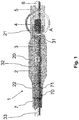
- the present invention relates to a balloon catheter 1 and a method for producing such a balloon catheter.
- the balloon catheter 1 has according to the in the Figure 1 Embodiment shown on a balloon 2, which surrounds a balloon interior 20 and has a proximal and a distal end portion 22, 21.
- a stent not shown, can be crimped onto the balloon 2.
- the stent can be a drug-coated stent.
- the balloon catheter 1 is used for implanting and fixing the stent on the wall of a patient's vessel (for example in the case of angioplasty).
- the balloon catheter 1 further preferably has an outer shaft 7 which surrounds a lumen 70, a proximal section 33 of the inner shaft 3 of the catheter 1 being arranged in the lumen 70 of the outer shaft 7 and a distal end section 71 of the outer shaft 7 from the lumen 70 of the outer shaft 7 is led out, so that a further section 32 of the inner shaft 3 in the balloon interior 20 extends to a distal end section 31 of the inner shaft 3.
- the balloon 2 is connected in particular via the proximal end section 22 of the balloon 2 to the distal end section 71 of the outer shaft 7. Furthermore, the balloon 2 is connected, in particular welded, to the distal end section 31 of the inner shaft 3 via its distal end section 21.
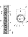
- the section 32 of the inner shaft 3 arranged in the balloon interior 20 and in particular the proximal section 33 have a plurality of superimposed and connected to each other Have material layers 3a, 3b, 3c, which surround a lumen 30 of the inner shaft 3.
- the inner shaft 3 has, for example in sections 32 and 33, a three-layer wall.
- the outermost material layer 3a can consist of polyamide.
- the innermost material layer 3c preferably consists of HDPE and the middle material layer 3b preferably consists of a polyethylene adhesive such as LLDPE.
- the inner diameter D1 of the inner shaft 3 can be, for example, 0.42 mm.
- the outer diameter D2 can be 0.57 mm.
- the innermost and middle material layers 3c, 3b can furthermore have a thickness W of 0.023 mm (cf. Fig. 3 ).
- the invention provides that the distal end section 31 of the inner shaft 3, which is to be welded to the distal end section 21 of the balloon 2, is produced in one layer.
- the distal end section 31 of the inner shaft 3 preferably consists of only one layer (3a) PA 12.
- this can e.g. processed over a length of 5 mm to 10 mm so that only the outermost material layer 3a remains there, for example by drilling, machining or laser ablation.
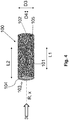
- the device 100 has a tool 101, which in the present case is, for example, a drill or a reamer, which is used to remove the material layers 3b, 3c by machining is configured.
- the tool 100 has a length L1 in the direction of the axis of rotation R (for example 5 mm), which corresponds to the length of the material layers 3b, 3c to be removed.
- the tool 101 is rotated to remove the material layers 3b, 3c by means of a rotary motor 102, the axis of rotation R being aligned such that it coincides with the longitudinal axis x of the catheter 1 or inner shaft 3. Furthermore, the tool 101 is arranged in a nozzle 103 aligned coaxially to the tool 101, which serves to guide the distal end section 31 of the inner shaft when removing the material layers 3b, 3c.
- the distal end section 31 of the inner shaft 3 is positively inserted into the nozzle 103 via a nozzle opening 104, the rotating tool 101 penetrating into the distal end section 31 and removing the two inner material layers 3b, 3c there.
- the nozzle 103 has a length L2 for guiding the inner shaft 3 in the direction of the axis of rotation R, which length is preferably greater than or equal to L1.
- the diameter D4 of the drill 101 is e.g. 0.47 mm with a length L1 of e.g. 5 mm and the inner diameter D3 of the nozzle 103 is e.g. 0.575 mm with a length L2 of e.g. 10 mm.
- the particles or chips formed during the removal of the inner layers 3b, 3c can be suctioned off with a particle acid 105 of the device 100, which is in flow connection with the nozzle 103.
- This device also provides cooling for the drill.
- the latter can be safely welded to the distal end section 21 of the balloon 2 by means of a laser.
- the distal end section 21 of the balloon 2 can be shrunk by means of a shrink tube 5, which in the Figure 1 is shown to be fixed on the distal end section 31 of the inner shaft 3.
- the invention advantageously prevents delamination in the area of the welded connection between the distal end sections 21, 31 of the balloon 2 and the inner shaft 3, thereby reducing the risk of a guide wire 6, which is guided in the lumen 30 of the inner shaft 3, becoming blocked. On the process side, higher productivity and a lower reject rate are also achieved.
Landscapes
- Health & Medical Sciences (AREA)
- Life Sciences & Earth Sciences (AREA)
- Heart & Thoracic Surgery (AREA)
- Biomedical Technology (AREA)
- Animal Behavior & Ethology (AREA)
- Pulmonology (AREA)
- Engineering & Computer Science (AREA)
- Anesthesiology (AREA)
- Veterinary Medicine (AREA)
- Hematology (AREA)
- Biophysics (AREA)
- General Health & Medical Sciences (AREA)
- Public Health (AREA)
- Child & Adolescent Psychology (AREA)
- Vascular Medicine (AREA)
- Media Introduction/Drainage Providing Device (AREA)
- Materials For Medical Uses (AREA)
Priority Applications (1)
| Application Number | Priority Date | Filing Date | Title |
|---|---|---|---|
| EP18213575.6A EP3669926A1 (fr) | 2018-12-18 | 2018-12-18 | Cathéter à ballonnet ainsi que procédé et dispositif de fabrication du cathéter à ballonnet |
Applications Claiming Priority (1)
| Application Number | Priority Date | Filing Date | Title |
|---|---|---|---|
| EP18213575.6A EP3669926A1 (fr) | 2018-12-18 | 2018-12-18 | Cathéter à ballonnet ainsi que procédé et dispositif de fabrication du cathéter à ballonnet |
Publications (1)
| Publication Number | Publication Date |
|---|---|
| EP3669926A1 true EP3669926A1 (fr) | 2020-06-24 |
Family
ID=64745896
Family Applications (1)
| Application Number | Title | Priority Date | Filing Date |
|---|---|---|---|
| EP18213575.6A Withdrawn EP3669926A1 (fr) | 2018-12-18 | 2018-12-18 | Cathéter à ballonnet ainsi que procédé et dispositif de fabrication du cathéter à ballonnet |
Country Status (1)
| Country | Link |
|---|---|
| EP (1) | EP3669926A1 (fr) |
Citations (5)
| Publication number | Priority date | Publication date | Assignee | Title |
|---|---|---|---|---|
| EP0953363A1 (fr) * | 1998-05-01 | 1999-11-03 | Smiths Industries Public Limited Company | Tuyaux médico-chirurgicaux et méthodes de fabrication |
| WO2013146306A1 (fr) * | 2012-03-28 | 2013-10-03 | テルモ・クリニカルサプライ株式会社 | Cathéter à ballon pour obturation de vaisseau sanguin |
| US20140276400A1 (en) * | 2013-03-15 | 2014-09-18 | Abbott Cardiovascular Systems Inc. | Reduced Material Tip for Catheter and Method of Forming Same |
| WO2016098670A1 (fr) * | 2014-12-15 | 2016-06-23 | テルモ株式会社 | Cathéter à ballonnet |
| EP3243547A1 (fr) * | 2016-05-12 | 2017-11-15 | Biotronik AG | Cathéter à ballonnet comprenant un marqueur visible aux rayons x |
-
2018
- 2018-12-18 EP EP18213575.6A patent/EP3669926A1/fr not_active Withdrawn
Patent Citations (5)
| Publication number | Priority date | Publication date | Assignee | Title |
|---|---|---|---|---|
| EP0953363A1 (fr) * | 1998-05-01 | 1999-11-03 | Smiths Industries Public Limited Company | Tuyaux médico-chirurgicaux et méthodes de fabrication |
| WO2013146306A1 (fr) * | 2012-03-28 | 2013-10-03 | テルモ・クリニカルサプライ株式会社 | Cathéter à ballon pour obturation de vaisseau sanguin |
| US20140276400A1 (en) * | 2013-03-15 | 2014-09-18 | Abbott Cardiovascular Systems Inc. | Reduced Material Tip for Catheter and Method of Forming Same |
| WO2016098670A1 (fr) * | 2014-12-15 | 2016-06-23 | テルモ株式会社 | Cathéter à ballonnet |
| EP3243547A1 (fr) * | 2016-05-12 | 2017-11-15 | Biotronik AG | Cathéter à ballonnet comprenant un marqueur visible aux rayons x |
Non-Patent Citations (13)
| Title |
|---|
| CHEMICAL ABSTRACTS, Columbus, Ohio, US; abstract no. 24937-16-4 |
| CHEMICAL ABSTRACTS, Columbus, Ohio, US; abstract no. 24937-78-8 |
| CHEMICAL ABSTRACTS, Columbus, Ohio, US; abstract no. 25035-04-5 |
| CHEMICAL ABSTRACTS, Columbus, Ohio, US; abstract no. 25038-54-4 |
| CHEMICAL ABSTRACTS, Columbus, Ohio, US; abstract no. 25038-59-9 |
| CHEMICAL ABSTRACTS, Columbus, Ohio, US; abstract no. 26098-55-5 |
| CHEMICAL ABSTRACTS, Columbus, Ohio, US; abstract no. 32131-17-2 |
| CHEMICAL ABSTRACTS, Columbus, Ohio, US; abstract no. 3319-31-1 |
| CHEMICAL ABSTRACTS, Columbus, Ohio, US; abstract no. 75701-44-9 |
| CHEMICAL ABSTRACTS, Columbus, Ohio, US; abstract no. 77402-38-1 |
| CHEMICAL ABSTRACTS, Columbus, Ohio, US; abstract no. 9002-84-0 |
| CHEMICAL ABSTRACTS, Columbus, Ohio, US; abstract no. 9002-88-4 |
| CHEMICAL ABSTRACTS, Columbus, Ohio, US; abstract no. 9011-52-3 |
Similar Documents
| Publication | Publication Date | Title |
|---|---|---|
| DE60311477T2 (de) | Vertikales Stentschneidesystem | |
| DE69912718T2 (de) | Katheter zur rheolytischen Thrombektomie | |
| DE69531949T2 (de) | Katheter zur medikamentenzuführung und dilatationskatheter mit medikamentenzuführung welche schnell ausgetaucht werden können | |
| DE69830444T2 (de) | Dreilagig extrudierter medizinischer Schlauch und medizinische Vorrichtungen mit diesem Schlauch | |
| DE69625329T3 (de) | Eingriffkatheter | |
| DE69002295T2 (de) | Mehrschichtextrusion als verfahren zur herstellung von ballons zur gefaessplastik. | |
| DE69533578T2 (de) | Mehrlumiger katheter | |
| DE69230377T2 (de) | Laserschweissen von angioplastie ballonkathetern | |
| DE69503498T2 (de) | Befestigung einer weichen spitze für dünnwandige katheter | |
| DE69217928T2 (de) | Koextrudierte, medizinische ballone sowie katheter mit solchen ballonen | |
| DE69918244T2 (de) | Führungskatheter mit weicher Spitze | |
| DE60011722T2 (de) | Verstärkter Ballonkatheter | |
| DE60017752T2 (de) | Katheter mit einer durchgehenden verstärkung aus gewickeltem draht | |
| DE60307988T2 (de) | Medizinisches gerät | |
| DE602005004628T2 (de) | Katheter mit einem expandierbaren Körper | |
| DE60225147T2 (de) | Ballonkatheter und verfahren zu seiner stabilisierung bei der dehnung | |
| DE69937235T2 (de) | Ballon mit weicher, flexibler distaler extremität | |
| DE202006020982U1 (de) | Katheter mit einer weichen distalen Spitze | |
| DE69401007T2 (de) | Aus Katheter und Hülse bestehende Einheit | |
| DE69714582T2 (de) | Katheter zur lokalen verabreichung einer therapeutisch aktiven substanz | |
| DE60209803T2 (de) | Katheter mit einem verbesserten das drehmoment übertragenden schaft | |
| EP0021446A1 (fr) | Cathéter court, séparable et en matière plastique | |
| EP2184081A1 (fr) | Arbre de cathéter | |
| DE102012110253A1 (de) | Medizinische Fräse mit Absaugung | |
| DE60209382T2 (de) | Strukturiertes material für den distalen ballonbund und verfahren zu seiner herstellung |
Legal Events
| Date | Code | Title | Description |
|---|---|---|---|
| PUAI | Public reference made under article 153(3) epc to a published international application that has entered the european phase |
Free format text: ORIGINAL CODE: 0009012 |
|
| STAA | Information on the status of an ep patent application or granted ep patent |
Free format text: STATUS: THE APPLICATION HAS BEEN PUBLISHED |
|
| AK | Designated contracting states |
Kind code of ref document: A1 Designated state(s): AL AT BE BG CH CY CZ DE DK EE ES FI FR GB GR HR HU IE IS IT LI LT LU LV MC MK MT NL NO PL PT RO RS SE SI SK SM TR |
|
| AX | Request for extension of the european patent |
Extension state: BA ME |
|
| STAA | Information on the status of an ep patent application or granted ep patent |
Free format text: STATUS: THE APPLICATION IS DEEMED TO BE WITHDRAWN |
|
| 18D | Application deemed to be withdrawn |
Effective date: 20210112 |