EP3670000B1 - Befestigungssystem für die montage einer abgabepumpe auf einem flakon, und entsprechender flakon eines flüssigen produkts - Google Patents
Befestigungssystem für die montage einer abgabepumpe auf einem flakon, und entsprechender flakon eines flüssigen produkts Download PDFInfo
- Publication number
- EP3670000B1 EP3670000B1 EP19214620.7A EP19214620A EP3670000B1 EP 3670000 B1 EP3670000 B1 EP 3670000B1 EP 19214620 A EP19214620 A EP 19214620A EP 3670000 B1 EP3670000 B1 EP 3670000B1
- Authority
- EP
- European Patent Office
- Prior art keywords
- collar
- travel
- attachment system
- sleeve
- hinge collar
- Prior art date
- Legal status (The legal status is an assumption and is not a legal conclusion. Google has not performed a legal analysis and makes no representation as to the accuracy of the status listed.)
- Active
Links
Images


Classifications
-
- B—PERFORMING OPERATIONS; TRANSPORTING
- B05—SPRAYING OR ATOMISING IN GENERAL; APPLYING FLUENT MATERIALS TO SURFACES, IN GENERAL
- B05B—SPRAYING APPARATUS; ATOMISING APPARATUS; NOZZLES
- B05B11/00—Single-unit hand-held apparatus in which flow of contents is produced by the muscular force of the operator at the moment of use
- B05B11/0005—Components or details
- B05B11/0008—Sealing or attachment arrangements between sprayer and container
-
- B—PERFORMING OPERATIONS; TRANSPORTING
- B05—SPRAYING OR ATOMISING IN GENERAL; APPLYING FLUENT MATERIALS TO SURFACES, IN GENERAL
- B05B—SPRAYING APPARATUS; ATOMISING APPARATUS; NOZZLES
- B05B11/00—Single-unit hand-held apparatus in which flow of contents is produced by the muscular force of the operator at the moment of use
- B05B11/01—Single-unit hand-held apparatus in which flow of contents is produced by the muscular force of the operator at the moment of use characterised by the means producing the flow
- B05B11/10—Pump arrangements for transferring the contents from the container to a pump chamber by a sucking effect and forcing the contents out through the dispensing nozzle
-
- B—PERFORMING OPERATIONS; TRANSPORTING
- B05—SPRAYING OR ATOMISING IN GENERAL; APPLYING FLUENT MATERIALS TO SURFACES, IN GENERAL
- B05B—SPRAYING APPARATUS; ATOMISING APPARATUS; NOZZLES
- B05B11/00—Single-unit hand-held apparatus in which flow of contents is produced by the muscular force of the operator at the moment of use
- B05B11/01—Single-unit hand-held apparatus in which flow of contents is produced by the muscular force of the operator at the moment of use characterised by the means producing the flow
- B05B11/10—Pump arrangements for transferring the contents from the container to a pump chamber by a sucking effect and forcing the contents out through the dispensing nozzle
- B05B11/1042—Components or details
- B05B11/1043—Sealing or attachment arrangements between pump and container
- B05B11/1045—Sealing or attachment arrangements between pump and container the pump being preassembled as an independent unit before being mounted on the container
-
- B—PERFORMING OPERATIONS; TRANSPORTING
- B05—SPRAYING OR ATOMISING IN GENERAL; APPLYING FLUENT MATERIALS TO SURFACES, IN GENERAL
- B05B—SPRAYING APPARATUS; ATOMISING APPARATUS; NOZZLES
- B05B11/00—Single-unit hand-held apparatus in which flow of contents is produced by the muscular force of the operator at the moment of use
- B05B11/01—Single-unit hand-held apparatus in which flow of contents is produced by the muscular force of the operator at the moment of use characterised by the means producing the flow
- B05B11/10—Pump arrangements for transferring the contents from the container to a pump chamber by a sucking effect and forcing the contents out through the dispensing nozzle
- B05B11/1042—Components or details
- B05B11/1043—Sealing or attachment arrangements between pump and container
- B05B11/1049—Attachment arrangements comprising a deformable or resilient ferrule clamped or locked onto the neck of the container by displacing, e.g. sliding, a sleeve surrounding the ferrule
Definitions
- the invention relates to a system for fixing a fluid dispenser pump.
- the invention also relates to the bottle of associated fluid product.
- the fluid product can be a cosmetic product, a pharmaceutical product or any other product.
- Bottles of fluid product conventionally comprise a reservoir for the fluid product surmounted in its upper part by a rigid neck defining an opening into which the fluid product dispensing system is inserted.
- the dispensing system comprises a pump which can be actuated by a user by means of a push button, which makes it possible to dispense a dose of the fluid product, in particular in the form of a spray.
- the dispensing system further comprises fastening and sealing means which allow it to be held at the level of the neck and, if necessary, to isolate the reservoir from the external environment.
- fastening means allowing permanent fastening of the dispensing system at the level of the neck, fastening means requiring a threshold force to unlock said fastening means and removable fastening means.
- the use of one configuration rather than another depends on the problem addressed.
- the fastening system is provided with a sleeve, a collar mounted around the sleeve and able to move partially according to a helical movement around said sleeve by the actuation of a hoop.
- the sleeve is configured so that the unscrewing the fastening system requires the application of a threshold force by the user, thanks to the presence of lugs.
- This fixing system is characterized in that said start and end of stroke positions are located so that the joint collar is able to pass from the high position of dismantling to the low position of use by translation.
- the idea of the invention is to allow the reassembly of the pump by a simple gesture, namely, a translation while retaining the advantages of a fixing system comprising a sleeve, an articulation collar and a hoop.
- the start and end of travel positions are advantageously located in axial extension of each other so that the joint collar is able to slide from the end of travel housing towards the start housing stroke by translation and that the reassembly of the pump is also possible by simple support of the user.
- the system is again in the starting position of the race and the same disassembly/reassembly cycle can be started again.
- the invention further relates to a dispensing bottle for a fluid product, comprising a reservoir for the fluid product, said reservoir being provided with a neck defining an opening for said reservoir, said bottle further comprising a dispensing pump and a system fixing as described above, said system making it possible to fix said pump on said neck.
- said neck of the dispensing bottle is provided with an anti-rotation system of said fixing system.
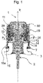
- the invention relates to a dispensing bottle for a fluid product comprising a reservoir 3 and a dispensing head 1 for the fluid product contained in the reservoir 3.
- the fluid product can be a cosmetic product, a pharmaceutical product or any other product which can usefully be stored in a bottle.
- the fluid can be directly in contact with the reservoir 3. That said, the fluid can be included in a flexible pocket located within said reservoir 3 so that it is not in contact with the reservoir 3 but with said flexible pocket .
- Reservoir 3 can be either rigid or deformable. This being so, the reservoir 3 comprises, at an upper part, a neck 4 and an opening 5 formed in said neck 4.
- the neck 4 is preferably rigid. It forms a groove 7 with the reservoir 3 and a peripheral edge 6 surmounting said groove 7.
- the dispensing head 1 is equipped with a pump 2 for dispensing the fluid product contained in the reservoir 3.
- the dispensed fluid is in particular liquid, viscous or pasty.
- the dispensing pump 2 comprises a body extending along a central longitudinal axis X corresponding to a median axis of the bottle.
- the body is of tubular shape, in particular of revolution.
- the dispensing pump 2 is held stationary at the level of the neck 4 by means of a fastening system according to the invention. This being the case, the distribution pump 2 can be removed from this location by means of said fixing system, for example for the purpose of filling the reservoir 3. In other words, the distribution pump 2 is removable.
- the fixing system comprises a fixing sleeve 10, an articulation collar 25 and a hoop 30.
- the articulation collar 25 and the sleeve 10 are mounted so as to move relative to each other between a start of stroke position P I (illustrated in figure 1 ) and a limit position P F (shown in picture 3 ).
- the kinematics of movement of said joint collar 25 relative to said sleeve 10 will be better described below.
- the hoop 30 is itself configured to actuate a displacement of said articulation collar 25 relative to said sleeve 10. It also has a decorative function, its outer surface being visible to the user.
- the sleeve 10 is of generally cylindrical shape and extends along the axis X.
- the sleeve 10 is hollow. It delimits an empty interior volume essentially serving to accommodate the dispensing pump 2. However, the pump 2 extends axially beyond the ends of the sleeve 10.
- the sleeve 10 is provided with means 11 for attaching the dispensing pump 2.
- the hooking means 11 make it possible to keep the pump 2 immobile at the level of the neck 4, for example in an extended way thanks to a seal 9.
- the sleeve 10 comprises a skirt 12 configured to come into engagement with the neck 4.
- the skirt 12 comprises a flat portion 14 capable of coming around the peripheral edge 6, possibly by tightening.
- the skirt 12 further comprises fastening means 15 to the neck 4 extending in the extension of the flat portion 14.
- the fixing means 15 consist of flexible lugs able to perform movements independently of each other.
- the flexible tabs 15 are regularly spaced from each other over the entire periphery of the skirt 12, that is to say that the flexible tabs are separated from each other by a constant distance.
- the flexible tabs 15 are connected to the flat portion 14 by means of a hinge portion 15a. They alternately adopt a release position in which they are free, that is to say they are not in engagement with the neck 4 and an engagement position in which they are in engagement with said neck 4.
- flexible tabs 15 have, on their internal faces, that is to say on their faces facing the neck 4, a shape substantially complementary to the shape of the groove 7. In the configuration illustrated in figure 1 , the flexible lugs 15 are in the released position, that is to say they are not engaged in the groove 7.
- the sleeve 10 further comprises a guide collar 16 whose main function is to guide the joint collar 25 in its movements.
- the articulation collar 25 is more precisely mounted mobile around the guide collar 16. In other words, it is capable of moving relative to said guide collar 16.
- Said guide collar 16 comprises means for guiding said collar hinge 25, which will be described in more detail below.
- the articulation collar 25, for its part, comprises means for moving along said guide means of said guide collar 16.
- the guide collar 16 and the articulation collar 25 therefore form a movable mechanical assembly.
- the guide collar 16 is located in the longitudinal extension of the skirt 12.
- the hoop 30 is generally cylindrical in shape. As mentioned above, it is configured to actuate the movement of said joint collar 25. In this respect, it comprises an inner wall 31 on which ribs 32 are angularly distributed. The ribs are more precisely located on an upper portion of the hoop 30, along which the joint collar 25 is able to move. The ribs 32 make it possible to secure the hoop 30 and the articulation collar 25. In this case, in the embodiment illustrated in figures 1 to 3 , it can be seen that the ribs 32 (visible on the figure 1 ) are embedded in an outer wall 29 of the articulation collar 25, which allows the tightening and therefore the securing of the hoop 30 around the articulation collar 25. This thus makes it possible to make the drive of the articulation collar 25 more reliable. by fret 30.
- hoop 30 is configured to perform a translational movement. This translation movement of the hoop 30 is made possible by the configuration of the hinge collar 25 relative to the skirt 12.
- the outer wall 29 of the hinge collar 25 is here substantially aligned with the flat portion 14 of the skirt 12 so that hoop 30 is always held in abutment on outer wall 29 and on flat portion 14.
- hoop 30 is thus capable of moving longitudinally, in particular between a proximal position and a distal position relative to the sleeve 10 by driving said articulation collar 25.
- hoop 30 is adapted to actuate the movement of joint collar 25 between a high position P H for dismantling and a low position P B for use.
- the hoop 30 must move towards its distal position.
- the hoop 30 must move towards its proximal position. It should be noted that in the configuration illustrated in the figure 1 , the joint collar 25 is neither in the high position P H for dismantling nor in the low position P B for use but in a position before initial assembly.
- the joint collar 25 is in the low position P B of use.
- the fixing system is held rigidly around the collar 4 and the bottle is ready to be used.
- the hoop 30 being located in the proximal position and therefore completely lowered, its inner wall 31 exerts a radial pressure on the fixing means 15 which are in the engagement position.
- the fixing means 15 are engaged with the neck 4.
- the outer faces of the flexible tabs 15 are in vertical alignment with the flat portion 14, while their inner faces are completely engaged in the groove 7 of the collar.
- the groove 7 includes a recess 8.
- the recess 8 forms an anti-rotation system of the fixing system in which one or more lugs 15 can be housed.
- the joint collar 25 is in the high dismantling position P H.
- the fastening system is no longer in engagement with the collar 4.
- the user may possibly fill the reservoir 3 again if the fluid product used lends itself to such manipulation.
- the hoop 30 being located in the distal position, and therefore fully raised, the inner wall 31 no longer exerts pressure on the fixing means 15 which releases said fixing means 15.
- the flexible tabs 15 are in the release position. In other words, the flexible tabs 15 are free.
- the figure 1 illustrates the bottle before initial fixing of the dispensing head 1 on the reservoir. Such an operation takes place, for example, at the manufacturer in charge of the initial filling of the bottle.
- the sleeve 10 is mounted on the neck 4, the flexible tabs 15 being free.
- the joint collar 25 is in the low position P B of use.
- the hoop 30 is in a retracted position corresponding to the high position P H for dismantling the picture 3 but without the hoop already being tightly mounted on said hinge collar 25, thus allowing the flexible tabs 15 to be free and the dispensing head 1 to be mounted on the reservoir.
- the hoop 30 is lowered by force according to a translational movement and the dispensing head passes into the configuration of the picture 2 .
- This translation movement is facilitated by the ribs 32 dedicated to guiding the joint collar 25.
- the joint collar 25 when the joint collar 25 is located in the high dismantling position P H ( fig. 3 ), it is in abutment with the sleeve 10 at an end position P F .
- the joint collar 25 when the joint collar 25 is located in the low position P B of use ( fig. 2 ), it is in abutment with said sleeve 10 at the start of stroke position P I .
- the devices of the prior art are configured so that the user is obliged to unscrew the joint collar 25 from the sleeve 10. The subsequent reassembly, if permitted, is then carried out by screwing.
- joint collar 25 and the sleeve 10 can be in abutment, without necessarily that one of said parts is embedded in the other part. In other words, there may be play between joint collar 25 and sleeve 10.
- the start and end positions P I , P F are located so that the articulation collar 25 is able to pass from the high position P H of dismantling (as illustrated in figure 2 ) to the low operating position P B (as illustrated in picture 3 ) by translation.
- the fastening system can be dismantled, for example, by unscrewing, said fastening system can be reassembled on the neck 4 of the tank 3 by a simple translational movement and therefore a simple support from the user. No screwing is therefore necessary for reassembly.
- the sleeve 10 advantageously comprises first means for guiding, in translation, said articulation collar 25 of the high position P H for disassembly to the low position P B for use.
- the first means for guiding in translation are located on the guide collar 16. They extend along the start of stroke position P I and the end of stroke position P F . It is preferable that these first means for guiding in translation be at least two in number. This makes it possible to make the movement of the articulation collar 25 relative to the sleeve 10 more reliable.
- these first means for guiding in translation comprise a start-of-stroke housing 19 located at the start-of-stroke position P I and an end-of-stroke housing 20 located at the end-of-stroke position P F .
- the start and end of travel housings 19, 20 form, in combination, a groove or even a notch having a grip of substantially rectangular shape on the guide collar 16.
- the groove extends longitudinally over the entire height of the guide collar 16, that is to say between an upper free edge of the guide collar 16 and the skirt 12.
- the height of the guide collar 16 therefore corresponds substantially to the longitudinal distance that the articulation collar 25 can cover during its travel from the high position P H for disassembly to the low position P B for use.
- the skirt 12 forms an outer bearing surface 13 on which rests a lower edge of the joint collar 25 when it is in the low position P B of use.
- the outer bearing surface 13 contributes to the blocking in translation of the articulation collar 25.
- the limit switch housing 20 comprises a flat end 20a forming a discontinuity at the level of the upper free edge of the guide collar 16. This in particular makes it possible to predispose the articulation collar 25 with respect to the guide collar 16 and the initial mounting of the articulation collar on the sleeve 10.
- Each of said first means for guiding in translation further comprises a first locking means 18.
- the start and end of travel housings 19, 20 are connected via said first locking means 18. Any translational movement of the collar d articulation 25 from the high position P H for disassembly to the low position P B for use implies that said articulation collar 25 is able to pass over said first locking means 18.
- Said first locking means 18 is configured to allow said joint collar 25 to move in translation from the high position P H for dismantling to the low position P B for use by translation by application of a threshold pressure.
- said first locking means 18 forms a boss, that is to say an extra thickness between said start and end of travel housings 19, 20.
- the first locking means 18 comprises a retaining portion 18a.
- Said retaining portion 18a forms a bearing surface for the articulation collar 25 when the latter is in the high dismantling position P H.
- the retaining portion 18a is inclined with respect to a bottom of the groove. More precisely, it makes an obtuse angle with the limit switch housing 20. Being thus configured, the retaining portion 18a allows both the maintenance of the articulation collar 25 and its sliding along the groove, and therefore from the end-of-travel position P F towards the start-of-travel position P I .
- said first locking means 18 comprises a locking flange 18b.
- This locking rim 18b extends from the bottom of the groove along a plane transverse to the axis direction X. More precisely, it forms a right angle with the start of travel housing 19.
- the locking rim 18b therefore forms an upper stop for said joint collar 25 in the low position P B of use.
- the first locking means 18 comprises a ridge 18c by which the retaining portion 18a is connected to the locking flange 18b.
- the edge 18c can be likened to a top of the boss 18.
- the ridge 18c has a height, referred to as the projection height, substantially equal to the depth of the groove relative to an outer periphery of the guide collar 16. This is not mandatory.
- the projection height defines the pressure which must be applied to the joint collar 25 to cross the first locking means 18 and reach the start-of-stroke housing 19. It is understood that the higher the projection height, the greater the pressure at exercise is important.
- the joint collar 25 is in the form of a hollow cylinder. This is not limiting in the context of the present invention. In any case, it is necessary that the shape of the joint collar 25 conforms to that of the sleeve 10 since the joint collar 25 is movably mounted around said sleeve 10.
- the joint collar 25 comprises a protuberance 26 able to move along said first translational guide means. Protrusion 26 extends radially from an inner wall of joint collar 25. It has a generally rectangular shape, although this is not required. This shape is adapted to that of the guide means along which it must move. More specifically, longitudinally oriented lateral sides of the protuberance 26 slide against longitudinally oriented lateral sides of the groove formed by the housings 19, 20.
- the outer collar 25 also has an inner bead 27 able to bear against an extra thickness 17 of an upper edge of the sleeve 10.
- the joint collar 25 is in the high dismantling position P H , it is configured to remain at the level of the end-of-travel position 20, so that the articulation collar 25 is maintained at the level of the sleeve 10.
- a lower edge said articulation collar is capable of coming to rest on the outer bearing surface 13.
- the sleeve 10 may comprise, in addition to the first means for guiding in translation, second means for guiding the articulation collar 25. These second guide means allow the articulation collar 25 to be screwed and unscrewed from said sleeve 10.
- these second guiding means are positioned on the guide collar 16. Preferably, they extend between said start and end positions P I , P F . Each has at its ends a start of travel housing 19 and an end of travel housing 20. It should be understood that if there are two second guide means this implies that there are four housings in total since each of the second guide means comprises a start of race housing 19 and an end of race housing 20, in the longitudinal sequence of one another, two by two.
- the fastening system according to the invention is particularly ingenious. Indeed, the start and end of travel housings 19, 20 referred to in the second guide means are the same housings which form the first translation guide means, in this case the groove.
- the architecture of the guide means is thus optimized to allow both the reassembly of the fastening system by simple pressing of the user but also the screwing and unscrewing of said system.
- the second guide means are configured so that the articulation collar 25 is able to perform a rotational and translational movement, in particular screwing around said sleeve 10 in order to dismantle the fastening system.
- each of the second guide means advantageously comprises a helical section 21.
- Each helical section 21 comprises a first end 22 comprising the start-of-travel housing 19 and a second end 23 comprising the end-of-travel housing 20.
- the number of second guide means is preferably at least equal to two. That said, this number is not limiting.
- second guide means each comprising a helical section 21 1 , ..., 21 i , 21 i+1 ,..., 21 n , i being a natural number with i ⁇ 1 and i+1 ⁇ n.
- Each of the helical sections 21 1 , ..., 21 i , 21 i+1 ,..., 21 n , i being a natural integer with i ⁇ n respectively comprises a first end 22 1 , ..., 22 i , 22 i+1 ,..., 22 n and a second end 23 1 , ..., 23 i , 23 i+1 ,..., 23 n .
- Said second guide means are configured so that the first end 22 1 of a first helical section 21 1 is located opposite the second end 23 n of a last helical section 21 n and that each of the other first ends 22 i+1 of the helical sections is located opposite the other second ends 23 i of the helical sections which precede them.
- the first ends 22 1 , ..., 22 i , 22 i+1 ,..., 22 n form with the second ends 23 1 , ..., 23 i , 23 i+1 ,... , 23 n the housings of the first means for guiding in translation, in this case grooves, which makes the fastening system of the invention a system that is both practical and ingenious.
- n is equal to one
- the ends of the helical section 21 also form the start and end housings. end of race 19, 20 of the groove allowing the joint collar 25 to pass from the high position P H for dismantling to the low position P B for use.
- first helical section 21 1 makes a half turn of the guide collar 16 and the second helical section 21 2 makes a remaining half turn of the guide collar 16.
- first end 22 1 of the first helical section 21 1 is located opposite the second end 23 2 of the second helical section 21 2 and the first end 22 2 of the second helical section 22 5 is located opposite -à-vis the second end 23 1 of the first helical section.
- the first end 22 1 and the second end 23 2 form the housings of a first means of guiding in translation, while the first end 22 2 and the second end 23 1 form the housings of a second means of guiding in translation.
- each second guide means comprises second locking means 19b, 20b separating the start and end of travel housings 19, 20 of said helical section 21.
- Said second locking means 19b, 20b consist of bosses or extra thicknesses, one of which projection height determines the pressure which must be applied so that the articulation collar 25, in particular the protuberance 26 leaves the start or end of stroke housing 19, 20 to reach the helical section 21.
- the second locking means 19b, 20b are configured to allow rotational movement of the joint collar 25 around said sleeve 10 by applying a threshold pressure.
- the extra thickness 20b forms a firm abutment (as illustrated in the figure 4b ). In other words, it prevents the screwing of the joint collar 25 around the sleeve 10, even if high pressure is exerted. In such a configuration, the protrusion 26 cannot leave the end-of-travel housing 20 to reach the helical section 21. It is thus understood that only the translation of the protrusion 26 from the end-of-travel housing 20 towards the start of race 19 is authorized to reach the low position P B of use.
- the extra thickness 20b is configured so that the unscrewing of the articulation collar 25 around the sleeve 10 is authorized by application of a threshold pressure (as illustrated on the figure 4b ).
- the protrusion 26 moves from the end-of-travel housing 20 towards the start-of-travel housing 19 passing over the extra thickness 20b, along the helical section 21 and over the extra thickness 19b, in this order it is of a screw.
- the joint collar 25 therefore passes from the high position P H for dismantling to the low position for use P B by screwing.
Landscapes
- Containers And Packaging Bodies Having A Special Means To Remove Contents (AREA)
- Closures For Containers (AREA)
Claims (15)
- System zum Befestigen einer Abgabepumpe (2) an dem Hals (4) eines Behälters, der ein flüssiges Produkt enthält, wobei das System umfasst:- eine Muffe (10), die Mittel zum Befestigen (15) an dem Hals (4) und Mittel zum Aufhängen (11) der Pumpe (2) umfasst;- eine Gelenkmanschette (25), wobei die Gelenkmanschette (25) und die Muffe (10) in Bezug aufeinander beweglich zwischen einer Hubendposition (PF) und einer Hubanfangsposition (PI) montiert sind;- einen Ring (30), der dazu ausgelegt ist, die Gelenkmanschette (25) zwischen einer hohen Position (PH) der Zerlegung, in der die Befestigungsmittel ungebunden sind, und einer niedrigen Position (PB) der Verwendung, in der die Befestigungsmittel den Hals (4) rundum in Eingriff nehmen, zu verschieben; wobei das Befestigungssystem dadurch gekennzeichnet ist, dass die Hubanfangs- und -endpositionen (PI, PF) derart gelegen sind, dass die Gelenkmanschette (25) imstande ist, durch Translation von der hohen Position (PH) der Zerlegung zur niedrigen Position (PB) der Verwendung überzugehen.
- Befestigungssystem nach Anspruch 1, wobei die Muffe (10) erste Mittel zum translatorischen Führen der Gelenkmanschette (25) von der hohen Position (PH) der Zerlegung zur niedrigen Position (PB) der Verwendung umfasst.
- Befestigungssystem nach Anspruch 2, wobei die ersten Mittel zum translatorischen Führen eine Hubanfangsaufnahme (19), die an der Hubanfangsposition (PI) gelegen ist, und eine Hubendaufnahme (20), die an der Hubendposition (PF) gelegen ist, umfassen, wobei die Hubanfangs- und -endaufnahmen (19, 20) in der Verlängerung zueinander gelegen sind.
- Befestigungssystem nach Anspruch 3, wobei die ersten Mittel zum translatorischen Führen ein erstes Verriegelungsmittel (18) umfassen, wobei die Hubanfangs- und - endaufnahmen (19, 20) durch das erste Verriegelungsmittel (18) getrennt sind, wobei das erste Verriegelungsmittel (18) dazu ausgelegt ist, die translatorische Verschiebung der Gelenkmanschette (25) von der hohen Position (PH) der Zerlegung zur niedrigen Position (PB) der Verwendung durch Anwendung eines Schwellendrucks zu erlauben.
- Befestigungssystem nach Anspruch 4, wobei das erste Verriegelungsmittel (18) eine Erhöhung bildet.
- Befestigungssystem nach einem der Ansprüche 4 bis 5, wobei das erste Verriegelungsmittel (18) einen Abschnitt zum Halten (18a) der Gelenkmanschette (25) in der hohen Position (PH) der Zerlegung umfasst, wobei der Halteabschnitt (18a) in der Verlängerung der Hubendaufnahme (20) gelegen ist.
- Befestigungssystem nach einem der Ansprüche 4 bis 6, wobei das erste Verriegelungsmittel (18) eine Kante zum Verriegeln (18b) der Gelenkmanschette (25) in der niedrigen Position (PB) der Verwendung umfasst, wobei die Verriegelungskante einen Anschlag für die Gelenkmanschette (25) in der Hubanfangsaufnahme (19) bildet.
- Befestigungssystem nach einem der Ansprüche 1 bis 7, wobei die Muffe (10) weiter zweite Mittel zum Führen der Gelenkmanschette (25) umfasst, die an ihren Enden die Hubanfangs- und -endposition (PI, PF) umfassen.
- Befestigungssystem nach Anspruch 8, in seiner Verbindung mit einem der Ansprüche 3 bis 7 genommen, wobei die zweiten Führungsmittel einen schraubenförmigen Abschnitt (21) und zweite Verriegelungsmittel (19b, 20b), die die Hubanfangs- und -endaufnahme (19, 20) des schraubenförmigen Abschnitts (21) trennen, umfassen.
- Befestigungssystem nach Anspruch 9, wobei die zweiten Verriegelungsmittel (19b, 20b) dazu ausgelegt sind, die Drehbewegung der Gelenkmanschette (25) um die Muffe (10) herum durch Anwendung eines Schwellendrucks zu erlauben.
- Befestigungssystem nach Anspruch 9, wobei die zweiten Verriegelungsmittel (20b) einen freien Anschlag bilden.
- Befestigungssystem nach einem der Ansprüche 8 bis 11, wenn Anspruch 8 von Anspruch 2 abhängt, wobei die Gelenkmanschette (25) einen Vorsprung (26) umfasst, der imstande ist, sich entlang der ersten und zweiten Führungsmittel zu verschieben.
- Befestigungssystem nach einem der vorstehenden Ansprüche, wobei der Ring (30) eine Innenwand (31) umfasst, die Rippen (32) umfasst, die derart winklig über einem Umfang der Innenwand (31) verteilt sind, dass der Ring (30) enganliegend an der Gelenkmanschette (25) angepasst ist.
- Flakon zur Abgabe eines flüssigen Produkts, umfassend einen Behälter (3) für das flüssige Produkt, wobei der Behälter mit einem Hals (4) ausgestattet ist, der eine Öffnung (5) für den Behälter definiert, wobei der Flakon weiter eine Abgabepumpe und ein Befestigungssystem nach einem der Ansprüche 1 bis 13 umfasst, wobei das System erlaubt, die Pumpe an dem Hals zu befestigen.
- Flakon nach Anspruch 14, wobei der Hals (4) mit einem Drehsperrsystem des Befestigungssystems versehen ist.
Applications Claiming Priority (1)
| Application Number | Priority Date | Filing Date | Title |
|---|---|---|---|
| FR1873690A FR3090596B1 (fr) | 2018-12-20 | 2018-12-20 | Systeme de fixation pour le montage d’une pompe de distribution sur un flacon et flacon de produit fluide associe |
Publications (2)
| Publication Number | Publication Date |
|---|---|
| EP3670000A1 EP3670000A1 (de) | 2020-06-24 |
| EP3670000B1 true EP3670000B1 (de) | 2022-04-27 |
Family
ID=66676744
Family Applications (1)
| Application Number | Title | Priority Date | Filing Date |
|---|---|---|---|
| EP19214620.7A Active EP3670000B1 (de) | 2018-12-20 | 2019-12-09 | Befestigungssystem für die montage einer abgabepumpe auf einem flakon, und entsprechender flakon eines flüssigen produkts |
Country Status (4)
| Country | Link |
|---|---|
| US (1) | US11185876B2 (de) |
| EP (1) | EP3670000B1 (de) |
| CN (1) | CN111348323A (de) |
| FR (1) | FR3090596B1 (de) |
Families Citing this family (3)
| Publication number | Priority date | Publication date | Assignee | Title |
|---|---|---|---|---|
| FR3090596B1 (fr) * | 2018-12-20 | 2021-01-08 | Albea Services | Systeme de fixation pour le montage d’une pompe de distribution sur un flacon et flacon de produit fluide associe |
| FR3104143B1 (fr) * | 2019-12-05 | 2021-12-10 | Dior Christian Parfums | Ensemble de conditionnement rechargeable pour produit cosmétique |
| FR3167141A1 (fr) | 2024-10-04 | 2026-04-10 | Aptar France Sas | Dispositif de distribution de produit fluide |
Family Cites Families (19)
| Publication number | Priority date | Publication date | Assignee | Title |
|---|---|---|---|---|
| GB1384370A (en) * | 1971-01-11 | 1975-02-19 | United Glass Ltd | Closures for containers |
| US4036385A (en) * | 1976-05-28 | 1977-07-19 | Morris Glenn H | Safety closure for containers |
| US5348174A (en) * | 1993-01-14 | 1994-09-20 | Eyelematic Manufacturing Co., Inc. | Metal flexible finger ferrule for flanged container closure |
| US5547132A (en) * | 1994-10-20 | 1996-08-20 | Calmar Inc. | Sprayer having variable spray pattern |
| DE19533134A1 (de) * | 1995-09-07 | 1997-03-13 | Chapon | Behälterverschluß |
| FR2790743B1 (fr) * | 1999-03-08 | 2001-06-01 | Sofab | Dispositif pour l'assemblage d'une pompe sur le col d'un recipient a collerette d'accrochage |
| FR2825989B1 (fr) * | 2001-06-14 | 2003-12-12 | Valois Sa | Distributeur de produit fluide |
| FR2925033B1 (fr) * | 2007-12-12 | 2012-10-05 | Valois Sas | Distributeur de produit fluide. |
| ATE524390T1 (de) * | 2008-11-25 | 2011-09-15 | Guala Dispensing Spa | Verschluss-system zwischen einer spritzvorrichtung und einem behälter |
| FR2943044B1 (fr) * | 2009-03-13 | 2011-05-06 | Valois Sas | Tete de distribution de produit fluide |
| FR2948344B1 (fr) * | 2009-07-27 | 2011-09-02 | Valois Sas | Systeme de fixation demontable. |
| FR2948641B1 (fr) * | 2009-07-28 | 2016-02-12 | Rexam Dispensing Sys | Systeme de fixation d'une pompe de distribution sur le col d'un flacon contenant un produit fluide |
| FR2952913B1 (fr) * | 2009-11-26 | 2011-12-30 | Mbf Plastiques Sa | Dispositif de distribution de produits contenus dans une paire de recipients, ensemble de stockage comprenant un tel dispositif et procede de montage d'un tel dispositif |
| FR2957903B1 (fr) * | 2010-03-25 | 2014-01-24 | Valois Sas | Distributeur de produit fluide. |
| FR2963610B1 (fr) * | 2010-08-03 | 2012-08-31 | Valois Sas | Systeme de fixation et distributeur de produit fluide utilisant un tel systeme. |
| FR2975086B1 (fr) * | 2011-05-13 | 2013-06-28 | Valois Sas | Distributeur de produit fluide. |
| FR3032188B1 (fr) * | 2014-12-19 | 2017-11-17 | Albea Le Treport | Systeme d'actionnement d'un organe de distribution de produit fluide |
| EP3162450A1 (de) * | 2015-11-02 | 2017-05-03 | Albea Thomaston Inc. | Abgabevorrichtung zur abgabe eines viskösen oder flüssigen produkts aus einem behälter und behälter mit solch einer abgabevorrichtung |
| FR3090596B1 (fr) * | 2018-12-20 | 2021-01-08 | Albea Services | Systeme de fixation pour le montage d’une pompe de distribution sur un flacon et flacon de produit fluide associe |
-
2018
- 2018-12-20 FR FR1873690A patent/FR3090596B1/fr active Active
-
2019
- 2019-12-09 EP EP19214620.7A patent/EP3670000B1/de active Active
- 2019-12-17 CN CN201911303781.0A patent/CN111348323A/zh active Pending
- 2019-12-20 US US16/724,149 patent/US11185876B2/en not_active Expired - Fee Related
Also Published As
| Publication number | Publication date |
|---|---|
| EP3670000A1 (de) | 2020-06-24 |
| US11185876B2 (en) | 2021-11-30 |
| CN111348323A (zh) | 2020-06-30 |
| FR3090596B1 (fr) | 2021-01-08 |
| US20200197964A1 (en) | 2020-06-25 |
| FR3090596A1 (fr) | 2020-06-26 |
Similar Documents
| Publication | Publication Date | Title |
|---|---|---|
| EP2237897B1 (de) | Fluidproduktspender | |
| EP3670000B1 (de) | Befestigungssystem für die montage einer abgabepumpe auf einem flakon, und entsprechender flakon eines flüssigen produkts | |
| FR2688197A1 (fr) | Fermeture distributrice a collier de basculement. | |
| EP2459317A1 (de) | Entfernbares befestigungssystem | |
| EP2285497B1 (de) | Spendervorrichtung eines flüssigen produkts | |
| EP3645172B1 (de) | Doppelspender | |
| WO2002034412A1 (fr) | Distributeur de produit fluide | |
| FR3102160A1 (fr) | Dispositif de conditionnement d’un produit cosmetique et assemblage du dispositif utilisant un connecteur ayant deux faces internes de fixation | |
| FR2879419A1 (fr) | Distributeur de produit cosmetique | |
| EP1651539B1 (de) | Fluidproduktabgabekopf | |
| FR3098800A1 (fr) | Système de fixation pour le montage d’une pompe de distribution sur un réservoir et flacon de distribution associé | |
| FR2927559A1 (fr) | Adaptateur de cartouche de gaz pour son accrochage sur un element de transmission et de remplissage de la chambre de combustion d'un appareil de fixation a gaz et son decrochement de l'element | |
| EP3094417B1 (de) | Abgabevorrichtung mit zurückziehbarem kopf | |
| WO2020169925A1 (fr) | Couvercle pour cuve comprenant des organes de blocage axial sur un rebord d'ouverture de la cuve | |
| FR2855158A1 (fr) | Organe de distribution de produit fluide | |
| WO2020212663A1 (fr) | Distributeur de produit fluide | |
| EP4347139B1 (de) | Fluidspender | |
| FR3154334A1 (fr) | Recharge de produit fluide | |
| WO2024084148A1 (fr) | Bouchon comprenant une rampe de guidage pour un bossage | |
| FR3158656A1 (fr) | Dispositif de distribution de produit fluide ou pulvérulent | |
| FR3139446A1 (fr) | Ensemble de flacon source et distributeur rechargeable | |
| WO2025083372A1 (fr) | Recharge de produit fluide | |
| EP4587196A1 (de) | Quellenflasche und nachfüllbare spenderanordnung | |
| FR3067014A1 (fr) | Assemblage d'un dispositif de distribution pour flacon | |
| FR3067013A1 (fr) | Assemblage d'un dispositif de distribution pour flacon |
Legal Events
| Date | Code | Title | Description |
|---|---|---|---|
| PUAI | Public reference made under article 153(3) epc to a published international application that has entered the european phase |
Free format text: ORIGINAL CODE: 0009012 |
|
| STAA | Information on the status of an ep patent application or granted ep patent |
Free format text: STATUS: THE APPLICATION HAS BEEN PUBLISHED |
|
| AK | Designated contracting states |
Kind code of ref document: A1 Designated state(s): AL AT BE BG CH CY CZ DE DK EE ES FI FR GB GR HR HU IE IS IT LI LT LU LV MC MK MT NL NO PL PT RO RS SE SI SK SM TR |
|
| AX | Request for extension of the european patent |
Extension state: BA ME |
|
| STAA | Information on the status of an ep patent application or granted ep patent |
Free format text: STATUS: REQUEST FOR EXAMINATION WAS MADE |
|
| 17P | Request for examination filed |
Effective date: 20201203 |
|
| RBV | Designated contracting states (corrected) |
Designated state(s): AL AT BE BG CH CY CZ DE DK EE ES FI FR GB GR HR HU IE IS IT LI LT LU LV MC MK MT NL NO PL PT RO RS SE SI SK SM TR |
|
| GRAP | Despatch of communication of intention to grant a patent |
Free format text: ORIGINAL CODE: EPIDOSNIGR1 |
|
| STAA | Information on the status of an ep patent application or granted ep patent |
Free format text: STATUS: GRANT OF PATENT IS INTENDED |
|
| INTG | Intention to grant announced |
Effective date: 20211126 |
|
| GRAS | Grant fee paid |
Free format text: ORIGINAL CODE: EPIDOSNIGR3 |
|
| GRAA | (expected) grant |
Free format text: ORIGINAL CODE: 0009210 |
|
| STAA | Information on the status of an ep patent application or granted ep patent |
Free format text: STATUS: THE PATENT HAS BEEN GRANTED |
|
| AK | Designated contracting states |
Kind code of ref document: B1 Designated state(s): AL AT BE BG CH CY CZ DE DK EE ES FI FR GB GR HR HU IE IS IT LI LT LU LV MC MK MT NL NO PL PT RO RS SE SI SK SM TR |
|
| REG | Reference to a national code |
Ref country code: GB Ref legal event code: FG4D Free format text: NOT ENGLISH |
|
| REG | Reference to a national code |
Ref country code: CH Ref legal event code: EP |
|
| REG | Reference to a national code |
Ref country code: DE Ref legal event code: R096 Ref document number: 602019014111 Country of ref document: DE |
|
| REG | Reference to a national code |
Ref country code: AT Ref legal event code: REF Ref document number: 1486517 Country of ref document: AT Kind code of ref document: T Effective date: 20220515 |
|
| REG | Reference to a national code |
Ref country code: IE Ref legal event code: FG4D Free format text: LANGUAGE OF EP DOCUMENT: FRENCH |
|
| REG | Reference to a national code |
Ref country code: LT Ref legal event code: MG9D |
|
| REG | Reference to a national code |
Ref country code: NL Ref legal event code: MP Effective date: 20220427 |
|
| REG | Reference to a national code |
Ref country code: AT Ref legal event code: MK05 Ref document number: 1486517 Country of ref document: AT Kind code of ref document: T Effective date: 20220427 |
|
| PG25 | Lapsed in a contracting state [announced via postgrant information from national office to epo] |
Ref country code: NL Free format text: LAPSE BECAUSE OF FAILURE TO SUBMIT A TRANSLATION OF THE DESCRIPTION OR TO PAY THE FEE WITHIN THE PRESCRIBED TIME-LIMIT Effective date: 20220427 |
|
| PG25 | Lapsed in a contracting state [announced via postgrant information from national office to epo] |
Ref country code: SE Free format text: LAPSE BECAUSE OF FAILURE TO SUBMIT A TRANSLATION OF THE DESCRIPTION OR TO PAY THE FEE WITHIN THE PRESCRIBED TIME-LIMIT Effective date: 20220427 Ref country code: PT Free format text: LAPSE BECAUSE OF FAILURE TO SUBMIT A TRANSLATION OF THE DESCRIPTION OR TO PAY THE FEE WITHIN THE PRESCRIBED TIME-LIMIT Effective date: 20220829 Ref country code: NO Free format text: LAPSE BECAUSE OF FAILURE TO SUBMIT A TRANSLATION OF THE DESCRIPTION OR TO PAY THE FEE WITHIN THE PRESCRIBED TIME-LIMIT Effective date: 20220727 Ref country code: LT Free format text: LAPSE BECAUSE OF FAILURE TO SUBMIT A TRANSLATION OF THE DESCRIPTION OR TO PAY THE FEE WITHIN THE PRESCRIBED TIME-LIMIT Effective date: 20220427 Ref country code: HR Free format text: LAPSE BECAUSE OF FAILURE TO SUBMIT A TRANSLATION OF THE DESCRIPTION OR TO PAY THE FEE WITHIN THE PRESCRIBED TIME-LIMIT Effective date: 20220427 Ref country code: GR Free format text: LAPSE BECAUSE OF FAILURE TO SUBMIT A TRANSLATION OF THE DESCRIPTION OR TO PAY THE FEE WITHIN THE PRESCRIBED TIME-LIMIT Effective date: 20220728 Ref country code: FI Free format text: LAPSE BECAUSE OF FAILURE TO SUBMIT A TRANSLATION OF THE DESCRIPTION OR TO PAY THE FEE WITHIN THE PRESCRIBED TIME-LIMIT Effective date: 20220427 Ref country code: ES Free format text: LAPSE BECAUSE OF FAILURE TO SUBMIT A TRANSLATION OF THE DESCRIPTION OR TO PAY THE FEE WITHIN THE PRESCRIBED TIME-LIMIT Effective date: 20220427 Ref country code: BG Free format text: LAPSE BECAUSE OF FAILURE TO SUBMIT A TRANSLATION OF THE DESCRIPTION OR TO PAY THE FEE WITHIN THE PRESCRIBED TIME-LIMIT Effective date: 20220727 Ref country code: AT Free format text: LAPSE BECAUSE OF FAILURE TO SUBMIT A TRANSLATION OF THE DESCRIPTION OR TO PAY THE FEE WITHIN THE PRESCRIBED TIME-LIMIT Effective date: 20220427 |
|
| PG25 | Lapsed in a contracting state [announced via postgrant information from national office to epo] |
Ref country code: RS Free format text: LAPSE BECAUSE OF FAILURE TO SUBMIT A TRANSLATION OF THE DESCRIPTION OR TO PAY THE FEE WITHIN THE PRESCRIBED TIME-LIMIT Effective date: 20220427 Ref country code: PL Free format text: LAPSE BECAUSE OF FAILURE TO SUBMIT A TRANSLATION OF THE DESCRIPTION OR TO PAY THE FEE WITHIN THE PRESCRIBED TIME-LIMIT Effective date: 20220427 Ref country code: LV Free format text: LAPSE BECAUSE OF FAILURE TO SUBMIT A TRANSLATION OF THE DESCRIPTION OR TO PAY THE FEE WITHIN THE PRESCRIBED TIME-LIMIT Effective date: 20220427 Ref country code: IS Free format text: LAPSE BECAUSE OF FAILURE TO SUBMIT A TRANSLATION OF THE DESCRIPTION OR TO PAY THE FEE WITHIN THE PRESCRIBED TIME-LIMIT Effective date: 20220827 |
|
| REG | Reference to a national code |
Ref country code: DE Ref legal event code: R097 Ref document number: 602019014111 Country of ref document: DE |
|
| PG25 | Lapsed in a contracting state [announced via postgrant information from national office to epo] |
Ref country code: SM Free format text: LAPSE BECAUSE OF FAILURE TO SUBMIT A TRANSLATION OF THE DESCRIPTION OR TO PAY THE FEE WITHIN THE PRESCRIBED TIME-LIMIT Effective date: 20220427 Ref country code: SK Free format text: LAPSE BECAUSE OF FAILURE TO SUBMIT A TRANSLATION OF THE DESCRIPTION OR TO PAY THE FEE WITHIN THE PRESCRIBED TIME-LIMIT Effective date: 20220427 Ref country code: RO Free format text: LAPSE BECAUSE OF FAILURE TO SUBMIT A TRANSLATION OF THE DESCRIPTION OR TO PAY THE FEE WITHIN THE PRESCRIBED TIME-LIMIT Effective date: 20220427 Ref country code: EE Free format text: LAPSE BECAUSE OF FAILURE TO SUBMIT A TRANSLATION OF THE DESCRIPTION OR TO PAY THE FEE WITHIN THE PRESCRIBED TIME-LIMIT Effective date: 20220427 Ref country code: DK Free format text: LAPSE BECAUSE OF FAILURE TO SUBMIT A TRANSLATION OF THE DESCRIPTION OR TO PAY THE FEE WITHIN THE PRESCRIBED TIME-LIMIT Effective date: 20220427 Ref country code: CZ Free format text: LAPSE BECAUSE OF FAILURE TO SUBMIT A TRANSLATION OF THE DESCRIPTION OR TO PAY THE FEE WITHIN THE PRESCRIBED TIME-LIMIT Effective date: 20220427 |
|
| PLBE | No opposition filed within time limit |
Free format text: ORIGINAL CODE: 0009261 |
|
| STAA | Information on the status of an ep patent application or granted ep patent |
Free format text: STATUS: NO OPPOSITION FILED WITHIN TIME LIMIT |
|
| PG25 | Lapsed in a contracting state [announced via postgrant information from national office to epo] |
Ref country code: AL Free format text: LAPSE BECAUSE OF FAILURE TO SUBMIT A TRANSLATION OF THE DESCRIPTION OR TO PAY THE FEE WITHIN THE PRESCRIBED TIME-LIMIT Effective date: 20220427 |
|
| 26N | No opposition filed |
Effective date: 20230130 |
|
| PG25 | Lapsed in a contracting state [announced via postgrant information from national office to epo] |
Ref country code: SI Free format text: LAPSE BECAUSE OF FAILURE TO SUBMIT A TRANSLATION OF THE DESCRIPTION OR TO PAY THE FEE WITHIN THE PRESCRIBED TIME-LIMIT Effective date: 20220427 |
|
| REG | Reference to a national code |
Ref country code: CH Ref legal event code: PL |
|
| REG | Reference to a national code |
Ref country code: BE Ref legal event code: MM Effective date: 20221231 |
|
| PG25 | Lapsed in a contracting state [announced via postgrant information from national office to epo] |
Ref country code: LU Free format text: LAPSE BECAUSE OF NON-PAYMENT OF DUE FEES Effective date: 20221209 |
|
| PG25 | Lapsed in a contracting state [announced via postgrant information from national office to epo] |
Ref country code: LI Free format text: LAPSE BECAUSE OF NON-PAYMENT OF DUE FEES Effective date: 20221231 Ref country code: IE Free format text: LAPSE BECAUSE OF NON-PAYMENT OF DUE FEES Effective date: 20221209 Ref country code: CH Free format text: LAPSE BECAUSE OF NON-PAYMENT OF DUE FEES Effective date: 20221231 |
|
| PG25 | Lapsed in a contracting state [announced via postgrant information from national office to epo] |
Ref country code: BE Free format text: LAPSE BECAUSE OF NON-PAYMENT OF DUE FEES Effective date: 20221231 |
|
| PG25 | Lapsed in a contracting state [announced via postgrant information from national office to epo] |
Ref country code: IT Free format text: LAPSE BECAUSE OF FAILURE TO SUBMIT A TRANSLATION OF THE DESCRIPTION OR TO PAY THE FEE WITHIN THE PRESCRIBED TIME-LIMIT Effective date: 20220427 |
|
| PG25 | Lapsed in a contracting state [announced via postgrant information from national office to epo] |
Ref country code: HU Free format text: LAPSE BECAUSE OF FAILURE TO SUBMIT A TRANSLATION OF THE DESCRIPTION OR TO PAY THE FEE WITHIN THE PRESCRIBED TIME-LIMIT; INVALID AB INITIO Effective date: 20191209 |
|
| PG25 | Lapsed in a contracting state [announced via postgrant information from national office to epo] |
Ref country code: CY Free format text: LAPSE BECAUSE OF FAILURE TO SUBMIT A TRANSLATION OF THE DESCRIPTION OR TO PAY THE FEE WITHIN THE PRESCRIBED TIME-LIMIT Effective date: 20220427 |
|
| PG25 | Lapsed in a contracting state [announced via postgrant information from national office to epo] |
Ref country code: MK Free format text: LAPSE BECAUSE OF FAILURE TO SUBMIT A TRANSLATION OF THE DESCRIPTION OR TO PAY THE FEE WITHIN THE PRESCRIBED TIME-LIMIT Effective date: 20220427 |
|
| PG25 | Lapsed in a contracting state [announced via postgrant information from national office to epo] |
Ref country code: MC Free format text: LAPSE BECAUSE OF FAILURE TO SUBMIT A TRANSLATION OF THE DESCRIPTION OR TO PAY THE FEE WITHIN THE PRESCRIBED TIME-LIMIT Effective date: 20220427 |
|
| PG25 | Lapsed in a contracting state [announced via postgrant information from national office to epo] |
Ref country code: MC Free format text: LAPSE BECAUSE OF FAILURE TO SUBMIT A TRANSLATION OF THE DESCRIPTION OR TO PAY THE FEE WITHIN THE PRESCRIBED TIME-LIMIT Effective date: 20220427 |
|
| PG25 | Lapsed in a contracting state [announced via postgrant information from national office to epo] |
Ref country code: MT Free format text: LAPSE BECAUSE OF FAILURE TO SUBMIT A TRANSLATION OF THE DESCRIPTION OR TO PAY THE FEE WITHIN THE PRESCRIBED TIME-LIMIT Effective date: 20220427 |
|
| PG25 | Lapsed in a contracting state [announced via postgrant information from national office to epo] |
Ref country code: BG Free format text: LAPSE BECAUSE OF FAILURE TO SUBMIT A TRANSLATION OF THE DESCRIPTION OR TO PAY THE FEE WITHIN THE PRESCRIBED TIME-LIMIT Effective date: 20220427 |
|
| PG25 | Lapsed in a contracting state [announced via postgrant information from national office to epo] |
Ref country code: BG Free format text: LAPSE BECAUSE OF FAILURE TO SUBMIT A TRANSLATION OF THE DESCRIPTION OR TO PAY THE FEE WITHIN THE PRESCRIBED TIME-LIMIT Effective date: 20220427 |
|
| PG25 | Lapsed in a contracting state [announced via postgrant information from national office to epo] |
Ref country code: TR Free format text: LAPSE BECAUSE OF FAILURE TO SUBMIT A TRANSLATION OF THE DESCRIPTION OR TO PAY THE FEE WITHIN THE PRESCRIBED TIME-LIMIT Effective date: 20220427 |
|
| PGFP | Annual fee paid to national office [announced via postgrant information from national office to epo] |
Ref country code: GB Payment date: 20251229 Year of fee payment: 7 |
|
| PGFP | Annual fee paid to national office [announced via postgrant information from national office to epo] |
Ref country code: FR Payment date: 20251226 Year of fee payment: 7 |
|
| PGFP | Annual fee paid to national office [announced via postgrant information from national office to epo] |
Ref country code: DE Payment date: 20251229 Year of fee payment: 7 |