EP3670001A1 - Procédé de conservation d'espace creux, buse de mélange et dispositif de conservation d'espace creux doté d'une telle buse de mélange - Google Patents
Procédé de conservation d'espace creux, buse de mélange et dispositif de conservation d'espace creux doté d'une telle buse de mélange Download PDFInfo
- Publication number
- EP3670001A1 EP3670001A1 EP18213643.2A EP18213643A EP3670001A1 EP 3670001 A1 EP3670001 A1 EP 3670001A1 EP 18213643 A EP18213643 A EP 18213643A EP 3670001 A1 EP3670001 A1 EP 3670001A1
- Authority
- EP
- European Patent Office
- Prior art keywords
- mixing nozzle
- cavity
- nozzle unit
- preservative
- rotation
- Prior art date
- Legal status (The legal status is an assumption and is not a legal conclusion. Google has not performed a legal analysis and makes no representation as to the accuracy of the status listed.)
- Granted
Links
Images


Classifications
-
- B—PERFORMING OPERATIONS; TRANSPORTING
- B05—SPRAYING OR ATOMISING IN GENERAL; APPLYING FLUENT MATERIALS TO SURFACES, IN GENERAL
- B05B—SPRAYING APPARATUS; ATOMISING APPARATUS; NOZZLES
- B05B13/00—Machines or plants for applying liquids or other fluent materials to surfaces of objects or other work by spraying, not covered by groups B05B1/00 - B05B11/00
- B05B13/06—Machines or plants for applying liquids or other fluent materials to surfaces of objects or other work by spraying, not covered by groups B05B1/00 - B05B11/00 specially designed for treating the inside of hollow bodies
- B05B13/0627—Arrangements of nozzles or spray heads specially adapted for treating the inside of hollow bodies
- B05B13/0636—Arrangements of nozzles or spray heads specially adapted for treating the inside of hollow bodies by means of rotatable spray heads or nozzles
-
- B—PERFORMING OPERATIONS; TRANSPORTING
- B05—SPRAYING OR ATOMISING IN GENERAL; APPLYING FLUENT MATERIALS TO SURFACES, IN GENERAL
- B05B—SPRAYING APPARATUS; ATOMISING APPARATUS; NOZZLES
- B05B12/00—Arrangements for controlling delivery; Arrangements for controlling the spray area
- B05B12/08—Arrangements for controlling delivery; Arrangements for controlling the spray area responsive to condition of liquid or other fluent material to be discharged, of ambient medium or of target ; responsive to condition of spray devices or of supply means, e.g. pipes, pumps or their drive means
- B05B12/12—Arrangements for controlling delivery; Arrangements for controlling the spray area responsive to condition of liquid or other fluent material to be discharged, of ambient medium or of target ; responsive to condition of spray devices or of supply means, e.g. pipes, pumps or their drive means responsive to conditions of ambient medium or target, e.g. humidity, temperature position or movement of the target relative to the spray apparatus
-
- B—PERFORMING OPERATIONS; TRANSPORTING
- B05—SPRAYING OR ATOMISING IN GENERAL; APPLYING FLUENT MATERIALS TO SURFACES, IN GENERAL
- B05B—SPRAYING APPARATUS; ATOMISING APPARATUS; NOZZLES
- B05B15/00—Details of spraying plant or spraying apparatus not otherwise provided for; Accessories
- B05B15/60—Arrangements for mounting, supporting or holding spraying apparatus
- B05B15/65—Mounting arrangements for fluid connection of the spraying apparatus or its outlets to flow conduits
- B05B15/652—Mounting arrangements for fluid connection of the spraying apparatus or its outlets to flow conduits whereby the jet can be oriented
-
- B—PERFORMING OPERATIONS; TRANSPORTING
- B05—SPRAYING OR ATOMISING IN GENERAL; APPLYING FLUENT MATERIALS TO SURFACES, IN GENERAL
- B05B—SPRAYING APPARATUS; ATOMISING APPARATUS; NOZZLES
- B05B15/00—Details of spraying plant or spraying apparatus not otherwise provided for; Accessories
- B05B15/60—Arrangements for mounting, supporting or holding spraying apparatus
- B05B15/68—Arrangements for adjusting the position of spray heads
-
- B—PERFORMING OPERATIONS; TRANSPORTING
- B05—SPRAYING OR ATOMISING IN GENERAL; APPLYING FLUENT MATERIALS TO SURFACES, IN GENERAL
- B05B—SPRAYING APPARATUS; ATOMISING APPARATUS; NOZZLES
- B05B3/00—Spraying or sprinkling apparatus with moving outlet elements or moving deflecting elements
- B05B3/02—Spraying or sprinkling apparatus with moving outlet elements or moving deflecting elements with rotating elements
- B05B3/025—Rotational joints
- B05B3/027—Rotational joints with radial fluid passages
-
- B—PERFORMING OPERATIONS; TRANSPORTING
- B05—SPRAYING OR ATOMISING IN GENERAL; APPLYING FLUENT MATERIALS TO SURFACES, IN GENERAL
- B05B—SPRAYING APPARATUS; ATOMISING APPARATUS; NOZZLES
- B05B7/00—Spraying apparatus for discharge of liquids or other fluent materials from two or more sources, e.g. of liquid and air, of powder and gas
- B05B7/02—Spray pistols; Apparatus for discharge
- B05B7/06—Spray pistols; Apparatus for discharge with at least one outlet orifice surrounding another approximately in the same plane
- B05B7/062—Spray pistols; Apparatus for discharge with at least one outlet orifice surrounding another approximately in the same plane with only one liquid outlet and at least one gas outlet
- B05B7/066—Spray pistols; Apparatus for discharge with at least one outlet orifice surrounding another approximately in the same plane with only one liquid outlet and at least one gas outlet with an inner liquid outlet surrounded by at least one annular gas outlet
-
- B—PERFORMING OPERATIONS; TRANSPORTING
- B25—HAND TOOLS; PORTABLE POWER-DRIVEN TOOLS; MANIPULATORS
- B25J—MANIPULATORS; CHAMBERS PROVIDED WITH MANIPULATION DEVICES
- B25J11/00—Manipulators not otherwise provided for
- B25J11/0075—Manipulators for painting or coating
-
- B—PERFORMING OPERATIONS; TRANSPORTING
- B05—SPRAYING OR ATOMISING IN GENERAL; APPLYING FLUENT MATERIALS TO SURFACES, IN GENERAL
- B05B—SPRAYING APPARATUS; ATOMISING APPARATUS; NOZZLES
- B05B13/00—Machines or plants for applying liquids or other fluent materials to surfaces of objects or other work by spraying, not covered by groups B05B1/00 - B05B11/00
- B05B13/02—Means for supporting work; Arrangement or mounting of spray heads; Adaptation or arrangement of means for feeding work
- B05B13/04—Means for supporting work; Arrangement or mounting of spray heads; Adaptation or arrangement of means for feeding work the spray heads being moved during spraying operation
- B05B13/0431—Means for supporting work; Arrangement or mounting of spray heads; Adaptation or arrangement of means for feeding work the spray heads being moved during spraying operation with spray heads moved by robots or articulated arms, e.g. for applying liquid or other fluent material to three-dimensional [3D] surfaces
- B05B13/0433—Means for supporting work; Arrangement or mounting of spray heads; Adaptation or arrangement of means for feeding work the spray heads being moved during spraying operation with spray heads moved by robots or articulated arms, e.g. for applying liquid or other fluent material to three-dimensional [3D] surfaces the work being vehicle components, e.g. vehicle bodies
-
- B—PERFORMING OPERATIONS; TRANSPORTING
- B05—SPRAYING OR ATOMISING IN GENERAL; APPLYING FLUENT MATERIALS TO SURFACES, IN GENERAL
- B05B—SPRAYING APPARATUS; ATOMISING APPARATUS; NOZZLES
- B05B13/00—Machines or plants for applying liquids or other fluent materials to surfaces of objects or other work by spraying, not covered by groups B05B1/00 - B05B11/00
- B05B13/02—Means for supporting work; Arrangement or mounting of spray heads; Adaptation or arrangement of means for feeding work
- B05B13/04—Means for supporting work; Arrangement or mounting of spray heads; Adaptation or arrangement of means for feeding work the spray heads being moved during spraying operation
- B05B13/0447—Installation or apparatus for applying liquid or other fluent material to conveyed separate articles
- B05B13/0452—Installation or apparatus for applying liquid or other fluent material to conveyed separate articles the objects being vehicle components, e.g. vehicle bodies
Definitions
- the invention relates to the area of cavity preservation, in particular the area of cavity preservation in the automotive field.
- the invention relates to a method for the application of cavity preservatives and devices suitable and intended therefor.
- WO 2017/13620 A1 From the WO 2017/13620 A1 it is already known to discharge cavity preservatives in the form of a protective agent mist, that is to say with droplet sizes of ⁇ 30 ⁇ m or even ⁇ 10 ⁇ m. Such a protective agent mist does not immediately settle completely on the surfaces to be coated, but at least partially forms a largely still cloud of mist, which after a while has mostly settled.
- the invention relates in particular to the area of cavity preservation by means of such a protective agent mist.
- the object of the invention is to provide a method and the device suitable for this purpose, for cavity preservatives, in particular in the case of atomized or even atomized form to be applied in such a way that a high-quality layer with a layer thickness that can be influenced is formed.
- a method for cavity preservation which enables the application of a protective layer made of a cavity preservative on the inside of a hollow body, in particular on the inside of a motor vehicle part.
- This method preferably takes place using a cavity preservation device according to the invention with a mixing nozzle unit according to the invention, so that these aspects of the invention are explained below together with the method.
- the method is carried out using a mixing nozzle unit which is coupled with a proximal end to a rotor unit, by means of which it can be rotated about an axis of rotation, the mixing nozzle unit having a mixing nozzle oriented radially to the axis of rotation at a distal end.
- the rotatable mixing nozzle unit has two separate feed channels extending in the direction of the axis of rotation for the cavity preservative on the one hand and for gas for the purpose of atomizing the cavity preservative on the other.
- the cavity preservative and the atomizing gas can be passed separately through the feed channels to the mixing nozzle.
- the mixing nozzle unit is moved into the axis of rotation through an opening in the hollow body, so that at least the mixing nozzle and one or more discharge openings provided on it are located within the hollow body.
- the cavity preservative is then discharged in an atomized form and is deposited on the inside of the hollow body, the mixing nozzle unit being rotated about the axis of rotation relative to the hollow body during the discharge or between several discharge phases.
- the aforementioned mixing nozzle is responsible for atomizing the separately supplied fluids, that is, the liquid cavity preservative and the gaseous atomizing medium.
- the gaseous medium is preferably air. To the extent that atomization or atomization with air is mentioned below, this also includes the use of other gases.
- the liquid cavity preservative and / or the gas are fed to the mixing nozzle under excess pressure. You can As an example, pressures from 2 bar to 10 bar can be used for the cavity preservative and also 2 bar to 10 bar for the atomizing gas.
- the mixing nozzle can have an internal atomization chamber, from which the cavity preservative atomized or atomized by means of the gas is discharged through a discharge opening.
- the mixing nozzle is provided for external mixing of air and cavity preservative and thus external atomization or atomization.
- it has at least two outlet openings, which are oriented in such a way that the emerging cavity preservative is atomized or nebulized downstream of the two outlet openings with gas escaping at the same time.
- the mixing nozzle is rotated about the axis of rotation during the discharge, so that it can release cavity preservative in different directions, starting from an opening through which it is introduced into the cavity. It preferably rotates at least 360 °, in particular preferably several times, during a coating process. As will be explained further below, it is therefore advantageous if the fluid supply allows an endless rotation in terms of construction.
- the mixing nozzle is particularly advantageous, since it has been shown that the atomization of the cavity preservative in fog form, that is to say with mean droplet sizes ⁇ 60 ⁇ m, preferably ⁇ 30 ⁇ m, particularly preferably ⁇ 10 ⁇ m, also has an effect on the coating result.
- the cyclical repeated application of a comparatively low stream of protective agent mist which is made possible by the multiple rotation with simultaneous discharge, leads to a better protective layer than the single application of a larger stream of protective agent mist.
- the mixing nozzle By repeatedly turning the mixing nozzle, the cavity preservative is deposited in a more homogeneous and reproducible manner.
- a rotational speed between 1 and 10 revolutions / minute is preferably used.
- the mixing nozzle is preferably also suitable for delivering an unsprayed jet of cavity preservative. It can therefore also be used for the targeted coating of weld seams in the cavity, for example.
- the above-mentioned external atomization through the mixing nozzle is also advantageous with regard to the unsprayed application, since the desired jet can be generated here by interrupting the gas supply.
- the above-mentioned method can in principle be operated with a constant and uninterrupted cavity preservative flow with a constant rotational speed of the mixing nozzle.
- the supply of cavity preservative to the mixing nozzle varies while the mixing nozzle unit is rotating.
- the supplied cavity preservative can be varied in particular via an electrically controlled metering valve.
- a particularly simple type of variation is provided if a valve is provided which only activates and deactivates the supply of cavity preservative in phases during the implementation of the method.
- a simple valve in particular a pneumatically controlled valve, is sufficient for this. Deactivating the discharge during the rotary movement of the mixing nozzle can be particularly expedient if no discharge is to take place in an angular range, for example because there are openings through which the protective agent mist or spray jet would otherwise escape unintentionally.
- the angle-dependent cavity preservative flow is achieved by varying the speed of rotation. In different angular ranges, a constant cavity preservative flow then leads to a varying amount of cavity preservative per angular range.
- a simple switching valve or possibly even without a valve in the feed channel of the cavity preservative simply by actuating the preferably electric motor, by means of which the mixing nozzle is rotated.
- the mixing nozzle unit which is preferably used for the described method, has an elongated shaft, at the proximal end of which a coupling device is provided for attachment to a rotor unit and which extends along an axis of rotation defined by the coupling device.
- this mixing nozzle unit has the mixing nozzle, which is oriented transversely to the axis of rotation, so that the atomized cavity preservative can be dispensed in the radial discharge direction by means of the mixing nozzle in relation to the direction of rotation.
- the mixing nozzle unit has two separate and extending in the direction of the axis of rotation feed channels for the cavity preservative and for gas for atomization, through which the cavity preservative and the atomizing gas are passed separately to the mixing nozzle.
- This avoids the need for early atomization in the non-rotatable part of the cavity preservation device. This is significant since, in particular in the case of very fine atomization or atomization, the supply of the atomized or atomized cavity preservative up to a discharge opening entails the risk of malfunctions if the atomized cavity preservative is deposited on the walls of the feed channels.
- the separate feed channels have deflection sections in which the cavity preservative and the gas supplied are diverted from one another in an axial direction of flow for the purpose of subsequent atomization in a radial direction of flow. Only beyond this redirection does the mixing and thus the atomization of the cavity preservative take place. As mentioned above, this can be done in an internal mixing and atomizing chamber or externally.
- the two feed channels in particular preferably open into the above-mentioned preferably at least two outlet openings, one of which is connected to the feed channel for gas and the other of which is connected to the feed channel for cavity preservative.
- the outlet opening for the cavity preservative is particularly preferably arranged centrally and is surrounded by the gas outlet opening or the gas outlet openings. In particular, it can be a gas outlet opening that surrounds the outlet opening for the cavity preservative in a ring shape.
- the mixing nozzle unit is particularly preferably of modular design, so that it has at least two parts that are easily separable from one another, one of which forms the coupling device for attachment to the rotor unit and preferably the major part of the shaft, while the other part comprises at least the mixing nozzle.
- Such a design allows the comparatively complex and expensive mixing nozzle to be used in different configurations and in particular with shafts of different lengths and thus different maximum immersion depths.
- a mixing nozzle unit In order to facilitate the handling of a mixing nozzle unit according to the invention, it preferably has an alignment mark at the proximal end, so that the orientation of the mixing nozzle can be seen from the outside even when the mixing nozzle unit is partially inserted into the opening of the hollow body. Also for the purpose of easier handling, it is advantageous if the mixing nozzle unit has a scale or markings along its elongated shaft, so that an immersion depth of the mixing nozzle unit in the hollow body can be seen from the outside.
- the invention also relates to a cavity preservation device for applying a protective layer made of a cavity preservative on the inside of a hollow body.
- This cavity preservation device has an application device with a rotor unit rotatable about an axis of rotation.
- This rotor unit has a coupling device for coupling a mixing nozzle unit of the type described.
- the said delivery device on which the mixing nozzle unit is rotatably fastened, comprises channels for supplying gas and cavity preservative. It preferably further comprises a motor for driving the rotor unit, to which the mixing nozzle unit is exchangeably attached.
- the application device is preferably intended to be attached to the robot arm of a robot and has a coupling device provided for this purpose. This is preferably designed in such a way that the supply channels for gas and / or for cavity preservatives and / or control lines for the pneumatic or electrical supply to an outlet valve or an electric motor for driving the rotor unit are connected by coupling the application unit.
- the application device accordingly preferably comprises at least one valve which serves to control, in particular, the supply of cavity preservative to the mixing nozzle unit.
- it can be a valve which only allows the opening and closing of the feed channel, or a metering valve which either allows several discrete opening states or any opening states as a continuous valve.
- the application device further preferably comprises the motor mentioned, in particular in the form of an electric motor. If this is to be operated at a variable speed in the manner mentioned above, this control is preferably carried out by a central control of the robot, on the arm of which the application device is attached.
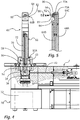
- FIG. 5 shows an application device 20 that represents the core component of a cavity preservation device 10.
- this application device 20 is provided for coupling to a robot arm 14 and, for this purpose, has a coupling device 24, which also includes supply and control lines, as will be explained below.
- the application device 20 has a rotary drive unit 30 with an in Fig. 1 Internal electric motor, not shown, which is provided to be able to rotate a rotatable rotor unit 50 about an axis of rotation 2.
- the electric motor 32 can not only rotate the rotor unit 50 to a limited extent between two end positions, but also freely through 360 ° and endlessly.
- the application device 20 has a mixing nozzle unit 60 which is attached to the rotor unit 50 in a rotationally fixed manner by means of a nut 58.
- the mixing nozzle unit 60 has an elongated shaft 66, the proximal end 60A of which is fixed by the nut 58.
- a mixing nozzle 80 is provided, which is aligned in the radial direction, so that fluid discharged here is discharged in a discharge direction that encloses an angle of approximately 90 ° with the axis of rotation 2.
- smaller angles can also be provided, for example 60 ° and more.
- connection 26 through which cavity preservatives, compressed air, electrical energy and control signals are transmitted.
- the 4 and 5 show the application device 20 and the mixing nozzle unit 60 in an enlarged and sectional illustration.
- the application device 20 is located in the area of the mixing nozzle unit 60 via the rotary drive unit 30, which only schematically shows in Fig. 4 includes electric motor 32 shown.
- This is provided for driving the rotor 50, which has a thread at its upper end, by means of which the nut 58 is screwed onto the rotor 50.
- the nut 58 has a conical inside corresponding to a likewise conical coupling device 62 on the side of the mixing nozzle unit 60.
- the rotor unit 50 is rotatably mounted on a base of the application device 20 by means of a roller bearing 52.
- the mixing nozzle unit 60 consists of three main components, namely an outer tube 64A, an inner tube 64B and a nozzle receptacle 64C, in which the mixing nozzle 80 is fastened.
- This design allows the mixing nozzle unit to be easily reconfigured by replacing components 64A, 64B with components of different lengths. As a result, mixing nozzle units with different maximum immersion depths can be used.
- a supply channel 70 for supplying the cavity preservative extends inside the inner tube 64B and continues into the component 64C. At its distal end, this feed channel 70 has a deflection 70A, at which incoming cavity preservative is deflected from an axial flow direction into a radial flow direction.
- a feed channel 72 is also created between the outside of the inner tube 64B and the inside of the outer tube 64A, which also continues into the component 64C and is deflected there in a deflection area 72A in the radial direction.
- Both fluids, the cavity preservative and gas used for atomization thus already diverted in the radial direction to the mixing nozzle 80, where in the case of the illustrated configuration of the mixing nozzle 80 they are directed to separate outlet openings 82, 84, at which they are released under pressure.
- the leaked cavity preservative 92 is atomized and forms a fine protective agent mist 96.
- the supply channels 70, 72 are supplied by the rotor unit 50, which for this purpose is also provided in the following 6 to 8 recognizable way has a central cavity preservative channel 54 and surrounding gas channels 56. As with the Fig. 4 , but especially the 7 and 8 It can be seen that rotary unions 43, 47 are provided, by means of which the channels 54, 56 are permanently connected to corresponding channels 42, 46 of the base. These channels 42, 46 are supplied by the aforementioned connections 26 on the coupling device 24, a switching valve 44 being provided in the channel 42 for the cavity preservative, by means of which the supply of cavity preservative is comparatively close to the discharge opening 84 can be interrupted.
- the valve 44 is provided as a pneumatically switchable valve.
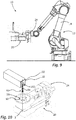
- Fig. 9 shows the intended main use of a spreading device according to the preceding figures.
- the application device 20 is attached with its coupling device 24 to a robot arm 14, by means of which the application device can be moved in flexible space, in particular in order to be moved relative to a vehicle chassis and to be brought into a working position.
- Fig. 10 shows such a working position.
- the mixing nozzle unit 60 is partially inserted through an opening 102 into a hollow body 100.
- the mixing nozzle unit 60 is rotated by means of the rotor unit 50 and the electric motor 32 as intended while simultaneously generating a protective agent mist.
- the spray 94 generated can therefore be applied in different directions and to all inner surfaces of the hollow body 100.
- Fig. 11 shows an orientation of the mixing nozzle in the direction of extension of the elongated hollow body 100. A particularly large amount of protective agent mist is required in this direction, since the inner surfaces arranged in this direction are comparatively large.
- Fig. 12 shows an orientation at 90 ° to that of Fig. 11 . In this orientation, the mixing nozzle is directed towards a relatively close wall, so that the surfaces to be coated in this angular range are smaller. A smaller amount of cavity preservative per angular unit is therefore also required.
- Fig. 13 shows an orientation in which no discharge of cavity preservative is desired.
- the valve 44 can remain open over the major part of a 360 ° rotation of the mixing nozzle unit 60 and only in the orientation of the Fig. 13 getting closed.
- the different amount of cavity preservative depending on the angle corresponding to the 11 and 12 it can be provided that, at a constant rotational speed of the mixing nozzle unit 60, the valve 44 or another electrically operated valve the flow of the cavity preservative in the angular position of the Fig. 12 towards the position of the Fig. 11 decreased.
- the speed of rotation of the mixing nozzle unit in the angular position of the Fig. 12 is considerably larger than in the angular position Fig. 11 be.
Landscapes
- Engineering & Computer Science (AREA)
- Robotics (AREA)
- Mechanical Engineering (AREA)
- Nozzles (AREA)
Priority Applications (5)
| Application Number | Priority Date | Filing Date | Title |
|---|---|---|---|
| EP18213643.2A EP3670001B1 (fr) | 2018-12-18 | 2018-12-18 | Procédé de conservation d'espace creux, buse de mélange et dispositif de conservation d'espace creux doté d'une telle buse de mélange |
| US17/415,320 US12311395B2 (en) | 2018-12-18 | 2019-11-06 | Method for preserving cavities, mixing nozzle unit and cavity-preserving device having a mixing nozzle unit of this type |
| CN201980084370.9A CN113242769A (zh) | 2018-12-18 | 2019-11-06 | 用于空腔防腐的方法、混合喷嘴单元以及具有这种混合喷嘴单元的空腔防腐装置 |
| PCT/EP2019/080438 WO2020126199A1 (fr) | 2018-12-18 | 2019-11-06 | Procédé de protection d'espace creux, unité de buse de mélange et dispositif de protection d'espace creux comprenant une telle unité de buse de mélange |
| MX2021007333A MX2021007333A (es) | 2018-12-18 | 2019-11-06 | Metodo para conservar cavidades, unidad de boquilla de mezcla y dispositivo de conservacion de cavidad que tiene una unidad de boquilla de mezcla de este tipo. |
Applications Claiming Priority (1)
| Application Number | Priority Date | Filing Date | Title |
|---|---|---|---|
| EP18213643.2A EP3670001B1 (fr) | 2018-12-18 | 2018-12-18 | Procédé de conservation d'espace creux, buse de mélange et dispositif de conservation d'espace creux doté d'une telle buse de mélange |
Publications (2)
| Publication Number | Publication Date |
|---|---|
| EP3670001A1 true EP3670001A1 (fr) | 2020-06-24 |
| EP3670001B1 EP3670001B1 (fr) | 2021-07-28 |
Family
ID=64745946
Family Applications (1)
| Application Number | Title | Priority Date | Filing Date |
|---|---|---|---|
| EP18213643.2A Active EP3670001B1 (fr) | 2018-12-18 | 2018-12-18 | Procédé de conservation d'espace creux, buse de mélange et dispositif de conservation d'espace creux doté d'une telle buse de mélange |
Country Status (5)
| Country | Link |
|---|---|
| US (1) | US12311395B2 (fr) |
| EP (1) | EP3670001B1 (fr) |
| CN (1) | CN113242769A (fr) |
| MX (1) | MX2021007333A (fr) |
| WO (1) | WO2020126199A1 (fr) |
Citations (7)
| Publication number | Priority date | Publication date | Assignee | Title |
|---|---|---|---|---|
| JPH06206025A (ja) * | 1993-01-07 | 1994-07-26 | Toyota Motor Corp | 回転式内面溶射装置 |
| US6206300B1 (en) * | 1999-07-30 | 2001-03-27 | Curtis Dyna-Fog, Lyd. | Aerosol generator |
| US6632475B1 (en) * | 2000-10-06 | 2003-10-14 | Nicola Bleggi | Method of lining underground pipes and apparatus for performing the method |
| JP3699770B2 (ja) * | 1996-02-21 | 2005-09-28 | ユーキャン株式会社 | 噴霧装置 |
| DE102010034921A1 (de) | 2010-08-20 | 2012-02-23 | Dürr Systems GmbH | Düse zur Applikation eines Auftragsmittels |
| FR3014334A3 (fr) * | 2013-12-05 | 2015-06-12 | Renault Sa | Buse d'une platine d'injection de cire |
| WO2017013620A1 (fr) | 2015-07-21 | 2017-01-26 | Readynovation | Dispositif de connexion pour sangles, objets parties de vetements et accessoires. |
Family Cites Families (12)
| Publication number | Priority date | Publication date | Assignee | Title |
|---|---|---|---|---|
| US3120346A (en) * | 1962-10-31 | 1964-02-04 | American Mach & Foundry | Rotary spray devices |
| JPS56161870A (en) * | 1980-05-14 | 1981-12-12 | Sumitomo Light Metal Ind Ltd | Method and apparatus for coating long pipe having small diameter |
| JP4245553B2 (ja) * | 2004-11-26 | 2009-03-25 | Lui株式会社 | 金型の離型剤塗布装置 |
| US8480011B2 (en) * | 2007-09-04 | 2013-07-09 | Dehn's Innovations, Llc | Nozzle system and method |
| DE102009001396B4 (de) | 2009-03-09 | 2013-09-05 | Albrecht von Linde | Sprühvorrichtung |
| EP2286925B1 (fr) | 2009-08-20 | 2018-03-14 | Sulzer Mixpac AG | Pulvérisateur avec mélangeur statique |
| CN202539010U (zh) * | 2012-02-15 | 2012-11-21 | 常州市璟胜自动化科技有限公司 | 喷涂机反冲洗装置 |
| DK2730345T3 (en) | 2012-11-08 | 2016-10-24 | Alfa Laval Corp Ab | Fluid system with exhaust nozzle with two outputs |
| SG11201606398RA (en) * | 2014-02-19 | 2016-09-29 | Ant Applied New Technologies Ag | Nozzle head |
| US9500463B2 (en) | 2014-07-29 | 2016-11-22 | Caterpillar Inc. | Rotating bore sprayer alignment indicator assembly |
| EP3205407B1 (fr) * | 2016-02-09 | 2019-09-25 | IPR-Intelligente Peripherien für Roboter GmbH | Procede et installation destines a revetir les parois interieures d'un espace creux a l'aide d'une couche de protection anticorrosion a base de cire |
| CN206305409U (zh) * | 2016-12-06 | 2017-07-07 | 东莞市耀星机器人科技有限公司 | 喷雾装置和喷雾设备 |
-
2018
- 2018-12-18 EP EP18213643.2A patent/EP3670001B1/fr active Active
-
2019
- 2019-11-06 CN CN201980084370.9A patent/CN113242769A/zh active Pending
- 2019-11-06 WO PCT/EP2019/080438 patent/WO2020126199A1/fr not_active Ceased
- 2019-11-06 MX MX2021007333A patent/MX2021007333A/es unknown
- 2019-11-06 US US17/415,320 patent/US12311395B2/en active Active
Patent Citations (7)
| Publication number | Priority date | Publication date | Assignee | Title |
|---|---|---|---|---|
| JPH06206025A (ja) * | 1993-01-07 | 1994-07-26 | Toyota Motor Corp | 回転式内面溶射装置 |
| JP3699770B2 (ja) * | 1996-02-21 | 2005-09-28 | ユーキャン株式会社 | 噴霧装置 |
| US6206300B1 (en) * | 1999-07-30 | 2001-03-27 | Curtis Dyna-Fog, Lyd. | Aerosol generator |
| US6632475B1 (en) * | 2000-10-06 | 2003-10-14 | Nicola Bleggi | Method of lining underground pipes and apparatus for performing the method |
| DE102010034921A1 (de) | 2010-08-20 | 2012-02-23 | Dürr Systems GmbH | Düse zur Applikation eines Auftragsmittels |
| FR3014334A3 (fr) * | 2013-12-05 | 2015-06-12 | Renault Sa | Buse d'une platine d'injection de cire |
| WO2017013620A1 (fr) | 2015-07-21 | 2017-01-26 | Readynovation | Dispositif de connexion pour sangles, objets parties de vetements et accessoires. |
Also Published As
| Publication number | Publication date |
|---|---|
| WO2020126199A1 (fr) | 2020-06-25 |
| US20220062937A1 (en) | 2022-03-03 |
| CN113242769A (zh) | 2021-08-10 |
| MX2021007333A (es) | 2021-09-30 |
| US12311395B2 (en) | 2025-05-27 |
| EP3670001B1 (fr) | 2021-07-28 |
Similar Documents
| Publication | Publication Date | Title |
|---|---|---|
| EP1351009B1 (fr) | Dispositif et méthode de revêtement de la surface intérieure d'un tuyau | |
| EP2605859B1 (fr) | Buse pour l'application d'un agent d'enduction | |
| EP2704850B1 (fr) | Pulvérisateur de peinture | |
| EP2451586B1 (fr) | Pistolet pulvérisateur à peinture | |
| DE3419964C2 (de) | Spritzkopf eines Hochdruckreinigungsgerätes | |
| EP1340550A2 (fr) | Pistolet de pulvérisation | |
| EP2134475A1 (fr) | Dispositif pour pulvériser des liquides pigmentés | |
| EP2228136B1 (fr) | Dispositif de vaporisation | |
| EP1912745B1 (fr) | Dispositif de pulverisation de liquides pigmentes | |
| DE69724400T2 (de) | Vorrichtung mit kontrolliertem Abgabemuster | |
| DE102014016207A1 (de) | Applikator zur Applikation eines Auftragsmaterials | |
| EP3113887B1 (fr) | Dispositif d'extension pour appareils de pulvérisation et appareils de pulvérisation | |
| EP2485848B1 (fr) | Buse | |
| DE102016001188A1 (de) | Applikator zur Applikation eines Auftragsmaterials | |
| DE3151929C2 (de) | Vorrichtung zum aufeinanderfolgenden Auftragen verschiedener Überzugsflüssigkeiten | |
| DE2757522C2 (de) | Rund- oder Ringstrahldüse zum Erzeugen und Abstrahlen eines Nebels oder Aerosols zur Beschichtung von Gegenständen | |
| EP3670001B1 (fr) | Procédé de conservation d'espace creux, buse de mélange et dispositif de conservation d'espace creux doté d'une telle buse de mélange | |
| DE4115395C2 (fr) | ||
| DE9206410U1 (de) | Spritzvorrichtung für die Innenwände von Hohlkörpern | |
| WO2017008887A1 (fr) | Vanne pour agent de revêtement | |
| DE903460C (de) | Bestaeubungsvorrichtung fuer Druckbogen | |
| DE10209485B4 (de) | Vorrichtung zur Innenbeschichtung eines Rohres | |
| DE102006056230A1 (de) | Vorrichtung zum Innenbeschichten eines Hohlkörpers | |
| DE202015009893U1 (de) | Roboterwerkzeug und Roboter zur Abgabe eines Korrosionsschutzwachses | |
| DE3336873A1 (de) | Duesenkopf fuer vorrichtungen zum feindosierten auftragen von fluessigen bis pastoesen medien auf oberflaechen |
Legal Events
| Date | Code | Title | Description |
|---|---|---|---|
| PUAI | Public reference made under article 153(3) epc to a published international application that has entered the european phase |
Free format text: ORIGINAL CODE: 0009012 |
|
| STAA | Information on the status of an ep patent application or granted ep patent |
Free format text: STATUS: THE APPLICATION HAS BEEN PUBLISHED |
|
| AK | Designated contracting states |
Kind code of ref document: A1 Designated state(s): AL AT BE BG CH CY CZ DE DK EE ES FI FR GB GR HR HU IE IS IT LI LT LU LV MC MK MT NL NO PL PT RO RS SE SI SK SM TR |
|
| AX | Request for extension of the european patent |
Extension state: BA ME |
|
| STAA | Information on the status of an ep patent application or granted ep patent |
Free format text: STATUS: REQUEST FOR EXAMINATION WAS MADE |
|
| 17P | Request for examination filed |
Effective date: 20200911 |
|
| RBV | Designated contracting states (corrected) |
Designated state(s): AL AT BE BG CH CY CZ DE DK EE ES FI FR GB GR HR HU IE IS IT LI LT LU LV MC MK MT NL NO PL PT RO RS SE SI SK SM TR |
|
| RIC1 | Information provided on ipc code assigned before grant |
Ipc: B05B 15/68 20180101ALI20210128BHEP Ipc: B05B 13/06 20060101ALI20210128BHEP Ipc: B05B 15/652 20180101ALI20210128BHEP Ipc: B05B 7/06 20060101ALN20210128BHEP Ipc: B05B 13/04 20060101AFI20210128BHEP Ipc: B05B 12/12 20060101ALI20210128BHEP Ipc: B25J 11/00 20060101ALI20210128BHEP Ipc: B05B 3/02 20060101ALN20210128BHEP |
|
| GRAP | Despatch of communication of intention to grant a patent |
Free format text: ORIGINAL CODE: EPIDOSNIGR1 |
|
| STAA | Information on the status of an ep patent application or granted ep patent |
Free format text: STATUS: GRANT OF PATENT IS INTENDED |
|
| RIC1 | Information provided on ipc code assigned before grant |
Ipc: B05B 15/68 20180101ALI20210301BHEP Ipc: B05B 12/12 20060101ALI20210301BHEP Ipc: B05B 3/02 20060101ALN20210301BHEP Ipc: B25J 11/00 20060101ALI20210301BHEP Ipc: B05B 7/06 20060101ALN20210301BHEP Ipc: B05B 15/652 20180101ALI20210301BHEP Ipc: B05B 13/06 20060101ALI20210301BHEP Ipc: B05B 13/04 20060101AFI20210301BHEP |
|
| INTG | Intention to grant announced |
Effective date: 20210317 |
|
| GRAS | Grant fee paid |
Free format text: ORIGINAL CODE: EPIDOSNIGR3 |
|
| GRAA | (expected) grant |
Free format text: ORIGINAL CODE: 0009210 |
|
| STAA | Information on the status of an ep patent application or granted ep patent |
Free format text: STATUS: THE PATENT HAS BEEN GRANTED |
|
| AK | Designated contracting states |
Kind code of ref document: B1 Designated state(s): AL AT BE BG CH CY CZ DE DK EE ES FI FR GB GR HR HU IE IS IT LI LT LU LV MC MK MT NL NO PL PT RO RS SE SI SK SM TR |
|
| REG | Reference to a national code |
Ref country code: GB Ref legal event code: FG4D Free format text: NOT ENGLISH |
|
| REG | Reference to a national code |
Ref country code: CH Ref legal event code: EP |
|
| REG | Reference to a national code |
Ref country code: DE Ref legal event code: R096 Ref document number: 502018006298 Country of ref document: DE |
|
| REG | Reference to a national code |
Ref country code: AT Ref legal event code: REF Ref document number: 1414236 Country of ref document: AT Kind code of ref document: T Effective date: 20210815 |
|
| REG | Reference to a national code |
Ref country code: IE Ref legal event code: FG4D Free format text: LANGUAGE OF EP DOCUMENT: GERMAN |
|
| REG | Reference to a national code |
Ref country code: LT Ref legal event code: MG9D |
|
| REG | Reference to a national code |
Ref country code: NL Ref legal event code: MP Effective date: 20210728 |
|
| PG25 | Lapsed in a contracting state [announced via postgrant information from national office to epo] |
Ref country code: HR Free format text: LAPSE BECAUSE OF FAILURE TO SUBMIT A TRANSLATION OF THE DESCRIPTION OR TO PAY THE FEE WITHIN THE PRESCRIBED TIME-LIMIT Effective date: 20210728 Ref country code: ES Free format text: LAPSE BECAUSE OF FAILURE TO SUBMIT A TRANSLATION OF THE DESCRIPTION OR TO PAY THE FEE WITHIN THE PRESCRIBED TIME-LIMIT Effective date: 20210728 Ref country code: FI Free format text: LAPSE BECAUSE OF FAILURE TO SUBMIT A TRANSLATION OF THE DESCRIPTION OR TO PAY THE FEE WITHIN THE PRESCRIBED TIME-LIMIT Effective date: 20210728 Ref country code: RS Free format text: LAPSE BECAUSE OF FAILURE TO SUBMIT A TRANSLATION OF THE DESCRIPTION OR TO PAY THE FEE WITHIN THE PRESCRIBED TIME-LIMIT Effective date: 20210728 Ref country code: SE Free format text: LAPSE BECAUSE OF FAILURE TO SUBMIT A TRANSLATION OF THE DESCRIPTION OR TO PAY THE FEE WITHIN THE PRESCRIBED TIME-LIMIT Effective date: 20210728 Ref country code: BG Free format text: LAPSE BECAUSE OF FAILURE TO SUBMIT A TRANSLATION OF THE DESCRIPTION OR TO PAY THE FEE WITHIN THE PRESCRIBED TIME-LIMIT Effective date: 20211028 Ref country code: LT Free format text: LAPSE BECAUSE OF FAILURE TO SUBMIT A TRANSLATION OF THE DESCRIPTION OR TO PAY THE FEE WITHIN THE PRESCRIBED TIME-LIMIT Effective date: 20210728 Ref country code: NL Free format text: LAPSE BECAUSE OF FAILURE TO SUBMIT A TRANSLATION OF THE DESCRIPTION OR TO PAY THE FEE WITHIN THE PRESCRIBED TIME-LIMIT Effective date: 20210728 Ref country code: NO Free format text: LAPSE BECAUSE OF FAILURE TO SUBMIT A TRANSLATION OF THE DESCRIPTION OR TO PAY THE FEE WITHIN THE PRESCRIBED TIME-LIMIT Effective date: 20211028 Ref country code: PT Free format text: LAPSE BECAUSE OF FAILURE TO SUBMIT A TRANSLATION OF THE DESCRIPTION OR TO PAY THE FEE WITHIN THE PRESCRIBED TIME-LIMIT Effective date: 20211129 |
|
| PG25 | Lapsed in a contracting state [announced via postgrant information from national office to epo] |
Ref country code: PL Free format text: LAPSE BECAUSE OF FAILURE TO SUBMIT A TRANSLATION OF THE DESCRIPTION OR TO PAY THE FEE WITHIN THE PRESCRIBED TIME-LIMIT Effective date: 20210728 Ref country code: LV Free format text: LAPSE BECAUSE OF FAILURE TO SUBMIT A TRANSLATION OF THE DESCRIPTION OR TO PAY THE FEE WITHIN THE PRESCRIBED TIME-LIMIT Effective date: 20210728 Ref country code: GR Free format text: LAPSE BECAUSE OF FAILURE TO SUBMIT A TRANSLATION OF THE DESCRIPTION OR TO PAY THE FEE WITHIN THE PRESCRIBED TIME-LIMIT Effective date: 20211029 |
|
| REG | Reference to a national code |
Ref country code: DE Ref legal event code: R082 Ref document number: 502018006298 Country of ref document: DE Representative=s name: WITTE, WELLER & PARTNER PATENTANWAELTE MBB, DE |
|
| PG25 | Lapsed in a contracting state [announced via postgrant information from national office to epo] |
Ref country code: DK Free format text: LAPSE BECAUSE OF FAILURE TO SUBMIT A TRANSLATION OF THE DESCRIPTION OR TO PAY THE FEE WITHIN THE PRESCRIBED TIME-LIMIT Effective date: 20210728 |
|
| REG | Reference to a national code |
Ref country code: DE Ref legal event code: R097 Ref document number: 502018006298 Country of ref document: DE |
|
| PG25 | Lapsed in a contracting state [announced via postgrant information from national office to epo] |
Ref country code: SM Free format text: LAPSE BECAUSE OF FAILURE TO SUBMIT A TRANSLATION OF THE DESCRIPTION OR TO PAY THE FEE WITHIN THE PRESCRIBED TIME-LIMIT Effective date: 20210728 Ref country code: SK Free format text: LAPSE BECAUSE OF FAILURE TO SUBMIT A TRANSLATION OF THE DESCRIPTION OR TO PAY THE FEE WITHIN THE PRESCRIBED TIME-LIMIT Effective date: 20210728 Ref country code: RO Free format text: LAPSE BECAUSE OF FAILURE TO SUBMIT A TRANSLATION OF THE DESCRIPTION OR TO PAY THE FEE WITHIN THE PRESCRIBED TIME-LIMIT Effective date: 20210728 Ref country code: EE Free format text: LAPSE BECAUSE OF FAILURE TO SUBMIT A TRANSLATION OF THE DESCRIPTION OR TO PAY THE FEE WITHIN THE PRESCRIBED TIME-LIMIT Effective date: 20210728 Ref country code: CZ Free format text: LAPSE BECAUSE OF FAILURE TO SUBMIT A TRANSLATION OF THE DESCRIPTION OR TO PAY THE FEE WITHIN THE PRESCRIBED TIME-LIMIT Effective date: 20210728 Ref country code: AL Free format text: LAPSE BECAUSE OF FAILURE TO SUBMIT A TRANSLATION OF THE DESCRIPTION OR TO PAY THE FEE WITHIN THE PRESCRIBED TIME-LIMIT Effective date: 20210728 |
|
| PLBE | No opposition filed within time limit |
Free format text: ORIGINAL CODE: 0009261 |
|
| STAA | Information on the status of an ep patent application or granted ep patent |
Free format text: STATUS: NO OPPOSITION FILED WITHIN TIME LIMIT |
|
| 26N | No opposition filed |
Effective date: 20220429 |
|
| PG25 | Lapsed in a contracting state [announced via postgrant information from national office to epo] |
Ref country code: MC Free format text: LAPSE BECAUSE OF FAILURE TO SUBMIT A TRANSLATION OF THE DESCRIPTION OR TO PAY THE FEE WITHIN THE PRESCRIBED TIME-LIMIT Effective date: 20210728 Ref country code: IT Free format text: LAPSE BECAUSE OF FAILURE TO SUBMIT A TRANSLATION OF THE DESCRIPTION OR TO PAY THE FEE WITHIN THE PRESCRIBED TIME-LIMIT Effective date: 20210728 |
|
| REG | Reference to a national code |
Ref country code: CH Ref legal event code: PL |
|
| REG | Reference to a national code |
Ref country code: BE Ref legal event code: MM Effective date: 20211231 |
|
| PG25 | Lapsed in a contracting state [announced via postgrant information from national office to epo] |
Ref country code: LU Free format text: LAPSE BECAUSE OF NON-PAYMENT OF DUE FEES Effective date: 20211218 Ref country code: IE Free format text: LAPSE BECAUSE OF NON-PAYMENT OF DUE FEES Effective date: 20211218 |
|
| PG25 | Lapsed in a contracting state [announced via postgrant information from national office to epo] |
Ref country code: BE Free format text: LAPSE BECAUSE OF NON-PAYMENT OF DUE FEES Effective date: 20211231 |
|
| PG25 | Lapsed in a contracting state [announced via postgrant information from national office to epo] |
Ref country code: LI Free format text: LAPSE BECAUSE OF NON-PAYMENT OF DUE FEES Effective date: 20211231 Ref country code: CH Free format text: LAPSE BECAUSE OF NON-PAYMENT OF DUE FEES Effective date: 20211231 |
|
| P01 | Opt-out of the competence of the unified patent court (upc) registered |
Effective date: 20230502 |
|
| PG25 | Lapsed in a contracting state [announced via postgrant information from national office to epo] |
Ref country code: CY Free format text: LAPSE BECAUSE OF FAILURE TO SUBMIT A TRANSLATION OF THE DESCRIPTION OR TO PAY THE FEE WITHIN THE PRESCRIBED TIME-LIMIT Effective date: 20210728 |
|
| PG25 | Lapsed in a contracting state [announced via postgrant information from national office to epo] |
Ref country code: HU Free format text: LAPSE BECAUSE OF FAILURE TO SUBMIT A TRANSLATION OF THE DESCRIPTION OR TO PAY THE FEE WITHIN THE PRESCRIBED TIME-LIMIT; INVALID AB INITIO Effective date: 20181218 |
|
| PG25 | Lapsed in a contracting state [announced via postgrant information from national office to epo] |
Ref country code: MK Free format text: LAPSE BECAUSE OF FAILURE TO SUBMIT A TRANSLATION OF THE DESCRIPTION OR TO PAY THE FEE WITHIN THE PRESCRIBED TIME-LIMIT Effective date: 20210728 |
|
| PG25 | Lapsed in a contracting state [announced via postgrant information from national office to epo] |
Ref country code: MT Free format text: LAPSE BECAUSE OF FAILURE TO SUBMIT A TRANSLATION OF THE DESCRIPTION OR TO PAY THE FEE WITHIN THE PRESCRIBED TIME-LIMIT Effective date: 20210728 |
|
| REG | Reference to a national code |
Ref country code: AT Ref legal event code: MM01 Ref document number: 1414236 Country of ref document: AT Kind code of ref document: T Effective date: 20231218 |
|
| PG25 | Lapsed in a contracting state [announced via postgrant information from national office to epo] |
Ref country code: AT Free format text: LAPSE BECAUSE OF NON-PAYMENT OF DUE FEES Effective date: 20231218 |
|
| PG25 | Lapsed in a contracting state [announced via postgrant information from national office to epo] |
Ref country code: TR Free format text: LAPSE BECAUSE OF FAILURE TO SUBMIT A TRANSLATION OF THE DESCRIPTION OR TO PAY THE FEE WITHIN THE PRESCRIBED TIME-LIMIT Effective date: 20210728 |
|
| PGFP | Annual fee paid to national office [announced via postgrant information from national office to epo] |
Ref country code: DE Payment date: 20251217 Year of fee payment: 8 |
|
| PGFP | Annual fee paid to national office [announced via postgrant information from national office to epo] |
Ref country code: GB Payment date: 20251219 Year of fee payment: 8 |
|
| PGFP | Annual fee paid to national office [announced via postgrant information from national office to epo] |
Ref country code: FR Payment date: 20251229 Year of fee payment: 8 |
|
| PGFP | Annual fee paid to national office [announced via postgrant information from national office to epo] |
Ref country code: AT Payment date: 20260410 Year of fee payment: 5 |