EP3670045A1 - Mandrin de serrage à extension hydraulique ainsi qu'unité d'avance du forage - Google Patents
Mandrin de serrage à extension hydraulique ainsi qu'unité d'avance du forage Download PDFInfo
- Publication number
- EP3670045A1 EP3670045A1 EP18214184.6A EP18214184A EP3670045A1 EP 3670045 A1 EP3670045 A1 EP 3670045A1 EP 18214184 A EP18214184 A EP 18214184A EP 3670045 A1 EP3670045 A1 EP 3670045A1
- Authority
- EP
- European Patent Office
- Prior art keywords
- chuck
- drill
- receptacle
- feed unit
- pressure
- Prior art date
- Legal status (The legal status is an assumption and is not a legal conclusion. Google has not performed a legal analysis and makes no representation as to the accuracy of the status listed.)
- Granted
Links
Images

Classifications
-
- B—PERFORMING OPERATIONS; TRANSPORTING
- B23—MACHINE TOOLS; METAL-WORKING NOT OTHERWISE PROVIDED FOR
- B23B—TURNING; BORING
- B23B31/00—Chucks; Expansion mandrels; Adaptations thereof for remote control
- B23B31/02—Chucks
- B23B31/24—Chucks characterised by features relating primarily to remote control of the gripping means
- B23B31/30—Chucks characterised by features relating primarily to remote control of the gripping means using fluid-pressure means in the chuck
- B23B31/305—Chucks characterised by features relating primarily to remote control of the gripping means using fluid-pressure means in the chuck the gripping means is a deformable sleeve
-
- B—PERFORMING OPERATIONS; TRANSPORTING
- B23—MACHINE TOOLS; METAL-WORKING NOT OTHERWISE PROVIDED FOR
- B23B—TURNING; BORING
- B23B31/00—Chucks; Expansion mandrels; Adaptations thereof for remote control
- B23B31/02—Chucks
- B23B31/10—Chucks characterised by the retaining or gripping devices or their immediate operating means
- B23B31/117—Retention by friction only, e.g. using springs, resilient sleeves, tapers
- B23B31/1177—Retention by friction only, e.g. using springs, resilient sleeves, tapers using resilient metallic rings or sleeves
- B23B31/1178—Retention by friction only, e.g. using springs, resilient sleeves, tapers using resilient metallic rings or sleeves using fluid-pressure means to actuate the gripping means
-
- B—PERFORMING OPERATIONS; TRANSPORTING
- B23—MACHINE TOOLS; METAL-WORKING NOT OTHERWISE PROVIDED FOR
- B23Q—DETAILS, COMPONENTS, OR ACCESSORIES FOR MACHINE TOOLS, e.g. ARRANGEMENTS FOR COPYING OR CONTROLLING; MACHINE TOOLS IN GENERAL CHARACTERISED BY THE CONSTRUCTION OF PARTICULAR DETAILS OR COMPONENTS; COMBINATIONS OR ASSOCIATIONS OF METAL-WORKING MACHINES, NOT DIRECTED TO A PARTICULAR RESULT
- B23Q5/00—Driving or feeding mechanisms; Control arrangements therefor
- B23Q5/22—Feeding members carrying tools or work
- B23Q5/26—Fluid-pressure drives
- B23Q5/261—Fluid-pressure drives for spindles
Definitions
- the invention relates to a hydraulic chuck and a drilling feed unit.
- the invention is therefore based on the object of creating a hydraulic expansion chuck and a drilling feed unit, the disadvantages mentioned being alleviated or avoided.
- a hydraulic expansion chuck which has a clamping receptacle for releasably clamping a tool.
- the hydraulic expansion chuck preferably has a maximum width dimension perpendicular to a longitudinal axis of the hydraulic expansion chuck of at least 5 mm to at most 40 mm, preferably from at least 7 mm to at most 35 mm, preferably from at least 10 mm to at most 30 mm, preferably from at least 15 mm to at most 20 mm, on.
- a particularly small hydraulic expansion chuck is provided, which can be used for clamping a tool even in confined spaces.
- the hydraulic expansion chuck can be used in particular instead of an adapter piece that would otherwise be permanently attached to the tool.
- a longitudinal axis of the hydraulic expansion chuck is here in particular an axis which extends parallel to an intended longitudinal axis of a tool to be clamped in the clamping receptacle, the longitudinal axis of the hydraulic expansion chuck preferably coinciding with the longitudinal axis of the tool in the clamped state.
- the longitudinal axis of the hydraulic expansion chuck is preferably an axis of the longest dimension of the hydraulic expansion chuck.
- the maximum width dimension is therefore preferably measured perpendicular to an axial direction of the tool releasably clamped in the clamping receptacle.
- the maximum width dimension is in particular a dimension of the greatest width of the hydraulic expansion chuck perpendicular to the longitudinal axis.
- the maximum width dimension is preferably an outer diameter of the hydraulic expansion chuck, which is preferably at least partially cylindrical, preferably at least partially circular cylindrical.
- the hydraulic expansion chuck preferably has a clamping space enclosed by a clamping wall, which is set up to receive a tool in some areas and to clamp the tool in the clamping chamber.
- At least one pressure chamber is formed in the clamping wall, which can preferably be filled or filled with a pressure fluid, in particular a pressure oil.
- a pressure fluid in particular a pressure oil.
- a second functional position of the hydraulic expansion chuck there is a second pressure value in the at least one pressure chamber, the inner surface of the clamping wall in the second functional position at the second pressure value not being deformed into the clamping space, but in particular being elastically displaced to an idle state in which the clamping space has a larger inner dimension, in particular a larger inner diameter, than when the inner surface of the clamping wall is deformed into the clamping space in the first functional position.
- the second pressure value is smaller than the first pressure value.
- the tool can be removed from the clamping area or a new tool can be moved into the clamping area. The tool is therefore released in the second functional position.
- the hydraulic chuck is reversibly shiftable from the first functional position to the second functional position - and vice versa.
- the hydraulic expansion chuck is in particular set up for use as an alternating chuck of a drilling feed unit according to the invention or a drilling feed unit according to one of the embodiments disclosed in accordance with the present technical teaching.
- the clamping receptacle is set up for releasably clamping a drill, preferably for such a drilling feed unit.
- the hydraulic expansion chuck of the clamping receptacle facing away from the longitudinal axis, has a connecting piece for mechanical connection with a receptacle for the hydraulic expansion chuck and also a centering surface, the centering surface being arranged offset radially outward from the connecting piece.
- the hydraulic expansion chuck can be simple, safe, reproducible and stable with a receptacle for the hydraulic expansion chuck, in particular with a drill receptacle and very particularly with an intermediate piece receptacle for a drilling feed unit, in particular a drilling feed unit according to the invention or a drilling feed unit according to one of the ones in accordance with the present technical teaching disclosed embodiments.
- the connecting piece enables the mechanical connection, the centering surface simultaneously allowing centering and axial alignment of the hydraulic expansion chuck relative to the receptacle. In particular, it can thus be ensured that the longitudinal axis of the hydraulic expansion chuck is aligned or coincides with the axial direction of the receptacle, in particular with the axial direction of the drilling feed unit.
- the receptacle preferably has a counter centering surface.
- the adapter receptacle preferably has a counter centering surface.
- the centering surface is in particular in full contact with the counter-centering surface, so that the hydraulic expansion chuck is centered on or in the receptacle.
- the fact that the centering surface is offset radially outward from the connecting piece contributes in a particularly advantageous manner to a stable and reproducible centering.
- the centering surface is preferably also offset axially from the connecting piece toward the clamping receptacle. In particular, it hurries behind the connecting piece in the assembly direction, so that during an assembly process the connecting piece first engages with the receptacle and finally the centering surface comes into contact with the counter surface.
- the connecting piece is designed as a threaded connector.
- the threaded connector is particularly preferred as a cylinder socket with an internal thread, or in a particularly preferred manner as Threaded socket with external thread.
- the threaded connector designed as a cylinder socket does not necessarily have to have a circular cylindrical geometry. Rather, the basic shape of the cylinder can also deviate from the circular geometry, for example have a polygonal or any other geometry.
- the term "cylinder” is used here in its most general form for the extrusion of any flat profile along an extrusion axis. However, the extrusion axis is preferably perpendicular to a profile plane of the profile.
- the centering surface is preferably designed as a truncated cone surface, in particular as an outer truncated cone surface.
- the counter centering surface in particular the counter centering surface of the drilling feed unit, is preferably designed as a truncated cone surface, in particular as an inner truncated cone surface.
- the centering surface and the counter-centering surface are designed to be complementary to one another, so that when the hydraulic expansion chuck is assembled, they can lie against one another and interact with one another over the entire surface of the receptacle.
- the at least one pressure chamber is connected in terms of flow with at least one pressure cylinder, a cylinder longitudinal axis of the at least one pressure cylinder enclosing an angle with the longitudinal axis of the hydraulic expansion chuck that is from at least 0 ° to at most 3 °, preferably of at least 1 ° to at most 2 °, preferably 1.5 °.
- a cylinder longitudinal axis of a pressure cylinder typically has a much larger angle to the longitudinal axis of the hydraulic expansion chuck, wherein the cylinder longitudinal axis of the pressure cylinder can in particular be perpendicular to the longitudinal axis of the hydraulic expansion chuck. This requires a significantly larger installation space.
- a pressure piston is preferably arranged displaceably in the at least one pressure cylinder.
- the volume available for the pressure fluid can be changed so that the pressure fluid in the pressurized first functional position and can be relaxed in the second functional position relative to the first functional position.
- the first pressure value and the second pressure value can thus be provided in particular by suitable displacement of the pressure piston in the pressure cylinder, the pressure piston in the pressure cylinder leaving a smaller volume for the pressure fluid in the first functional position, and consequently being displaced into the pressure cylinder, wherein it the second functional position releases a larger volume for the pressure fluid, thus a certain distance out of the pressure cylinder or in the pressure cylinder is shifted away from the pressure chamber.
- a pressure screw bore is assigned to the at least one pressure cylinder.
- a longitudinal axis of the pressure screw hole is aligned parallel to the longitudinal axis of the pressure cylinder. This enables a particularly simple actuation of the pressure piston in the pressure cylinder via the pressure screw hole.
- the longitudinal axis of the pressure screw bore is offset perpendicular to the longitudinal axis of the cylinder from the longitudinal axis.
- the longitudinal axis of the pressure screw bore is therefore not aligned with the longitudinal axis of the cylinder, but rather is offset perpendicular to it, in particular offset in parallel.
- This configuration in particular enables a particularly small installation space for the hydraulic expansion chuck.
- the pressure screw bore typically has a larger diameter than the pressure cylinder, so that it takes up a comparatively large installation space perpendicular to the longitudinal axis or cylinder longitudinal axis.
- the longitudinal bore axis of the pressure screw bore is in particular offset radially inward to the longitudinal axis of the hydraulic expansion chuck relative to the cylinder longitudinal axis, so that, as a result, the pressure screw bore can at most have a slight oversize relative to an outermost position of the pressure cylinder.
- the pressure screw bore is in particular set up to receive a pressure screw, which in turn is set up to influence the pressure in the pressure cylinder and thus at the same time in the at least one pressure chamber.
- the pressure screw bore is operatively connected to the pressure cylinder; the pressure screw is particularly preferably operatively connected to the pressure piston for its actuation.
- the pressure screw is in contact with the pressure piston, so that the pressure piston by moving the Pressure screw, in particular by screwing in and / or unscrewing the pressure screw from or into the pressure screw bore, in which pressure cylinder can be displaced.
- the pressure screw is preferably designed as a grub screw. It preferably has an actuation intervention via which a torque can be introduced into the pressure screw.
- the actuation engagement is designed as a hexagon socket.
- the pressure chamber is fluidly connected to a plurality of pressure cylinders. This enables the hydraulic chuck to be further reduced in size. Typically, a certain displacement path of the pressure piston in the pressure cylinder is required in order to effect a volume displacement sufficient for stable and firm clamping of the tool in the clamping space. If this volume displacement is to be effected by only one pressure cylinder, this requires a certain minimum overall length for the pressure cylinder in the axial direction.
- each individual pressure cylinder can be made shorter because a correspondingly reduced displacement path must be provided for the individual pressure pistons.
- the hydraulic chuck can thus be made smaller in the axial direction.
- the at least one pressure screw bore opens into the centering surface.
- the centering surface can be used in an advantageous and space-saving manner at the same time on the one hand for centering the hydraulic expansion chuck and on the other hand for actuating the at least one pressure screw in the at least one pressure screw bore.
- the hydraulic expansion chuck has at least two pressure cylinders, in particular exactly two pressure cylinders, or exactly three pressure cylinders. These can be provided symmetrically along the circumferential line on the hydraulic chuck.
- the hydraulic expansion chuck it is also possible for the hydraulic expansion chuck to additionally have at least one, preferably exactly one, balancing bore; the pressure cylinders and pressure screw bores are then preferably arranged symmetrically along the circumferential line together with the balancing bore, in particular at equal angular distances from one another.
- the hydraulic expansion chuck has at least two key surfaces for introducing a torque into the hydraulic expansion chuck, the key surfaces preferably being formed on an outer peripheral wall of the hydraulic expansion chuck, in particular in the area of the clamping receptacle.
- a tool in particular a wrench, can engage the wrench surfaces in order to screw the hydraulic expansion chuck with the connecting piece, in particular the threaded connector, into a receptacle or to screw it onto the receptacle.
- Six key surfaces in the form of an external hexagon are particularly preferably provided, in particular at that end of the hydraulic expansion chuck at which the clamping receptacle is provided, and consequently opposite the connecting piece along the longitudinal axis.
- the hydrogen chuck is manufactured additively, in particular by 3D printing, in particular by means of powder bed-based, layer-by-layer melting of a metal powder, in particular by means of laser radiation, in particular by laser sintering or laser beam melting.
- the hydraulic chuck can be easily manufactured in one piece despite its comparatively complex geometry.
- the hydraulic expansion chuck preferably has an insertion chamfer or insertion round on the clamping receptacle, in particular at an opening of the clamping space. This serves to facilitate the insertion of a tool, in particular a drill, into the clamping space.
- a circumferential surface of the hydraulic expansion chuck is preferably at least partially cylindrical, in particular circular cylindrical.
- the hydraulic expansion chuck is particularly preferably of a circular cylindrical design, preferably with the exception of the centering surface, the connecting piece and / or the key surfaces.
- the hydraulic expansion chuck from the centering surface to the key surfaces - seen in the longitudinal direction - is circular cylindrical with respect to the outer peripheral surface, that is to say has a fully cylindrical, circular cylindrical peripheral surface. This represents a geometry that is particularly favorable for confined installation spaces.
- a drilling feed unit which has a drill receptacle which is set up to fasten a drill to the drilling feed unit.
- the drilling feed unit also has a feed device which is set up for the mechanical displacement of the drill receptacle relative to a housing of the drilling feed unit in the axial direction.
- the drill receptacle has an alternating chuck which is set up for releasable fastening - in particular for clamping in particular a cylindrical drill shaft - of the drill on the alternating chuck.
- the interchangeable chuck With the help of the interchangeable chuck, it is possible to change the drill bit in a simple and cost-effective manner, neither requiring additional complex and sometimes expensive materials and / or tools for changing the drill bit, nor an adapter piece that is permanently connected to the drill bit and that has to be provided with it would be disposed of together. Rather, the drill can be removed from the alternating chuck in a simple manner, it being possible for a new drill to be clamped in the alternating chuck.
- the drill receptacle is in particular set up for the portable fastening of the drill to the drilling feed unit, the drill being able to be mechanically displaced relative to the housing at the same time as the drill receptacle. In this way, the drill is advanced in the axial direction by the feed device.
- the drill receptacle is in particular set up for indirectly fastening the drill to the drill feed unit, in which case the drill receptacle is not itself designed as an alternating chuck, but is designed to fasten the alternating chuck to the drill receptacle.
- the drill holder itself to be designed as an alternating chuck, in which case it is set up for directly fastening the drill to the drilling feed unit.
- An axial direction here means in particular a direction which extends along a longitudinal direction of the drill and in particular along a feed direction, which is defined by the feed device and by the intended displacement of the drill holder relative to the housing, which can be effected by the feed device.
- the drill is rotated about its longitudinal axis in a manner known per se and is displaced along its longitudinal axis, that is to say in the axial direction.
- a radial direction is perpendicular to the axial direction, a circumferential direction concentrically encompasses the axial direction.
- the housing preferably receives the drill receptacle.
- the housing accommodates the feed device.
- the housing preferably encompasses the drill receptacle and / or the feed device at least in regions.
- the drill receptacle has an intermediate piece receptacle and an intermediate piece, the intermediate piece being set up to mechanically one end, that is to say at a first end, with the intermediate piece receptacle and at the other end, that is to say at a second, the first end along a longitudinal axis of the intermediate piece, preferably in the axial direction, opposite end to be connected to a drill.
- the intermediate piece is the interchangeable chuck of the drill feed unit for releasable fastening - in particular for clamping in particular a cylindrical drill shaft - of the drill.
- the drill receptacle is thus set up to indirectly fasten the drill to the drilling feed unit, the intermediate piece receptacle being set up to fasten the intermediate piece to the intermediate piece receptacle, the intermediate piece in turn being set up as an alternating chuck in order to releasably clamp the drill bit.
- the intermediate piece is designed to be attached to the intermediate piece receptacle at one end and to attach the drill to the intermediate piece at the other end.
- the intermediate piece is designed in particular at the second end as an alternating chuck.
- the intermediate piece in particular first be separated from the intermediate piece receptacle and then the drill can be released from the intermediate piece. A new drill can then be clamped into the intermediate piece designed as an alternating chuck, after which the intermediate piece is fastened again to the intermediate piece receptacle.
- This makes it possible, in particular, to remove the intermediate piece for changing the drill from the intermediate piece receptacle and thus from the drill receptacle, and thus to have more space available for actuating the alternating chuck.
- a user of the drilling feed unit therefore does not have to work in the confined space of the area of the drill receptacle in order to change the drill.
- the intermediate piece is an adapter piece, which does not have to be disposed of together with a worn drill, but rather is reused by unclamping a worn drill from the alternating chuck and clamping a new drill in the alternating chuck.
- the intermediate piece has a connecting piece at one end, in particular at the first end, which is set up for mechanically connecting the intermediate piece to the intermediate piece receptacle.
- the intermediate piece has a clamping receptacle for releasably clamping the drill. In this way, it is designed as an alternating chuck at the second end.
- the connecting piece is designed as a threaded connector which is set up for screwing the intermediate piece onto the intermediate piece receptacle.
- the threaded connector at the first end enables a particularly simple connection of the intermediate piece to the intermediate piece receptacle by screwing or screwing in.
- the threaded connector is preferably designed as a cylinder connector with an internal thread, or in a particularly preferred manner as a threaded connector with an external thread.
- the adapter piece has either a complementary external thread for screwing into the cylinder socket with an internal thread, or a complementary internal thread for screwing in the threaded connector with an external thread.
- the threaded connector designed as a cylinder connector need not necessarily have a circular cylindrical geometry. Rather, the basic shape of the cylinder can also deviate from the circular geometry, for example have a polygonal or any other geometry.
- the term "cylinder" is used here in its most general form for the extrusion of any flat profile along an extrusion axis. However, the extrusion axis is preferably perpendicular to a profile plane of the profile.
- the alternating chuck is selected from a group consisting of a hydraulic expansion chuck, a collet, a polygonal chuck, and a surface chuck. All of these chucks are suitable for the detachable attachment of a drill.
- a suitable exemplary embodiment of a hydraulic expansion chuck is described in more detail in accordance with the present technical teaching.
- An interchangeable chuck designed as a collet preferably has elastic clamping tongues in the radial direction, which can be shifted optionally into a clamping position and into a release position by means of a clamping cap or clamping nut.
- a polygonal chuck has a polygonal geometry that is created by applying an external pressure or an external force can be expanded to release a tool from the chuck or to insert a new tool into the chuck, removing external pressure or force causing the polygonal chuck to return to a clamping configuration in which the tool is clamped in the polygonal chuck .
- a surface chuck has in particular a clamping pin or a clamping screw which, in a clamping position, cooperates with a clamping surface of a tool in order to clamp the tool in the surface chuck, the tool being released from the surface chuck by moving the clamping pin or the clamping screw into a release position can.
- the drill receptacle is arranged at least in regions in a housing section of the housing.
- the drill receptacle is thus arranged on the inside of the housing, so that only a very cramped installation space is available for fastening the drill.
- the housing section is preferably a distal housing section, that is to say a housing section which is intended to face a workpiece to be machined.
- the drill receptacle is preferably displaceable in the housing section and relative to the housing section.
- the drill receptacle with the intermediate piece receptacle and preferably also with the intermediate piece is preferably arranged in the housing section at least in regions.
- the drill receptacle with the intermediate piece receptacle, the intermediate piece and the drill is particularly preferably arranged at least in regions in the housing section.
- the alternating chuck in particular the intermediate piece, has a maximum width dimension that is from at least 5 mm to at most 40 mm, preferably from at least 7 mm to at most 35 mm, preferably from at least 10 mm to at most 30 mm , preferably from at least 15 mm to at most 20 mm.
- the alternating chuck - in particular relative to the dimensions of known alternating chucks - is made very small and suitable for use in very cramped installation spaces, in particular in a drilling feed unit.
- the width dimension is measured in particular perpendicular to the axial direction.
- a maximum width dimension is to be understood as the greatest dimension of the alternating chuck perpendicular to the axial direction.
- the maximum width dimension is particularly preferably a maximum outer diameter of the alternating chuck, which is preferably at least partially cylindrical, preferably circular cylindrical.
- the housing section is separably connected to an upper housing, wherein the housing section can be separated from the upper housing in order to replace the drill.
- the separation of the housing section from the upper housing enables access to the drill receptacle and thus in particular to replace the drill from the drill receptacle.
- the separation of the housing section from the upper housing allows access to the adapter receptacle and the adapter to separate the adapter from the adapter receptacle.
- the intermediate piece can be connected again to the intermediate piece receptacle, after which the housing section can be connected again to the upper housing.
- the feed device is preferably arranged in the upper housing and remains in the upper housing during the exchange of the drill.
- the alternating chuck in particular the intermediate piece, is designed as a hydraulic expansion chuck according to the invention or as a hydraulic expansion chuck according to one of the embodiments disclosed in accordance with the present technical teaching.
- the advantages described here are realized in a special way.
- the hydraulic chuck and the drill feed unit can also be used separately.
- the hydraulic expansion chuck can be used in other applications independently of the drilling feed unit.
- the drilling feed unit can be used with another alternating chuck, regardless of the hydraulic expansion chuck.
- a method for changing a drill on a drilling feed unit comprising the following steps: a first drill is released from an alternating chuck of the drilling feed unit, and a second drill is clamped into the alternating chuck of the drilling feed unit.
- a drilling feed unit according to the invention or a drilling feed unit according to one of the embodiments disclosed in accordance with the present technical teaching is preferably used.
- a hydraulic chuck according to the invention or a hydraulic chuck according to one of the embodiments disclosed in accordance with the present technical teaching is preferably used as an alternating chuck.
- an intermediate piece designed as an alternating chuck is first of all disassembled from an intermediate piece receptacle together with the first drill, with the first drill then being released from the intermediate piece in a state of the intermediate piece which is separate from the intermediate piece receptacle. Then the second drill is first clamped into the intermediate piece, after which the intermediate piece - with the second drill - is mechanically connected again to the intermediate piece holder.
- a housing section of the drilling feed unit which surrounds the intermediate piece is preferably first separated from an upper housing, the intermediate piece becoming accessible.
- the intermediate piece is then removed from the intermediate piece holder together with the first drill.
- the first drill is then released from the adapter.
- the second drill is then clamped into the intermediate piece, and then the intermediate piece is fastened again to the intermediate piece receptacle with the second drill.
- the housing section is reconnected to the top housing.
- the disassembly of the intermediate piece includes in particular unscrewing the intermediate piece from the intermediate piece receptacle or unscrewing the intermediate piece from the intermediate piece receptacle.
- the mechanical connection of the intermediate piece to the intermediate piece receptacle includes, in particular, screwing or screwing the intermediate piece into or onto the intermediate piece receptacle.
- the clamping mechanism is accessible in a preferred embodiment; in particular, a clamping tool, for example a Hexagon wrench, in which at least one pressure screw engages, in particular if it opens into the centering surface, the centering surface and thus the pressure screw bore being accessible when the intermediate piece is removed from the intermediate piece receptacle.
- a clamping tool for example a Hexagon wrench
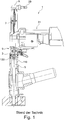
- Fig. 1 shows a representation of an example of a drilling feed unit 1 according to the prior art.
- the drill feed unit 1 has a drill receptacle 3 for attaching a drill 5 to the drill feed unit 1, and a feed device 7 which is set up to mechanically displace the drill receptacle 3 relative to a housing 9 of the drill feed unit 1 in the axial direction, that is to say in the direction of a longitudinal axis A. .
- an adapter piece 110 is provided here, which can be screwed into the drill receptacle 3 with a threaded connector 130, which for this purpose has an internal thread complementary to an external thread of the threaded connector 130.
- the adapter piece 110 is permanently connected to the drill 5, in particular shrunk onto the drill 5.
- this is cumbersome because an adapter piece 110 must first be shrunk onto each drill to be used, and moreover, it is material-intensive and expensive, since the adapter pieces 110 are disposed of together with the drills 5.
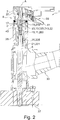
- Fig. 2 shows a detailed representation of an embodiment of a drilling feed unit 1.
- the drill receptacle 3 has an alternating chuck 15.
- the drill 5 is detachably connected to the alternating chuck 15, in particular clamped therein, so that it is possible to replace the drill 5 by removing it from the alternating chuck 15 and thus separating it from the alternating chuck 15, with a new drill 5 subsequently inserted in the alternating chuck 15 and can be clamped there.
- the drill receptacle 3 here has an intermediate piece receptacle 17 and an intermediate piece 11, the intermediate piece 11 being set up to mechanically at a first end 19 with the intermediate piece receptacle 17 and with a second end 21 opposite the first end 19 along the longitudinal axis A. the drill 5 to be connected.
- the intermediate piece 11 is designed as an alternating chuck 15 for releasably fastening the drill 5.
- the intermediate piece 11 is the alternating chuck 15, or in other words: the alternating chuck 15 forms the intermediate piece 11 or is identical to the intermediate piece 11.
- the intermediate piece 11 thus particularly preferably takes the place of the adapter piece 110 known from the prior art, although it can be releasably connected to the drill 5 and is therefore reusable.
- the intermediate piece 11 preferably has a connecting piece 22, here a threaded connector 23 at the first end 19, the threaded connector 23 being set up for screwing on of the intermediate piece 11 to the intermediate piece receptacle 17.
- the threaded connector 23 is designed here as a threaded connector 13.
- the threaded connector 13 is configured analogously to the threaded connector 130 of the known adapter piece 110 and is thus matched to the drill receptacle 3 of a otherwise known drilling feed unit 1, so that the intermediate piece 11 and thus the interchangeable chuck 15 also in the case of existing drilling feed units 1 in Retrofit solution can be used.
- the threaded connector 23 can also be designed as a cylindrical connector with an internal thread, or in another suitable manner.
- this requires a corresponding, complementary configuration of the drill holder 3 or the provision of a suitable adapter.
- the intermediate piece 11 has a clamping receptacle 25 for releasably clamping the drill 5.
- a contact surface 27 is formed on the drilling feed unit 1, which serves to place the drilling feed unit 1 on a workpiece surface in order to be able to drill a hole in the workpiece with high precision.
- the contact surface 27 remains in constant contact with the surface of the workpiece, while the drill 5 is displaced by the feed device 7 relative to the housing 9 and thus at the same time also relative to the contact surface 27.
- the feed device 7 is preferably designed as a pneumatic feed device, with reference to FIG Figure 1 a pneumatic connection 29 is assigned.
- the drill 5 is set in a rotational movement about the longitudinal axis A, in particular the drill receptacle 3 being set in rotation, which takes the drill 5 with it.
- the drill receptacle 3 is in turn related to FIG Figure 1 a motor drive 31 is assigned.
- This can also be a pneumatic drive.
- other drive concepts are possible both for the motor drive 31 and for the feed device 7, for example an electric drive, a hydraulic drive, or any other type of suitable drive.
- manual drive is also conceivable for at least one of the forms of movement.
- the housing 9 also has a suction port 33 which can be fluidically connected to a suction device, not shown here, in order to suck up chips from the area of the resulting bore.
- the chips are preferably conveyed through at least one chip space of the drill 5, which is wound along a helical line, out of the resulting hole in the direction of the suction connection 33.
- the drilling feed unit 1 can be hand-held or attached to a robot arm. Of course, other options for holding and / or guiding the drilling feed unit 1 are also possible. Such a drilling feed unit 1 is used in particular in aircraft construction, there preferably for making rivet holes.
- the housing 9 accommodates the drill receptacle 3 and the feed device 7 here. At the same time encloses the housing 9 at least in the in Figure 2 retracted state of the drill 5 also largely this at least.
- the intermediate piece 11 and thus at the same time the alternating chuck 15 is designed in accordance with a preferred embodiment as a hydraulic chuck.
- the intermediate piece 11 and thus the alternating chuck 15 is particularly preferably designed as a hydraulic chuck in accordance with the technical teaching disclosed in this regard.
- a hydraulic expansion chuck designed in this way enables use even in a confined installation space, such as the interior of the housing 9 of the drilling feed unit 1.
- the intermediate piece 11 and thus also the interchangeable chuck 15 is designed as a collet, as a polygonal chuck, as a surface chuck or in another suitable manner, in particular as another chuck.
- the drill receptacle 3 is preferably arranged at least in regions in a housing section 35 of the housing 9.
- the housing section 35 is in particular a distal housing section, that is to say a housing section which is intended to face a workpiece to be machined.
- the drill receptacle 3 can be displaced in the housing section 35.
- the intermediate piece receptacle 17 is also preferably arranged, at least in regions, and the intermediate piece 11 and the drill 5 in the housing section 35, preferably displaceable therein.
- the housing section 35 is here detachably connected to an upper housing 37 of the housing 9.
- the housing section 35 can be separated from the upper housing 37 in order to replace the drill 5.
- the feed device 7 is arranged in particular in the upper housing 37.
- the separating mechanism 39 here comprises a finger lever 41 which is pressed under spring preload into a locking position and can be displaced against the spring preload into an unlocking position and which can be actuated in a quick and simple manner by a user of the drilling feed unit 1 - in particular with a finger the trigger of a handgun.
- the alternating chuck 15 and thus the intermediate piece 11 are preferably first separated from the drill receptacle 3 and thus from the intermediate piece receptacle 17, in particular by unscrewing, the alternating chuck 15 being removed from the drilling feed unit 1 together with the drill 5.
- the drill 5 is then released from the alternating chuck 15 outside the drilling feed unit 1.
- a new drill 5 is then inserted, in particular clamped, into the alternating chuck 15.
- the alternating chuck 15 is in turn fastened with the new drill 5 to the drill receptacle 3 and at the same time to the intermediate piece receptacle 17, in particular by screwing or screwing it in.
- the housing section 35 is first separated from the upper housing 37, as a result of which the alternating chuck 5 is accessible so that it can be detached from the drill receptacle 3.
- the alternating chuck 15 can also be fastened to the drill receptacle 3 with the new drill 5.
- the housing section 35 is preferably reattached to the upper housing 37 or connected to the upper housing 37.
- the intermediate piece 11 preferably has a maximum width dimension, in particular a maximum outer diameter, of at least 5 mm to at most 40 mm, preferably from at least 7 mm to at most 35 mm, preferably from at least 10 mm to at most 30 mm, preferably from at least 15 mm to at most 20 mm on.
- the width dimension is measured in particular perpendicular to the extension of the longitudinal axis A. In this way, the intermediate piece 11 is dimensioned such that it can be used in the cramped installation space inside the housing 9 of the drilling feed unit 1.
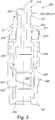
- Fig. 3 shows a representation of an embodiment of a hydraulic chuck 200 in longitudinal section.
- the hydraulic expansion chuck has a clamping receptacle 225 for detachable Clamping a tool.
- the hydraulic expansion chuck 200 has a maximum width dimension, measured perpendicular to a longitudinal axis A ′, of at least 5 mm to at most 40 mm, preferably from at least 7 mm to at most 35 mm, preferably from at least 10 mm to at most 30 mm, preferably from at least 15 mm to at most 20 mm.
- the hydraulic expansion chuck 200 is thus made very small with regard to its maximum width dimension and can therefore also be used in confined installation spaces.
- the maximum width dimension is a maximum outer diameter of the hydraulic expansion chuck 200.
- the longitudinal axis A ′ preferably extends parallel to the longitudinal axis of a tool inserted into the clamping receptacle 225.
- the hydraulic expansion chuck 200 is in particular set up for use as an alternating chuck 15 of a drilling feed unit 1 according to the technical teaching disclosed herein.
- the alternating chuck 15 of the drilling feed unit 1, and consequently also the intermediate piece 11, is the hydraulic expansion chuck 200 disclosed here.
- the longitudinal axis A ′ of the hydraulic expansion chuck 200 is aligned with the longitudinal axis A of the drilling feed unit 1 or coincides with this when the hydraulic expansion chuck 200 inserted into the drilling feed unit 1, in particular on the drill receptacle 3, that is to say in particular the intermediate piece receptacle 17, as an intermediate piece 11.
- the hydraulic expansion chuck 200 and the drilling feed unit 1 can also be used separately from one another.
- the hydraulic expansion chuck 200 can be used in other applications independently of the drilling feed unit 1.
- the drilling feed unit 1 can be used with another alternating chuck, regardless of the hydraulic expansion chuck 200.
- the clamping receptacle 225 has a clamping space 205 enclosed by a clamping wall 203.
- at least one pressure chamber 207 is formed in the tensioning wall 203, which can be filled, preferably filled, with a pressure fluid, in particular a pressure oil.
- a first pressure prevails in the pressure chamber 207, at which an inner surface 209 is elastically deformed into the clamping space 205 starting from a relaxed position, as a result of which a tool, in particular a drill, arranged in regions in the clamping space 205 passes through the deformed inner surface 209 can be tensioned.
- a second functional position of the hydraulic expansion chuck 200 there is a second pressure in the pressure chamber 207 which is lower than the first pressure at which the inner surface 209 is arranged in its relaxed position, so that the inside diameter of the clamping space 205 is larger than in the first functional position, and the tool is released and thus can be removed from the clamping space 205.
- a new tool can be inserted into the clamping space 205 in the second functional position, wherein it can then be clamped from the second functional position into the first functional position by moving the hydraulic expansion chuck 200.
- the basic mode of operation of such a hydraulic expansion chuck 200 is known per se, so that it will not be discussed in more detail here.
- the hydraulic expansion chuck 200 has along its longitudinal axis A 'facing away from the clamping receptacle 225, in particular at a first end 219, a connecting piece 222 for mechanical connection to a receptacle for the hydraulic expansion chuck 200, and also a centering surface 211.
- the centering surface 211 is arranged offset radially outward to the connecting piece 222.
- a radial direction is perpendicular to the longitudinal axis A 'of the hydraulic expansion chuck 200.
- the centering surface 211 is also axially offset from the connecting piece 222, in particular offset in the direction of the clamping receptacle 225.
- the clamping receptacle 225 is arranged at a second end 221 opposite the first end 219 along the longitudinal axis A ′.
- the connecting piece 222 is preferably designed as a threaded connector 223.
- the threaded connector 223 is preferably designed as a threaded connector 213 with an external thread 231.
- the threaded connector 223 can also be designed as a cylinder socket with an internal thread, or in another suitable manner.
- the connecting piece 222 can also be designed in another suitable manner, for example as a clamping stub or in another suitable form.
- the centering surface 211 is preferably designed as a truncated cone surface. It is particularly preferably designed to be complementary to a counter-centering surface 43 of the drill holder 3, in particular the adapter holder 17, of the drilling feed unit 1, so that the hydraulic expansion chuck 200 is centered on the drill holder 3 when the centering surface 211 is in particular in full contact with the counter-centering surface 43.
- the connecting piece 222 serves to axially fix the hydraulic expansion chuck 200 to the drill receptacle 3, the centering surface 211 being used for alignment and centering.
- the counter centering surface 43 is preferably also designed as a truncated cone surface of an inner cone.
- the centering surface 211 is correspondingly the truncated cone surface of an outer cone.
- an exemption 233 is formed between the connecting piece 222 and the centering surface 211.
- the at least one pressure chamber 207 is fluidly connected to at least one pressure cylinder, here with two pressure cylinders 235, 235 '.
- a cylinder longitudinal axis Z of the pressure cylinder 235 encloses an angle of at least 0 ° to at most 3 °, preferably from at least 1 ° to at most 2 °, preferably of 1.5 °, with the longitudinal axis A ′ of the hydraulic expansion chuck 200.
- This preferably applies to each pressure cylinder 235, 235 ', in particular each cylinder longitudinal axis Z of a pressure cylinder 235, 235' enclosing the same angle with the longitudinal axis A 'of the hydraulic expansion chuck 200.
- a pressure piston in each of the pressure cylinders 235, 235 ', can be displaced, the pressure fluid in the pressure chamber 207, which is at least partially also arranged in the pressure cylinders 235, 235', being displaced by displacing the pressure piston along the respective cylinder longitudinal axis Z. can be set or relaxed.
- a pressure screw bore 237, 237 ' is assigned to each pressure cylinder 235, 235'.
- the respective pressure screw bore 237, 237 ' is operatively connected to the associated pressure cylinder 235, 235' for influencing the pressure of a pressure of the pressure fluid in the pressure cylinder 235, 235 'and thus also in the pressure chamber 207.
- a pressure screw not shown here, is arranged in the pressure screw bore 237, 237 ', the respective pressure cylinder being displaceable in the direction of the respective cylinder longitudinal axis Z by screwing in or unscrewing the pressure screw.
- the pressure screw is designed as a grub screw and preferably has an actuating engagement, in particular an internal hexagon engagement.
- the longitudinal axis B of the bore is offset perpendicularly to the cylinder axis Z, in particular offset radially inward in the direction of the longitudinal axis A 'of the hydraulic expansion chuck 200. This allows a particularly space-saving design - in particular in the width direction - of the hydraulic expansion chuck 200.
- the pressure screws typically have a diameter that is larger than the diameter of the pressure pistons, so that the pressure screw holes 237, 237 'also have a larger diameter than the pressure cylinder 235, 235 '.
- the pressure chamber 207 is preferably fluidly connected to a plurality of pressure cylinders 235, 235 '.
- the volume displacement and pressure increase in the pressure chamber for the first functional position can then be brought about by displacing a plurality of pressure pistons, as a result of which the axial displacement path for each individual pressure piston becomes smaller when an equal volume displacement and ultimately pressure difference are achieved.
- the fluidic connection of the pressure chamber 207 to a plurality of pressure cylinders 235, 235 ' also contributes to a particularly small installation space for the hydraulic expansion chuck 200.
- the hydraulic expansion chuck 200 can be made shorter - and at the same time smaller due to the angle of the cylinder longitudinal axes Z to the longitudinal axis A 'of the hydraulic expansion chuck 200 - than would be the case if the pressure chamber 207 had only one pressure cylinder 235, 235'. would be fluidically connected.
- the at least one pressure screw bore 237, 237 ' opens into the centering surface 211.
- This enables a particularly compact installation space for the hydraulic expansion chuck 200.
- the pressure screw holes 237, 237 'and thus at the same time the pressure screws are only accessible when the intermediate piece 11 of the Intermediate piece receptacle 17 separated and thus the centering surface 211 is separated from the counter centering surface 43.
- the drill 5 is preferably first separated from the adapter receptacle 17 together with the intermediate piece 11, after which the drill 5 is released from the alternating chuck 15, here the hydraulic expansion chuck 200.
- a new drill 5 can then be clamped in the alternating chuck 15, here the hydraulic expansion chuck 200, wherein the alternating chuck 15 together with the drill 5 can then in turn be fixed to the adapter receptacle 17 and in particular centered over the centering surface 211 and the counter-centering surface 43.
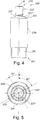
- Fig. 4 shows a side view of the hydraulic chuck 200 according to Figure 3 .
- the hydraulic expansion chuck 200 preferably has a cylindrical, in particular circular-cylindrical outer peripheral surface 239.
- the hydraulic expansion chuck 200 is preferably of fully cylindrical design, in particular except for the area of the connecting piece 222, the centering surface 211, and of key surfaces 241, which are explained in more detail below, of which only one is identified by reference number 241 for the sake of clarity.
- the key surfaces 241 serve in particular to allow a tool, in particular a key, to engage the hydraulic chuck 200 - in particular in the region of the second end 221 - in order to insert the hydraulic chuck 200 with the connecting piece 222 into a receptacle for the hydraulic chuck 200, in particular into the Screw adapter piece 17 of the drilling feed unit 1.
- the hydraulic expansion chuck 200 preferably has more than two pressure cylinders 235, 235 'and correspondingly also more than two pressure screw bores 237, 237', 237 ", in the exemplary embodiment shown here in particular three pressure screw bores 237, 237 ', 237" which extend into the centering surface 211 flow out.
- FIG. 12 shows a view of the hydraulic chuck 200 according to FIGS Figures 3 and 4th from underneath.
- the three pressure screw bores 237, 237 ', 237 can be seen here. These are each arranged here at an angular distance of 90 ° to one another in three quadrants. In the fourth quadrant is accordingly at an angle distance of 90 ° to the immediately adjacent pressure screw bores 237 , 237 'arranged a balancing bore 243.
- FIG. 4 shows a three-dimensional view of the hydraulic chuck 200 according to FIGS Figures 3 to 5 .
- the outer hexagon formed by the key surfaces 241 and the cylindrical outer circumferential surface 239 can be clearly seen here.
- the hydraulic expansion chuck 200 has an insertion chamfer 245 in the region of the second end 221 in the mouth region to the clamping space 205, which also serves as an insertion rounding can be trained.
- the insertion chamfer 245 or insertion rounding makes it easier to insert a workpiece, in particular a drill 5, into the clamping space 205.
- the hydraulic expansion chuck 200 is preferably manufactured additively, particularly preferably by 3D printing, in particular by laser sintering or laser beam melting. In this way, it is particularly easy to design the hydraulic expansion chuck 200 with its geometric features described here.
- the hydraulic expansion chuck 200 preferably also has a central channel 247, via which the clamping space 205 is accessible from the first end 219, in particular through the connecting piece 222.
- This central channel 247 is preferably set up to allow coolant / lubricant to be transported to a tool arranged in the clamping space 205.
Landscapes
- Engineering & Computer Science (AREA)
- Mechanical Engineering (AREA)
- Gripping On Spindles (AREA)
- Earth Drilling (AREA)
Priority Applications (2)
| Application Number | Priority Date | Filing Date | Title |
|---|---|---|---|
| ES18214184T ES3050067T3 (en) | 2018-12-19 | 2018-12-19 | Hydraulic expansion chuck and drill feed unit |
| EP18214184.6A EP3670045B1 (fr) | 2018-12-19 | 2018-12-19 | Mandrin de serrage à extension hydraulique ainsi qu'unité d'avance du forage |
Applications Claiming Priority (1)
| Application Number | Priority Date | Filing Date | Title |
|---|---|---|---|
| EP18214184.6A EP3670045B1 (fr) | 2018-12-19 | 2018-12-19 | Mandrin de serrage à extension hydraulique ainsi qu'unité d'avance du forage |
Publications (2)
| Publication Number | Publication Date |
|---|---|
| EP3670045A1 true EP3670045A1 (fr) | 2020-06-24 |
| EP3670045B1 EP3670045B1 (fr) | 2025-10-01 |
Family
ID=64746244
Family Applications (1)
| Application Number | Title | Priority Date | Filing Date |
|---|---|---|---|
| EP18214184.6A Active EP3670045B1 (fr) | 2018-12-19 | 2018-12-19 | Mandrin de serrage à extension hydraulique ainsi qu'unité d'avance du forage |
Country Status (2)
| Country | Link |
|---|---|
| EP (1) | EP3670045B1 (fr) |
| ES (1) | ES3050067T3 (fr) |
Citations (6)
| Publication number | Priority date | Publication date | Assignee | Title |
|---|---|---|---|---|
| GB833048A (en) * | 1957-04-29 | 1960-04-21 | Alfred Ernest Sykes | Improvements in or relating to chucks |
| US3039443A (en) * | 1958-07-31 | 1962-06-19 | Baldwin Instr Company Ltd | Machine tool feed apparatus |
| DE2007813A1 (de) * | 1970-02-20 | 1971-09-02 | Volkswagenwerk Ag | Bohreinrichtung mit pneumatischer Betätigung |
| US3679219A (en) * | 1970-02-20 | 1972-07-25 | Gordon N Cameron | Hydraulically actuated chuck |
| US4752161A (en) * | 1985-12-16 | 1988-06-21 | The Boeing Company | Hand-held drill with self-advancing bit |
| EP2985099A1 (fr) * | 2013-04-10 | 2016-02-17 | Daishowa Seiki Kabushiki Kaisha | Mandrin hydraulique |
Family Cites Families (1)
| Publication number | Priority date | Publication date | Assignee | Title |
|---|---|---|---|---|
| SE527753C2 (sv) * | 2004-10-21 | 2006-05-30 | Etp Transmission Ab | Hydrauliskt friktionsband med justeringsorgan för mängden tryckmedium |
-
2018
- 2018-12-19 EP EP18214184.6A patent/EP3670045B1/fr active Active
- 2018-12-19 ES ES18214184T patent/ES3050067T3/es active Active
Patent Citations (6)
| Publication number | Priority date | Publication date | Assignee | Title |
|---|---|---|---|---|
| GB833048A (en) * | 1957-04-29 | 1960-04-21 | Alfred Ernest Sykes | Improvements in or relating to chucks |
| US3039443A (en) * | 1958-07-31 | 1962-06-19 | Baldwin Instr Company Ltd | Machine tool feed apparatus |
| DE2007813A1 (de) * | 1970-02-20 | 1971-09-02 | Volkswagenwerk Ag | Bohreinrichtung mit pneumatischer Betätigung |
| US3679219A (en) * | 1970-02-20 | 1972-07-25 | Gordon N Cameron | Hydraulically actuated chuck |
| US4752161A (en) * | 1985-12-16 | 1988-06-21 | The Boeing Company | Hand-held drill with self-advancing bit |
| EP2985099A1 (fr) * | 2013-04-10 | 2016-02-17 | Daishowa Seiki Kabushiki Kaisha | Mandrin hydraulique |
Also Published As
| Publication number | Publication date |
|---|---|
| ES3050067T3 (en) | 2025-12-19 |
| EP3670045B1 (fr) | 2025-10-01 |
Similar Documents
| Publication | Publication Date | Title |
|---|---|---|
| DE3324312C2 (de) | Werkzeugmaschine mit Werkzeugwechselvorrichtung | |
| DE102009026389A1 (de) | Verfahren und Spannvorrichtung zum Einspannen eines Rohlings in einer Bearbeitungsmaschine, insbesondere in einer Fräsmaschine | |
| EP3641986B1 (fr) | Système de serrage ayant une fonction dite de troisième main | |
| DE102010008187A1 (de) | Werkzeug zur spanenden Materialbearbeitung sowie Verfahren zum Ausrichten von Schneideinsätzen in einem solchen Werkzeug | |
| EP1233848B1 (fr) | Tete de pierrage | |
| DE102017000671B4 (de) | Drehfutter und Werkzeugmaschine | |
| DE102018119980A1 (de) | Spann- oder Greifeinrichtung | |
| CH668723A5 (de) | Revolverkopf fuer eine drehmaschine und hierzu passende werkzeughalter. | |
| DE102010006918A1 (de) | Verbindungssystem zum lösbaren Verbinden zweier Bauteile | |
| EP2114601B1 (fr) | Porte-outil | |
| DE102009050701A1 (de) | Spanneinrichtung | |
| DE102009044995B4 (de) | Schneideinsatzträger, Schneideinsatzund drehangetriebenes Schneidwerkzeug | |
| DE102009046037B4 (de) | Spannfutter | |
| EP3670047B1 (fr) | Unité d'avance du forage | |
| EP1660262B1 (fr) | Point d'assemblage d'un outil | |
| DE102013206573A1 (de) | Stepper | |
| EP3670045B1 (fr) | Mandrin de serrage à extension hydraulique ainsi qu'unité d'avance du forage | |
| EP2743017B1 (fr) | Dispositif de serrage rapide d'outil | |
| DE102022213778B3 (de) | Modulares Werkzeug und Verfahren zum Auswerfen eines Einsatzes eines modularen Werkzeugs | |
| DE102018007186A1 (de) | Kombiniertes Spannbackensystem für Drehbackenfutter | |
| DE20207842U1 (de) | Klemmvorrichtung | |
| DE102006008818B4 (de) | Vorrichtung zum Schnellspannen eines Werkzeughalters in einer Aufnahme eines Revolvers einer spanabhebenden Werkzeugmaschine | |
| DE102016102908B4 (de) | Schnittstelle für ein Schneidwerkzeug | |
| DE10116070C1 (de) | Spannfutter | |
| DE102005019136B4 (de) | Vorrichtung zum Schnellspannen eines Werkzeughalters |
Legal Events
| Date | Code | Title | Description |
|---|---|---|---|
| PUAI | Public reference made under article 153(3) epc to a published international application that has entered the european phase |
Free format text: ORIGINAL CODE: 0009012 |
|
| STAA | Information on the status of an ep patent application or granted ep patent |
Free format text: STATUS: THE APPLICATION HAS BEEN PUBLISHED |
|
| AK | Designated contracting states |
Kind code of ref document: A1 Designated state(s): AL AT BE BG CH CY CZ DE DK EE ES FI FR GB GR HR HU IE IS IT LI LT LU LV MC MK MT NL NO PL PT RO RS SE SI SK SM TR |
|
| AX | Request for extension of the european patent |
Extension state: BA ME |
|
| STAA | Information on the status of an ep patent application or granted ep patent |
Free format text: STATUS: REQUEST FOR EXAMINATION WAS MADE |
|
| 17P | Request for examination filed |
Effective date: 20210111 |
|
| RBV | Designated contracting states (corrected) |
Designated state(s): AL AT BE BG CH CY CZ DE DK EE ES FI FR GB GR HR HU IE IS IT LI LT LU LV MC MK MT NL NO PL PT RO RS SE SI SK SM TR |
|
| STAA | Information on the status of an ep patent application or granted ep patent |
Free format text: STATUS: EXAMINATION IS IN PROGRESS |
|
| 17Q | First examination report despatched |
Effective date: 20231017 |
|
| GRAP | Despatch of communication of intention to grant a patent |
Free format text: ORIGINAL CODE: EPIDOSNIGR1 |
|
| STAA | Information on the status of an ep patent application or granted ep patent |
Free format text: STATUS: GRANT OF PATENT IS INTENDED |
|
| INTG | Intention to grant announced |
Effective date: 20250508 |
|
| GRAS | Grant fee paid |
Free format text: ORIGINAL CODE: EPIDOSNIGR3 |
|
| GRAA | (expected) grant |
Free format text: ORIGINAL CODE: 0009210 |
|
| STAA | Information on the status of an ep patent application or granted ep patent |
Free format text: STATUS: THE PATENT HAS BEEN GRANTED |
|
| AK | Designated contracting states |
Kind code of ref document: B1 Designated state(s): AL AT BE BG CH CY CZ DE DK EE ES FI FR GB GR HR HU IE IS IT LI LT LU LV MC MK MT NL NO PL PT RO RS SE SI SK SM TR |
|
| RAP3 | Party data changed (applicant data changed or rights of an application transferred) |
Owner name: MAPAL DR. KRESS SE & CO. KG |
|
| REG | Reference to a national code |
Ref country code: GB Ref legal event code: FG4D Free format text: NOT ENGLISH Ref country code: CH Ref legal event code: F10 Free format text: ST27 STATUS EVENT CODE: U-0-0-F10-F00 (AS PROVIDED BY THE NATIONAL OFFICE) Effective date: 20251001 |
|
| REG | Reference to a national code |
Ref country code: DE Ref legal event code: R096 Ref document number: 502018016130 Country of ref document: DE |
|
| REG | Reference to a national code |
Ref country code: IE Ref legal event code: FG4D Free format text: LANGUAGE OF EP DOCUMENT: GERMAN |
|
| P01 | Opt-out of the competence of the unified patent court (upc) registered |
Free format text: CASE NUMBER: UPC_APP_8887_3670045/2025 Effective date: 20251002 |
|
| REG | Reference to a national code |
Ref country code: ES Ref legal event code: FG2A Ref document number: 3050067 Country of ref document: ES Kind code of ref document: T3 Effective date: 20251219 |
|
| PGFP | Annual fee paid to national office [announced via postgrant information from national office to epo] |
Ref country code: GB Payment date: 20251219 Year of fee payment: 8 |
|
| PGFP | Annual fee paid to national office [announced via postgrant information from national office to epo] |
Ref country code: FR Payment date: 20251229 Year of fee payment: 8 |
|
| PGFP | Annual fee paid to national office [announced via postgrant information from national office to epo] |
Ref country code: TR Payment date: 20251219 Year of fee payment: 8 |
|
| REG | Reference to a national code |
Ref country code: NL Ref legal event code: MP Effective date: 20251001 |
|
| PG25 | Lapsed in a contracting state [announced via postgrant information from national office to epo] |
Ref country code: NL Free format text: LAPSE BECAUSE OF FAILURE TO SUBMIT A TRANSLATION OF THE DESCRIPTION OR TO PAY THE FEE WITHIN THE PRESCRIBED TIME-LIMIT Effective date: 20251001 |
|
| PGFP | Annual fee paid to national office [announced via postgrant information from national office to epo] |
Ref country code: ES Payment date: 20260130 Year of fee payment: 8 |
|
| REG | Reference to a national code |
Ref country code: LT Ref legal event code: MG9D |
|
| PG25 | Lapsed in a contracting state [announced via postgrant information from national office to epo] |
Ref country code: NO Free format text: LAPSE BECAUSE OF FAILURE TO SUBMIT A TRANSLATION OF THE DESCRIPTION OR TO PAY THE FEE WITHIN THE PRESCRIBED TIME-LIMIT Effective date: 20260101 |
|
| PGFP | Annual fee paid to national office [announced via postgrant information from national office to epo] |
Ref country code: DE Payment date: 20260129 Year of fee payment: 8 |
|
| PG25 | Lapsed in a contracting state [announced via postgrant information from national office to epo] |
Ref country code: HR Free format text: LAPSE BECAUSE OF FAILURE TO SUBMIT A TRANSLATION OF THE DESCRIPTION OR TO PAY THE FEE WITHIN THE PRESCRIBED TIME-LIMIT Effective date: 20251001 Ref country code: FI Free format text: LAPSE BECAUSE OF FAILURE TO SUBMIT A TRANSLATION OF THE DESCRIPTION OR TO PAY THE FEE WITHIN THE PRESCRIBED TIME-LIMIT Effective date: 20251001 |
|
| PGFP | Annual fee paid to national office [announced via postgrant information from national office to epo] |
Ref country code: IT Payment date: 20260130 Year of fee payment: 8 |
|
| PG25 | Lapsed in a contracting state [announced via postgrant information from national office to epo] |
Ref country code: RS Free format text: LAPSE BECAUSE OF FAILURE TO SUBMIT A TRANSLATION OF THE DESCRIPTION OR TO PAY THE FEE WITHIN THE PRESCRIBED TIME-LIMIT Effective date: 20260101 |
|
| PG25 | Lapsed in a contracting state [announced via postgrant information from national office to epo] |
Ref country code: IS Free format text: LAPSE BECAUSE OF FAILURE TO SUBMIT A TRANSLATION OF THE DESCRIPTION OR TO PAY THE FEE WITHIN THE PRESCRIBED TIME-LIMIT Effective date: 20260201 |
|
| PG25 | Lapsed in a contracting state [announced via postgrant information from national office to epo] |
Ref country code: PT Free format text: LAPSE BECAUSE OF FAILURE TO SUBMIT A TRANSLATION OF THE DESCRIPTION OR TO PAY THE FEE WITHIN THE PRESCRIBED TIME-LIMIT Effective date: 20260202 Ref country code: CZ Free format text: LAPSE BECAUSE OF FAILURE TO SUBMIT A TRANSLATION OF THE DESCRIPTION OR TO PAY THE FEE WITHIN THE PRESCRIBED TIME-LIMIT Effective date: 20251001 |
|
| PG25 | Lapsed in a contracting state [announced via postgrant information from national office to epo] |
Ref country code: PL Free format text: LAPSE BECAUSE OF FAILURE TO SUBMIT A TRANSLATION OF THE DESCRIPTION OR TO PAY THE FEE WITHIN THE PRESCRIBED TIME-LIMIT Effective date: 20251001 |
|
| PG25 | Lapsed in a contracting state [announced via postgrant information from national office to epo] |
Ref country code: LV Free format text: LAPSE BECAUSE OF FAILURE TO SUBMIT A TRANSLATION OF THE DESCRIPTION OR TO PAY THE FEE WITHIN THE PRESCRIBED TIME-LIMIT Effective date: 20251001 |