EP3670055A1 - Joint soudé à l'arc de filet de recouvrement - Google Patents
Joint soudé à l'arc de filet de recouvrement Download PDFInfo
- Publication number
- EP3670055A1 EP3670055A1 EP18845781.6A EP18845781A EP3670055A1 EP 3670055 A1 EP3670055 A1 EP 3670055A1 EP 18845781 A EP18845781 A EP 18845781A EP 3670055 A1 EP3670055 A1 EP 3670055A1
- Authority
- EP
- European Patent Office
- Prior art keywords
- weld metal
- steel sheet
- point
- fillet arc
- lap fillet
- Prior art date
- Legal status (The legal status is an assumption and is not a legal conclusion. Google has not performed a legal analysis and makes no representation as to the accuracy of the status listed.)
- Granted
Links
Images



Classifications
-
- F—MECHANICAL ENGINEERING; LIGHTING; HEATING; WEAPONS; BLASTING
- F16—ENGINEERING ELEMENTS AND UNITS; GENERAL MEASURES FOR PRODUCING AND MAINTAINING EFFECTIVE FUNCTIONING OF MACHINES OR INSTALLATIONS; THERMAL INSULATION IN GENERAL
- F16B—DEVICES FOR FASTENING OR SECURING CONSTRUCTIONAL ELEMENTS OR MACHINE PARTS TOGETHER, e.g. NAILS, BOLTS, CIRCLIPS, CLAMPS, CLIPS OR WEDGES; JOINTS OR JOINTING
- F16B5/00—Joining sheets or plates, e.g. panels, to one another or to strips or bars parallel to them
- F16B5/08—Joining sheets or plates, e.g. panels, to one another or to strips or bars parallel to them by means of welds or the like
-
- B—PERFORMING OPERATIONS; TRANSPORTING
- B23—MACHINE TOOLS; METAL-WORKING NOT OTHERWISE PROVIDED FOR
- B23K—SOLDERING OR UNSOLDERING; WELDING; CLADDING OR PLATING BY SOLDERING OR WELDING; CUTTING BY APPLYING HEAT LOCALLY, e.g. FLAME CUTTING; WORKING BY LASER BEAM
- B23K9/00—Arc welding or cutting
- B23K9/02—Seam welding; Backing means; Inserts
- B23K9/0216—Seam profiling, e.g. weaving, multilayer
-
- B—PERFORMING OPERATIONS; TRANSPORTING
- B23—MACHINE TOOLS; METAL-WORKING NOT OTHERWISE PROVIDED FOR
- B23K—SOLDERING OR UNSOLDERING; WELDING; CLADDING OR PLATING BY SOLDERING OR WELDING; CUTTING BY APPLYING HEAT LOCALLY, e.g. FLAME CUTTING; WORKING BY LASER BEAM
- B23K9/00—Arc welding or cutting
- B23K9/02—Seam welding; Backing means; Inserts
-
- B—PERFORMING OPERATIONS; TRANSPORTING
- B23—MACHINE TOOLS; METAL-WORKING NOT OTHERWISE PROVIDED FOR
- B23K—SOLDERING OR UNSOLDERING; WELDING; CLADDING OR PLATING BY SOLDERING OR WELDING; CUTTING BY APPLYING HEAT LOCALLY, e.g. FLAME CUTTING; WORKING BY LASER BEAM
- B23K35/00—Rods, electrodes, materials, or media, for use in soldering, welding, or cutting
- B23K35/22—Rods, electrodes, materials, or media, for use in soldering, welding, or cutting characterised by the composition or nature of the material
- B23K35/24—Selection of soldering or welding materials proper
- B23K35/30—Selection of soldering or welding materials proper with the principal constituent melting at less than 1550°C
-
- B—PERFORMING OPERATIONS; TRANSPORTING
- B23—MACHINE TOOLS; METAL-WORKING NOT OTHERWISE PROVIDED FOR
- B23K—SOLDERING OR UNSOLDERING; WELDING; CLADDING OR PLATING BY SOLDERING OR WELDING; CUTTING BY APPLYING HEAT LOCALLY, e.g. FLAME CUTTING; WORKING BY LASER BEAM
- B23K9/00—Arc welding or cutting
- B23K9/23—Arc welding or cutting taking account of the properties of the materials to be welded
-
- C—CHEMISTRY; METALLURGY
- C22—METALLURGY; FERROUS OR NON-FERROUS ALLOYS; TREATMENT OF ALLOYS OR NON-FERROUS METALS
- C22C—ALLOYS
- C22C38/00—Ferrous alloys, e.g. steel alloys
- C22C38/14—Ferrous alloys, e.g. steel alloys containing titanium or zirconium
-
- B—PERFORMING OPERATIONS; TRANSPORTING
- B23—MACHINE TOOLS; METAL-WORKING NOT OTHERWISE PROVIDED FOR
- B23K—SOLDERING OR UNSOLDERING; WELDING; CLADDING OR PLATING BY SOLDERING OR WELDING; CUTTING BY APPLYING HEAT LOCALLY, e.g. FLAME CUTTING; WORKING BY LASER BEAM
- B23K2101/00—Articles made by soldering, welding or cutting
- B23K2101/006—Vehicles
-
- B—PERFORMING OPERATIONS; TRANSPORTING
- B23—MACHINE TOOLS; METAL-WORKING NOT OTHERWISE PROVIDED FOR
- B23K—SOLDERING OR UNSOLDERING; WELDING; CLADDING OR PLATING BY SOLDERING OR WELDING; CUTTING BY APPLYING HEAT LOCALLY, e.g. FLAME CUTTING; WORKING BY LASER BEAM
- B23K2103/00—Materials to be soldered, welded or cut
- B23K2103/02—Iron or ferrous alloys
- B23K2103/04—Steel or steel alloys
Definitions
- the present invention relates to a lap fillet arc welded joint.
- a welded joint having the high strength steel sheets as base materials is included in automotive structural members.
- a lap fillet arc welding method which carries out a fillet arc welding in a state that two high strength steel sheets are overlapped each other is generally used as a method for manufacturing the welded joint.
- the welded joint manufactured by the lap fillet arc welding method is referred to as a lap fillet arc welded joint.
- Structural members used in environments with vibrations and repeated external loads are required to have not only normal static tensile strength but also sufficient fatigue strength in order to withstand forces repeatedly acting.
- the fatigue strength (fatigue limit) of the steel sheet increases in proportion to its tensile strength.
- the fatigue strength of the lap fillet arc welded joint is lower than the fatigue strength of the steel sheet which is a base material of this joint.
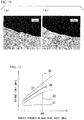
- FIG. 12 is a graph showing the relationship between the fatigue strength (fatigue limit) of the lap fillet arc welded joint and the tensile strength of the base steel sheet, with the shape of the weld toe portion as a parameter.
- the relationship between fatigue strength and tensile strength is referred to as a fatigue characteristic.
- the fatigue characteristic of the base steel sheet alone is also shown as a reference (see straight line C0). As shown by the straight line C0, the fatigue strength of the base steel sheet alone increases in proportion to its tensile strength.
- a curve C1 indicates a fatigue characteristic when the shape of a toe portion of a weld metal is steep
- a curve C2 indicates a fatigue characteristic when the shape of the toe portion of the weld metal is gentle.
- the curve C1 when the shape of the toe portion of the weld metal is steep, even if the tensile strength of the base steel sheet increases, the fatigue strength of the lap fillet arc welded joint hardly increases and only changes at a very low level compared with the fatigue strength of the base steel sheet alone.
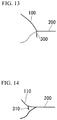
- FIG. 13 is a schematic view of a joint portion between the weld metal 100 having a steep toe shape and the base steel sheet 200 as seen in a cross section orthogonal to a weld line of the weld metal 100.
- Patent Document 1 as a technique for stably controlling the shape of the toe portion of the weld metal into a gentle shape, a technique for improving wettability of molten metal with respect to a base steel sheet by performing a lap fillet arc welding using a welding material (welding wire) having a specific component composition.
- the welding material disclosed in Patent Document 1 contains, by mass%, C: 0.005% to 0.40%, Mn: 0.2% to 8.0%, and Si: more than 1.1% to 8.0%, and further contains Se: 0.01 % to 1% and/or Te: 0.01% to 1%.
- Patent Document 2 a technique is disclosed in which concentration of local stresses and strains due to the difference in hardness occurred near the fusion boundary is reduced by not only controlling the shape of the toe portion of the weld metal into a gentle shape but also controlling the ratio of hardness of the weld metal with respect to hardness of the heat-affected zone within a specific range, in order to improve the fatigue strength of the lap fillet arc welded joint.
- the hardness of the weld metal is the hardness Hv (FL - 0.5) of the weld metal at a position 0.5 mm away from the fusion boundary FL of the weld toe portion toward the weld metal.
- the hardness of the heat-affected zone is the hardness Hv (FL + 0.5) of the heat-affected zone at a position 0.5 mm away from the fusion boundary FL toward the heat-affected zone.
- the ratio (Hv (FL - 0.5) / (FL + 0.5)) of hardness of the weld metal with respect to hardness of the heat-affected zone is controlled within the range of 0.3 to 0.9.
- a technique for controlling the shape of the toe portion of the weld metal into a gentle shape is generally used as a technique for improving the fatigue strength of the lap fillet arc welded joint.
- the curve C2 of FIG. 12 it has been found by researches of the present inventors that when the tensile strength of the base steel sheet is 950 MPa or more, the fatigue strength of the lap fillet arc welded joint is significantly reduced even if the shape of the toe portion of the weld metal is controlled into a gentle shape.
- joint technology welding technology
- the present inventors have investigated reasons why the fatigue strength of the lap fillet arc welded joint is significantly reduced when the tensile strength of the base steel sheet is 950 MPa or more.
- FIG. 14 is a schematic view of a joint portion between the weld metal 110 having the gentle toe shape and the base steel sheet 200 as seen in a cross section orthogonal to a weld line of the weld metal 110.
- the present inventors have microscopically observed the portion where the fatigue crack 310 has occurred, it has been found that the fatigue crack 310 has occurred from coarse ferrite grains present on the surface of the toe portion of the weld metal. Based on the above results, the present inventors have considered as follows the reason why the fatigue strength of the lap fillet arc welded joint is significantly reduced when the tensile strength of the base steel sheet is 950 MPa or more.
- ferrite and bainite are generated on the surface of the weld metal.
- ferrite has a relatively soft structure
- bainite or martensite
- stress and strain tend to concentrate on soft ferrite due to the difference in strength between structures having different hardnesses.
- stress and strain concentrate on the ferrite, and as a result, it is considered that the fatigue crack 310 occurs from ferrite grains present on the surface of the weld metal at an early stage.
- a curve C3 indicates a fatigue characteristic of the lap fillet arc welded joint obtained by performing the lap fillet arc welding using a welding wire having higher strength so that the shape of the toe portion of the weld metal becomes gentle.
- the fatigue strength of the lap fillet arc welded joint continues to increase even if the tensile strength of the base steel sheet is 950 MPa or more.
- the present invention is made in consideration of the above-described circumstances, and an object thereof is to increase the fatigue strength of a lap fillet arc welded joint manufactured by base steel sheets each having a tensile strength of 950 MPa or more without using a high-strength welding wire that causes the hydrogen embrittlement cracks.
- the present invention employs the followings.
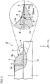
- FIG. 1 is a cross-sectional view of a lap fillet arc welded joint 10 according to the present embodiment.
- FIG. 2 is a plane view of the lap fillet arc welded joint 10 according to the present embodiment.
- the lap fillet arc welded joint 10 according to the present embodiment includes: a first steel sheet 1 and a second steel sheet 2 which are overlapped each other; and a weld metal (weld bead) 3 which extends along a corner 4 formed by an upper surface 1a of the first steel sheet 1 and an end surface 2a of the second steel sheet 2.
- FIG. 1 is a view of the lap fillet arc welded joint 10 as seen in a cross section orthogonal to a weld line W (see FIG. 2 ) of the weld metal 3.
- a direction parallel to the weld line W is defined as a Z-axis direction
- a direction orthogonal to the Z-axis direction and parallel to the upper surface 1a of the first steel sheet 1 is defined as a X-axis direction
- a direction orthogonal to the X-axis direction and the Z-axis direction and parallel to a thickness direction of the first steel sheet 1 is defined as a Y-axis direction.
- Each of the first steel sheet 1 and the second steel sheet 2 is a base steel sheet of the lap fillet arc welded joint 10, and has a tensile strength of 950 MPa or more.
- the first steel sheet 1 and the second steel sheet 2 each having such the high tensile strength are suitable as the base steel sheets of the lap fillet arc welded joint 10 for automobiles that are particularly required to be lighter and to improve collision safety.
- it is preferable that each of the first steel sheet 1 and the second steel sheet 2 has a thickness of 0.8 mm to 3.5 mm.
- the component composition of the first steel sheet 1 and the second steel sheet 2 is not particularly limited as long as a mechanical characteristic of a tensile strength of at least 950 MPa can be obtained.
- each of the first steel sheet 1 and the second steel sheet 2 preferably contains, by mass%, C: 0.01 % to 0.25%, Si: 0.01% to 2.0%, Mn: 0.1% to 3.0%, P: 0.05% or less, and S: 0.0005% to 0.01%.
- the weld metal 3 is a weld bead that is formed by continuously performing the fillet arc welding along the corner 4 in the Z-axis direction in a state that the first steel sheet 1 is overlapped with the second steel sheet 2.
- improvement of the fatigue strength of the lap fillet arc welded joint 10 is realized by controlling the hardness of the weld metal 3, the toe portion shape of the weld metal 3, and the relationship between the surface shape of the weld metal 3 and the ferrite structure so as to satisfy specific conditions respectively.
- the Vickers hardness of the weld metal 3 is 400 HV or less. When the Vickers hardness of the weld metal 3 exceeds 400 HV, hydrogen embrittlement cracks occur in the weld metal 3. In other words, it is possible to suppress the hydrogen embrittlement cracks from occurring in the weld metal 3 by limiting the Vickers hardness of the weld metal 3 to 400 HV or less.
- the Vickers hardness of the weld metal 3 is measured at five points or more along a straight line which is parallel to the X-axis direction and passes through a position at a depth of 0.1 mm from the upper surface 1a of the first steel sheet 1. An average of these measured results is defined as the Vickers hardness of the weld metal 3.
- the weld metal 3 rises from the point A with a toe angle ⁇ and rises from a position closer to the second steel sheet 2 from the point A with a flank angle ⁇ .
- the flank angle ⁇ is generally used as a parameter indicating the toe portion shape of the weld metal 3.
- the toe angle ⁇ is used as a parameter indicating the toe portion shape of the weld metal 3.
- the toe angle ⁇ is defined as described below.
- a position 0.5 mm away from the point A toward the weld metal 3 is defined as a point D.
- an intersection point between a surface of the weld metal 3 and a straight line which passes through the point D and extends in the thickness direction (that is, the Y-axis direction) of the first steel sheet 1 is defined as a point B.
- an angle between a straight line connecting the point A with the point B and a straight line connecting the point A with the point D is defined as the toe angle ⁇ of the weld metal 3.
- the weld metal 3 of the lap fillet arc welded joint 10 satisfies the following conditional expression (1). Since the toe portion shape of the weld metal 3 becomes a gentle shape by satisfying the conditional expression (1), it is possible to suppress stresses from concentrating at the toe portion of the weld metal 3. In a case that the toe angle ⁇ is 30° or more, since the toe portion shape of the weld metal 3 becomes a steep shape, stresses tend to concentrate at the toe portion of the weld metal 3. 0 ° ⁇ ⁇ ⁇ 30 °
- the upper surface 1a of the first steel sheet 1 and the end surface 2a of the second steel sheet 2 which are included within the weld metal 3 are indicated by dotted lines in order to indicate the position of the corner 4.
- the portions indicated by the dotted lines are dissolved within the weld metal 3. Therefore, for example, as shown in FIG. 3 , even if a cross-sectional photograph of the weld metal 3 is obtained using an optical microscope, it is impossible to observe the portions indicated by the dotted lines.
- a position 0.4 mm away from the point A toward the weld metal 3 is defined as a point C.
- the total number of concave portions present on the surface of the weld metal 3 included within a range between the point A and the point C is defined as NA.
- NA the number of concave portions in contact with ferrite grains having a maximum grain size of 10 ⁇ m or more
- NB the weld metal 3 of the lap fillet arc welded joint 10 satisfies the following conditional expression (2).
- NB / NA ⁇ 0.70 (Here, NA is 20 or more.)
- the first steel sheet 1 and the second steel sheet 2 each having the tensile strength of 950 MPa or more are used as the base steel sheets, it is possible to increase the fatigue strength of the lap fillet arc welded joint 10 by satisfying the conditional expressions (1) and (2) at the same time.
- the conditional expression (2) when NB/NA exceeds 0.70, the number of the concave portions which become the starting points of the fatigue cracks (that is, the number of the concave portions in contact with ferrite grains having a maximum grain size of 10 ⁇ m or more) increases, thereby the fatigue strength of the lap fillet arc welded joint 10 is reduced.
- the lower limit value of NB/NA is theoretically zero, but it is practically difficult to make NB zero. However, the smaller the value of NB/NA, the greater the effect of improving fatigue strength.
- a portion including the weld metal 3 is cut out from the lap fillet arc welded joint 10 as a sample, and then the sample is cut so that a cross section of the weld metal 3 (cross section orthogonal to the weld line W) is exposed.
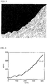
- the cross section of the weld metal 3 included within at least a range of 0.4 mm or less from a fusion boundary (point A) is photographed by an optical microscope, thereby a cross-sectional photograph of the weld metal 3 as shown in FIG. 5 is obtained.
- the optical microscope not only the optical microscope but also a SEM or a microscope may be used as long as a photograph capable of identifying minute unevenness present on the surface of the weld metal 3 can be obtained.
- the cross section of the weld metal 3 included within the range of 0.4 mm or less from the fusion boundary is included in the photograph.
- the surface shape of the weld metal 3 included within a range of 400 ⁇ m or more from the melting boundary is traced with fifty or more plotted points, thereby a point graph representing the macroscopic surface shape of the weld metal 3 as shown in FIG. 6 is created.
- the xy coordinate system composed of the horizontal axis x and the vertical axis y corresponds to the XY coordinate system of FIG. 1 .
- an approximate curve f(x) which is a cubic function representing the macroscopic surface shape of the weld metal 3 is created by the least square method.
- a normal line is drawn from each traced point to the approximate curve f(x), and the length of each normal line is obtained as yi.
- the length yi of each normal line is obtained by the following expression (3).
- a minus sign is attached to the length yi of the normal line of the point located below the approximate curve f(x).
- the right side min ( ) of the expression (3) means the minimum value in parentheses, and can be obtained by convergence calculation or the like.
- the length of the approximate curve f(x) from the intersection of the normal line and the approximate curve f(x) to the fusion boundary is determined as xi.
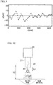
- a point graph representing the unevenness present on the surface of the weld metal 3 as shown in FIG. 9 is created.
- a portion where the y-axis value becomes a minimum value is a concave portion present on the surface of the weld metal 3 included within a range of 0.4 mm from the fusion boundary (point A).
- the NA is calculated by counting the number of the concave portions.
- the number of the concave portions in contact with the ferrite grains having a maximum grain size of 10 ⁇ m or more is counted, thereby the NB is calculated.
- the maximum grain size of the ferrite grain is defined as a length of the longest straight line that can be drawn from an end point located on the surface of the weld metal 3 within the ferrite grain.
- the wording "the concave portion in contact with the ferrite grain” means that at least a portion of the ferrite grain present on the surface of the weld metal 3 included within a range of the x coordinate ⁇ 10 ⁇ m from the minimum value of the point graph shown in FIG. 9 .
- the NA and NB included in the conditional expression (2) can be specified by the above method.
- the NA In order to reliably obtain the effect of improving the fatigue strength by the conditional expression (2), the NA needs to be 20 or more. However, this does not mean that the NA obtained from one cross-sectional photograph must be 20 or more.
- the NA obtained from a plurality of cross-sectional photographs taken at different positions along the weld line W may be 20 or more in total.
- it is also necessary to calculate NB from the plurality of cross-sectional photographs For example, when the NA obtained from the two cross-sectional photographs is 20 or more in total, the total value of the NB obtained from the first cross-sectional photograph and the NB obtained from the second cross-sectional photograph is used as a final value of NB.
- the lap fillet arc welded joint 10 having the weld metal 3 which satisfies the conditional expressions (1) and (2) at the same time, even when the first steel sheet 1 and the second steel sheet 2 each having the tensile strength of 950 MPa or more are used as base materials, improvement of the fatigue strength can be realized. Additionally, since the Vickers hardness of the weld metal 3 is a hardness capable of suppressing hydrogen embrittlement cracks from occurring, the overall strength of the lap fillet arc welded joint 10 can be also prevented from being reduced due to hydrogen embrittlement cracks.
- the ratio of the Vickers hardness of the weld metal 3 to the Vickers hardness of the base steel sheet (first steel sheet 1) may be 0.7 or more.
- the hardness of the HAZ softened portion is reduced to about 60% with respect to the hardness of the base material.
- the Vickers hardness of the first steel sheet 1 is measured at five points or more along a straight line which is parallel to the X-axis direction and passes through a position at a depth of 0.1 mm from the upper surface 1a of the first steel sheet 1. An average of these measured results is defined as the Vickers hardness of the first steel sheet 1.
- the lap fillet arc welded joint 10 according to the present embodiment can be manufactured under the manufacturing conditions described below.
- the Vickers hardness of the weld metal 3 is represented by the following expression (5).
- the weld metal 3 In order to obtain the weld metal 3 with a small amount of coarse ferrite, it is desirable that no ferrite is generated inside the weld metal 3 in the first place. Therefore, in the weld metal 3, it is necessary that the content of Si, Al, Cr, and Mo that are ferrite forming elements is small and the content of Mn, Ni, C, and N that are austenite forming elements is large.
- the weld metal 3 contains, by mass%, Ti: 0.05% to 1.0% and B: 0.0003% to 0.03 %.
- the component of the weld metal 3 is controlled so as to satisfy the above conditions, thereby TiO 2 becomes a transformation nucleus to refine the ferrite, and B segregates at the prior austenite grain boundary to suppress the formation of grain boundary ferrite.
- the weld metal 3 with a small amount of coarse ferrite can be obtained.
- C x C ⁇ 0.92 Si + 0.21 Mn ⁇ 1.15 Al + 0.84 N ⁇ 0.16 Cr + 0.26 Ni ⁇ 0.46 Mo
- a small amount of oxygen is required to realize the refinement of ferrite by intragranular transformation with TiO 2 as the nucleus.
- the shielding gas supplied from the shielding gas nozzle 21 provided at the welding torch 20.
- a small amount of oxygen is mixed into the shielding gas.
- Ar, CO 2 , or a mixed gas of Ar and CO 2 is used as the shielding gas.
- O (oxygen) generated by the ionization of CO 2 in the arc space and oxygen mixed by the entrainment of air affect the oxygen content of the weld metal.
- the curvature radius of the concave portion on the surface of the weld metal is smaller as the surface tension is lower, and is larger as the surface tension is higher.
- a concave portion having a lower surface tension and a smaller curvature radius is more likely to be a starting point of a fatigue crack, and a concave portion having a larger curvature radius is less likely to be a starting point of a fatigue crack. Therefore, the ratio of ferrite grains having a maximum grain size of 10 ⁇ m or more in contact with the concave portions becomes important. When the curvature radius of the concave portion is 13 ⁇ m or less, it tends to be the starting point of the fatigue crack.
- Oxygen mixed in the shielding gas affects the surface tension of the molten pool. In that sense as well, it is important to control the amount of oxygen mixed in the shielding gas within an optimal range.
- a distance L1 is 5 mm to 20 mm and a distance L2 is 8 mm to 30 mm.
- the distance L1 is a distance (wire protrusion length) from the tip of the shield gas nozzle 21 to the tip of the welding wire 22.
- the distance L2 is a distance between the surface of the base material and the contact chip 23 for flowing an electric current through the welding wire 22.
- L2 - L1 ⁇ 1 mm When L2 - L1 ⁇ 1 mm, many concave portions having a depth exceeding 10 ⁇ m are formed, thereby fatigue cracks starting from the concave portions are likely to occur.
- the shielding performance around the arc deteriorates, thereby excessive oxygen is mixed.
- Oxygen content of the weld metal 3 increases and a large amount of oxide precipitates, thereby coarse ferrite such as grain boundary ferrite tends to be generated due to a decrease in the hardenability of the weld metal 3.
- the contact chip 23 may be burned out or the welding torch 20 may be damaged due to fume and spatter adhesion.
- the welding speed is set to 60 to 150 cm/min, and the welding current is set to 150 to 250 A.
- the lap fillet arc welded joint 10 according to the present embodiment can be manufactured under the manufacturing conditions as described above. In this case, the following two conditions are required for the welding wire.
- a relatively low-strength welding wire can be used as a welding wire for manufacturing the lap fillet arc welding joint 10, it is not necessary to use a high-strength welding wire that causes hydrogen embrittlement cracks.
- a high-strength welding wire having a weld metal strength of 950 MPa or more.
- a welding wire having a weld metal strength of 540 MPa or more can be used, not only an increase in the manufacturing cost of the lap fillet arc welded joint 10 can be suppressed but also the occurrence of hydrogen embrittlement cracks due to the strengthening of the weld metal 3 can be suppressed.
- each of the three types of steel sheets was a steel sheet having a thickness of 2.9 mm and a tensile strength of 956 MPa.
- No. A of the welding wire had a component composition satisfying two conditions required for manufacturing the lap fillet arc welded joint of the present invention.
- No. B of the welding wire was a comparative welding wire and did not have a component composition satisfying the two required conditions.
- Component composition (mass%) C Si Mn P S Al Ti B 1 0.14 1.2 2 0.01 0.001 0.03 0.12 0 2 0.08 1.3 2.2 0.01 0.001 0.03 0.1 0 3 0.1 0.8 1.2 0.01 0.001 0.3 0.13 0.002 [Table 2]
- Weld wire No. Component composition (mass%) C Si Mn P S Al Ti B Cr Ni Mo A 0.05 0.5 1.6 0.01 0.01 0.002 0.08 0.004 0.04 0.01 0.01 B 0.06 0.6 1.4 0.01 0.01 0.002 0 0 0.03 0.01 0.01
- Example 1 a lap fillet arc welded joint of Example 1 (test code 1-A-WC1) was obtained by performing the lap fillet arc welding using No. A of the welding wire under the welding condition WC1. Additionally, No. 1 of the steel sheet was used as a base material, and a lap fillet arc welded joint of Comparative Example 1 (test code 1-B-WC1) was obtained by performing the lap fillet arc welding using No. B of the welding wire under the welding condition WC1.
- the welding speed was set to 80 cm/min
- the welding current was set to 235 A
- the wire protrusion length L1 was set to 10 mm
- the distance L2 between the contact chip and the base material was set to 20 mm
- a mixed gas of Ar and 20% CO 2 was used as a shielding gas.
- Example 2 No. 2 of the steel sheet was used as a base material, and a lap fillet arc welded joint of Example 2 (test code 2-A-WC1) was obtained by performing the lap fillet arc welding using No. A of the welding wire under the welding condition WC1. Additionally, No. 2 of the steel sheet was used as a base material, and a lap fillet arc welded joint of Comparative Example 2 (test code 2-B-WC1) was obtained by performing the lap fillet arc welding using No. B of the welding wire under the welding condition WC1.
- Example 3 No. 3 of the steel sheet was used as a base material, and a lap fillet arc welded joint of Example 3 (test code 3-A-WC1) was obtained by performing the lap fillet arc welding using No. A of the welding wire under the welding condition WC1. Additionally, No. 3 of the steel sheet was used as a base material, and a lap fillet arc welded joint of Comparative Example 3 (test code 3-B-WC1) was obtained by performing the lap fillet arc welding using No. B of the welding wire under the welding condition WC1.
- the welding speed was set to 160 cm/min
- the welding current was set to 270 A
- the wire protrusion length L1 was set to 10 mm
- the distance L2 between the contact chip and the base material was set to 20 mm
- a mixed gas of Ar and 20% CO 2 was used as a shielding gas.
- the welding speed was set to 80 cm/min
- the welding current was set to 235 A
- the wire protrusion length L1 was set to 25 mm
- the distance L2 between the contact chip and the base material was set to 35 mm
- a mixed gas of Ar and 20% CO 2 was used as a shielding gas.
- Welding speed (cm/min) Welding current (A) L1 (mm) L2 (mm) Shielding gas WC1 80 235 10 20 Ar+20%CO 2 WC2 160 270 10 20 Ar+20%CO 2 WC3 80 235 25 35 Ar+20%CO 2
- samples for observing the cross section of the weld metal were collected from each of the lap fillet arc welded joints of Examples and Comparative Examples. Then the toe angle ⁇ of the weld metal, the Vickers hardness Hmax of the weld metal, the total number NA of the concave portions present on the surface of the weld metal included within a range of 0.4 mm or less from the fusion boundary, and the number NB of the concave portions in contact with the ferrite grains having a maximum grain size of 10 ⁇ m or more, were respectively measured. Furthermore, samples for fatigue test were collected from each of the lap fillet arc welded joints of Examples and Comparative Examples.
- Examples 1 to 3 satisfied all of the following manufacturing conditions for obtaining the lap fillet arc welded joint of the present invention.
- Comparative Examples 1 to 3 since the manufacturing condition (b) was not satisfied, many coarse ferrite grains were generated on the surface of the weld metal. As a result, it was considered that the value of NB/NA had exceeded 0.70. Therefore, it was considered that the fatigue strengths of Comparative Examples 1 to 3 were lower than those of Examples 1 to 3. In other words, according to the lap fillet arc welded joint not having the above feature (C), it had been demonstrated that the improvement effect of the fatigue strength could not be sufficiently obtained.
- Comparative Example 4 since the manufacturing condition (d) was not satisfied, it was considered that the toe angle ⁇ of the weld metal was 30° or more. Therefore, the shape of the toe portion of the weld metal became steep and stress was concentrated on the toe portion. As a result, it was considered that the fatigue strength of Comparative Example 4 was lower than those of Examples 1 to 3. Additionally, the fatigue strength of Comparative Example 4 was low even when compared with Comparative Example 1 where the toe shape was gentle (the toe angle ⁇ was less than 30°). In other words, according to the lap fillet arc welded joint not having the above feature (B), it had been demonstrated that the improvement effect of the fatigue strength could not be sufficiently obtained.
- Comparative Examples 5 to 7 since the manufacturing condition (c) was not satisfied, a lot of oxygen was mixed in the shield gas, thereby many coarse ferrite grains were formed on the surface of the weld metal. As a result, it was considered that the value of NB/NA had exceeded 0.70. Therefore, it was considered that the fatigue strengths of Comparative Examples 5 to 7 were lower than those of Examples 1 to 3. In other words, in order to obtain the above feature (C), it had been demonstrated that it was necessary not only to control the component composition of the weld metal but also to appropriately control the amount of oxygen mixed into the shield gas.
- FIG. 11 (a) shows a cross-sectional photograph of the vicinity of the toe portion of the weld metal in Example 1.
- FIG. 11(b) shows a cross-sectional photograph of the vicinity of the toe portion of the weld metal in Comparative Example 1. In Example 1, it was appeared that the ferrite in the vicinity of the fusion boundary was refined.
- strain concentration does not occur in the ferrite that becomes the starting point of the fatigue crack and is present on the surface of the weld metal. Therefore, the fatigue limit of the welded joint becomes good, and the fatigue life can be extended. Additionally, there is no concern about hydrogen embrittlement of the joint. As a result, by applying the present invention to automotive underbody members and building materials, safety and durability can be improved, and the great industrial contribution can be obtained.
Landscapes
- Engineering & Computer Science (AREA)
- Mechanical Engineering (AREA)
- Chemical & Material Sciences (AREA)
- Physics & Mathematics (AREA)
- Plasma & Fusion (AREA)
- Materials Engineering (AREA)
- General Engineering & Computer Science (AREA)
- Metallurgy (AREA)
- Organic Chemistry (AREA)
- Butt Welding And Welding Of Specific Article (AREA)
- Arc Welding In General (AREA)
Applications Claiming Priority (2)
| Application Number | Priority Date | Filing Date | Title |
|---|---|---|---|
| JP2017157961 | 2017-08-18 | ||
| PCT/JP2018/030694 WO2019035490A1 (fr) | 2017-08-18 | 2018-08-20 | Joint soudé à l'arc de filet de recouvrement |
Publications (3)
| Publication Number | Publication Date |
|---|---|
| EP3670055A1 true EP3670055A1 (fr) | 2020-06-24 |
| EP3670055A4 EP3670055A4 (fr) | 2021-07-21 |
| EP3670055B1 EP3670055B1 (fr) | 2022-07-13 |
Family
ID=65361857
Family Applications (1)
| Application Number | Title | Priority Date | Filing Date |
|---|---|---|---|
| EP18845781.6A Active EP3670055B1 (fr) | 2017-08-18 | 2018-08-20 | Joint soudé à l'arc de filet de recouvrement |
Country Status (9)
| Country | Link |
|---|---|
| US (1) | US11592045B2 (fr) |
| EP (1) | EP3670055B1 (fr) |
| JP (1) | JP6515401B1 (fr) |
| KR (1) | KR102244232B1 (fr) |
| CN (1) | CN112203792B (fr) |
| BR (1) | BR112020002088A2 (fr) |
| CA (1) | CA3072156A1 (fr) |
| MX (1) | MX2020001540A (fr) |
| WO (1) | WO2019035490A1 (fr) |
Cited By (2)
| Publication number | Priority date | Publication date | Assignee | Title |
|---|---|---|---|---|
| EP4578977A4 (fr) * | 2022-09-28 | 2025-12-10 | Jfe Steel Corp | Joint de soudure et son procédé de fabrication |
| EP4578976A4 (fr) * | 2022-09-28 | 2025-12-10 | Jfe Steel Corp | Joint de soudure et procédé de production associé |
Families Citing this family (6)
| Publication number | Priority date | Publication date | Assignee | Title |
|---|---|---|---|---|
| EP4039396A4 (fr) * | 2019-10-04 | 2022-12-14 | Nippon Steel Corporation | Joint soudé et composant d'automobile |
| JP7376779B2 (ja) * | 2019-11-07 | 2023-11-09 | 日本製鉄株式会社 | 溶接継手、及び自動車部品 |
| KR102428825B1 (ko) * | 2020-12-18 | 2022-08-02 | 주식회사 포스코 | 용접부의 피로강도가 우수한 용접부재 및 그 제조방법 |
| JP7568920B2 (ja) * | 2021-01-04 | 2024-10-17 | 日本製鉄株式会社 | 溶接継手、及び自動車部材 |
| MX2023012392A (es) * | 2021-04-28 | 2023-11-06 | Jfe Steel Corp | Union soldada por arco y metodo de soldadura por arco. |
| JP7715988B2 (ja) * | 2021-09-14 | 2025-07-31 | 日本製鉄株式会社 | アーク溶接継手、溶接構造体及びそれらの製造方法 |
Family Cites Families (13)
| Publication number | Priority date | Publication date | Assignee | Title |
|---|---|---|---|---|
| JPH1161275A (ja) | 1997-08-07 | 1999-03-05 | Mitsubishi Heavy Ind Ltd | オーステナイト系ステンレス鋼の溶接部 |
| JP4736193B2 (ja) * | 2001-01-29 | 2011-07-27 | Jfeスチール株式会社 | 疲労特性に優れるすみ肉溶接継手およびガスシールドアークすみ肉溶接方法 |
| JP3860438B2 (ja) | 2001-03-29 | 2006-12-20 | 株式会社神戸製鋼所 | 溶接継手部の疲労強度に優れた鉄系消耗溶接材料および溶接継手 |
| JP5000476B2 (ja) | 2006-12-25 | 2012-08-15 | 新日本製鐵株式会社 | 耐疲労き裂発生特性に優れた隅肉溶接継手 |
| JP5310350B2 (ja) | 2008-07-23 | 2013-10-09 | 新日鐵住金株式会社 | 疲労特性に優れる重ねすみ肉アーク溶接継手およびその製造方法 |
| JP2011062718A (ja) | 2009-09-16 | 2011-03-31 | Nippon Steel Corp | 薄鋼板の重ねすみ肉アーク溶接継手およびその製造方法 |
| JP5450293B2 (ja) * | 2010-07-01 | 2014-03-26 | 株式会社神戸製鋼所 | すみ肉溶接継手およびガスシールドアーク溶接方法 |
| JP5600652B2 (ja) | 2011-09-27 | 2014-10-01 | 株式会社神戸製鋼所 | 異種金属接合方法 |
| JP5909143B2 (ja) | 2012-04-13 | 2016-04-26 | 株式会社神戸製鋼所 | 熱延鋼板のmag溶接方法および熱延鋼板のmig溶接方法 |
| EP2926939B1 (fr) * | 2012-11-29 | 2017-11-15 | Nippon Steel & Sumitomo Metal Corporation | Procédé de formation de joint de soudage à l'arc d'angle et joint de soudage à l'arc d'angle |
| JP6816355B2 (ja) | 2015-12-03 | 2021-01-20 | 日本製鉄株式会社 | 熱延鋼板およびその製造方法 |
| JP2017157961A (ja) | 2016-02-29 | 2017-09-07 | パナソニック株式会社 | アンテナ基板 |
| US11235415B2 (en) | 2017-02-28 | 2022-02-01 | Nippon Steel Corporation | Fillet welded joint and method of manufacturing thereof |
-
2018
- 2018-08-20 WO PCT/JP2018/030694 patent/WO2019035490A1/fr not_active Ceased
- 2018-08-20 BR BR112020002088-5A patent/BR112020002088A2/pt not_active Application Discontinuation
- 2018-08-20 US US16/636,788 patent/US11592045B2/en active Active
- 2018-08-20 CN CN201880052656.4A patent/CN112203792B/zh active Active
- 2018-08-20 EP EP18845781.6A patent/EP3670055B1/fr active Active
- 2018-08-20 JP JP2018563187A patent/JP6515401B1/ja active Active
- 2018-08-20 KR KR1020207004668A patent/KR102244232B1/ko active Active
- 2018-08-20 CA CA3072156A patent/CA3072156A1/fr not_active Abandoned
- 2018-08-20 MX MX2020001540A patent/MX2020001540A/es unknown
Cited By (2)
| Publication number | Priority date | Publication date | Assignee | Title |
|---|---|---|---|---|
| EP4578977A4 (fr) * | 2022-09-28 | 2025-12-10 | Jfe Steel Corp | Joint de soudure et son procédé de fabrication |
| EP4578976A4 (fr) * | 2022-09-28 | 2025-12-10 | Jfe Steel Corp | Joint de soudure et procédé de production associé |
Also Published As
| Publication number | Publication date |
|---|---|
| KR102244232B1 (ko) | 2021-04-26 |
| CA3072156A1 (fr) | 2019-02-21 |
| CN112203792A (zh) | 2021-01-08 |
| WO2019035490A1 (fr) | 2019-02-21 |
| BR112020002088A2 (pt) | 2020-07-28 |
| EP3670055A4 (fr) | 2021-07-21 |
| JP6515401B1 (ja) | 2019-05-22 |
| KR20200033287A (ko) | 2020-03-27 |
| MX2020001540A (es) | 2020-07-13 |
| CN112203792B (zh) | 2022-03-18 |
| JPWO2019035490A1 (ja) | 2019-11-07 |
| EP3670055B1 (fr) | 2022-07-13 |
| US11592045B2 (en) | 2023-02-28 |
| US20200378420A1 (en) | 2020-12-03 |
Similar Documents
| Publication | Publication Date | Title |
|---|---|---|
| EP3670055B1 (fr) | Joint soudé à l'arc de filet de recouvrement | |
| EP3431220B1 (fr) | Assemblage à recouvrement soudé au laser, son procédé de production et composant de structure d'automobile | |
| EP2116623B1 (fr) | Methode de fabrication d'un tuyau en acier soude par soudage électrique par résistance avant traitement thermique | |
| KR102266643B1 (ko) | 겹치기 필렛 아크 용접 이음매 및 그 제조 방법 | |
| JP4528089B2 (ja) | 耐脆性破壊発生特性を有する船体用大入熱突合せ溶接継手 | |
| EP3797922A1 (fr) | Joint de recouvrement soudé au laser, procédé de production de joint de recouvrement soudé au laser et élément structural pour véhicule | |
| JP5000476B2 (ja) | 耐疲労き裂発生特性に優れた隅肉溶接継手 | |
| EP3862123B1 (fr) | Structure assemblée et procédé de fabrication d'une structure assemblée | |
| JP6299702B2 (ja) | 自動車用骨格部品および自動車用骨格部品の製造方法 | |
| EP4039396A1 (fr) | Joint soudé et composant d'automobile | |
| JP7376779B2 (ja) | 溶接継手、及び自動車部品 | |
| CN100537108C (zh) | 抗脆性断裂发生特性优良的大线能量对接焊接接头 | |
| JP5606741B2 (ja) | テーラードブランクの製造方法およびテーラードブランク用鋼板 | |
| JP7758258B1 (ja) | レーザ溶接継手およびその製造方法 | |
| EP3797921B1 (fr) | Joint de recouvrement soudé au laser, procédé de production d'un joint de recouvrement soudé au laser, et élément structural pour véhicule à moteur | |
| JPWO2020241500A1 (ja) | スポット溶接継手、及びスポット溶接継手の製造方法 | |
| JP4660421B2 (ja) | 高疲労強度隅肉溶接継手及びその形成方法 |
Legal Events
| Date | Code | Title | Description |
|---|---|---|---|
| STAA | Information on the status of an ep patent application or granted ep patent |
Free format text: STATUS: THE INTERNATIONAL PUBLICATION HAS BEEN MADE |
|
| PUAI | Public reference made under article 153(3) epc to a published international application that has entered the european phase |
Free format text: ORIGINAL CODE: 0009012 |
|
| STAA | Information on the status of an ep patent application or granted ep patent |
Free format text: STATUS: REQUEST FOR EXAMINATION WAS MADE |
|
| 17P | Request for examination filed |
Effective date: 20200307 |
|
| AK | Designated contracting states |
Kind code of ref document: A1 Designated state(s): AL AT BE BG CH CY CZ DE DK EE ES FI FR GB GR HR HU IE IS IT LI LT LU LV MC MK MT NL NO PL PT RO RS SE SI SK SM TR |
|
| AX | Request for extension of the european patent |
Extension state: BA ME |
|
| DAV | Request for validation of the european patent (deleted) | ||
| DAX | Request for extension of the european patent (deleted) | ||
| A4 | Supplementary search report drawn up and despatched |
Effective date: 20210621 |
|
| RIC1 | Information provided on ipc code assigned before grant |
Ipc: B23K 9/02 20060101AFI20210615BHEP Ipc: B23K 9/23 20060101ALI20210615BHEP Ipc: B23K 35/30 20060101ALI20210615BHEP Ipc: C22C 38/00 20060101ALI20210615BHEP Ipc: C22C 38/14 20060101ALI20210615BHEP Ipc: B23K 101/00 20060101ALN20210615BHEP Ipc: B23K 103/04 20060101ALN20210615BHEP |
|
| GRAP | Despatch of communication of intention to grant a patent |
Free format text: ORIGINAL CODE: EPIDOSNIGR1 |
|
| STAA | Information on the status of an ep patent application or granted ep patent |
Free format text: STATUS: GRANT OF PATENT IS INTENDED |
|
| RIC1 | Information provided on ipc code assigned before grant |
Ipc: B23K 103/04 20060101ALN20210927BHEP Ipc: B23K 101/00 20060101ALN20210927BHEP Ipc: C22C 38/14 20060101ALI20210927BHEP Ipc: C22C 38/00 20060101ALI20210927BHEP Ipc: B23K 35/30 20060101ALI20210927BHEP Ipc: B23K 9/23 20060101ALI20210927BHEP Ipc: B23K 9/02 20060101AFI20210927BHEP |
|
| INTG | Intention to grant announced |
Effective date: 20211021 |
|
| GRAJ | Information related to disapproval of communication of intention to grant by the applicant or resumption of examination proceedings by the epo deleted |
Free format text: ORIGINAL CODE: EPIDOSDIGR1 |
|
| STAA | Information on the status of an ep patent application or granted ep patent |
Free format text: STATUS: REQUEST FOR EXAMINATION WAS MADE |
|
| GRAS | Grant fee paid |
Free format text: ORIGINAL CODE: EPIDOSNIGR3 |
|
| STAA | Information on the status of an ep patent application or granted ep patent |
Free format text: STATUS: GRANT OF PATENT IS INTENDED |
|
| GRAP | Despatch of communication of intention to grant a patent |
Free format text: ORIGINAL CODE: EPIDOSNIGR1 |
|
| INTC | Intention to grant announced (deleted) | ||
| RIC1 | Information provided on ipc code assigned before grant |
Ipc: B23K 103/04 20060101ALN20220302BHEP Ipc: B23K 101/00 20060101ALN20220302BHEP Ipc: C22C 38/14 20060101ALI20220302BHEP Ipc: C22C 38/00 20060101ALI20220302BHEP Ipc: B23K 35/30 20060101ALI20220302BHEP Ipc: B23K 9/23 20060101ALI20220302BHEP Ipc: B23K 9/02 20060101AFI20220302BHEP |
|
| RIC1 | Information provided on ipc code assigned before grant |
Ipc: B23K 103/04 20060101ALN20220317BHEP Ipc: B23K 101/00 20060101ALN20220317BHEP Ipc: C22C 38/14 20060101ALI20220317BHEP Ipc: C22C 38/00 20060101ALI20220317BHEP Ipc: B23K 35/30 20060101ALI20220317BHEP Ipc: B23K 9/23 20060101ALI20220317BHEP Ipc: B23K 9/02 20060101AFI20220317BHEP |
|
| INTG | Intention to grant announced |
Effective date: 20220330 |
|
| GRAA | (expected) grant |
Free format text: ORIGINAL CODE: 0009210 |
|
| STAA | Information on the status of an ep patent application or granted ep patent |
Free format text: STATUS: THE PATENT HAS BEEN GRANTED |
|
| AK | Designated contracting states |
Kind code of ref document: B1 Designated state(s): AL AT BE BG CH CY CZ DE DK EE ES FI FR GB GR HR HU IE IS IT LI LT LU LV MC MK MT NL NO PL PT RO RS SE SI SK SM TR |
|
| REG | Reference to a national code |
Ref country code: CH Ref legal event code: EP |
|
| REG | Reference to a national code |
Ref country code: DE Ref legal event code: R096 Ref document number: 602018037978 Country of ref document: DE |
|
| REG | Reference to a national code |
Ref country code: AT Ref legal event code: REF Ref document number: 1504012 Country of ref document: AT Kind code of ref document: T Effective date: 20220815 |
|
| REG | Reference to a national code |
Ref country code: IE Ref legal event code: FG4D |
|
| REG | Reference to a national code |
Ref country code: LT Ref legal event code: MG9D |
|
| REG | Reference to a national code |
Ref country code: NL Ref legal event code: MP Effective date: 20220713 |
|
| PG25 | Lapsed in a contracting state [announced via postgrant information from national office to epo] |
Ref country code: SE Free format text: LAPSE BECAUSE OF FAILURE TO SUBMIT A TRANSLATION OF THE DESCRIPTION OR TO PAY THE FEE WITHIN THE PRESCRIBED TIME-LIMIT Effective date: 20220713 Ref country code: RS Free format text: LAPSE BECAUSE OF FAILURE TO SUBMIT A TRANSLATION OF THE DESCRIPTION OR TO PAY THE FEE WITHIN THE PRESCRIBED TIME-LIMIT Effective date: 20220713 Ref country code: PT Free format text: LAPSE BECAUSE OF FAILURE TO SUBMIT A TRANSLATION OF THE DESCRIPTION OR TO PAY THE FEE WITHIN THE PRESCRIBED TIME-LIMIT Effective date: 20221114 Ref country code: NO Free format text: LAPSE BECAUSE OF FAILURE TO SUBMIT A TRANSLATION OF THE DESCRIPTION OR TO PAY THE FEE WITHIN THE PRESCRIBED TIME-LIMIT Effective date: 20221013 Ref country code: NL Free format text: LAPSE BECAUSE OF FAILURE TO SUBMIT A TRANSLATION OF THE DESCRIPTION OR TO PAY THE FEE WITHIN THE PRESCRIBED TIME-LIMIT Effective date: 20220713 Ref country code: LV Free format text: LAPSE BECAUSE OF FAILURE TO SUBMIT A TRANSLATION OF THE DESCRIPTION OR TO PAY THE FEE WITHIN THE PRESCRIBED TIME-LIMIT Effective date: 20220713 Ref country code: LT Free format text: LAPSE BECAUSE OF FAILURE TO SUBMIT A TRANSLATION OF THE DESCRIPTION OR TO PAY THE FEE WITHIN THE PRESCRIBED TIME-LIMIT Effective date: 20220713 Ref country code: FI Free format text: LAPSE BECAUSE OF FAILURE TO SUBMIT A TRANSLATION OF THE DESCRIPTION OR TO PAY THE FEE WITHIN THE PRESCRIBED TIME-LIMIT Effective date: 20220713 Ref country code: ES Free format text: LAPSE BECAUSE OF FAILURE TO SUBMIT A TRANSLATION OF THE DESCRIPTION OR TO PAY THE FEE WITHIN THE PRESCRIBED TIME-LIMIT Effective date: 20220713 |
|
| REG | Reference to a national code |
Ref country code: AT Ref legal event code: MK05 Ref document number: 1504012 Country of ref document: AT Kind code of ref document: T Effective date: 20220713 |
|
| PG25 | Lapsed in a contracting state [announced via postgrant information from national office to epo] |
Ref country code: PL Free format text: LAPSE BECAUSE OF FAILURE TO SUBMIT A TRANSLATION OF THE DESCRIPTION OR TO PAY THE FEE WITHIN THE PRESCRIBED TIME-LIMIT Effective date: 20220713 Ref country code: IS Free format text: LAPSE BECAUSE OF FAILURE TO SUBMIT A TRANSLATION OF THE DESCRIPTION OR TO PAY THE FEE WITHIN THE PRESCRIBED TIME-LIMIT Effective date: 20221113 Ref country code: HR Free format text: LAPSE BECAUSE OF FAILURE TO SUBMIT A TRANSLATION OF THE DESCRIPTION OR TO PAY THE FEE WITHIN THE PRESCRIBED TIME-LIMIT Effective date: 20220713 Ref country code: GR Free format text: LAPSE BECAUSE OF FAILURE TO SUBMIT A TRANSLATION OF THE DESCRIPTION OR TO PAY THE FEE WITHIN THE PRESCRIBED TIME-LIMIT Effective date: 20221014 |
|
| REG | Reference to a national code |
Ref country code: CH Ref legal event code: PL |
|
| REG | Reference to a national code |
Ref country code: DE Ref legal event code: R097 Ref document number: 602018037978 Country of ref document: DE |
|
| PG25 | Lapsed in a contracting state [announced via postgrant information from national office to epo] |
Ref country code: SM Free format text: LAPSE BECAUSE OF FAILURE TO SUBMIT A TRANSLATION OF THE DESCRIPTION OR TO PAY THE FEE WITHIN THE PRESCRIBED TIME-LIMIT Effective date: 20220713 Ref country code: RO Free format text: LAPSE BECAUSE OF FAILURE TO SUBMIT A TRANSLATION OF THE DESCRIPTION OR TO PAY THE FEE WITHIN THE PRESCRIBED TIME-LIMIT Effective date: 20220713 Ref country code: MC Free format text: LAPSE BECAUSE OF FAILURE TO SUBMIT A TRANSLATION OF THE DESCRIPTION OR TO PAY THE FEE WITHIN THE PRESCRIBED TIME-LIMIT Effective date: 20220713 Ref country code: LU Free format text: LAPSE BECAUSE OF NON-PAYMENT OF DUE FEES Effective date: 20220820 Ref country code: LI Free format text: LAPSE BECAUSE OF NON-PAYMENT OF DUE FEES Effective date: 20220831 Ref country code: DK Free format text: LAPSE BECAUSE OF FAILURE TO SUBMIT A TRANSLATION OF THE DESCRIPTION OR TO PAY THE FEE WITHIN THE PRESCRIBED TIME-LIMIT Effective date: 20220713 Ref country code: CZ Free format text: LAPSE BECAUSE OF FAILURE TO SUBMIT A TRANSLATION OF THE DESCRIPTION OR TO PAY THE FEE WITHIN THE PRESCRIBED TIME-LIMIT Effective date: 20220713 Ref country code: CH Free format text: LAPSE BECAUSE OF NON-PAYMENT OF DUE FEES Effective date: 20220831 Ref country code: AT Free format text: LAPSE BECAUSE OF FAILURE TO SUBMIT A TRANSLATION OF THE DESCRIPTION OR TO PAY THE FEE WITHIN THE PRESCRIBED TIME-LIMIT Effective date: 20220713 |
|
| REG | Reference to a national code |
Ref country code: BE Ref legal event code: MM Effective date: 20220831 |
|
| PLBE | No opposition filed within time limit |
Free format text: ORIGINAL CODE: 0009261 |
|
| STAA | Information on the status of an ep patent application or granted ep patent |
Free format text: STATUS: NO OPPOSITION FILED WITHIN TIME LIMIT |
|
| PG25 | Lapsed in a contracting state [announced via postgrant information from national office to epo] |
Ref country code: SK Free format text: LAPSE BECAUSE OF FAILURE TO SUBMIT A TRANSLATION OF THE DESCRIPTION OR TO PAY THE FEE WITHIN THE PRESCRIBED TIME-LIMIT Effective date: 20220713 Ref country code: EE Free format text: LAPSE BECAUSE OF FAILURE TO SUBMIT A TRANSLATION OF THE DESCRIPTION OR TO PAY THE FEE WITHIN THE PRESCRIBED TIME-LIMIT Effective date: 20220713 |
|
| 26N | No opposition filed |
Effective date: 20230414 |
|
| GBPC | Gb: european patent ceased through non-payment of renewal fee |
Effective date: 20221013 |
|
| PG25 | Lapsed in a contracting state [announced via postgrant information from national office to epo] |
Ref country code: AL Free format text: LAPSE BECAUSE OF FAILURE TO SUBMIT A TRANSLATION OF THE DESCRIPTION OR TO PAY THE FEE WITHIN THE PRESCRIBED TIME-LIMIT Effective date: 20220713 |
|
| PG25 | Lapsed in a contracting state [announced via postgrant information from national office to epo] |
Ref country code: IE Free format text: LAPSE BECAUSE OF NON-PAYMENT OF DUE FEES Effective date: 20220820 |
|
| PG25 | Lapsed in a contracting state [announced via postgrant information from national office to epo] |
Ref country code: SI Free format text: LAPSE BECAUSE OF FAILURE TO SUBMIT A TRANSLATION OF THE DESCRIPTION OR TO PAY THE FEE WITHIN THE PRESCRIBED TIME-LIMIT Effective date: 20220713 |
|
| PG25 | Lapsed in a contracting state [announced via postgrant information from national office to epo] |
Ref country code: BE Free format text: LAPSE BECAUSE OF NON-PAYMENT OF DUE FEES Effective date: 20220831 |
|
| PG25 | Lapsed in a contracting state [announced via postgrant information from national office to epo] |
Ref country code: GB Free format text: LAPSE BECAUSE OF NON-PAYMENT OF DUE FEES Effective date: 20221013 |
|
| PG25 | Lapsed in a contracting state [announced via postgrant information from national office to epo] |
Ref country code: IT Free format text: LAPSE BECAUSE OF FAILURE TO SUBMIT A TRANSLATION OF THE DESCRIPTION OR TO PAY THE FEE WITHIN THE PRESCRIBED TIME-LIMIT Effective date: 20220713 |
|
| PG25 | Lapsed in a contracting state [announced via postgrant information from national office to epo] |
Ref country code: CY Free format text: LAPSE BECAUSE OF FAILURE TO SUBMIT A TRANSLATION OF THE DESCRIPTION OR TO PAY THE FEE WITHIN THE PRESCRIBED TIME-LIMIT Effective date: 20220713 |
|
| PG25 | Lapsed in a contracting state [announced via postgrant information from national office to epo] |
Ref country code: MK Free format text: LAPSE BECAUSE OF FAILURE TO SUBMIT A TRANSLATION OF THE DESCRIPTION OR TO PAY THE FEE WITHIN THE PRESCRIBED TIME-LIMIT Effective date: 20220713 Ref country code: HU Free format text: LAPSE BECAUSE OF FAILURE TO SUBMIT A TRANSLATION OF THE DESCRIPTION OR TO PAY THE FEE WITHIN THE PRESCRIBED TIME-LIMIT; INVALID AB INITIO Effective date: 20180820 |
|
| PG25 | Lapsed in a contracting state [announced via postgrant information from national office to epo] |
Ref country code: TR Free format text: LAPSE BECAUSE OF FAILURE TO SUBMIT A TRANSLATION OF THE DESCRIPTION OR TO PAY THE FEE WITHIN THE PRESCRIBED TIME-LIMIT Effective date: 20220713 |
|
| PG25 | Lapsed in a contracting state [announced via postgrant information from national office to epo] |
Ref country code: BG Free format text: LAPSE BECAUSE OF FAILURE TO SUBMIT A TRANSLATION OF THE DESCRIPTION OR TO PAY THE FEE WITHIN THE PRESCRIBED TIME-LIMIT Effective date: 20220713 |
|
| PG25 | Lapsed in a contracting state [announced via postgrant information from national office to epo] |
Ref country code: MT Free format text: LAPSE BECAUSE OF FAILURE TO SUBMIT A TRANSLATION OF THE DESCRIPTION OR TO PAY THE FEE WITHIN THE PRESCRIBED TIME-LIMIT Effective date: 20220713 |
|
| PGFP | Annual fee paid to national office [announced via postgrant information from national office to epo] |
Ref country code: DE Payment date: 20250702 Year of fee payment: 8 |
|
| PGFP | Annual fee paid to national office [announced via postgrant information from national office to epo] |
Ref country code: FR Payment date: 20250703 Year of fee payment: 8 |