EP3670107A1 - Verfahren und vorrichtung zum anzeigen des bewegungsweges eines roboters und roboter - Google Patents
Verfahren und vorrichtung zum anzeigen des bewegungsweges eines roboters und roboter Download PDFInfo
- Publication number
- EP3670107A1 EP3670107A1 EP19164650.4A EP19164650A EP3670107A1 EP 3670107 A1 EP3670107 A1 EP 3670107A1 EP 19164650 A EP19164650 A EP 19164650A EP 3670107 A1 EP3670107 A1 EP 3670107A1
- Authority
- EP
- European Patent Office
- Prior art keywords
- motion path
- path
- type
- motion
- robot
- Prior art date
- Legal status (The legal status is an assumption and is not a legal conclusion. Google has not performed a legal analysis and makes no representation as to the accuracy of the status listed.)
- Withdrawn
Links
Images


Classifications
-
- G—PHYSICS
- G05—CONTROLLING; REGULATING
- G05D—SYSTEMS FOR CONTROLLING OR REGULATING NON-ELECTRIC VARIABLES
- G05D1/00—Control of position, course, altitude or attitude of land, water, air or space vehicles, e.g. using automatic pilots
- G05D1/02—Control of position or course in two dimensions
- G05D1/021—Control of position or course in two dimensions specially adapted to land vehicles
- G05D1/0268—Control of position or course in two dimensions specially adapted to land vehicles using internal positioning means
- G05D1/0274—Control of position or course in two dimensions specially adapted to land vehicles using internal positioning means using mapping information stored in a memory device
-
- A—HUMAN NECESSITIES
- A47—FURNITURE; DOMESTIC ARTICLES OR APPLIANCES; COFFEE MILLS; SPICE MILLS; SUCTION CLEANERS IN GENERAL
- A47L—DOMESTIC WASHING OR CLEANING; SUCTION CLEANERS IN GENERAL
- A47L11/00—Machines for cleaning floors, carpets, furniture, walls, or wall coverings
- A47L11/40—Parts or details of machines not provided for in groups A47L11/02 - A47L11/38, or not restricted to one of these groups, e.g. handles, arrangements of switches, skirts, buffers, levers
-
- A—HUMAN NECESSITIES
- A47—FURNITURE; DOMESTIC ARTICLES OR APPLIANCES; COFFEE MILLS; SPICE MILLS; SUCTION CLEANERS IN GENERAL
- A47L—DOMESTIC WASHING OR CLEANING; SUCTION CLEANERS IN GENERAL
- A47L11/00—Machines for cleaning floors, carpets, furniture, walls, or wall coverings
- A47L11/40—Parts or details of machines not provided for in groups A47L11/02 - A47L11/38, or not restricted to one of these groups, e.g. handles, arrangements of switches, skirts, buffers, levers
- A47L11/4002—Installations of electric equipment
- A47L11/4008—Arrangements of switches, indicators or the like
-
- B—PERFORMING OPERATIONS; TRANSPORTING
- B25—HAND TOOLS; PORTABLE POWER-DRIVEN TOOLS; MANIPULATORS
- B25J—MANIPULATORS; CHAMBERS PROVIDED WITH MANIPULATION DEVICES
- B25J11/00—Manipulators not otherwise provided for
- B25J11/008—Manipulators for service tasks
- B25J11/0085—Cleaning
-
- B—PERFORMING OPERATIONS; TRANSPORTING
- B25—HAND TOOLS; PORTABLE POWER-DRIVEN TOOLS; MANIPULATORS
- B25J—MANIPULATORS; CHAMBERS PROVIDED WITH MANIPULATION DEVICES
- B25J9/00—Program-controlled manipulators
- B25J9/16—Program controls
- B25J9/1602—Program controls characterised by the control system, structure, architecture
- B25J9/161—Hardware, e.g. neural networks, fuzzy logic, interfaces, processor
-
- B—PERFORMING OPERATIONS; TRANSPORTING
- B25—HAND TOOLS; PORTABLE POWER-DRIVEN TOOLS; MANIPULATORS
- B25J—MANIPULATORS; CHAMBERS PROVIDED WITH MANIPULATION DEVICES
- B25J9/00—Program-controlled manipulators
- B25J9/16—Program controls
- B25J9/1656—Program controls characterised by programming, planning systems for manipulators
- B25J9/1664—Program controls characterised by programming, planning systems for manipulators characterised by motion, path, trajectory planning
-
- G—PHYSICS
- G05—CONTROLLING; REGULATING
- G05D—SYSTEMS FOR CONTROLLING OR REGULATING NON-ELECTRIC VARIABLES
- G05D1/00—Control of position, course, altitude or attitude of land, water, air or space vehicles, e.g. using automatic pilots
- G05D1/0011—Control of position, course, altitude or attitude of land, water, air or space vehicles, e.g. using automatic pilots associated with a remote control arrangement
- G05D1/0044—Control of position, course, altitude or attitude of land, water, air or space vehicles, e.g. using automatic pilots associated with a remote control arrangement by providing the operator with a computer generated representation of the environment of the vehicle, e.g. virtual reality, maps
-
- A—HUMAN NECESSITIES
- A47—FURNITURE; DOMESTIC ARTICLES OR APPLIANCES; COFFEE MILLS; SPICE MILLS; SUCTION CLEANERS IN GENERAL
- A47L—DOMESTIC WASHING OR CLEANING; SUCTION CLEANERS IN GENERAL
- A47L2201/00—Robotic cleaning machines, i.e. with automatic control of the travelling movement or the cleaning operation
-
- A—HUMAN NECESSITIES
- A47—FURNITURE; DOMESTIC ARTICLES OR APPLIANCES; COFFEE MILLS; SPICE MILLS; SUCTION CLEANERS IN GENERAL
- A47L—DOMESTIC WASHING OR CLEANING; SUCTION CLEANERS IN GENERAL
- A47L2201/00—Robotic cleaning machines, i.e. with automatic control of the travelling movement or the cleaning operation
- A47L2201/04—Automatic control of the travelling movement; Automatic obstacle detection
-
- G—PHYSICS
- G05—CONTROLLING; REGULATING
- G05B—CONTROL OR REGULATING SYSTEMS IN GENERAL; FUNCTIONAL ELEMENTS OF SUCH SYSTEMS; MONITORING OR TESTING ARRANGEMENTS FOR SUCH SYSTEMS OR ELEMENTS
- G05B2219/00—Program-control systems
- G05B2219/30—Nc systems
- G05B2219/40—Robotics, robotics mapping to robotics vision
- G05B2219/40479—Use graphic display, layout of robot path, obstacles to indicate interference
-
- G—PHYSICS
- G05—CONTROLLING; REGULATING
- G05B—CONTROL OR REGULATING SYSTEMS IN GENERAL; FUNCTIONAL ELEMENTS OF SUCH SYSTEMS; MONITORING OR TESTING ARRANGEMENTS FOR SUCH SYSTEMS OR ELEMENTS
- G05B2219/00—Program-control systems
- G05B2219/30—Nc systems
- G05B2219/45—Nc applications
- G05B2219/45098—Vacuum cleaning robot
Definitions
- the present disclosure relates to the field of robot technology, and in particular, to a method and a device for displaying a motion path of the robot, a robot and a computer readable storage medium.
- the cleaning path (such as the edge path, the serpentine path) and the auxiliary path (such as the transition path and the escape path) of the cleaning robot are usually displayed on an electronic map simultaneously.
- the two types of paths are displayed on the same electronic map without a difference, the paths displayed on the entire map interface will look messy, and the user cannot distinguish between the cleaning path and the auxiliary path, thereby affecting the display effect of the map and the user experience.
- the embodiments of the present disclosure provide a method and a device for displaying a motion path of a robot and a robot, which are convenient for the user to quickly distinguish between the cleaning path and the auxiliary path, thereby improving the user experience.
- the present disclosure provides a method for displaying a motion path of a robot, including:
- the present disclosure provides a device for displaying a motion path of a robot, includes:
- the present disclosure provides a robot including a memory, a processor, and a computer program stored in the memory and operable in the processor, where the processor is configured to execute the computer program to implement the steps of the method according to the first aspect as described above.
- the present disclosure provides computer readable storage medium with a computer program stored therein, where when the computer program is executed by a processor, steps of the method according to the first aspect as described above are implemented.
- a current motion path of the robot is firstly acquired, the motion path is then recognized to determine a type of the motion path, a display manner corresponding to the type of the motion path is then determined according to the type of the motion path, and finally the motion path is displayed on an electronic map in the determined display manner.
- different types of motion paths may be distinguishably displayed on the electronic map in the display manners corresponding to the types of the motion paths, which not only helps to improve the display effect of the map, but also helps the user to quickly distinguish the clean path and the auxiliary path, thereby improving the user experience.
- the present disclosure has the advantages of high ease of use and practicability.
- terms such as “if it is determined that”, or “if it is detected that (a described condition or event)” can be interpreted as “once it is determined” or “in response to the determination” or “once it is detected that (the described condition or event)” or “in response to the detection (the described condition or event)”.
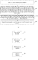
- Fig. 1 is a schematic flowchart of a method for displaying a motion path of a robot according to a first embodiment of the present disclosure, and the method may include the following steps of S101 to S104.
- the robot mainly refers to a smart cleaning robot, including a sweeping robot, a mopping robot, an automatic sweeper, a smart vacuum cleaner, etc., which is a kind of smart household appliances, and can automatically plan a cleaning path in a room by using artificial intelligence so as to complete the cleaning of the ground.
- the motion path includes a cleaning path and an auxiliary path.
- the cleaning robot firstly cleans the edge area along the edge and constructs the environment map, then plans the cleaning path according to the constructed environment map, and finally cleans the area according to the planned cleaning path.
- the robot divides the constructed environmental map into a plurality of sub-areas to be cleaned according to the position of the obstacle.
- the robot cleans the plurality of sub-areas to be cleaned in a predetermined order.
- the cleaning path includes, but is not limited to, an edge cleaning path and a planned area cleaning path.
- the auxiliary path is the path other than the cleaning path in the motion path, including but not limited to a transition path, an escape path, and a recharge path.
- the transition path refers to the motion path generated by the robot moving from the current area to another area to be cleaned.
- the escape path refers to the motion path generated by the robot in order to break free of the obstacle after being entangled by the obstacle.
- the recharge path is the path along which the robot can return from the current position to the charger.
- the motion path is recognized to determine a type of the motion path.
- the shape of the motion path may be recognized by using any existing or future possible methods.
- a display manner corresponding to the type of the motion path is determined according to the type of the motion path.
- the motion path is displayed on an electronic map in the determined display manner.
- the electronic map includes the environment map constructed by the cleaning robot during the edge cleaning process.
- a current motion path of the robot is firstly acquired, the motion path is then recognized to determine a type of the motion path, a display manner corresponding to the type of the motion path is then determined according to the type of the motion path, and finally the motion path is displayed on an electronic map in the determined display manner.
- different types of motion paths may be distinguishably displayed on the electronic map in the display manners corresponding to the types of the motion paths, which not only helps to improve the display effect of the map, but also helps the user to quickly distinguish the clean path and the auxiliary path, thereby improving the user experience and having the advantages of high ease of use and practicability.
- FIG. 2 is a schematic flowchart of a method for displaying a motion path of a robot according to a second embodiment of the present disclosure, which includes further refinement and description of step S102 in the first embodiment, and the method may include the following steps of S201 to S204.
- step S201 is the same as the step S101 in the first embodiment.
- step S101 the description of step S101 may be referred to and details are not repeatedly described herein.
- S202 it is determined whether the motion path is a pre-planned motion path and a shape of the motion path is recognized in the case that the motion path is a pre-planned motion path. And it is determined that the type of the motion path is a cleaning path in the case that the motion path is in serpentine shape and it is determined that the type of the motion path is an auxiliary path in the case that the motion path is not in serpentine shape.
- the robot in order to improve the cleaning efficiency, before the area cleaning, the robot usually pre-plans the corresponding cleaning path and the transition path according to the environment map constructed during the edge cleaning process and stores the paths locally. After comparing the current motion path with the locally stored pre-planned motion paths, the robot can determine whether the current motion path is a pre-planned motion path.
- the cleaning path is usually planned into a serpentine shape path and in order to reach another area as soon as possible to start cleaning the transition path is often planned into various shapes as needed, such as the common arc. Therefore, whether the current motion path is a cleaning path can be determined by determining whether the planned motion path is in serpentine shape, such that the type of the current motion path can be acquired.
- the display manner of the motion path is a first preset manner in the case that the type of the motion path is the clean path and it is determined that the display manner of the motion path is a second preset manner in the case that the type of the motion path is the auxiliary path.
- the first preset manner is different from the second preset manner.
- the cleaning path is displayed in red lines and the auxiliary path is displayed in white lines.
- the cleaning path is displayed in red lines and the auxiliary path is displayed in dark red lines.
- the cleaning path is displayed in solid lines and the auxiliary path is displayed in dashed lines.
- the cleaning path is displayed in thick lines and the auxiliary path is displayed in thin lines.
- the cleaning path is displayed in any manner and the auxiliary path is hidden.
- the motion path is displayed on an electronic map in the determined display manner.
- step 204 is the same as the step S104 in the first embodiment.
- the type of the motion path can be determined by recognizing the shape of the motion path after it is determined that the motion path is a pre-planned motion path, which is advantageous for accurately determining the type of the motion path so as to differently display the motion path on the electronic map, thereby having the advantages of high ease of use and practicability.
- FIG. 3 is a schematic flowchart of a method for displaying a motion path of a robot according to the third embodiment of the present disclosure, which includes further refinement and description of step S102 in the first embodiment, and the method may include the following steps of S301 to S304.
- step S301 is the same as the step S101 in the first embodiment.
- whether the motion path is a pre-planned motion path is determined, and whether the motion path conforms to an edge line of an obstacle is determined in the case that the motion path is not a pre-planned motion path. It is determined that the type of the motion path is a cleaning path in the case that the motion path conforms to the edge line of the obstacle and it is determined that the type of the motion path is an auxiliary path in the case that the motion path does not conform to the edge line of the obstacle.
- step S302 For the determination of whether the motion path is a pre-planned motion path in step S302, reference may be made to the related description of step S202 in the second embodiment and details are not repeatedly described herein.
- the motion path when the motion path is not a pre-planned motion path, it can be determined that the robot currently is performing edge cleaning, searching for a recharge path, or avoiding an obstacle, instead of performing the area cleaning. At this time, by determining whether the motion path conforms to the edge line of the obstacle, it may be further determined whether the motion path is an edge cleaning path. If the motion path is an edge cleaning path, it may be considered as a cleaning path that requires an emphasis display according to the present disclosure, if the motion path does not conform to the edge line of the obstacle, it may be considered as an auxiliary cleaning path that does not require an emphasis according to the present disclosure.
- the display manner of the motion path is a first preset manner in the case that the type of the motion path is the clean path and it is determined that the display manner of the motion path is a second preset manner in the case that the type of the motion path is the auxiliary path.
- the motion path is displayed on an electronic map in the determined display manner.
- the steps S303 and S304 are the same as the steps S203 and S204 in the second embodiment.
- the type of the motion path can be determined by determining whether the motion path conforms to an edge line of an obstacle after it is determined that the motion path is a pre-planned motion path, which is advantageous for accurately determining the type of the motion path so as to differently display the motion path on the electronic map, thereby having the advantages of high ease of use and practicability.
- Fig. 4 is a schematic diagram of a device for displaying a motion path of a robot according to a fourth embodiment of the present disclosure. For convenience of description, only parts related to this embodiment of the present disclosure are shown.
- the device for displaying a movement path of a robot may be a software unit, a hardware unit or a unit combined with software and hardware built in the robot, or may be integrated into the robot as an independent widget.
- the device for displaying a movement path of a robot includes:
- the determination module 43 specifically includes:
- the determination module 43 further includes:
- the determination module 43 further includes:
- the first preset manner includes displaying the cleaning path on the electronic map
- the second preset manner includes hiding the auxiliary path on the electronic map.
- FIG. 5 is a schematic structural diagram of a robot according to the fifth embodiment of the present disclosure.
- the robot 5 includes a processor 50, a memory 51, and a computer program 52 stored in the memory 51 and operable in the processor 50.
- the steps in the first embodiment of the method such as steps S101 to S 104 shown in FIG. 1
- the steps in the second embodiment of the method such as steps S201 to S204 shown in FIG. 2
- the steps in the third embodiment of the method such as steps S301 to S304 shown in FIG. 3
- the processor 50 executes the computer program 52
- the functions of the modules/units in each of the apparatus embodiments described above, such as the functions of the modules 41 to 44 shown in FIG. 4 are implemented.
- the computer program 52 may be divided into one or more modules/units that are stored in the memory 51 and executed by the processor 50 to complete this invention.
- the one or more modules/units may be a series of computer program instruction segments capable of performing a particular function, the instruction segments being used to describe the execution of the computer program 52 in the robot 5.
- the computer program 52 may be divided into an acquisition module, a recognition module, a determination module and a display module, and the specific functions of the respective modules are as follows.
- the acquisition module is configured to acquire a current motion path of the robot.
- the recognition module is configured to recognize the motion path to determine a type of the motion path.
- the determination module is configured to determine, according to the type of the motion path, a display manner corresponding to the type of the motion path.
- the display module is configured to display the motion path on an electronic map in the determined display manner.
- the robot may include, but is not limited to, the processor 50 and the memory 51. It will be understood by those skilled in the art that FIG. 5 is merely an example of the robot 5, does not constitute a limitation of the robot 5, may include more or less components than those illustrated, or may combine some components, or may include different components.
- the terminal device may further include an input/output device, a network access device, a bus, a display, and the like.
- the processor 50 may be CPU (Central Processing Unit), and may alternatively be other general purpose processor, DSP (Digital Signal Processor), ASIC (Application Specific Integrated Circuit), FGPA (Field-Programmable Gate Array), or some other programmable logic devices, discrete gate or transistor logic device, discrete hardware component, etc.
- the general purpose processor may be a microprocessor, or alternatively, the processor may be any conventional processor and so on.
- the memory 51 may be an internal storage unit of the robot 10, such as a hard disk or an internal memory of the robot 10.
- the memory 51 may alternatively be an external storage device of the robot 10, such as a plug-in hard disk, a SMC (Smart Media Card), a SD (Secure Digital) card, a FC (Flash Card), equipped on the robot 10. Further, the memory 51 may include both the internal storage unit and the external storage device of the robot 10.
- the memory 51 is configured to store the computer programs, and other procedures and data needed by the robot 10 for determining wellbore cross-sectional shape.
- the memory 51 may also be configured to store data that has been output or being ready to be output temporarily.
- the disclosed system, device and method could be implemented in other ways.
- the device described above are merely illustrative; for example, the division of the units is only a logical function division, and other division could be used in the actual implementation, for example, multiple units or components could be combined or integrated into another system, or some features can be ignored, or not performed.
- the coupling or direct coupling or communication connection shown or discussed could be through some interfaces, and indirect coupling or communication connection between devices or units may be electrical, mechanical, or in other manners.
- the units described as separate components could or could not be physically separate, the components shown as units could or could not be physical units, which can be located in one place, or can be distributed to multiple network elements. Parts or all of the elements could be selected according to the actual needs to achieve the object of the present embodiment.
- each of the embodiments of the present application can be integrated into a single processing unit, or exist individually and physically, or two or more than two units are integrated into a single unit.
- the aforesaid integrated unit can either be achieved by hardware, or be achieved in the form of software functional units.
- the integrated unit is achieved in the form of software functional units, and is sold or used as an independent product, it can be stored in a computer readable storage medium.
- a whole or part of flow process of implementing the method in the aforesaid embodiments of the present application can also be accomplished by using computer program to instruct relevant hardware.
- the computer program is executed by the processor, the steps in the various method embodiments described above can be implemented.
- the computer program comprises computer program codes, which can be in the form of source code, object code, executable documents or some intermediate form, etc.
- the computer readable medium can include: any entity or device that can carry the computer program codes, recording medium, USB flash disk, mobile hard disk, hard disk, optical disk, computer storage device, ROM (Read-Only Memory), RAM (Random Access Memory), electrical carrier signal, telecommunication signal and software distribution medium, etc. It needs to be explained that, the contents contained in the computer readable medium can be added or reduced appropriately according to the requirement of legislation and patent practice in a judicial district, for example, in some judicial districts, according to legislation and patent practice, the computer readable medium doesn't include electrical carrier signal and telecommunication signal.
Landscapes
- Engineering & Computer Science (AREA)
- Radar, Positioning & Navigation (AREA)
- Robotics (AREA)
- Mechanical Engineering (AREA)
- Automation & Control Theory (AREA)
- Remote Sensing (AREA)
- Physics & Mathematics (AREA)
- General Physics & Mathematics (AREA)
- Aviation & Aerospace Engineering (AREA)
- General Engineering & Computer Science (AREA)
- Artificial Intelligence (AREA)
- Software Systems (AREA)
- Mathematical Physics (AREA)
- Fuzzy Systems (AREA)
- Evolutionary Computation (AREA)
- Control Of Position, Course, Altitude, Or Attitude Of Moving Bodies (AREA)
Applications Claiming Priority (1)
| Application Number | Priority Date | Filing Date | Title |
|---|---|---|---|
| CN201811571738.8A CN109605374B (zh) | 2018-12-21 | 2018-12-21 | 一种机器人运动路径显示的方法、装置及机器人 |
Publications (1)
| Publication Number | Publication Date |
|---|---|
| EP3670107A1 true EP3670107A1 (de) | 2020-06-24 |
Family
ID=66000951
Family Applications (1)
| Application Number | Title | Priority Date | Filing Date |
|---|---|---|---|
| EP19164650.4A Withdrawn EP3670107A1 (de) | 2018-12-21 | 2019-03-22 | Verfahren und vorrichtung zum anzeigen des bewegungsweges eines roboters und roboter |
Country Status (3)
| Country | Link |
|---|---|
| US (1) | US11132002B2 (de) |
| EP (1) | EP3670107A1 (de) |
| CN (1) | CN109605374B (de) |
Families Citing this family (5)
| Publication number | Priority date | Publication date | Assignee | Title |
|---|---|---|---|---|
| CN112540600A (zh) * | 2019-09-19 | 2021-03-23 | 苏州宝时得电动工具有限公司 | 自移动设备工作区域的边界修正方法及自移动设备 |
| JP7546223B2 (ja) | 2020-02-27 | 2024-09-06 | パナソニックIpマネジメント株式会社 | 情報提示方法、情報提示装置、及び、プログラム |
| CA3224602A1 (en) * | 2021-04-01 | 2022-10-06 | Sanctuary Cognitive Systems Corporation | System for presenting robotic data flows for application development |
| CN113693501A (zh) * | 2021-06-09 | 2021-11-26 | 北京石头世纪科技股份有限公司 | 清洁设备和清洁路径、清洁地图生成方法及生成系统 |
| CN114636415A (zh) * | 2022-02-21 | 2022-06-17 | 广州科语机器人有限公司 | 运动路线优化显示方法、装置、计算机设备及存储介质 |
Citations (2)
| Publication number | Priority date | Publication date | Assignee | Title |
|---|---|---|---|---|
| EP3199083A1 (de) * | 2014-09-24 | 2017-08-02 | Samsung Electronics Co., Ltd | Reinigungsroboter und verfahren zur steuerung des reinigungsroboters |
| US20180055326A1 (en) * | 2016-08-30 | 2018-03-01 | Lg Electronics Inc. | Robot cleaner and a system including the same |
Family Cites Families (14)
| Publication number | Priority date | Publication date | Assignee | Title |
|---|---|---|---|---|
| US10521960B2 (en) * | 2017-05-03 | 2019-12-31 | General Electric Company | System and method for generating three-dimensional robotic inspection plan |
| US20050010331A1 (en) * | 2003-03-14 | 2005-01-13 | Taylor Charles E. | Robot vacuum with floor type modes |
| JP2006130005A (ja) * | 2004-11-04 | 2006-05-25 | Funai Electric Co Ltd | 薬剤散布機能付き掃除ロボット |
| KR101392123B1 (ko) * | 2005-02-18 | 2014-05-27 | 아이로보트 코퍼레이션 | 자동 청소 로봇 |
| US7912596B2 (en) * | 2007-05-30 | 2011-03-22 | Honeywell International Inc. | Vehicle trajectory visualization system |
| KR101752190B1 (ko) * | 2010-11-24 | 2017-06-30 | 삼성전자주식회사 | 로봇청소기 및 그 제어방법 |
| CN104133476B (zh) * | 2014-07-31 | 2017-01-18 | 四川阿泰因机器人智能装备有限公司 | 巡检机器人自适应路径跟踪方法 |
| KR102431996B1 (ko) * | 2015-10-12 | 2022-08-16 | 삼성전자주식회사 | 로봇 청소기 및 그 제어 방법 |
| WO2018120208A1 (zh) * | 2016-12-30 | 2018-07-05 | 深圳配天智能技术研究院有限公司 | 一种码垛路径模式的确定方法、装置及机器人 |
| US10919153B2 (en) * | 2017-03-06 | 2021-02-16 | Canon Kabushiki Kaisha | Teaching method for teaching operations to a plurality of robots and teaching system used therefor |
| CN106863305B (zh) * | 2017-03-29 | 2019-12-17 | 赵博皓 | 一种扫地机器人房间地图创建方法及装置 |
| CN108209741B (zh) * | 2017-08-30 | 2020-05-26 | 深圳乐动机器人有限公司 | 清洁机器人控制方法和清洁机器人 |
| CN108037699B (zh) * | 2017-12-12 | 2020-04-07 | 深圳市天颐健康科技有限公司 | 机器人、机器人的控制方法和计算机可读存储介质 |
| CN108673496B (zh) * | 2018-05-02 | 2021-05-11 | 苏州寻迹智行机器人技术有限公司 | 一种基于纯追踪模型的工业机器人路径跟踪方法 |
-
2018
- 2018-12-21 CN CN201811571738.8A patent/CN109605374B/zh active Active
-
2019
- 2019-02-27 US US16/287,026 patent/US11132002B2/en active Active
- 2019-03-22 EP EP19164650.4A patent/EP3670107A1/de not_active Withdrawn
Patent Citations (2)
| Publication number | Priority date | Publication date | Assignee | Title |
|---|---|---|---|---|
| EP3199083A1 (de) * | 2014-09-24 | 2017-08-02 | Samsung Electronics Co., Ltd | Reinigungsroboter und verfahren zur steuerung des reinigungsroboters |
| US20180055326A1 (en) * | 2016-08-30 | 2018-03-01 | Lg Electronics Inc. | Robot cleaner and a system including the same |
Non-Patent Citations (1)
| Title |
|---|
| LANG S Y T ET AL: "Coordination of behaviours for mobile robot floor cleaning", INTELLIGENT ROBOTS AND SYSTEMS, 1998. PROCEEDINGS., 1998 IEEE/RSJ INTE RNATIONALCONFERENCE ON, IEEE, vol. 2, 13 October 1998 (1998-10-13), pages 1236 - 1241, XP010311567, ISBN: 978-0-7803-4465-5, DOI: 10.1109/IROS.1998.727468 * |
Also Published As
| Publication number | Publication date |
|---|---|
| US11132002B2 (en) | 2021-09-28 |
| CN109605374A (zh) | 2019-04-12 |
| CN109605374B (zh) | 2023-09-29 |
| US20200201352A1 (en) | 2020-06-25 |
Similar Documents
| Publication | Publication Date | Title |
|---|---|---|
| US11132002B2 (en) | Method and device for displaying motion path of robot and robot | |
| US11822784B2 (en) | Split-screen display processing method and apparatus, device, and storage medium | |
| RU2704603C1 (ru) | Способ зарядки и зарядное устройство робота-уборщика | |
| CN106205186A (zh) | 一种推荐停车位置的方法及终端 | |
| EP3974778A1 (de) | Verfahren und vorrichtung zur aktualisierung einer arbeitskarte eines mobilen roboters und speichermedium | |
| CN105955525B (zh) | 触摸轨迹跟踪方法、装置和显示设备 | |
| CN109582015B (zh) | 一种室内清扫规划的方法、装置及机器人 | |
| CN105975160A (zh) | 一种防误触的方法及终端 | |
| CN109508002A (zh) | 一种机器人清扫地面的方法、装置及机器人 | |
| CN105487784A (zh) | 电子终端的控制方法、装置、终端和系统 | |
| CN108648140A (zh) | 图像拼接方法、系统、设备及存储介质 | |
| CN110362622A (zh) | 基于实时数仓的实时流处理系统、方法、设备及存储介质 | |
| CN106786960A (zh) | 充电控制方法、装置及终端 | |
| CN111694994A (zh) | 信息处理方法及装置 | |
| CN108903816A (zh) | 一种清扫方法、控制器及智能清扫设备 | |
| CN105183311A (zh) | 一种文件夹的合并方法及装置 | |
| EP4242769A1 (de) | Verfahren und vorrichtung zur umgehung eines objekts, medium und elektronische vorrichtung | |
| CN113720337A (zh) | 扫地机器人的地图编辑方法及装置、存储介质、电子设备 | |
| CN110297432B (zh) | 机器人动作序列生成方法、装置和系统 | |
| CN109710362A (zh) | 截图处理方法、计算设备及计算机存储介质 | |
| CN110464263A (zh) | 一种控制机器人清洁的方法及机器人 | |
| CN109509257A (zh) | 室内楼层级别构件图形形成方法、终端及存储介质 | |
| CN112927278B (zh) | 控制方法、装置、机器人及计算机可读存储介质 | |
| CN114343507A (zh) | 地图数据的生成方法、装置及扫地机器人 | |
| CN118106957A (zh) | 机器人控制方法、装置、计算机可读存储介质及机器人 |
Legal Events
| Date | Code | Title | Description |
|---|---|---|---|
| PUAI | Public reference made under article 153(3) epc to a published international application that has entered the european phase |
Free format text: ORIGINAL CODE: 0009012 |
|
| STAA | Information on the status of an ep patent application or granted ep patent |
Free format text: STATUS: THE APPLICATION HAS BEEN PUBLISHED |
|
| AK | Designated contracting states |
Kind code of ref document: A1 Designated state(s): AL AT BE BG CH CY CZ DE DK EE ES FI FR GB GR HR HU IE IS IT LI LT LU LV MC MK MT NL NO PL PT RO RS SE SI SK SM TR |
|
| AX | Request for extension of the european patent |
Extension state: BA ME |
|
| STAA | Information on the status of an ep patent application or granted ep patent |
Free format text: STATUS: REQUEST FOR EXAMINATION WAS MADE |
|
| 17P | Request for examination filed |
Effective date: 20200710 |
|
| RBV | Designated contracting states (corrected) |
Designated state(s): AL AT BE BG CH CY CZ DE DK EE ES FI FR GB GR HR HU IE IS IT LI LT LU LV MC MK MT NL NO PL PT RO RS SE SI SK SM TR |
|
| STAA | Information on the status of an ep patent application or granted ep patent |
Free format text: STATUS: EXAMINATION IS IN PROGRESS |
|
| 17Q | First examination report despatched |
Effective date: 20211011 |
|
| STAA | Information on the status of an ep patent application or granted ep patent |
Free format text: STATUS: THE APPLICATION IS DEEMED TO BE WITHDRAWN |
|
| 18D | Application deemed to be withdrawn |
Effective date: 20241001 |