EP3670114A1 - Élément de préhension permettant d'appréhender un objet - Google Patents
Élément de préhension permettant d'appréhender un objet Download PDFInfo
- Publication number
- EP3670114A1 EP3670114A1 EP19217970.3A EP19217970A EP3670114A1 EP 3670114 A1 EP3670114 A1 EP 3670114A1 EP 19217970 A EP19217970 A EP 19217970A EP 3670114 A1 EP3670114 A1 EP 3670114A1
- Authority
- EP
- European Patent Office
- Prior art keywords
- thermoplastic
- gripping
- state
- gripping element
- holder
- Prior art date
- Legal status (The legal status is an assumption and is not a legal conclusion. Google has not performed a legal analysis and makes no representation as to the accuracy of the status listed.)
- Withdrawn
Links
Images


Classifications
-
- B—PERFORMING OPERATIONS; TRANSPORTING
- B25—HAND TOOLS; PORTABLE POWER-DRIVEN TOOLS; MANIPULATORS
- B25J—MANIPULATORS; CHAMBERS PROVIDED WITH MANIPULATION DEVICES
- B25J15/00—Gripping heads and other end effectors
- B25J15/0033—Gripping heads and other end effectors with gripping surfaces having special shapes
-
- B—PERFORMING OPERATIONS; TRANSPORTING
- B25—HAND TOOLS; PORTABLE POWER-DRIVEN TOOLS; MANIPULATORS
- B25J—MANIPULATORS; CHAMBERS PROVIDED WITH MANIPULATION DEVICES
- B25J19/00—Accessories fitted to manipulators, e.g. for monitoring, for viewing; Safety devices combined with or specially adapted for use in connection with manipulators
- B25J19/0054—Cooling means
-
- B—PERFORMING OPERATIONS; TRANSPORTING
- B25—HAND TOOLS; PORTABLE POWER-DRIVEN TOOLS; MANIPULATORS
- B25J—MANIPULATORS; CHAMBERS PROVIDED WITH MANIPULATION DEVICES
- B25J9/00—Program-controlled manipulators
- B25J9/10—Program-controlled manipulators characterised by positioning means for manipulator elements
- B25J9/1085—Program-controlled manipulators characterised by positioning means for manipulator elements positioning by means of shape-memory materials
Definitions
- the invention relates to a gripping element for gripping an object.
- the invention also relates to a gripping device with such a gripping element.
- the invention also relates to a method for gripping an object.
- a large number of gripping devices are known from the prior art, by means of which objects can be gripped and transported from an actual position to a desired position. So gripping devices are known in which the gripping process is carried out by means of an adhesive. Such gripping devices are limited to the handling and positioning of small parts on the order of a few millimeters, as well as the gripping and handling of semi-finished products that are asleep, essentially textile semi-finished products.
- gripping devices are known in which a liquid film, usually water, is placed and frozen between a gripping element and the object to be gripped.
- the material to be gripped is gripped and moved into the desired position and released again by thawing the water by predominantly cohesive force transmission via the frozen water, which acts like an adhesive.
- a disadvantage of the known gripping devices is that they cannot be used flexibly.
- the gripping devices are usually developed based on the geometry of the object to be gripped and / or their use depends on the surface condition of the object to be gripped.
- the object of the invention is therefore to provide a gripping element that can be used flexibly.
- the object is achieved by a gripping element for gripping an object, with a thermoplastic material which changes from an initial state in which there is no non-positive and / or positive connection between the thermoplastic material and the object to a gripping state in which and / or there is a positive connection between the thermoplastic and the object, and can be transferred from the gripping state back to the initial state.
- Another object of the invention is to provide a method by means of which differently shaped objects can be gripped.
- the gripping element according to the invention has the advantage that the gripping element can be used flexibly. This enables the object to be gripped independently of the object geometry and / or the surface condition of the object.
- the flexible use of the gripping element is possible because of the thermoplastic Plastic is designed such that it can be transferred from the gripping state back to the starting state.
- thermoplastic is a plastic that can be deformed in a certain temperature range. This process is reversible so that it can be repeated any number of times by cooling or heating.
- the plastic changes from a solid state to a rubbery to viscous state when a glass transition temperature is exceeded and changes from the rubbery to viscous state to the solid state when the glass transition temperature is undershot.
- the gripping element can move the object from an actual position to a target position in the gripping state.
- the object can be moved in at least one, preferably three, spatial directions.
- the object can be moved and / or rotated linearly by means of the gripping element and the gripping device described in more detail below.
- the thermoplastic can be heated to transfer the thermoplastic from the initial state to the gripping state.
- the thermoplastic can then be brought into contact with the object.
- the thermoplastic material are cooled to produce a non-positive and / or positive connection between the thermoplastic and the object.
- thermoplastic material can be transferred from the initial state into the gripping state in a particularly simple manner.
- the transfer of the thermoplastic from the initial state into the gripping state in particular the establishment of the non-positive and / or positive connection between the thermoplastic and the object, can be achieved by controlling or regulating the temperature of the thermoplastic.
- thermoplastic can be heated to a temperature which is greater than a glass transition temperature of the thermoplastic before the thermoplastic is brought into contact with the object.
- thermoplastic When it is brought into the gripping state, the thermoplastic, which is in the viscous state, can be brought into contact with the object. The object is pressed against a material section of the thermoplastic. Since the thermoplastic is in a viscous form, the material section of the thermoplastic gives way, so that the object is introduced into the thermoplastic. After the object has been introduced into the thermoplastic, the thermoplastic can partially enclose the object.
- thermoplastic can consist of a solid material and therefore no recesses has, into which the object is introduced.
- the object can be introduced into the thermoplastic material such that a part of the object protrudes from the thermoplastic material.
- the contact between the thermoplastic and the object can be established by moving the gripping element and / or the object in such a way that the object is introduced into the thermoplastic, as described above.
- the insertion can be realized in a particularly simple manner by moving the object and / or the gripping element relative to one another.
- the gripping element can preferably be moved relative to the object.
- the gripping element can be moved linearly.
- the non-positive and / or positive connection can be realized in the next step in a simple manner by cooling the thermoplastic material to a temperature which is below the glass transition temperature. It depends on the object geometry whether a non-positive and / or a positive connection is realized. After the cooling process, the thermoplastic is in the gripping state.
- thermoplastic When the thermoplastic is transferred from the gripping state back to the initial state, the thermoplastic can be heated and then the contact between the thermoplastic and the object can be released. Before the contact between the thermoplastic and the object is released, the thermoplastic can be heated to a temperature which is greater than the glass transition temperature of the thermoplastic.
- thermoplastic By heating the thermoplastic in this way, the contact between the thermoplastic and the object can be released in a simple manner.
- a temperature of the thermoplastic that is above the glass transition temperature of the thermoplastic there is no longer a positive and / or non-positive connection between the thermoplastic and the object. Therefore, the thermoplastic can be detached from the object in a simple manner.
- the contact between the thermoplastic and the object can be released in a simple manner by moving the gripping element and / or the object such that the object emerges from the thermoplastic and / or does not displace any material section of the thermoplastic.
- the object no longer exerts pressure on the thermoplastic.
- the gripping element can be moved in a direction away from the object.
- the gripping element can be moved linearly.
- the object can be moved in a direction away from the thermoplastic.
- the movement of the gripping element can be directed in the opposite direction to the movement of the gripping element when the thermoplastic material is transferred from the initial state to the gripping state.
- the thermoplastic can be a thermoplastic with shape memory properties.
- a thermoplastic can be realized by an appropriate manufacturing process.
- the thermoplastic has to be manufactured under high pressure and high temperature.
- the thermoplastic is preferably introduced between two plates during production. They are in the making occurring pressures and temperatures higher than the pressures and temperatures occurring during the gripping process.
- thermoplastic Due to the shape memory property, the thermoplastic always has the same design in the initial state. This is advantageous because the thermoplastic in the initial state can be designed in such a way that it can grip a large number of objects with different geometries. In particular, the thermoplastic can easily grip another object with a different geometry after gripping an object and then transferring it to the initial state.
- the thermoplastic can have a substantially rectangular, in particular rectangular, contour in cross section.
- a thermoplastic formed in this way enables a large number of differently shaped objects to be gripped.
- the thermoplastic can be a paraffin.
- Paraffin has the advantage that the glass transition temperature is not too high, so that the amount of heat required for heating is not high.
- the gripping element can have a heating element for heating the thermoplastic.
- the heating element can be designed as a heating wire.
- the heating element can at least partially extend through the thermoplastic. The heating element enables the thermoplastic material to be heated up easily and quickly.
- the thermoplastic can have a thermally conductive filler.
- the thermoplastic can have graphite fibers.
- the filler and / or the graphite fibers have the advantage that they conduct heat well. This is advantageous in that the gripping process is time-critical in some industrial areas and therefore particularly rapid heating and cooling of the thermoplastic is required.
- the gripping element can have a thermoplastic holder for holding the thermoplastic.
- the thermoplastic can be firmly connected to the thermoplastic holder.
- the thermoplastic can be integrally connected to the thermoplastic holder. As a result, a simple gripping element can be provided.
- the gripping element can have an anti-adhesion agent to prevent adhesion between the thermoplastic material and the object.
- the anti-adhesion agent is advantageous if the gripped object has to be placed precisely by means of the gripping element.
- the anti-adhesion agent prevents the object from being placed in a desired position due to a material connection between the gripped object and the thermoplastic.
- the anti-adhesion agent can at least partially encase the thermoplastic.
- the thermoplastic can be at least partially coated with the anti-adhesive.
- a gripping device with a gripping element according to the invention is particularly advantageous.
- a method for gripping the object that uses a gripping element according to the invention or a gripping device is particularly advantageous.
- the gripping device has a holder, the gripping element being operatively connected to the holder.
- the operative connection can be designed in this way be that the gripping element follows a movement of the holder. In particular, it can thereby be ensured in a simple manner that after the non-positive and / or positive connection has been established between the thermoplastic and the object, the object can be transported to a desired position by means of the gripping device.
- thermoplastic holder can be releasably operatively connected to the holder again. This offers the advantage that, for example, in the case of a defective gripping element only the gripping element has to be removed and not the entire gripping device.
- the gripping device can have a cooling device for cooling the gripping element, in particular the thermoplastic, and / or a heating device for heating the gripping element, in particular the thermoplastic.
- a particularly compact gripping device is realized if the gripping device has a Peltier element.
- the Peltier element functions as a heating device and / or as a cooling device.
- the Peltier element can be thermally conductively connected to the gripping element.
- the Peltier element can be non-positively and / or positively connected to the gripping element.
- a heat-conducting connection between the gripping element and the Peltier element is present if the heat flow between the gripping element and the Peltier element is not interrupted by a gas area.
- the gripping device can also have a further cooling device.
- the further cooling device can have a fan.
- the gripping device can have a heat sink which is connected in a heat-conducting manner to the gripping element.
- a heat-conducting connection between the heat sink and the gripping element is present if the heat flow between the gripping element and the heat sink is not interrupted by a gas area, but rather by solid bodies.
- the heat sink can be indirectly connected to the gripping element in a heat-conducting manner. The heat flow from the gripping element via the Peltier element to the heat sink can thus take place without the heat flow being interrupted by a gas region.
- the further cooling device can be arranged such that it cools the heat sink, in particular by convection.
- the heat sink can have a large number of cooling fins for increasing the surface area and thus for improving the heat emission.
- the heat sink can be operatively connected to the holder.
- the heat sink can be arranged at least partially in a cavity of the holder. This enables a compact design of the gripping device.
- the gripping device can have a displacement device for moving the holder. As a result, the object can be easily transported from the actual position, in which the object is gripped by the gripping element, to a desired position.
- the gripping device can have an, in particular electrical, control device for controlling the heating device and / or the cooling device and / or the further cooling device and / or the heating element and / or the displacement device.
- the control device can be designed in such a way that it transfers the thermoplastic plastic from the initial state into the gripping state.
- the control device can cause the thermoplastic to heat up and then bring the thermoplastic into contact with the object.
- the control device can cause the thermoplastic to be heated to a temperature above the glass transition temperature.
- the control device can control the movement device in order to cause the gripping element to move.
- the control device can cause the thermoplastic to subsequently cool to a temperature below the glass transition temperature in order to establish the non-positive and / or positive connection between the thermoplastic and the object.
- the control device can also cause the thermoplastic to be transferred from the gripping state to the starting state.
- the control device can cause the thermoplastic to be heated to a temperature above the glass transition temperature.
- the control device can then control the displacement device in order to cause the gripping element to move in order to release the contact between the thermoplastic material and the object.
- the gripping device can have sensors, in particular temperature sensors, which are electrically connected to the control device.
- the heating or cooling process of the thermoplastic can thus be regulated in a simple manner.
- the control device enables the gripping process to be carried out automatically.
- the method for gripping the object can be carried out automatically.
- Automatically means that the gripping process can be carried out without user intervention.
- the object to be gripped can have a weight of 5 grams to 50 kilograms.
- the object to be gripped can be a workpiece, in particular an arbitrarily designed workpiece.
- the gripping device can be used in production plants and / or industrial plants.
- the gripping device can be used in a handling device and / or automation device.
- the handling device and / or the automation device can have the gripping device.
- a robot and / or a portal system, in particular a three-axis portal system, can preferably have the gripping device.
- FIG 1 shows a gripping element 1 according to the invention and an object 2 to be gripped.
- the gripping element 1 has a thermoplastic plastic 3 and a thermoplastic holder 5.
- the thermoplastic holder 5 holds the thermoplastic plastic 3.
- the thermoplastic plastic 3 is firmly connected to the thermoplastic holder 5.
- Figure 1 shows an initial state of the gripping element 1. In the initial state there is no non-positive and / or positive connection between the thermoplastic 3 and the object 2. This is from Figure 1 can be seen that the gripping element 1 and the object 2 are spaced apart.
- thermoplastic 3 So that the thermoplastic 3 can be converted from the initial state into a gripping state, the thermoplastic 3 must be heated.
- the heat supply in the thermoplastic 3 is in Figure 1 symbolized by the arrow labeled Q.
- the thermoplastic 3 is heated to a temperature which is above a glass transition temperature of the thermoplastic 3. At such a temperature, the thermoplastic 3 is viscous.
- Figure 2 shows the gripping element 1 in a state in which there is contact between the thermoplastic 3 and the object 2. To establish the contact between the thermoplastic 3 and the object 2, the gripping element 1 is in the direction of displacement lowered.
- thermoplastic 3 Since the thermoplastic 3 is in viscous form after the heating process, a material section of the thermoplastic 3 can be displaced by the object 2 when the gripping element 1 is lowered. In particular, the thermoplastic 3 can widen to the side due to the displaced material section, but this is not shown in the figures. After the lowering process, part of the object 2 is completely enclosed by the thermoplastic 3. In other words, the thermoplastic 3 is in direct contact with part of the object 2 Figure 2 shown state, however, there is no non-positive connection between the thermoplastic 3 and the object 2.
- Figure 3 shows the gripping element 1 in the gripping state. In the gripping state, there is a non-positive connection between the thermoplastic 3 and the object 2.
- thermoplastic 3 based on the in Figure 2 shown state is transferred to a gripping state
- the thermoplastic 3 must be cooled.
- the thermoplastic 3 must be cooled to a temperature which is below the glass transition temperature.
- a positive connection between the thermoplastic 3 and the object 2 is produced by cooling the thermoplastic 3.
- the heat dissipation is in Figure 3 symbolized by the arrow labeled Q. After the non-positive connection between the object 2 and the thermoplastic 3 has been established, the object can be transported into the desired position.
- thermoplastic 3 back in Figure 1 initial state shown are transferred.
- the thermoplastic 3 is heated.
- thermoplastic 3 is heated to a temperature which is above the glass transition temperature of the thermoplastic 3.
- thermoplastic 3 By heating the thermoplastic 3 to a temperature above the glass transition temperature, the non-positive connection between the thermoplastic 3 and the object 2 is released. In other words, it becomes the in Figure 2 shown state realized.
- the gripping element 1 is then moved in a direction away from the object 2. In particular, the gripping element 1 is opposite to that in FIG Figure 2 shown direction of movement R moves. Following the, in particular linear, movement of the gripping element 1, the gripping element 1 is located in the in Figure 1 shown initial state.
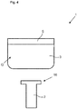
- Figure 4 shows that in Figure 1 shown gripping element 1 in an initial state and an object 2 according to a second embodiment.
- Figure 5 shows that in Figure 4 shown gripping element in a state in which there is contact between the object 2 and the thermoplastic 2.
- Figure 6 shows that in Figure 4 shown gripping element in a gripping state.
- thermoplastic 3 is transferred from the in Figure 4 initial state shown in the in Figure 6 shown gripping state analogous to that in the Figures 1 to 3 shown execution.
- thermoplastic 3 is transferred from the in Figure 6 Gripping state in the in the Figure 4 shown initial state analogous to that in the Figures 1 to 3 shown execution.
- the in the Figures 4 to 6 execution shown differs from that in Figure 1 to 3 shown embodiment in the formation of the object 2.
- the object 2 has a T-shaped end section 16.
- the gripping element 1 When the gripping element 1 is lowered in the displacement direction R, the T-shaped end section 16 presses against the thermoplastic 3 and causes a material section of the thermoplastic 3 to be displaced.
- FIG 7 shows part of the gripping device 10.
- the gripping device 10 has the gripping element 1, which is operatively connected to a holder 6 of the gripping device 10.
- the operative connection is designed such that the gripping element 1 follows a movement of the holder 6.
- the gripping element 1 is releasably operatively connected to the holder 6 again, so that it can be replaced by another gripping element 1, not shown in the figures.
- the gripping element 1 also has a heating element 4 in the form of a heating wire which extends partially through the thermoplastic 3.
- the heating wire is electrically connected to a control device 13 of the gripping device 10 by means of an electrical line 14.
- the gripping element 1, in particular the thermoplastic holder 5, is connected to a Peltier element 7 of the gripping device 10, in particular in a form-fitting manner.
- the Peltier element 7 is arranged such that heat conduction between the Peltier element 7 and the gripping element 1 he follows.
- the Peltier element 7 is also electrically connected to the control device 13 by means of an electrical line 14.
- the gripping device 10 also has a heat sink 9 and a further cooling device 8.
- the further cooling device 8 is designed as a fan and serves to cool the heat sink 9.
- the heat sink 9 is arranged in a cavity 17 of the holder 6 and is operatively connected to the holder 6.
- the heat sink 9 is thermally conductively connected to the gripping element 1.
- the heat sink 9 is indirectly connected to the gripping element 1 in a heat-conducting manner by means of the Peltier element 7.
- the cooling body 9 has a multiplicity of cooling fins 18 which face the further cooling device 8 and are cooled by the further cooling device 8.
- the further cooling device 8 can also be electrically connected to the control device 13 by means of an electrical line 14.
- the gripping device 10 also has a displacement device 15, which in Figure 7 is only partially shown.
- the holder 6 and thus the gripping element 1 can be lowered by means of the displacement device 15, so that the thermoplastic 3 can come into contact with the object 2.
- the object 2 in a gripping state of the thermoplastic material 3, can be moved from the position shown in FIG Figure 7 shown actual position can be moved into a target position, not shown in the figures.
- the moving device 15 can be connected to the control device 13 by means of an electrical line 14.
- the control device 13 can transmit control commands to the aforementioned components via the electrical lines 14.
- the heating or cooling process of the thermoplastic 3 can be controlled or controlled by means of the control device 13 be managed.
- the movement of the holder 6 and thus of the gripping element 1 can also be controlled or regulated by means of the control device 13.
Landscapes
- Engineering & Computer Science (AREA)
- Robotics (AREA)
- Mechanical Engineering (AREA)
- Lining Or Joining Of Plastics Or The Like (AREA)
Applications Claiming Priority (1)
| Application Number | Priority Date | Filing Date | Title |
|---|---|---|---|
| LU101069A LU101069B1 (de) | 2018-12-21 | 2018-12-21 | Greifelement zum Greifen eines Objekts |
Publications (1)
| Publication Number | Publication Date |
|---|---|
| EP3670114A1 true EP3670114A1 (fr) | 2020-06-24 |
Family
ID=65802138
Family Applications (1)
| Application Number | Title | Priority Date | Filing Date |
|---|---|---|---|
| EP19217970.3A Withdrawn EP3670114A1 (fr) | 2018-12-21 | 2019-12-19 | Élément de préhension permettant d'appréhender un objet |
Country Status (2)
| Country | Link |
|---|---|
| EP (1) | EP3670114A1 (fr) |
| LU (1) | LU101069B1 (fr) |
Citations (4)
| Publication number | Priority date | Publication date | Assignee | Title |
|---|---|---|---|---|
| WO1988001924A1 (fr) * | 1986-09-12 | 1988-03-24 | Raychem Corporation | Manipulateur |
| WO1998024594A2 (fr) * | 1996-12-06 | 1998-06-11 | Andromis S.A. | Dispositif de prehension en materiau a memoire de forme et procede de realisation |
| US20110089708A1 (en) * | 2009-10-17 | 2011-04-21 | Gm Global Technology Operations, Inc. | Mechanical grippers utilizing active material activation |
| US20140306473A1 (en) * | 2013-04-16 | 2014-10-16 | Raytheon Company | Robotic grabber and method of use |
-
2018
- 2018-12-21 LU LU101069A patent/LU101069B1/de active IP Right Grant
-
2019
- 2019-12-19 EP EP19217970.3A patent/EP3670114A1/fr not_active Withdrawn
Patent Citations (4)
| Publication number | Priority date | Publication date | Assignee | Title |
|---|---|---|---|---|
| WO1988001924A1 (fr) * | 1986-09-12 | 1988-03-24 | Raychem Corporation | Manipulateur |
| WO1998024594A2 (fr) * | 1996-12-06 | 1998-06-11 | Andromis S.A. | Dispositif de prehension en materiau a memoire de forme et procede de realisation |
| US20110089708A1 (en) * | 2009-10-17 | 2011-04-21 | Gm Global Technology Operations, Inc. | Mechanical grippers utilizing active material activation |
| US20140306473A1 (en) * | 2013-04-16 | 2014-10-16 | Raytheon Company | Robotic grabber and method of use |
Also Published As
| Publication number | Publication date |
|---|---|
| LU101069B1 (de) | 2020-06-24 |
Similar Documents
| Publication | Publication Date | Title |
|---|---|---|
| DE69121049T2 (de) | Verzögerndes Wärmeübertragungssystem und Verfahren zu seiner Herstellung | |
| DE102017010550A1 (de) | Vorrichtung zum thermischen Verschweißen von Kunststoffteilen sowie Anordnung enthaltend eine solche Vorrichtung | |
| DE102016101945B4 (de) | Heißnietstempel und Heißnietvorrichtung | |
| DE102016201541B4 (de) | Robotischer Greifer sowie Verfahren zum Betreiben eines solchen | |
| DE4142406C2 (de) | Verfahren zur Herstellung von Wärmeübertragungsvorrichtungen, und Werkzeuge zur Durchführung des Verfahrens | |
| DE2106725A1 (de) | Verfahren und Vorrichtung zum Herstellen von Behaltern aus thermoplastischen Kunst stoffolien | |
| CH678412A5 (fr) | ||
| DE102016117798A1 (de) | Verfahren zur Herstellung eines vorgeformten Verbundhalbzeugs sowie Verfahren zur Herstellung eines Faserverbundbauteils | |
| EP3292988B1 (fr) | Support porteur de plateforme interchangeable avec un contrôle de temperature amélioré | |
| DE102013019146A1 (de) | Verfahren zur Herstellung eines aus mehreren Lagen bestehenden Fasergeleges, sowie Greifvorrichtung zur Durchführung des Verfahrens | |
| WO2012167934A2 (fr) | Dispositif et procédé de chauffage d'un fluide | |
| LU101069B1 (de) | Greifelement zum Greifen eines Objekts | |
| DE102011120725A1 (de) | Vorrichtung und Verfahren zum Warmumformen und partiellen Härten eines Bauteils | |
| DE102019100760A1 (de) | Verfahren zum Aufheizen von Halbzeugen | |
| DE102013105401B4 (de) | Bearbeitungswerkzeug zum thermischen Bearbeiten von Bauteilen | |
| WO2016091427A1 (fr) | Élément de compensation par transfert de chaleur et véhicule à propulsion électrique pourvu d'un tel élément de compensation | |
| DE102008004858A1 (de) | Temperieren der Düsenplatte eines Unterwassergranulators | |
| EP2755808B1 (fr) | Système de poinçon bloc chauffable | |
| EP4098419A1 (fr) | Système d'outil chauffé par induction destiné au durcissement des composants en fibre plastique | |
| DE102023124266A1 (de) | Presseneinrichtung mit temperierbarem formgebendem Werkzeugteil | |
| DE102019114710A1 (de) | Vorrichtung und Verfahren | |
| WO2008135345A1 (fr) | Tête de soudage de réparation pour composant monté en surface et procédé pour faire fonctionner cette tête de soudage | |
| WO2019175190A1 (fr) | Procédé et dispositif pour riveter des pièces | |
| DE2848863C2 (de) | Vorrichtung zur vorübergehenden Kühlung oder Aufheizung von Bauelement-Gehäusen | |
| EP4245731A1 (fr) | Système de moulage de verre et procédé de fabrication de deux ou plusieurs produits en verre à partir d'une ébauche de verre |
Legal Events
| Date | Code | Title | Description |
|---|---|---|---|
| PUAI | Public reference made under article 153(3) epc to a published international application that has entered the european phase |
Free format text: ORIGINAL CODE: 0009012 |
|
| STAA | Information on the status of an ep patent application or granted ep patent |
Free format text: STATUS: THE APPLICATION HAS BEEN PUBLISHED |
|
| AK | Designated contracting states |
Kind code of ref document: A1 Designated state(s): AL AT BE BG CH CY CZ DE DK EE ES FI FR GB GR HR HU IE IS IT LI LT LU LV MC MK MT NL NO PL PT RO RS SE SI SK SM TR |
|
| AX | Request for extension of the european patent |
Extension state: BA ME |
|
| STAA | Information on the status of an ep patent application or granted ep patent |
Free format text: STATUS: THE APPLICATION IS DEEMED TO BE WITHDRAWN |
|
| 18D | Application deemed to be withdrawn |
Effective date: 20210112 |