EP3670121B1 - Machine de coupe pour produit à couper en forme de barre - Google Patents
Machine de coupe pour produit à couper en forme de barre Download PDFInfo
- Publication number
- EP3670121B1 EP3670121B1 EP19212889.0A EP19212889A EP3670121B1 EP 3670121 B1 EP3670121 B1 EP 3670121B1 EP 19212889 A EP19212889 A EP 19212889A EP 3670121 B1 EP3670121 B1 EP 3670121B1
- Authority
- EP
- European Patent Office
- Prior art keywords
- guide tube
- blade
- cutting
- face
- cutting machine
- Prior art date
- Legal status (The legal status is an assumption and is not a legal conclusion. Google has not performed a legal analysis and makes no representation as to the accuracy of the status listed.)
- Active
Links
Images


Classifications
-
- B—PERFORMING OPERATIONS; TRANSPORTING
- B26—HAND CUTTING TOOLS; CUTTING; SEVERING
- B26D—CUTTING; DETAILS COMMON TO MACHINES FOR PERFORATING, PUNCHING, CUTTING-OUT, STAMPING-OUT OR SEVERING
- B26D7/00—Details of apparatus for cutting, cutting-out, stamping-out, punching, perforating, or severing by means other than cutting
- B26D7/26—Means for mounting or adjusting the cutting member; Means for adjusting the stroke of the cutting member
- B26D7/2628—Means for adjusting the position of the cutting member
-
- B—PERFORMING OPERATIONS; TRANSPORTING
- B26—HAND CUTTING TOOLS; CUTTING; SEVERING
- B26D—CUTTING; DETAILS COMMON TO MACHINES FOR PERFORATING, PUNCHING, CUTTING-OUT, STAMPING-OUT OR SEVERING
- B26D7/00—Details of apparatus for cutting, cutting-out, stamping-out, punching, perforating, or severing by means other than cutting
- B26D7/06—Arrangements for feeding or delivering work of other than sheet, web, or filamentary form
- B26D7/0641—Arrangements for feeding or delivering work of other than sheet, web, or filamentary form using chutes, hoppers, magazines
-
- B—PERFORMING OPERATIONS; TRANSPORTING
- B26—HAND CUTTING TOOLS; CUTTING; SEVERING
- B26D—CUTTING; DETAILS COMMON TO MACHINES FOR PERFORATING, PUNCHING, CUTTING-OUT, STAMPING-OUT OR SEVERING
- B26D1/00—Cutting through work characterised by the nature or movement of the cutting member or particular materials not otherwise provided for; Apparatus or machines therefor; Cutting members therefor
- B26D1/0006—Cutting members therefor
-
- B—PERFORMING OPERATIONS; TRANSPORTING
- B26—HAND CUTTING TOOLS; CUTTING; SEVERING
- B26D—CUTTING; DETAILS COMMON TO MACHINES FOR PERFORATING, PUNCHING, CUTTING-OUT, STAMPING-OUT OR SEVERING
- B26D7/00—Details of apparatus for cutting, cutting-out, stamping-out, punching, perforating, or severing by means other than cutting
- B26D7/01—Means for holding or positioning work
-
- B—PERFORMING OPERATIONS; TRANSPORTING
- B26—HAND CUTTING TOOLS; CUTTING; SEVERING
- B26D—CUTTING; DETAILS COMMON TO MACHINES FOR PERFORATING, PUNCHING, CUTTING-OUT, STAMPING-OUT OR SEVERING
- B26D1/00—Cutting through work characterised by the nature or movement of the cutting member or particular materials not otherwise provided for; Apparatus or machines therefor; Cutting members therefor
- B26D1/01—Cutting through work characterised by the nature or movement of the cutting member or particular materials not otherwise provided for; Apparatus or machines therefor; Cutting members therefor involving a cutting member which does not travel with the work
- B26D1/12—Cutting through work characterised by the nature or movement of the cutting member or particular materials not otherwise provided for; Apparatus or machines therefor; Cutting members therefor involving a cutting member which does not travel with the work having a cutting member moving about an axis
- B26D1/14—Cutting through work characterised by the nature or movement of the cutting member or particular materials not otherwise provided for; Apparatus or machines therefor; Cutting members therefor involving a cutting member which does not travel with the work having a cutting member moving about an axis with a circular cutting member, e.g. disc cutter
- B26D1/143—Cutting through work characterised by the nature or movement of the cutting member or particular materials not otherwise provided for; Apparatus or machines therefor; Cutting members therefor involving a cutting member which does not travel with the work having a cutting member moving about an axis with a circular cutting member, e.g. disc cutter rotating about a stationary axis
- B26D1/147—Cutting through work characterised by the nature or movement of the cutting member or particular materials not otherwise provided for; Apparatus or machines therefor; Cutting members therefor involving a cutting member which does not travel with the work having a cutting member moving about an axis with a circular cutting member, e.g. disc cutter rotating about a stationary axis with horizontal cutting member
-
- B—PERFORMING OPERATIONS; TRANSPORTING
- B26—HAND CUTTING TOOLS; CUTTING; SEVERING
- B26D—CUTTING; DETAILS COMMON TO MACHINES FOR PERFORATING, PUNCHING, CUTTING-OUT, STAMPING-OUT OR SEVERING
- B26D1/00—Cutting through work characterised by the nature or movement of the cutting member or particular materials not otherwise provided for; Apparatus or machines therefor; Cutting members therefor
- B26D1/0006—Cutting members therefor
- B26D2001/002—Materials or surface treatments therefor, e.g. composite materials
-
- B—PERFORMING OPERATIONS; TRANSPORTING
- B26—HAND CUTTING TOOLS; CUTTING; SEVERING
- B26D—CUTTING; DETAILS COMMON TO MACHINES FOR PERFORATING, PUNCHING, CUTTING-OUT, STAMPING-OUT OR SEVERING
- B26D7/00—Details of apparatus for cutting, cutting-out, stamping-out, punching, perforating, or severing by means other than cutting
- B26D7/01—Means for holding or positioning work
- B26D2007/013—Means for holding or positioning work the work being tubes, rods or logs
-
- B—PERFORMING OPERATIONS; TRANSPORTING
- B26—HAND CUTTING TOOLS; CUTTING; SEVERING
- B26D—CUTTING; DETAILS COMMON TO MACHINES FOR PERFORATING, PUNCHING, CUTTING-OUT, STAMPING-OUT OR SEVERING
- B26D2210/00—Machines or methods used for cutting special materials
- B26D2210/02—Machines or methods used for cutting special materials for cutting food products, e.g. food slicers
Definitions
- the invention relates to cutting machines in which slices are to be cut from a strand-shaped or loaf-shaped material to be cut.
- the material to be cut is often guided in a guide tube, with the portion of the material to be cut protruding from the front of the guide tube on the cutting side being cut off as a disc by a rotating knife, for example, directly on the cutting-side end face of the guide tube.
- this guide tube can only consist of an axially very short so-called cutting goggle, which partially or completely surrounds that end of the material to be cut from which the slices are to be separated and the knife moves along its end face. In the following, however, only one guide tube is used throughout.
- the present application also includes solutions in which a single knife of two or more loaves guided in adjacent guide tubes simultaneously separates one slice, and / or solutions in which the guide tube is part of one around its central axis rotatable guide tube turret, around which a plurality of guide tubes are arranged.
- the knife should always cut through the material to be cut at the same, precisely defined axial distance, in particular the distance zero, to the end face of the guide tube, because this is the only way to produce slices with a defined thickness and thus also with a defined weight.
- the rotating knife for example, is supported on the side of the guide tube by the guide tube itself, on the opposite side a support that requires axial installation space - be it due to the correspondingly large thickness of the knife itself or an additional support device there - is necessary, but disadvantageous because this makes it more difficult for the knife to penetrate the material to be cut.
- an optimally thin knife would be the best solution, as it penetrates the material to be cut the easiest, but such a knife often does not have sufficient dimensional stability and, above all, insufficient positional stability, namely close to the end face of the guide tube.
- the uneven cross-section of the meat loaf is expanded to the uniform cross-section of the guide tube, so that the material to be cut has a uniform cross-section in the form of a strand or caliber, but this also causes the material to be cut under a There is increased pressure and that outside the guide tube there should be a longitudinal stop for the end of the material to be sliced that is pushed out of the guide tube.
- the knife Since the knife is not guided in a cutting gap on both sides, but only slides on one side along the end face of the guide tube, without additional measures there is a great risk that the knife will not be tight, in particular contacting, due to deformation, the irregular resistance of the material to be cut or other effects the end face of the guide tube slides along, but at a small distance therefrom, which undesirably changes the thickness and thus the weight of the disc produced.
- edge of the pane is usually frayed, which is undesirable for optical reasons.
- a grown piece of meat is surrounded by a so-called silver skin, a tendon-like material that is difficult to cut.
- a clean cutting instead of tearing through this silver skin is only possible if the cutting edge of the knife rests against the end face of the guide turret or form turret, especially when the knife emerges from the material to be cut, i.e. the guide tube cross-section.
- the knife In a cutting machine of the generic type , in which the knife is held on the end face of the guide tube by means of holding magnets, it is irrelevant whether the knife is a bar-shaped knife, a rotating circular disk-shaped knife or a rotating sickle-shaped knife or the knife of a band saw.
- the holding magnet (s) are arranged in the penetration direction only near the exit side of the guide tube cross section and outside the guide tube cross section, and not near the entry side.
- the direction of penetration is understood to mean the perpendicular to the knife edge which lies in the knife plane defined by the knife edge and / or the main plane of the knife. If the knife edge is curved, the perpendicular starts at the middle of the length of the knife edge.
- the knife is only subjected to magnetic force in the last part of the passage section of its knife edge through the material to be cut, i.e. through the guide tube cross-section, in the direction of the end face of the guide tube and thereby usually also brought into contact with the end face.
- this offers the advantage that before the magnetic force acts on the knife, i.e. in the first part of the passage of the cutting edge along the penetration path, there is no application of magnetic force to the knife in the direction of the end face of the guide tube and the knife does not or only the end face contacted with a very low contact force, so that there is hardly any heating of the knife and guide tube and hardly any increase in the cutting force to be applied.
- the holding magnet or magnets are only arranged in the last third of the penetration path of the knife edge in the penetration direction.
- the at least one holding magnet is arranged as close as possible to the outer circumference of the guide tube cross-section in order to apply magnetic force to the knife in the area of the guide tube cross-section in the direction of the end face.
- the holding magnet is preferably arranged transversely to the penetration direction, i.e. in the radial direction of the guide tube cross section, closer than 30 mm, better closer than 20 mm, better closer than 10 mm to the circumference of the guide tube cross section.
- the one or more holding magnets are arranged so close to the longitudinal position of the front, cutting-side face that the tensile force of the holding magnet on the knife at the longitudinal position of the cutting-side face still reaches or exceeds a predetermined minimum tensile force.
- the longitudinal position of the holding magnet is preferably adjustable for this purpose.
- the minimum tensile force of the individual magnets mounted in the machine at the longitudinal position of the cutting-side face should be at least between 100 N and 10 N, better between 70 N and 20 N, better between 50 N and 30 N, especially in relation to the knife used -Material.
- the sum of the minimum tensile forces of all holding magnets present on a guide tube should be between 400 N and 40 N, better between 280 N and 160 N, better between 200 N and 120 N, especially compared to the knife material used. All holding magnets present on a guide tube should in particular be those holding magnets which, when a pane protruding from this guide gate is cut off, at most all of them act together on the cutting knife.
- So-called knife steel is preferably used as the material for the knife, which is usually defined in such a way that its grade number starts with 1.40 - 1.46, preferably 1.40.
- the nickel content should be a maximum of 2.5% by weight and the carbon content a maximum of 1.2% by weight, while the chromium content should be at least 10.5% by weight, better still 13-15% by weight. If molybdenum is contained, its proportion should not be higher than 1.0% by weight.
- the counter number following in the type number is preferably between 16 and 34 and is preferably 21.
- the subsequent last two digits of the type number for the steel production process and the treatment state are preferably 3 for the steel production process and / or 4 for the treatment state.
- a steel of the grade number 1.4021.34 is therefore preferably used as the knife steel.
- the steel used for the knife must of course be able to be acted upon by magnetic force, i.e. it must be a soft magnetic material.
- the knife is preferably positioned with respect to the end face of the guide tube in the axial direction in such a way that the one facing the guide tube On the side of the knife without application of magnetic force, a narrow cutting gap of no more than 0.5 mm, better no more than 0.3 mm, better no more than 0.2 mm to the guide tube.
- the knife In order to pull the knife by means of the magnetic force of the at least one holding magnet until it makes contact with the end face - if the knife does not contact the end face without being applied by magnetic force - the knife should have a thickness of at most 10 mm, in particular at most 8 mm, in particular at most 6 mm, in particular have a maximum of 4 mm, in particular a maximum of 3 mm.
- the knife should have an extension of at least 10 mm, in particular at least 30 mm, in particular at least 50 mm, in the penetration direction.
- the extent from the cutting edge to the bearing block in which the knife is mounted is to be measured.
- the knife consists of a soft magnetic material, that is, a material on which a force can be exerted by means of a magnet.
- the knife is preferably made of stainless steel, that is to say a mostly high-alloy steel which does not rust under the conditions of use of such a cutting machine, but which at the same time has soft magnetic properties.
- the knife is preferably a knife that is only sharpened on one side, the sharpened side preferably being on the side of the knife facing away from the guide tube. Therefore, regardless of the exact dimensions of the knife, that is, its regrinding state, no changes to the positioning of the magnets, in particular in the axial direction, have to be made.
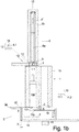
- the base frame of the cutting machine is stored.
- the guide tube openings 1.1-1.5 are used to receive a loaf 100 to be cut into slices, which in the initial state has a has an elongated but irregular shape, so that, corresponding to the cross-section of the loaf 100 in the initial state, it can optionally be introduced into a guide tube opening 1.1-1.5 with the best cross-section from above, from the loading end 1b, which of course does not apply to this the cutting position 12 may be, since there the longitudinal press drive 6 prevents the insertion from above.
- That angular position or angular segment with respect to the axis of rotation 1 'of the guide tube turret 1 which is swept over by the knife in use is referred to as the cutting position 12.
- the cutting position 12 is the angular position at which the penetration direction 2 is located.
- a rotating, circular disk-shaped knife 3 is arranged, which is driven to rotate around a knife axis 3 ', which is preferably parallel to the switching axis 1', the axis of rotation of the Guide tube turret 1 is located.
- the rotating knife 3 can be moved back and forth in a 1st transverse direction 11.1 to the longitudinal direction 10, which corresponds to the direction of the indexing axis 1 'of the guide tube turret 1, radially to the guide tube opening in the cutting position 12, e.g. 1.1 to cut off slices 101 of the product to be cut 100.
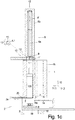
- the severed disc 101 falls onto the discharge conveyor 8 arranged below and is moved by this, for example, in the direction of view of the Figure 1c transported away.
- FIG Figure 2c thus shows the state immediately before the severed disc 101 fell onto the discharge conveyor 8, while in FIG Figure 1c the disk 101 is already on the discharge conveyor 8.
- the knife axis 3 ′ can also perform an arcuate, oscillating, or circular movement in order to cut off one disc 101 at a time.
- a longitudinal pressing drive 6 is arranged above the guide tube turret 1 at the so-called cutting position 12, viewed in the direction of the indexing axis 1 'and lying within the circumference of the guide tube turret 1, on the base frame of the machine.
- the longitudinal press drive 6 consists of a working cylinder, preferably a hydraulic cylinder, the piston rod of which can be moved in the longitudinal direction 10 6a when the working medium is applied from the lower, open end of the cylinder 6b increasingly extends and with its front end a longitudinal ram 4.1, which fits into the cross-section 1.1 'of the guide tube opening 1.1 below, pushes it into it until it rests on the loaf 100 and this presses down in the longitudinal direction 10 against a stop.
- a working cylinder preferably a hydraulic cylinder
- the stop serves as a stop Figure 1d Stop plate 14 that is moved up to the lower end face of the guide tube opening 1.1 located in the cutting position 12 and held, preferably completely covering this guide tube opening 1.1 before the start of the cutting process.
- longitudinal press rams 4.1 - 4.5 are arranged in a circular manner around its axis of rotation 13 ', the cross sections of which correspond to one of the cross sections 1.1' - 1.5 'of the guide tube openings 1.1 - 1.5 and are thus arranged in the press ram turret 13 are that they fit exactly and preferably liquid-tight into one of the guide tube openings 1.1-1.5 when they are in the cutting position 12 above this matching guide tube opening.
- the ram turret 13 can be rotated about the likewise upright, parallel to the indexing axis 1 ', but offset in a transverse direction, the indexing axis 13' so that with a certain guide tube opening 1.1 at the cutting position the same cross section 4.1 ' having longitudinal ram 4.1 can be positioned over this guide tube opening 1.1 by rotating the press ram turret 13 accordingly.
- the coupling parts 9a located on the upper side of the longitudinal ram 4.1-4.5 lie on a circular path around the switching axis 13 'of the press ram turret 13. If the corresponding longitudinal ram 4.1 is in alignment and above the cutting position 12, exactly in the path of movement of the another, complementary coupling part 9b arranged at the front end of the piston rod 6a.
- the longitudinal press ram 4.1 moves against a ram stop 15 when it reaches the corresponding recess in the press ram turret 13 or in this recess, so that when the piston rod 6a is retracted further, the coupling 9 solves and automatically releases the corresponding longitudinal ram 4.1, which is now held again in the ram turret 13 in the recess provided for the longitudinal ram 4.1, for example magnetically or by suitable locking elements there.
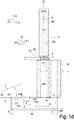
- Switching axis 1 means that the guide tube turret 1 can be rotated, but can also be locked in certain angular positions so that it is possible to switch from one to the next of the defined angular positions.
- the 1st transverse direction 11.1 is always spoken of, without restricting the invention to this, although the direction of displacement 2 is also a different transverse to the longitudinal direction 10 of the guide tube turret 1 can be direction.
- the knife 3 is mounted rotatably about its knife axis 3 ′ on a slide 19, which can be moved in this direction of displacement 2 with respect to the cutting base frame 18.
- the stop plate 14 is also carried by the slide 19, but is adjustable with respect to it at least in the axial direction 10, possibly also in the radial direction.
- knife 3 and stop plate 14 move preferably synchronously in penetration direction 2, preferably 1st transverse direction 11.1, so that the resulting disc 101 is increasingly pushed through the gap between cutting edge 3a of knife 3 and the functional edge 14a of stop plate 14 facing the knife .
- the functional edge 14a is - in the axial direction 10, for example viewed from below - preferably concavely curved and runs in alignment or slightly radially outward in this viewing direction, in particular at a constant distance over the length of the functional edge, compared to the circular circumference of the cutting edge 3a .
- the stop plate 14 and thus its functional edge 14a can additionally according to FIG Figure 1a can be adjusted in the 1st transverse direction 11.1 with respect to the carriage 19 and thus the cutting edge 3a of the knife 3, preferably also during the cutting process.
- Figure 1d shows a state of the cutting machine in which two processes are shown at the same time, but in practice they do not have to occur simultaneously: On the one hand, the stop plate 14 is raised so far that it rests directly on the lower end face of the guide tube turret 1, the cutting end 1a, as may be necessary as a stop for the longitudinal pressing of the loaf 100 at the cutting position 12.
- the knife 3 is shifted so far away from the indexing axis 1 'of the guide tube turret 1 that, viewed in the longitudinal direction 10, it is completely outside the cross section of the guide tube turret 1, so that the knife 3, which is on its underside from the slide 19 is supported, is freely accessible from the top over its entire surface and can be removed upwards after loosening a quick-release fastener 20 and exchanged for another knife.
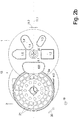
- the ones in the Figures 2a to 2c The ones in the Figures 2a to 2c
- the depressions 21 shown around the center of the knife 3, preferably on a circular path, as well as openings 22 through the disc-shaped knife 3 serve primarily to reduce the weight of the knife 3 and the openings 22 also serve as gripping openings for gripping the knife 3 when changing knives.
- holding magnets 7 are present, but in the penetration direction 2 only near the end of the penetration path 2 ':
- FIG. 2a using the example of the guide tube opening 1.2 shows - viewed in the longitudinal direction 10 - on the two sides of each shaped tube opening with respect to its penetration direction 2, here the radial direction with respect to the switching axis 1 'of the guide tube turret 1 through the center of the respective guide tube Opening, at least one holding magnet 7, usually at least two holding magnets 7 each, but only in the last third of the penetration distance 2 ', because the knife 3 should only be used there, so that the knife edge 3a rests against the end face 1a of the guide tube turret 1 with pretension at the exit end 2a of the penetration path 2 ′, which is located radially on the inside with respect to the guide tube turret 1.
- Figure 4 shows - again viewed in the longitudinal direction 10, usually the longitudinal pressing direction - the arrangement of the holding magnets 7 with two guide tube openings 1.1, 1.2 running parallel next to one another, which additionally in a 1st transverse direction to the longitudinal direction 10 by means of a transverse pressing of the loaf inserted therein of a cross press ram. Since in this case the penetration direction 2 often coincides with the transverse compression direction, the length of the penetration path 2 ', which the knife edge 3a has to cover through the cross section of the guide tube opening, also changes with the extent of the transverse compression.
- two elongated blind holes 24 extending in the penetration direction 2 are provided on both sides of each of the two guide tube openings, with a single such elongated blind hole 24 between them being sufficient if the distance between the two guide tube openings 1.1, 1.2 is sufficiently small.
- the holding magnets 7 can be inserted into these blind holes 24 along these blind holes 24 - preferably by means of magnet holders 25 to be explained - at different longitudinal positions, namely always in the penetration direction 2 in the last or the last two insertion positions along the penetration path 2 ' whose exit side 2a.
- Figures 1a and 3 show the positioning and fastening of the holding magnets 7 in the axial direction 10:
- Figure 1a shows in the right edge area a guide tube turret 1, which is formed in one piece in the axial direction 10, in the middle and in the left area, however, a design in which it consists of discs 1A, 1B successive in the axial direction 10, of which only the first both are shown, while in practice the entire length of the guide tube turret 1 is composed of disks of the same thickness.
- the disks 1A, 1B are of course arranged and fixed to one another in such a way that their guide tube openings 1.1, 1.2 are aligned with one another.
- the holding magnet can then be inserted from the rear side of the foremost disk 1A facing the knife 3, so that the front surface 1a is not interrupted by a holding magnet 7 - even if it is inserted and fixed flush - as is the case with a one-piece guide tube turret 1 is necessary, as in Figure 1a shown at the lower right end of the guide tube turret 1.
- Figure 3 is located in the cutting-side 1st disc 1A next to the shape of the tube openings 1.1 blind holes 24, which are open to the rear side of this disc 1A facing away from the front side 1a.
- this blind hole 24 can have an axial section with an internal thread 23, into which a magnet holder 25 with a corresponding external thread 23 can be screwed, which holds the holding magnet 7 on the bottom of the blind hole 24 with its front face.
- the magnet holder 25 can be sealed with respect to the inner circumference of the blind hole 24 by means of the grooves machined into its outer circumference and the O-ring 16 inserted there or in some other way.
Landscapes
- Life Sciences & Earth Sciences (AREA)
- Forests & Forestry (AREA)
- Engineering & Computer Science (AREA)
- Mechanical Engineering (AREA)
- Shearing Machines (AREA)
- Knives (AREA)
- Media Introduction/Drainage Providing Device (AREA)
- Details Of Cutting Devices (AREA)
- Confectionery (AREA)
Claims (15)
- Machine de coupe pour couper un produit à découper (2) en tranches (100) avec- au moins un tube de guidage (1) s'étendant dans la direction longitudinale (10) et présentant au moins une ouverture de tube de guidage (1.1, 1.2), respectivement ouverte sur la face frontale, pour recevoir le produit à découper (100),- un couteau (3) qui est positionné dans la direction longitudinale (10) directement sur la face frontale (1a) du tube de guidage (1) côté coupe,- au moins un aimant de maintien (7) dans ou sur le tube de guidage (1) dans la direction longitudinale (10) près de la face frontale (1a) côté coupe du tube de guidage (1), qui tire le couteau (3) en contact avec la face frontale (1a) côté coupe du tube de guidage (1),caractérisé en ce que
dans la direction de pénétration (2) du couteau (3) dans la section transversale du tube de guidage (1.1', 1.2'), ledit au moins un aimant de maintien (7), est disposé uniquement à proximité du côté sortie (2a) de la section transversale du tube de guidage (1.1', 1.2'). - Machine de coupe selon la revendication 1,
caractérisée en ce que
ledit au moins un aimant de maintien (8) est disposé transversalement à la direction de pénétration (2) du couteau (3) à proximité de la circonférence de la section transversale du tube de guidage (1.1', 1.2'). - Machine de coupe selon l'une des revendications précédentes,
caractérisée en ce que
l'aimant de maintien (7) est positionné dans la direction longitudinale (10) à proximité de la face frontale (1a) côté coupe du tube de guidage (1) de telle sorte que la force de traction de l'aimant de maintien (7) sur la face frontale (1a) côté coupe atteint une force de traction minimale prédéterminée. - Machine de coupe selon l'une des revendications précédentes,
caractérisée en ce que
la position longitudinale de l'aimant de maintien (7) est réglable. - Machine de coupe selon l'une des revendications précédentes,
caractérisée en ce que
le couteau (3) a une épaisseur de 10 mm au maximum, en particulier de 8 mm au maximum, en particulier de 6 mm au maximum, en particulier de 4 mm au maximum, en particulier de 3 mm au maximum. - Machine de coupe selon l'une des revendications précédentes,
caractérisée en ce que
le couteau (3) présente une extension dans la direction de pénétration (2) d'au moins 10 mm, en particulier d'au moins 30 mm, en particulier d'au moins 50 mm. - Machine de coupe selon l'une des revendications précédentes,
caractérisée en ce que- le couteau (3) est fabriqué en acier à couteau magnétique doux et inoxydable, en particulier en acier inoxydable magnétique doux et inoxydable,et/ou- le numéro de catégorie du matériau du couteau (3) commence par 1.40 - 1.46, de préférence par 1.40, et son numéro de compteur ultérieur est compris entre 16 et 34, de préférence 20 ou 21, en particulier le numéro de catégorie est 1.4021.34,et/ou- dans lequel la teneur en nickel du matériau du couteau (3) est au maximum de 2,5 % en poids et la teneur en carbone au maximum de 1,2 % en poids, tandis que la teneur en chrome devrait être au moins de 10,5 % en poids, de préférence de 13 à 15 % en poids. - Machine de coupe selon l'une des revendications précédentes,
caractérisée en ce que- la force de traction minimale de l'aimant de maintien (7) individuel monté sur la face frontale (1a) côté coupe, notamment en ce qui concerne l'acier à couteau magnétique doux et inoxydable, est comprise entre 100 N et 10 N, de préférence entre 70 N et 20 N, de préférence entre 50 N et 30 N,- le couteau (3) est un couteau (3) meulée d'un seul côté sur le côté opposé au tube de guidage (1). - Machine de coupe selon l'une des revendications précédentes,
caractérisée en ce que
la somme des forces de traction minimales des aimants de maintien (7) présents sur un tube de guidage (1.1, 1.2) sur la face frontale (1a) côté coupe, en particulier en ce qui concerne l'acier à couteau magnétique doux et inoxydable, est comprise entre 400 N et 40 N, mieux entre 280 N et 160 N, mieux entre 200 N et 120 N. - Machine de coupe selon l'une des revendications précédentes,
caractérisée en ce que- ledit au moins un aimant de maintien (7) est disposé transversalement à la direction de pénétration (2) du couteau (3) à moins de 30 mm, mieux à moins de 20 mm, mieux à moins de 10 mm de la circonférence de la section transversale du tube de guidage (1.1', 1.2'),et/ou- ledit au moins un aimant de maintient (7) est fixé de manière amovible sur ou dans le tube de guidage (1). - Machine de coupe selon l'une des revendications précédentes,
caractérisée en ce que- une tourelle à tubes de guidage (1) comprend des disques (1A, 1B) qui se succèdent dans la direction axiale (10),- l'aimant de maintien (7) est inséré dans le disque le plus en avant (1A) faisant face au couteau (3) depuis sa face arrière dans un trou borgne (24) qui est ouvert vers la face arrière de ce disque (1A) de sorte que sa surface avant (1a) passe devant l'aimant de maintien (7). - Machine de coupe selon la revendication 11,
caractérisée en ce que- soit ledit trou borgne (24) présente une section axiale avec un filetage interne (23) dans lequel un porte-aimant (25) avec un filetage externe correspondant (23) peut être vissé, ledit porte-aimant maintenant l'aimant de maintien (7) avec sa face avant au fond du trou borgne (24),- soit le porte-aimant (25) a une longueur axiale telle qu'il est aligné avec la face arrière du disque (1A) après l'insertion de l'aimant de maintien (7) dans le trou borgne (24) et l'insertion ultérieure du porte-aimant (25). - Machine de coupe selon l'une des revendications 11 ou 12,
caractérisée en ce que
le porte-aimant (25) est rendu étanche par rapport à la circonférence intérieure du trou borgne (24), en particulier au moyen d'une rainure usinée dans sa circonférence extérieure et d'un joint torique (16) inséré dans celle-ci. - Procédé pour découper en tranches (101) un produit à découper (100), qui est reçu au moins partiellement dans une ouverture de tube de guidage (1.1, 1.2) s'étendant dans la direction longitudinale (10), en ce que- le tranchant (3a) d'un couteau (3) balaye la section transversale du tube de guidage (1,1', 1,2') le long de la face frontale (1a), et- ce faisant, le couteau (3) est tirée vers la face frontale (1a) du tube de guidage (1) par la force d'un aimant de maintien (7),caractérisé en ce que
la force de l'aimant de maintien (7) n'est exercée contre le couteau (3) qu'à proximité du côté sortie (2a) de la section de pénétration (2') par la section transversale du tube de guidage (1,1', 1,2'). - Procédé selon la revendication 14,
caractérisé en ce que
la position de l'aimant de maintien (7) transversalement à la direction longitudinale (10) est choisie et, si nécessaire, modifiée en fonction d'une dimension de compression transversale d'un produit à découper (100) dans l'ouverture du tube de guidage (1.1, 1.2).
Priority Applications (1)
| Application Number | Priority Date | Filing Date | Title |
|---|---|---|---|
| PL19212889T PL3670121T3 (pl) | 2018-12-18 | 2019-12-02 | Maszyna tnąca dla pasmowego materiału ciętego |
Applications Claiming Priority (1)
| Application Number | Priority Date | Filing Date | Title |
|---|---|---|---|
| DE102018132654.8A DE102018132654A1 (de) | 2018-12-18 | 2018-12-18 | Schneidemaschine für strangförmiges Schneidgut |
Publications (2)
| Publication Number | Publication Date |
|---|---|
| EP3670121A1 EP3670121A1 (fr) | 2020-06-24 |
| EP3670121B1 true EP3670121B1 (fr) | 2021-04-21 |
Family
ID=68762618
Family Applications (1)
| Application Number | Title | Priority Date | Filing Date |
|---|---|---|---|
| EP19212889.0A Active EP3670121B1 (fr) | 2018-12-18 | 2019-12-02 | Machine de coupe pour produit à couper en forme de barre |
Country Status (6)
| Country | Link |
|---|---|
| US (1) | US11426892B2 (fr) |
| EP (1) | EP3670121B1 (fr) |
| CN (1) | CN212218595U (fr) |
| DE (1) | DE102018132654A1 (fr) |
| ES (1) | ES2875390T3 (fr) |
| PL (1) | PL3670121T3 (fr) |
Families Citing this family (7)
| Publication number | Priority date | Publication date | Assignee | Title |
|---|---|---|---|---|
| DE102018132899B3 (de) * | 2018-12-19 | 2020-03-26 | Martin Bergmann | Magazinrevolvereinrichtung für Portioniermaschine |
| CN111844204A (zh) * | 2020-07-24 | 2020-10-30 | 杭州轩霸科技有限公司 | 一种计算机用主板切割定位调节装置 |
| CN112356171A (zh) * | 2020-11-06 | 2021-02-12 | 常德宜居建筑材料有限公司 | 一种环保型木材切割装置及其工作原理 |
| DE102021103850A1 (de) | 2021-02-18 | 2022-08-18 | Tvi Entwicklung Und Produktion Gmbh | Mehrspurige Aufschneide-Maschine mit jeweils einer Anschlagplatte pro Spur sowie Verfahren zu deren Betrieb |
| US20230158698A1 (en) * | 2021-11-23 | 2023-05-25 | Mexico Foods, LLC | Adjustable compartment food slicer safety device with blade guard |
| CN116511933B (zh) * | 2023-07-05 | 2023-09-05 | 云南建源电力器材有限公司 | 一种输电线路铁塔构件切割打磨一体设备 |
| CN117162167B (zh) * | 2023-11-03 | 2024-03-22 | 雅安市兴元塑料制品有限公司 | 纤维增强管加工用端口回转切割设备 |
Family Cites Families (7)
| Publication number | Priority date | Publication date | Assignee | Title |
|---|---|---|---|---|
| US8337281B2 (en) * | 2009-06-19 | 2012-12-25 | Hantover, Inc. | Self-aligning rotary blade holder for sharpener |
| DE102010002279A1 (de) * | 2010-02-24 | 2011-08-25 | Reifenhäuser, Uwe, 57632 | Maschine zum Schneiden eines strangförmigen Lebensmittels |
| DE102010035657B4 (de) * | 2010-03-19 | 2015-01-29 | Anton & Völkl Patente Ug (Haftungsbeschränkt) & Co. Kg | Portioniermaschine |
| DE102010013891A1 (de) * | 2010-04-07 | 2011-10-13 | Weber Maschinenbau Gmbh Breidenbach | Vorrichtung zum Aufschneiden von Lebensmittelprodukten |
| DE102010035656B4 (de) | 2010-08-27 | 2020-03-05 | Tvi Entwicklung Und Produktion Gmbh | Portioniermaschine für strangförmiges Schneidgut |
| ITMI20112198A1 (it) * | 2011-12-01 | 2013-06-02 | Gaetano Scattolin | Lama circolare per affettatrici, particolarmente per affettatrici di tipo industriale. |
| US9050733B2 (en) * | 2012-05-08 | 2015-06-09 | Premark Feg L.L.C. | Food product slicer with removable knife cover plate and associated method |
-
2018
- 2018-12-18 DE DE102018132654.8A patent/DE102018132654A1/de not_active Withdrawn
-
2019
- 2019-12-02 EP EP19212889.0A patent/EP3670121B1/fr active Active
- 2019-12-02 PL PL19212889T patent/PL3670121T3/pl unknown
- 2019-12-02 ES ES19212889T patent/ES2875390T3/es active Active
- 2019-12-17 US US16/717,126 patent/US11426892B2/en active Active
- 2019-12-18 CN CN201922277022.3U patent/CN212218595U/zh active Active
Non-Patent Citations (1)
| Title |
|---|
| None * |
Also Published As
| Publication number | Publication date |
|---|---|
| US20200198168A1 (en) | 2020-06-25 |
| US11426892B2 (en) | 2022-08-30 |
| ES2875390T3 (es) | 2021-11-10 |
| CN212218595U (zh) | 2020-12-25 |
| EP3670121A1 (fr) | 2020-06-24 |
| PL3670121T3 (pl) | 2021-10-04 |
| DE102018132654A1 (de) | 2020-06-18 |
Similar Documents
| Publication | Publication Date | Title |
|---|---|---|
| EP3670121B1 (fr) | Machine de coupe pour produit à couper en forme de barre | |
| DE102017112177B4 (de) | Schneideinheit sowie Schneidverfahren | |
| EP3956115B1 (fr) | Machine à découper destinée à découper une meule en tranches | |
| DE3878592T2 (de) | Schneidmesseraufbau fuer produkte, die durch druckwasser transportiert werden. | |
| DE19917536A1 (de) | Aufschneidemaschine zum Aufschneiden von Lebensmittelriegeln | |
| EP3831559A1 (fr) | Procédé pour presser et/ou couper d'un pâton ainsi que correspondante machine à couper | |
| EP3412417B1 (fr) | Dispositif et procédé de coupe | |
| EP4292785A1 (fr) | Machine de découpe et procédé de découpe d'une pièce de produit en tranches | |
| DE102010035656B4 (de) | Portioniermaschine für strangförmiges Schneidgut | |
| EP2359992A2 (fr) | Machine de coupe d'un aliment en forme de tronçon | |
| DE102010013893A1 (de) | Vorrichtung zum Aufschneiden von Lebensmittelprodukten | |
| EP3956114B1 (fr) | Machine à découper destinée à découper une meule en tranches | |
| EP3732974A1 (fr) | Dispositif de découpage ainsi que procédé de découpage d'un produit | |
| DE102010013891A1 (de) | Vorrichtung zum Aufschneiden von Lebensmittelprodukten | |
| DE3926588C1 (fr) | ||
| EP3838522B1 (fr) | Couteau ainsi que machine à découper équipée d'un tel couteau | |
| EP3359356B1 (fr) | Dispositif pour couper un tronçon d'aliments | |
| EP2546034B1 (fr) | Tête porte-lame pour découpeuse de produits | |
| DE102017110231B4 (de) | Schneidvorrichtung sowie Verfahren zu deren Betrieb | |
| DE3327747C2 (de) | Vorrichtung zum Zuführen von stangenförmigem Stückgut | |
| DE602004003721T2 (de) | Vorrichtung zum schneiden von lebensmittelprodukten in kalibrierte stücke | |
| DE3909639C2 (fr) | ||
| EP0192039B1 (fr) | Couteau pour une machine à découper de la viande | |
| DE1552612B2 (de) | Schneidemaschine fuer stabmaterial | |
| EP2446994A1 (fr) | Cisaille ultra-rapide |
Legal Events
| Date | Code | Title | Description |
|---|---|---|---|
| PUAI | Public reference made under article 153(3) epc to a published international application that has entered the european phase |
Free format text: ORIGINAL CODE: 0009012 |
|
| STAA | Information on the status of an ep patent application or granted ep patent |
Free format text: STATUS: REQUEST FOR EXAMINATION WAS MADE |
|
| 17P | Request for examination filed |
Effective date: 20200430 |
|
| AK | Designated contracting states |
Kind code of ref document: A1 Designated state(s): AL AT BE BG CH CY CZ DE DK EE ES FI FR GB GR HR HU IE IS IT LI LT LU LV MC MK MT NL NO PL PT RO RS SE SI SK SM TR |
|
| AX | Request for extension of the european patent |
Extension state: BA ME |
|
| RAP1 | Party data changed (applicant data changed or rights of an application transferred) |
Owner name: TVI ENTWICKLUNG UND PRODUKTION GMBH |
|
| GRAP | Despatch of communication of intention to grant a patent |
Free format text: ORIGINAL CODE: EPIDOSNIGR1 |
|
| STAA | Information on the status of an ep patent application or granted ep patent |
Free format text: STATUS: GRANT OF PATENT IS INTENDED |
|
| INTG | Intention to grant announced |
Effective date: 20201103 |
|
| GRAS | Grant fee paid |
Free format text: ORIGINAL CODE: EPIDOSNIGR3 |
|
| GRAA | (expected) grant |
Free format text: ORIGINAL CODE: 0009210 |
|
| STAA | Information on the status of an ep patent application or granted ep patent |
Free format text: STATUS: THE PATENT HAS BEEN GRANTED |
|
| AK | Designated contracting states |
Kind code of ref document: B1 Designated state(s): AL AT BE BG CH CY CZ DE DK EE ES FI FR GB GR HR HU IE IS IT LI LT LU LV MC MK MT NL NO PL PT RO RS SE SI SK SM TR |
|
| REG | Reference to a national code |
Ref country code: GB Ref legal event code: FG4D Free format text: NOT ENGLISH |
|
| REG | Reference to a national code |
Ref country code: CH Ref legal event code: EP |
|
| REG | Reference to a national code |
Ref country code: DE Ref legal event code: R096 Ref document number: 502019001267 Country of ref document: DE |
|
| REG | Reference to a national code |
Ref country code: IE Ref legal event code: FG4D Free format text: LANGUAGE OF EP DOCUMENT: GERMAN |
|
| REG | Reference to a national code |
Ref country code: AT Ref legal event code: REF Ref document number: 1384149 Country of ref document: AT Kind code of ref document: T Effective date: 20210515 |
|
| REG | Reference to a national code |
Ref country code: LT Ref legal event code: MG9D |
|
| REG | Reference to a national code |
Ref country code: NL Ref legal event code: MP Effective date: 20210421 |
|
| PG25 | Lapsed in a contracting state [announced via postgrant information from national office to epo] |
Ref country code: FI Free format text: LAPSE BECAUSE OF FAILURE TO SUBMIT A TRANSLATION OF THE DESCRIPTION OR TO PAY THE FEE WITHIN THE PRESCRIBED TIME-LIMIT Effective date: 20210421 Ref country code: HR Free format text: LAPSE BECAUSE OF FAILURE TO SUBMIT A TRANSLATION OF THE DESCRIPTION OR TO PAY THE FEE WITHIN THE PRESCRIBED TIME-LIMIT Effective date: 20210421 Ref country code: LT Free format text: LAPSE BECAUSE OF FAILURE TO SUBMIT A TRANSLATION OF THE DESCRIPTION OR TO PAY THE FEE WITHIN THE PRESCRIBED TIME-LIMIT Effective date: 20210421 Ref country code: NL Free format text: LAPSE BECAUSE OF FAILURE TO SUBMIT A TRANSLATION OF THE DESCRIPTION OR TO PAY THE FEE WITHIN THE PRESCRIBED TIME-LIMIT Effective date: 20210421 Ref country code: BG Free format text: LAPSE BECAUSE OF FAILURE TO SUBMIT A TRANSLATION OF THE DESCRIPTION OR TO PAY THE FEE WITHIN THE PRESCRIBED TIME-LIMIT Effective date: 20210721 |
|
| REG | Reference to a national code |
Ref country code: ES Ref legal event code: FG2A Ref document number: 2875390 Country of ref document: ES Kind code of ref document: T3 Effective date: 20211110 |
|
| PG25 | Lapsed in a contracting state [announced via postgrant information from national office to epo] |
Ref country code: SE Free format text: LAPSE BECAUSE OF FAILURE TO SUBMIT A TRANSLATION OF THE DESCRIPTION OR TO PAY THE FEE WITHIN THE PRESCRIBED TIME-LIMIT Effective date: 20210421 Ref country code: PT Free format text: LAPSE BECAUSE OF FAILURE TO SUBMIT A TRANSLATION OF THE DESCRIPTION OR TO PAY THE FEE WITHIN THE PRESCRIBED TIME-LIMIT Effective date: 20210823 Ref country code: RS Free format text: LAPSE BECAUSE OF FAILURE TO SUBMIT A TRANSLATION OF THE DESCRIPTION OR TO PAY THE FEE WITHIN THE PRESCRIBED TIME-LIMIT Effective date: 20210421 Ref country code: LV Free format text: LAPSE BECAUSE OF FAILURE TO SUBMIT A TRANSLATION OF THE DESCRIPTION OR TO PAY THE FEE WITHIN THE PRESCRIBED TIME-LIMIT Effective date: 20210421 Ref country code: NO Free format text: LAPSE BECAUSE OF FAILURE TO SUBMIT A TRANSLATION OF THE DESCRIPTION OR TO PAY THE FEE WITHIN THE PRESCRIBED TIME-LIMIT Effective date: 20210721 Ref country code: IS Free format text: LAPSE BECAUSE OF FAILURE TO SUBMIT A TRANSLATION OF THE DESCRIPTION OR TO PAY THE FEE WITHIN THE PRESCRIBED TIME-LIMIT Effective date: 20210821 Ref country code: GR Free format text: LAPSE BECAUSE OF FAILURE TO SUBMIT A TRANSLATION OF THE DESCRIPTION OR TO PAY THE FEE WITHIN THE PRESCRIBED TIME-LIMIT Effective date: 20210722 |
|
| REG | Reference to a national code |
Ref country code: DE Ref legal event code: R097 Ref document number: 502019001267 Country of ref document: DE |
|
| PG25 | Lapsed in a contracting state [announced via postgrant information from national office to epo] |
Ref country code: EE Free format text: LAPSE BECAUSE OF FAILURE TO SUBMIT A TRANSLATION OF THE DESCRIPTION OR TO PAY THE FEE WITHIN THE PRESCRIBED TIME-LIMIT Effective date: 20210421 Ref country code: SK Free format text: LAPSE BECAUSE OF FAILURE TO SUBMIT A TRANSLATION OF THE DESCRIPTION OR TO PAY THE FEE WITHIN THE PRESCRIBED TIME-LIMIT Effective date: 20210421 Ref country code: DK Free format text: LAPSE BECAUSE OF FAILURE TO SUBMIT A TRANSLATION OF THE DESCRIPTION OR TO PAY THE FEE WITHIN THE PRESCRIBED TIME-LIMIT Effective date: 20210421 Ref country code: CZ Free format text: LAPSE BECAUSE OF FAILURE TO SUBMIT A TRANSLATION OF THE DESCRIPTION OR TO PAY THE FEE WITHIN THE PRESCRIBED TIME-LIMIT Effective date: 20210421 Ref country code: RO Free format text: LAPSE BECAUSE OF FAILURE TO SUBMIT A TRANSLATION OF THE DESCRIPTION OR TO PAY THE FEE WITHIN THE PRESCRIBED TIME-LIMIT Effective date: 20210421 Ref country code: SM Free format text: LAPSE BECAUSE OF FAILURE TO SUBMIT A TRANSLATION OF THE DESCRIPTION OR TO PAY THE FEE WITHIN THE PRESCRIBED TIME-LIMIT Effective date: 20210421 |
|
| PLBE | No opposition filed within time limit |
Free format text: ORIGINAL CODE: 0009261 |
|
| STAA | Information on the status of an ep patent application or granted ep patent |
Free format text: STATUS: NO OPPOSITION FILED WITHIN TIME LIMIT |
|
| 26N | No opposition filed |
Effective date: 20220124 |
|
| PG25 | Lapsed in a contracting state [announced via postgrant information from national office to epo] |
Ref country code: IS Free format text: LAPSE BECAUSE OF FAILURE TO SUBMIT A TRANSLATION OF THE DESCRIPTION OR TO PAY THE FEE WITHIN THE PRESCRIBED TIME-LIMIT Effective date: 20210821 Ref country code: AL Free format text: LAPSE BECAUSE OF FAILURE TO SUBMIT A TRANSLATION OF THE DESCRIPTION OR TO PAY THE FEE WITHIN THE PRESCRIBED TIME-LIMIT Effective date: 20210421 |
|
| PG25 | Lapsed in a contracting state [announced via postgrant information from national office to epo] |
Ref country code: MC Free format text: LAPSE BECAUSE OF FAILURE TO SUBMIT A TRANSLATION OF THE DESCRIPTION OR TO PAY THE FEE WITHIN THE PRESCRIBED TIME-LIMIT Effective date: 20210421 |
|
| REG | Reference to a national code |
Ref country code: BE Ref legal event code: MM Effective date: 20211231 |
|
| PG25 | Lapsed in a contracting state [announced via postgrant information from national office to epo] |
Ref country code: LU Free format text: LAPSE BECAUSE OF NON-PAYMENT OF DUE FEES Effective date: 20211202 Ref country code: IE Free format text: LAPSE BECAUSE OF NON-PAYMENT OF DUE FEES Effective date: 20211202 |
|
| PG25 | Lapsed in a contracting state [announced via postgrant information from national office to epo] |
Ref country code: BE Free format text: LAPSE BECAUSE OF NON-PAYMENT OF DUE FEES Effective date: 20211231 |
|
| P01 | Opt-out of the competence of the unified patent court (upc) registered |
Effective date: 20230512 |
|
| PG25 | Lapsed in a contracting state [announced via postgrant information from national office to epo] |
Ref country code: CY Free format text: LAPSE BECAUSE OF FAILURE TO SUBMIT A TRANSLATION OF THE DESCRIPTION OR TO PAY THE FEE WITHIN THE PRESCRIBED TIME-LIMIT Effective date: 20210421 |
|
| PG25 | Lapsed in a contracting state [announced via postgrant information from national office to epo] |
Ref country code: HU Free format text: LAPSE BECAUSE OF FAILURE TO SUBMIT A TRANSLATION OF THE DESCRIPTION OR TO PAY THE FEE WITHIN THE PRESCRIBED TIME-LIMIT; INVALID AB INITIO Effective date: 20191202 |
|
| REG | Reference to a national code |
Ref country code: CH Ref legal event code: PL |
|
| PG25 | Lapsed in a contracting state [announced via postgrant information from national office to epo] |
Ref country code: LI Free format text: LAPSE BECAUSE OF NON-PAYMENT OF DUE FEES Effective date: 20221231 Ref country code: CH Free format text: LAPSE BECAUSE OF NON-PAYMENT OF DUE FEES Effective date: 20221231 |
|
| PG25 | Lapsed in a contracting state [announced via postgrant information from national office to epo] |
Ref country code: MK Free format text: LAPSE BECAUSE OF FAILURE TO SUBMIT A TRANSLATION OF THE DESCRIPTION OR TO PAY THE FEE WITHIN THE PRESCRIBED TIME-LIMIT Effective date: 20210421 |
|
| PG25 | Lapsed in a contracting state [announced via postgrant information from national office to epo] |
Ref country code: MT Free format text: LAPSE BECAUSE OF FAILURE TO SUBMIT A TRANSLATION OF THE DESCRIPTION OR TO PAY THE FEE WITHIN THE PRESCRIBED TIME-LIMIT Effective date: 20210421 |
|
| PGFP | Annual fee paid to national office [announced via postgrant information from national office to epo] |
Ref country code: DE Payment date: 20241216 Year of fee payment: 6 |
|
| PGFP | Annual fee paid to national office [announced via postgrant information from national office to epo] |
Ref country code: IT Payment date: 20241216 Year of fee payment: 6 |
|
| PGFP | Annual fee paid to national office [announced via postgrant information from national office to epo] |
Ref country code: ES Payment date: 20250117 Year of fee payment: 6 |
|
| PG25 | Lapsed in a contracting state [announced via postgrant information from national office to epo] |
Ref country code: TR Free format text: LAPSE BECAUSE OF FAILURE TO SUBMIT A TRANSLATION OF THE DESCRIPTION OR TO PAY THE FEE WITHIN THE PRESCRIBED TIME-LIMIT Effective date: 20210421 |
|
| PGFP | Annual fee paid to national office [announced via postgrant information from national office to epo] |
Ref country code: GB Payment date: 20251218 Year of fee payment: 7 |
|
| PGFP | Annual fee paid to national office [announced via postgrant information from national office to epo] |
Ref country code: FR Payment date: 20251217 Year of fee payment: 7 |
|
| PGFP | Annual fee paid to national office [announced via postgrant information from national office to epo] |
Ref country code: PL Payment date: 20251120 Year of fee payment: 7 |
|
| REG | Reference to a national code |
Ref country code: AT Ref legal event code: MM01 Ref document number: 1384149 Country of ref document: AT Kind code of ref document: T Effective date: 20241202 |