EP3670211B1 - Reifen mit rillenbasierter laufflächenabnutzungsanzeige - Google Patents
Reifen mit rillenbasierter laufflächenabnutzungsanzeige Download PDFInfo
- Publication number
- EP3670211B1 EP3670211B1 EP19218348.1A EP19218348A EP3670211B1 EP 3670211 B1 EP3670211 B1 EP 3670211B1 EP 19218348 A EP19218348 A EP 19218348A EP 3670211 B1 EP3670211 B1 EP 3670211B1
- Authority
- EP
- European Patent Office
- Prior art keywords
- tread
- tire
- percent
- wear indicator
- height
- Prior art date
- Legal status (The legal status is an assumption and is not a legal conclusion. Google has not performed a legal analysis and makes no representation as to the accuracy of the status listed.)
- Active
Links
Images


Classifications
-
- B—PERFORMING OPERATIONS; TRANSPORTING
- B60—VEHICLES IN GENERAL
- B60C—VEHICLE TYRES; TYRE INFLATION; TYRE CHANGING; CONNECTING VALVES TO INFLATABLE ELASTIC BODIES IN GENERAL; DEVICES OR ARRANGEMENTS RELATED TO TYRES
- B60C11/00—Tyre tread bands; Tread patterns; Anti-skid inserts
- B60C11/24—Wear-indicating arrangements
-
- B—PERFORMING OPERATIONS; TRANSPORTING
- B60—VEHICLES IN GENERAL
- B60C—VEHICLE TYRES; TYRE INFLATION; TYRE CHANGING; CONNECTING VALVES TO INFLATABLE ELASTIC BODIES IN GENERAL; DEVICES OR ARRANGEMENTS RELATED TO TYRES
- B60C11/00—Tyre tread bands; Tread patterns; Anti-skid inserts
- B60C11/03—Tread patterns
- B60C11/0306—Patterns comprising block rows or discontinuous ribs
-
- B—PERFORMING OPERATIONS; TRANSPORTING
- B60—VEHICLES IN GENERAL
- B60C—VEHICLE TYRES; TYRE INFLATION; TYRE CHANGING; CONNECTING VALVES TO INFLATABLE ELASTIC BODIES IN GENERAL; DEVICES OR ARRANGEMENTS RELATED TO TYRES
- B60C11/00—Tyre tread bands; Tread patterns; Anti-skid inserts
- B60C11/03—Tread patterns
- B60C11/13—Tread patterns characterised by the groove cross-section, e.g. for buttressing or preventing stone-trapping
- B60C11/1353—Tread patterns characterised by the groove cross-section, e.g. for buttressing or preventing stone-trapping with special features of the groove bottom
-
- B—PERFORMING OPERATIONS; TRANSPORTING
- B60—VEHICLES IN GENERAL
- B60C—VEHICLE TYRES; TYRE INFLATION; TYRE CHANGING; CONNECTING VALVES TO INFLATABLE ELASTIC BODIES IN GENERAL; DEVICES OR ARRANGEMENTS RELATED TO TYRES
- B60C11/00—Tyre tread bands; Tread patterns; Anti-skid inserts
- B60C11/03—Tread patterns
- B60C2011/0337—Tread patterns characterised by particular design features of the pattern
- B60C2011/0339—Grooves
- B60C2011/0341—Circumferential grooves
- B60C2011/0346—Circumferential grooves with zigzag shape
-
- B—PERFORMING OPERATIONS; TRANSPORTING
- B60—VEHICLES IN GENERAL
- B60C—VEHICLE TYRES; TYRE INFLATION; TYRE CHANGING; CONNECTING VALVES TO INFLATABLE ELASTIC BODIES IN GENERAL; DEVICES OR ARRANGEMENTS RELATED TO TYRES
- B60C11/00—Tyre tread bands; Tread patterns; Anti-skid inserts
- B60C11/03—Tread patterns
- B60C11/13—Tread patterns characterised by the groove cross-section, e.g. for buttressing or preventing stone-trapping
- B60C11/1353—Tread patterns characterised by the groove cross-section, e.g. for buttressing or preventing stone-trapping with special features of the groove bottom
- B60C2011/1361—Tread patterns characterised by the groove cross-section, e.g. for buttressing or preventing stone-trapping with special features of the groove bottom with protrusions extending from the groove bottom
Definitions
- the invention relates to tire, preferably pneumatic tires, and to tread wear indicators for such tires. More particularly, the invention is directed to a tire with a visual tread wear indicator that is economical to form and is easy for a user to read and understand.
- tread wear indicators were developed. For example, some tread wear indicators involved providing features molded into locations on the tire tread that undesirably interfered with the flow of water and materials, or undesirably affected tread performance. In addition, many such prior art indicators have been difficult for a user to see. An additional disadvantage of certain prior art indicators has been a configuration that wore away before the user saw or understood the wear indication.
- US 2018/0326795 A1 describes a tire in accordance with the preamble of claim 1. Further and in some aspects similar tire tread wear indicators are also shown in US 2,706,509 , EP 1 066 991 A2 and US 2011/0079333 A1 .
- the invention relates to a tire in accordance with claim 1 and to a method in accordance with claim 14.
- a tire includes a tread wear indicator.
- the tire includes a pair of sidewalls extending to a tread, and the tread includes a plurality of angular circumferential grooves comprising circumferential groove segments.
- the tread wear indicator includes an indicator formed in a selected one of the circumferential groove segments, and which extends completely across the selected circumferential groove segment.
- the indicator includes a plurality of step elements descending from a radially outward surface of the tread toward the bottom of the selected circumferential groove segment.
- Each step element includes an axially-extending surface that is approximately parallel to and radially inward of the radially outward surface of the tread, and a radially-extending surface that extends approximately perpendicular to the axially-extending surface.
- the axially-extending surface of each step element is formed with indicia, which are all visible to a user of the tire from a radially outward direction before wear of the tire commences.
- the indicator is formed with a length that is between 80 percent and 100 percent of a length of the selected groove segment.
- the circumferential groove segments extend at a first angle and at a second angle relative to a circumferential direction of the tread, the first angle being from 10 degrees to 30 degrees relative to a circumferential direction of the tread and the second angle being from minus 10 degrees to minus 30 degrees relative to a circumferential direction of the tread.
- the indicia are formed with a distance across a width of the tread wear indicator that is from 80 percent to 100 percent of the width of the tread wear indicator.
- each step element includes a square or rectangular shape.
- each step element is disposed at a height that corresponds to a selected percentage of a recommended tread height.
- the axially-extending surface of a first one of the step elements is disposed at a height that corresponds to about 75 percent of a recommended tread height
- the axially-extending surface of a second one of the step elements is disposed at a height that corresponds to about 50 percent of the recommended tread height
- the axially-extending surface of a third one of the step elements is disposed at a height that corresponds to about 25 percent of the recommended tread height
- the axially-extending surface of a fourth one of the step elements is disposed at a height that corresponds to about zero percent of the recommended tread height.
- a plurality of indicators is provided, each one of said indicators being formed in a respective selected one of the circumferential groove segments.
- the plurality of grooves is a plurality of at least substantially circumferentially oriented grooves, preferably angular circumferential grooves, and said groove segments are at least substantially circumferentially oriented groove segments.
- each respective each step element is radially inward of the radially outermost surface of the tread.
- said groove comprising said groove segments is a substantially circumferentially extending zigzag-shaped groove.
- the first surface of each step element has a square or rectangular shape.
- the first surface of a first one of the step elements is disposed at a height that corresponds to 75 percent or 70 percent to 80 percent of a tread height
- the first surface of a second one of the step elements is disposed at a height that corresponds to 50 percent or 40 to 60 percent of the tread height
- the first surface of a third one of the step elements is disposed at a height that corresponds to 25 percent or 20 percent to 30 percent of the tread height
- the first surface of a fourth one of the step elements is disposed at a height that corresponds to zero percent or 0 percent to 10 percent of the tread height.
- the tread height is in a range of from 6 to 9 mm in case of a passenger car tire and in the range of from 10 to 16 mm in case of a passenger car tire.
- Axial and “axially” mean lines or directions that are parallel to the axis of rotation of the tire.
- “Circumferential” means lines or directions extending along the perimeter of the surface of the annular tread perpendicular to the axial direction.
- Equatorial plane means the plane perpendicular to the axis of rotation of the tire and passing through the center of the tire tread.
- “Groove” means an elongated void area in a tread that may extend in a circumferential, lateral or angled manner about the tread in a straight, curved, or zigzag configuration.
- Inner means toward the inside of the tire.
- “Lateral” and “laterally” are used to indicate axial directions across the tread of the tire.
- Ring and radially are used to mean directions radially toward or away from the axis of rotation of the tire.
- Thread means a molded rubber component which includes that portion of the tire that comes into contact with the road when the tire is normally inflated and under normal load.
- the tread has a depth conventionally measured from the tread outer surface to the bottom of the deepest groove of the tire.
- Thread element or “traction element” means a rib or a block element defined by a shape having adjacent grooves.
- an exemplary tire is indicated at 10 and includes a pair of sidewalls 12 and 14 extending from respective bead areas 16 (only one shown) to a tread 20.
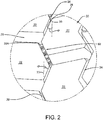
- the tread 20 includes a plurality of tread elements 22 that are defined by angular circumferential grooves 24 and angular lateral grooves 26. More particularly, as shown in Figure 2 , each angular circumferential groove 24 extends about the tire 10 in a circumferential manner according to segments 28 that extend at a first angle ⁇ and a second angle - ⁇ relative to a circumferential direction 30 of the tread 20.
- the first angle ⁇ is from 10 degrees to 30 degrees relative to a circumferential direction 30 of the tread 20, and the second angle - ⁇ is from minus 10 degrees to minus 30 degrees relative to a circumferential direction of the tread.
- Each lateral groove 26 extends laterally across the tread 20 in segments 30. In this manner, the tread elements 22 are staggered and/or angled relative to one another.
- tread wear indicator 50 Formed in a selected one of the circumferential groove segments 28A is an exemplary embodiment of the tread wear indicator of the present invention, indicated generally at 50. It is to be understood that the tread wear indicator 50 may be formed in any one of the circumferential groove segments 28, and that the tire 10 may include more than one tread wear indicator.
- the tread wear indicator 50 extends completely across the selected circumferential groove segment 28A, contacting a first tread element 22A and a second tread element 22B. More particularly, the selected circumferential groove segment 28A and the tread wear indicator 50 are each formed with the same width W. In addition, the selected circumferential groove segment 28A is formed with a length L1. The tread wear indicator 50 is formed with a length L2, which is between 80 percent and 100 percent of the selected groove segment length L1. By being the same width Wand from 80 percent to 100 percent of the length of the selected circumferential groove segment 28A, the tread wear indicator 50 is prominent and easy to read.
- the tread wear indicator 50 preferably is formed with a staircase configuration. More particularly, a plurality of step elements descends from a radially outward surface 34 of the tread 20 toward a bottom or radially inward surface 36 of the selected circumferential groove segment 28A.
- the tread wear indicator 50 includes at least two elements, and preferably four or more elements. As will be described below, each element is similar to the other elements in shape and configuration.
- a first step element 52 includes an axially-extending surface 52A that is approximately parallel to and radially inward of the outward tread surface 34.
- the axially-extending surface 52A is formed with a square or rectangular shape.
- a radially-extending surface 52B extends from the axially-extending surface 52A in an approximately perpendicular manner.
- a second step element 54 includes an axially-extending surface 54A that is parallel to and radially inward of the axially-extending surface 52A of the first step element 52.
- the axially-extending surface 54A is formed with a square or rectangular shape.
- a radially-extending surface 54B extends from the axially-extending surface 54A in an approximately perpendicular manner.
- a third step element 56 includes an axially-extending surface 56A that is parallel to and radially inward of the axially-extending surface 54A of the second step element 54.
- the axially-extending surface 56A is formed with a square or rectangular shape.
- a radially-extending surface 56B extends from the axially-extending surface 56A in an approximately perpendicular manner.
- a fourth step element 58 includes an axially-extending surface 58A that is parallel to and radially inward of the axially-extending surface 56A of the third step element 56.
- the axially-extending surface 58A is formed with a square or rectangular shape.
- a radially-extending surface 58B extends from the axially-extending surface 58A to the bottom 36 of the selected circumferential groove segment 28A in an approximately perpendicular manner.
- each one of the step elements 52, 54, 56 and 58 is based upon the number of steps and the minimum desired indicator height employed for a particular configuration of the tread wear indicator 50.
- the axially-extending surface 58A of the bottom step element 58 preferably is at a minimum desired indicator height. This height may correspond to a recommended minimum tread depth and is based upon particular design considerations for the tire 10.
- the axially-extending surface 58A of the bottom step element 58 may thus be considered to be zero percent of the recommended tread height, while the new, unworn surface 34 of the tread 20 may be considered to be 100 percent of the recommended tread height.
- Each step element 52, 54, 56 and 58 thus is at a set height which corresponds to a specific percentage of the recommended tread height.
- the axially-extending surface 52A of the first step element 52 may be at a height that corresponds to 75 percent of the difference between the height of the axially-extending surface 58A of the fourth step element 58A and the unworn tread surface 34.
- the axially-extending surface 58A of the first step element 58 may thus indicate a level or height at which 75 percent of the recommended tread height remains.
- the axially-extending surface 54A of the second step element 54 may be at a height that corresponds to 50 percent of the difference between the height of the axially-extending surface 58A of the fourth step element 58 and the unworn tread surface 54.
- the axially-extending surface 54A of the second step element 54 may thus indicate a level or height at which 50 percent of the recommended tread height remains.
- the axially-extending surface 56A of the third step element 56 may be at a height that corresponds to 25 percent of the difference between the height of the axially-extending surface 58A of the fourth step element 58 and the unworn tread surface 34.
- the axially-extending surface 56A of the third step element 56 may thus indicate a level or height at which 25 percent of the recommended tread height remains.
- the axially-extending surface 58A of the fourth step element 58 may indicate a height at which 0 percent of the recommended tread height remains and tire replacement should occur.
- Each step element 52, 54, 56 and 58 preferably is formed with indicia 60 for easy identification by a user.
- the axially-extending surface 52A of the first step element 52 preferably is formed with a first number 60A, which is easily seen by a user.
- the axially-extending surface 54A of the second step element 54 preferably is formed with a second number 60B.
- the axially-extending surface 56A of the third step element 56 preferably is formed with a third number 60C.
- the axially-extending surface 58A of the fourth step element 58 preferably is formed with a fourth number 60D.
- the indicia 60 are formed with a distance across the width W of the tread wear indicator 50, which is designated in Figure 3 as D.
- the distance D is from 80 percent to 100 percent of the width W of the tread wear indicator 50.
- the first number 60A is the highest of the indicia 60
- the second number 60B is the second highest
- the third number 60C is the third highest
- the fourth number 60D is the lowest.
- each indicia 60A, 60B, 60C and 60D corresponds to a remaining tread depth in millimeters or 32nds of an inch.
- the tread wear indicator 50 By being formed in the selected circumferential groove segment 28A, the tread wear indicator 50 is easy for a user to see. Also, the tread wear indicator 50 follows the contour of the selected circumferential groove segment 28A and does not interfere with the performance of the tread 20. Moreover, the tread wear indicator 50 is economical to form.
- the tread wear indicator 50 preferably is formed in the tire 10 when the tire is cured.
- the tire 10 is cured in a mold (not shown).
- the tread 20 is formed.
- a die insert is formed with the above-described features of the tread wear indicator.
- the die insert is disposed in a corresponding opening formed in the tire curing mold, and when the tread 20 is formed on the tire 10 during curing, the tread wear indicator 50 is also formed.
- the die insert may be 3D printed, cast or fabricated, and may be formed of any suitable mold material, including steel, aluminum and alloys thereof.
- the present invention also includes a method of forming a tread wear indicator 50 in a tire 10 and a method of using a tread wear indicator in a tire. Each method includes steps in accordance with the description that is presented above and shown in Figures 1 through 4 .
- tread wear indicator 50 may be altered or rearranged, or components or steps known to those skilled in the art omitted or added, without affecting the overall concept or operation of the invention.
- steps or configurations for the step elements 52, 54, 56 and 58 or indicia 60 other than those described above may be employed without affecting the overall concept or operation of the invention.
- the tread wear indicator 50 may be formed in any one of the circumferential groove segments 28, and the tire 10 may include more than one tread wear indicator disposed in different locations and/or alignments.
Landscapes
- Engineering & Computer Science (AREA)
- Mechanical Engineering (AREA)
- Tires In General (AREA)
Claims (14)
- Reifen mit einem Paar Seitenwänden (12, 14), die sich zu einer Lauffläche (20) erstrecken, wobei die Lauffläche (20) mehrere Rillen (24), die Rillensegmente (28A) umfassen, und eine Laufflächenverschleißanzeige (50) beinhaltet, wobei die Laufflächenverschleißanzeige (50) in einem ausgewählten der Rillensegmente (28A) ausgebildet ist und sich vollständig über die Breite des ausgewählten Rillensegments (28A) hinweg erstreckt, wobei die Laufflächenverschleißanzeige (50) mehrere Stufenelemente (52, 54, 56, 58) beinhaltet, die von einer radial nach außen gerichteten Oberfläche der Lauffläche (20) oder der Laufflächenverschleißanzeige (50) zu dem Boden des ausgewählten Rillensegments (28A) hin abfallen, wobei jedes Stufenelement (52, 54, 56, 58) eine erste Oberfläche (52A, 54A, 56A, 58A), die wenigstens ungefähr parallel zu der radial äußersten Oberfläche der Lauffläche (20) ist, und eine sich radial erstreckende zweite Oberfläche (52B, 54B, 56B, 58B) beinhaltet, die sich vorzugsweise wenigstens ungefähr senkrecht zu der ersten Oberfläche (52A, 54A, 56A, 58A) erstreckt, wobei die erste Oberfläche (52A, 54A, 56A, 58A) jedes Stufenelements (52, 54, 56, 58) mit Zeichen (60) ausgebildet ist oder diese umfasst, wobei die gesamten Zeichen (60) für einen Benutzer des Reifens (10) aus einer radial nach außen gerichteten Richtung sichtbar sind, wenn der Reifen nicht verschlissen ist, dadurch gekennzeichnet, dass die Rillensegmente (28A) einen ersten Abschnitt und einen zweiten Abschnitt umfassen, wobei sich die Rillensegmente (28A) in einem ersten Winkel relativ zu einer Umfangsrichtung der Lauffläche (20) in dem ersten Abschnitt und in einem zweiten Winkel relativ zu einer Umfangsrichtung der Lauffläche (20) in dem zweiten Abschnitt erstrecken, wobei der erste Winkel (Θ) in einem Bereich von 10 Grad bis 30 Grad relativ zu einer Umfangsrichtung der Lauffläche (20) liegt und der zweite Winkel (-Θ) in einem Bereich von minus 10 Grad bis minus 30 Grad relativ zu einer Umfangsrichtung der Lauffläche (20) liegt.
- Reifen nach Anspruch 1, wobei die mehreren Rillen mehrere wenigstens im Wesentlichen in Umfangsrichtung ausgerichtete Rillen (24), vorzugsweise winkelförmige Umfangsrillen, sind, und die Rillensegmente (28A) wenigstens im Wesentlichen in Umfangsrichtung ausgerichtete Rillensegmente (28A) sind.
- Reifen nach Anspruch 1 oder 2, wobei die radial äußerste erste Oberfläche (52A) jedes jeweiligen Stufenelements (52, 54, 56, 58) radial nach innen gerichtet von der radial äußersten Oberfläche der Lauffläche (20) liegt.
- Reifen nach wenigstens einem der vorhergehenden Ansprüche, wobei die Laufflächenverschleißanzeige (50) mit einer Länge ausgebildet ist, die in einem Bereich von 80 Prozent bis 100 Prozent einer Länge des ausgewählten Rillensegments (28A) liegt.
- Reifen nach wenigstens einem der vorhergehenden Ansprüche, wobei die Rille (24), die die Rillensegmente (28A) umfasst, eine sich im Wesentlichen in Umfangsrichtung erstreckende zickzackförmige Rille (24) ist.
- Reifen nach wenigstens einem der vorhergehenden Ansprüche, wobei die Zeichen (60) mit einem Abstand (D) über eine Breite der Laufflächenverschleißanzeige (50) hinweg ausgebildet sind, der in einem Bereich von 80 Prozent bis 100 Prozent der Breite der Laufflächenverschleißanzeige (50) liegt.
- Reifen nach wenigstens einem der vorhergehenden Ansprüche, wobei die mehreren Stufenelemente (52, 54, 56, 58) in einer Treppenkonfiguration ausgebildet sind.
- Reifen nach wenigstens einem der vorhergehenden Ansprüche, wobei die erste Oberfläche (52A, 54A, 56A, 58A) jedes Stufenelements (52, 54, 56, 58) eine quadratische oder rechteckige Form aufweist.
- Reifen nach wenigstens einem der vorhergehenden Ansprüche, wobei die Laufflächenverschleißanzeige (50) wenigstens vier Stufenelemente (52, 54, 56, 58) beinhaltet.
- Reifen nach wenigstens einem der vorhergehenden Ansprüche, wobei die erste Oberfläche (52A, 54A, 56A, 58A) jedes Stufenelements (52, 54, 56, 58) in einer Höhe angeordnet ist, die einem ausgewählten Prozentsatz der Laufflächenhöhe des nicht verschlissenen Reifens (10) entspricht.
- Reifen nach wenigstens einem der vorhergehenden Ansprüche, wobei die erste Oberfläche (52A) eines ersten der Stufenelemente (52) in einer Höhe angeordnet ist, die 75 Prozent oder 70 Prozent bis 80 Prozent einer Laufflächenhöhe entspricht, die erste Oberfläche (54A) eines zweiten der Stufenelemente (54) in einer Höhe angeordnet ist, die 50 Prozent oder 40 bis 60 Prozent der Laufflächenhöhe entspricht, die erste Oberfläche (56A) eines dritten der Stufenelemente (56) in einer Höhe angeordnet ist, die 25 Prozent oder 20 Prozent bis 30 Prozent der Laufflächenhöhe entspricht, und die erste Oberfläche (58A) eines vierten der Stufenelemente (58) in einer Höhe angeordnet ist, die null Prozent oder 0 Prozent bis 10 Prozent der Laufflächenhöhe entspricht.
- Reifen nach wenigstens einem der vorhergehenden Ansprüche, wobei die Laufflächenhöhe in dem Fall eines Pkw-Reifens in dem Bereich von 6 bis 9 mm und in dem Fall eines Lkw-Reifens in dem Bereich von 10 bis 16 mm liegt.
- Reifen nach wenigstens einem der vorhergehenden Ansprüche, der mehrere der Laufflächenverschleißanzeigen (50) umfasst, wobei jede in einem jeweilig ausgewählten der Umfangsrillensegmente (28A) ausgebildet ist.
- Verfahren zum Herstellen eines Reifens mit einem Paar von Seitenwänden (12, 14), die sich zu einer Lauffläche (20) erstrecken, wobei die Lauffläche (20) mehrere Rillen (24), die Rillensegmente (28A) umfassen, und eine Laufflächenverschleißanzeige (50) beinhaltet, wobei die Laufflächenverschleißanzeige (50) in einem ausgewählten der Rillensegmente (28A) ausgebildet ist und sich vollständig über die Breite des ausgewählten Rillensegments (28A) hinweg erstreckt, wobei die Laufflächenverschleißanzeige (50) mehrere Stufenelemente (52, 54, 56, 58) beinhaltet, die von einer radial nach außen gerichteten Oberfläche der Lauffläche (20) oder der Laufflächenverschleißanzeige (50) zu dem Boden des ausgewählten Rillensegments (28A) hin abfallen, wobei jedes Stufenelement (52, 54, 56, 58) eine erste Oberfläche (52A, 54A, 56A, 58A), die wenigstens ungefähr parallel zu der radial äußersten Oberfläche der Lauffläche (20) ist, und eine sich radial erstreckende zweite Oberfläche (52B, 54B, 56B, 58B) beinhaltet, die sich vorzugsweise wenigstens ungefähr senkrecht zu der ersten Oberfläche (52A, 54A, 56A, 58A) erstreckt, wobei die erste Oberfläche (52A, 54A, 56A, 58A) jedes Stufenelements (52, 54, 56, 58) mit Zeichen (60) ausgebildet ist oder diese umfasst, wobei die gesamten Zeichen (60) für einen Benutzer des Reifens (10) aus einer radial nach außen gerichteten Richtung sichtbar sind, wenn der Reifen nicht verschlissen ist, wobei die Rillensegmente (28A) einen ersten Abschnitt und einen zweiten Abschnitt umfassen, wobei sich die Rillensegmente (28A) in einem ersten Winkel relativ zu einer Umfangsrichtung der Lauffläche (20) in dem ersten Abschnitt und in einem zweiten Winkel relativ zu einer Umfangsrichtung der Lauffläche (20) in dem zweiten Abschnitte erstrecken, der erste Winkel (Θ) in einem Bereich von 10 Grad bis 30 Grad relativ zu einer Umfangsrichtung der Lauffläche (20) liegt und der zweite Winkel (-Θ) in einem Bereich von minus 10 Grad bis minus 30 Grad relativ zu einer Umfangsrichtung der Lauffläche (20) liegt, wobei das Verfahren den Schritt des Ausbildens der Laufflächenverschleißanzeige (50) mit einem Einsatz umfasst, der in einer Form angeordnet ist, in der der Reifen (10) ausgehärtet wird.
Applications Claiming Priority (1)
| Application Number | Priority Date | Filing Date | Title |
|---|---|---|---|
| US16/227,428 US20200198409A1 (en) | 2018-12-20 | 2018-12-20 | Tire with groove-based tread wear indicator |
Publications (2)
| Publication Number | Publication Date |
|---|---|
| EP3670211A1 EP3670211A1 (de) | 2020-06-24 |
| EP3670211B1 true EP3670211B1 (de) | 2021-11-10 |
Family
ID=69411030
Family Applications (1)
| Application Number | Title | Priority Date | Filing Date |
|---|---|---|---|
| EP19218348.1A Active EP3670211B1 (de) | 2018-12-20 | 2019-12-19 | Reifen mit rillenbasierter laufflächenabnutzungsanzeige |
Country Status (2)
| Country | Link |
|---|---|
| US (1) | US20200198409A1 (de) |
| EP (1) | EP3670211B1 (de) |
Family Cites Families (4)
| Publication number | Priority date | Publication date | Assignee | Title |
|---|---|---|---|---|
| US2706509A (en) * | 1950-04-01 | 1955-04-19 | Gates Rubber Co | Means for indicating tire tread wear |
| FI112340B (fi) * | 1999-06-29 | 2003-11-28 | Nokian Renkaat Oyj | Ajoneuvon renkaan kulutuspinta, jossa on väline kulutuspinnassa olevien urien jokahetkisen syvyyden osoittamiseksi |
| US20110079333A1 (en) * | 2009-10-06 | 2011-04-07 | Jacques Collette | Multi-level tire treadwear indicator |
| US20180326795A1 (en) * | 2017-05-15 | 2018-11-15 | The Goodyear Tire & Rubber Company | Tread wear indicator |
-
2018
- 2018-12-20 US US16/227,428 patent/US20200198409A1/en not_active Abandoned
-
2019
- 2019-12-19 EP EP19218348.1A patent/EP3670211B1/de active Active
Also Published As
| Publication number | Publication date |
|---|---|
| US20200198409A1 (en) | 2020-06-25 |
| EP3670211A1 (de) | 2020-06-24 |
Similar Documents
| Publication | Publication Date | Title |
|---|---|---|
| US20180326795A1 (en) | Tread wear indicator | |
| US20200331301A1 (en) | Tread wear indicator | |
| US7011126B2 (en) | Progressive tire tread wear indicator | |
| EP2455236B1 (de) | Laufflächenabnutzungsindikator | |
| EP2103453B1 (de) | Luftreifen für Schwertransport | |
| US5665184A (en) | Heavy duty pneumatic tire | |
| EP2190680B1 (de) | Reifen mit seitenwandschutz | |
| US20110079333A1 (en) | Multi-level tire treadwear indicator | |
| EP0602989A1 (de) | Luftreifen | |
| JP6286360B2 (ja) | 可変面取り部付きトレッド | |
| CN1197430A (zh) | 带有轮换时间-胎面磨损指示装置的轮胎 | |
| JP6032242B2 (ja) | 更生タイヤ | |
| US10252580B2 (en) | Tread wear indicator | |
| EP3666551B1 (de) | Reifenprofil | |
| US20200346496A1 (en) | Tread wear indicator | |
| US8636045B2 (en) | Tire provided with two protuberances for deflecting lateral expulsions of water | |
| US9211766B2 (en) | Method of designing a tire, and tire | |
| EP3984780B1 (de) | Reifen mit rillenbasierter laufflächenabnutzungsanzeige | |
| JP4933787B2 (ja) | 空気入りタイヤ | |
| EP3674106B1 (de) | Reifen mit integrierter laufflächenabnutzungsanzeige | |
| EP3670211A1 (de) | Reifen mit rillenbasierter laufflächenabnutzungsanzeige | |
| WO2016084985A1 (en) | Tire tread for improving efficiency in mounting operation | |
| US11691458B2 (en) | Tire comprising a tread having grooves with undercut side faces and reinforcing elements | |
| JP6186756B2 (ja) | 空気入りタイヤ | |
| CN112752660A (zh) | 用于标记轮胎的结构和方法 |
Legal Events
| Date | Code | Title | Description |
|---|---|---|---|
| PUAI | Public reference made under article 153(3) epc to a published international application that has entered the european phase |
Free format text: ORIGINAL CODE: 0009012 |
|
| STAA | Information on the status of an ep patent application or granted ep patent |
Free format text: STATUS: THE APPLICATION HAS BEEN PUBLISHED |
|
| AK | Designated contracting states |
Kind code of ref document: A1 Designated state(s): AL AT BE BG CH CY CZ DE DK EE ES FI FR GB GR HR HU IE IS IT LI LT LU LV MC MK MT NL NO PL PT RO RS SE SI SK SM TR |
|
| AX | Request for extension of the european patent |
Extension state: BA ME |
|
| STAA | Information on the status of an ep patent application or granted ep patent |
Free format text: STATUS: REQUEST FOR EXAMINATION WAS MADE |
|
| 17P | Request for examination filed |
Effective date: 20210111 |
|
| RBV | Designated contracting states (corrected) |
Designated state(s): AL AT BE BG CH CY CZ DE DK EE ES FI FR GB GR HR HU IE IS IT LI LT LU LV MC MK MT NL NO PL PT RO RS SE SI SK SM TR |
|
| RIC1 | Information provided on ipc code assigned before grant |
Ipc: B60C 11/24 20060101AFI20210409BHEP |
|
| GRAP | Despatch of communication of intention to grant a patent |
Free format text: ORIGINAL CODE: EPIDOSNIGR1 |
|
| STAA | Information on the status of an ep patent application or granted ep patent |
Free format text: STATUS: GRANT OF PATENT IS INTENDED |
|
| INTG | Intention to grant announced |
Effective date: 20210528 |
|
| GRAS | Grant fee paid |
Free format text: ORIGINAL CODE: EPIDOSNIGR3 |
|
| GRAA | (expected) grant |
Free format text: ORIGINAL CODE: 0009210 |
|
| STAA | Information on the status of an ep patent application or granted ep patent |
Free format text: STATUS: THE PATENT HAS BEEN GRANTED |
|
| AK | Designated contracting states |
Kind code of ref document: B1 Designated state(s): AL AT BE BG CH CY CZ DE DK EE ES FI FR GB GR HR HU IE IS IT LI LT LU LV MC MK MT NL NO PL PT RO RS SE SI SK SM TR |
|
| REG | Reference to a national code |
Ref country code: GB Ref legal event code: FG4D |
|
| REG | Reference to a national code |
Ref country code: AT Ref legal event code: REF Ref document number: 1445754 Country of ref document: AT Kind code of ref document: T Effective date: 20211115 Ref country code: CH Ref legal event code: EP |
|
| REG | Reference to a national code |
Ref country code: DE Ref legal event code: R096 Ref document number: 602019009167 Country of ref document: DE |
|
| REG | Reference to a national code |
Ref country code: IE Ref legal event code: FG4D |
|
| REG | Reference to a national code |
Ref country code: LT Ref legal event code: MG9D |
|
| REG | Reference to a national code |
Ref country code: NL Ref legal event code: MP Effective date: 20211110 |
|
| REG | Reference to a national code |
Ref country code: AT Ref legal event code: MK05 Ref document number: 1445754 Country of ref document: AT Kind code of ref document: T Effective date: 20211110 |
|
| PG25 | Lapsed in a contracting state [announced via postgrant information from national office to epo] |
Ref country code: RS Free format text: LAPSE BECAUSE OF FAILURE TO SUBMIT A TRANSLATION OF THE DESCRIPTION OR TO PAY THE FEE WITHIN THE PRESCRIBED TIME-LIMIT Effective date: 20211110 Ref country code: LT Free format text: LAPSE BECAUSE OF FAILURE TO SUBMIT A TRANSLATION OF THE DESCRIPTION OR TO PAY THE FEE WITHIN THE PRESCRIBED TIME-LIMIT Effective date: 20211110 Ref country code: FI Free format text: LAPSE BECAUSE OF FAILURE TO SUBMIT A TRANSLATION OF THE DESCRIPTION OR TO PAY THE FEE WITHIN THE PRESCRIBED TIME-LIMIT Effective date: 20211110 Ref country code: BG Free format text: LAPSE BECAUSE OF FAILURE TO SUBMIT A TRANSLATION OF THE DESCRIPTION OR TO PAY THE FEE WITHIN THE PRESCRIBED TIME-LIMIT Effective date: 20220210 Ref country code: AT Free format text: LAPSE BECAUSE OF FAILURE TO SUBMIT A TRANSLATION OF THE DESCRIPTION OR TO PAY THE FEE WITHIN THE PRESCRIBED TIME-LIMIT Effective date: 20211110 |
|
| PG25 | Lapsed in a contracting state [announced via postgrant information from national office to epo] |
Ref country code: IS Free format text: LAPSE BECAUSE OF FAILURE TO SUBMIT A TRANSLATION OF THE DESCRIPTION OR TO PAY THE FEE WITHIN THE PRESCRIBED TIME-LIMIT Effective date: 20220310 Ref country code: SE Free format text: LAPSE BECAUSE OF FAILURE TO SUBMIT A TRANSLATION OF THE DESCRIPTION OR TO PAY THE FEE WITHIN THE PRESCRIBED TIME-LIMIT Effective date: 20211110 Ref country code: PT Free format text: LAPSE BECAUSE OF FAILURE TO SUBMIT A TRANSLATION OF THE DESCRIPTION OR TO PAY THE FEE WITHIN THE PRESCRIBED TIME-LIMIT Effective date: 20220310 Ref country code: PL Free format text: LAPSE BECAUSE OF FAILURE TO SUBMIT A TRANSLATION OF THE DESCRIPTION OR TO PAY THE FEE WITHIN THE PRESCRIBED TIME-LIMIT Effective date: 20211110 Ref country code: NO Free format text: LAPSE BECAUSE OF FAILURE TO SUBMIT A TRANSLATION OF THE DESCRIPTION OR TO PAY THE FEE WITHIN THE PRESCRIBED TIME-LIMIT Effective date: 20220210 Ref country code: NL Free format text: LAPSE BECAUSE OF FAILURE TO SUBMIT A TRANSLATION OF THE DESCRIPTION OR TO PAY THE FEE WITHIN THE PRESCRIBED TIME-LIMIT Effective date: 20211110 Ref country code: LV Free format text: LAPSE BECAUSE OF FAILURE TO SUBMIT A TRANSLATION OF THE DESCRIPTION OR TO PAY THE FEE WITHIN THE PRESCRIBED TIME-LIMIT Effective date: 20211110 Ref country code: HR Free format text: LAPSE BECAUSE OF FAILURE TO SUBMIT A TRANSLATION OF THE DESCRIPTION OR TO PAY THE FEE WITHIN THE PRESCRIBED TIME-LIMIT Effective date: 20211110 Ref country code: GR Free format text: LAPSE BECAUSE OF FAILURE TO SUBMIT A TRANSLATION OF THE DESCRIPTION OR TO PAY THE FEE WITHIN THE PRESCRIBED TIME-LIMIT Effective date: 20220211 Ref country code: ES Free format text: LAPSE BECAUSE OF FAILURE TO SUBMIT A TRANSLATION OF THE DESCRIPTION OR TO PAY THE FEE WITHIN THE PRESCRIBED TIME-LIMIT Effective date: 20211110 |
|
| PG25 | Lapsed in a contracting state [announced via postgrant information from national office to epo] |
Ref country code: SM Free format text: LAPSE BECAUSE OF FAILURE TO SUBMIT A TRANSLATION OF THE DESCRIPTION OR TO PAY THE FEE WITHIN THE PRESCRIBED TIME-LIMIT Effective date: 20211110 Ref country code: SK Free format text: LAPSE BECAUSE OF FAILURE TO SUBMIT A TRANSLATION OF THE DESCRIPTION OR TO PAY THE FEE WITHIN THE PRESCRIBED TIME-LIMIT Effective date: 20211110 Ref country code: RO Free format text: LAPSE BECAUSE OF FAILURE TO SUBMIT A TRANSLATION OF THE DESCRIPTION OR TO PAY THE FEE WITHIN THE PRESCRIBED TIME-LIMIT Effective date: 20211110 Ref country code: EE Free format text: LAPSE BECAUSE OF FAILURE TO SUBMIT A TRANSLATION OF THE DESCRIPTION OR TO PAY THE FEE WITHIN THE PRESCRIBED TIME-LIMIT Effective date: 20211110 Ref country code: DK Free format text: LAPSE BECAUSE OF FAILURE TO SUBMIT A TRANSLATION OF THE DESCRIPTION OR TO PAY THE FEE WITHIN THE PRESCRIBED TIME-LIMIT Effective date: 20211110 Ref country code: CZ Free format text: LAPSE BECAUSE OF FAILURE TO SUBMIT A TRANSLATION OF THE DESCRIPTION OR TO PAY THE FEE WITHIN THE PRESCRIBED TIME-LIMIT Effective date: 20211110 |
|
| REG | Reference to a national code |
Ref country code: DE Ref legal event code: R097 Ref document number: 602019009167 Country of ref document: DE |
|
| PG25 | Lapsed in a contracting state [announced via postgrant information from national office to epo] |
Ref country code: MC Free format text: LAPSE BECAUSE OF FAILURE TO SUBMIT A TRANSLATION OF THE DESCRIPTION OR TO PAY THE FEE WITHIN THE PRESCRIBED TIME-LIMIT Effective date: 20211110 |
|
| PLBE | No opposition filed within time limit |
Free format text: ORIGINAL CODE: 0009261 |
|
| STAA | Information on the status of an ep patent application or granted ep patent |
Free format text: STATUS: NO OPPOSITION FILED WITHIN TIME LIMIT |
|
| REG | Reference to a national code |
Ref country code: BE Ref legal event code: MM Effective date: 20211231 |
|
| 26N | No opposition filed |
Effective date: 20220811 |
|
| PG25 | Lapsed in a contracting state [announced via postgrant information from national office to epo] |
Ref country code: LU Free format text: LAPSE BECAUSE OF NON-PAYMENT OF DUE FEES Effective date: 20211219 Ref country code: IE Free format text: LAPSE BECAUSE OF NON-PAYMENT OF DUE FEES Effective date: 20211219 Ref country code: AL Free format text: LAPSE BECAUSE OF FAILURE TO SUBMIT A TRANSLATION OF THE DESCRIPTION OR TO PAY THE FEE WITHIN THE PRESCRIBED TIME-LIMIT Effective date: 20211110 |
|
| PG25 | Lapsed in a contracting state [announced via postgrant information from national office to epo] |
Ref country code: SI Free format text: LAPSE BECAUSE OF FAILURE TO SUBMIT A TRANSLATION OF THE DESCRIPTION OR TO PAY THE FEE WITHIN THE PRESCRIBED TIME-LIMIT Effective date: 20211110 Ref country code: BE Free format text: LAPSE BECAUSE OF NON-PAYMENT OF DUE FEES Effective date: 20211231 |
|
| PG25 | Lapsed in a contracting state [announced via postgrant information from national office to epo] |
Ref country code: CY Free format text: LAPSE BECAUSE OF FAILURE TO SUBMIT A TRANSLATION OF THE DESCRIPTION OR TO PAY THE FEE WITHIN THE PRESCRIBED TIME-LIMIT Effective date: 20211110 |
|
| PG25 | Lapsed in a contracting state [announced via postgrant information from national office to epo] |
Ref country code: HU Free format text: LAPSE BECAUSE OF FAILURE TO SUBMIT A TRANSLATION OF THE DESCRIPTION OR TO PAY THE FEE WITHIN THE PRESCRIBED TIME-LIMIT; INVALID AB INITIO Effective date: 20191219 |
|
| REG | Reference to a national code |
Ref country code: CH Ref legal event code: PL |
|
| PG25 | Lapsed in a contracting state [announced via postgrant information from national office to epo] |
Ref country code: LI Free format text: LAPSE BECAUSE OF NON-PAYMENT OF DUE FEES Effective date: 20221231 Ref country code: CH Free format text: LAPSE BECAUSE OF NON-PAYMENT OF DUE FEES Effective date: 20221231 |
|
| PG25 | Lapsed in a contracting state [announced via postgrant information from national office to epo] |
Ref country code: MK Free format text: LAPSE BECAUSE OF FAILURE TO SUBMIT A TRANSLATION OF THE DESCRIPTION OR TO PAY THE FEE WITHIN THE PRESCRIBED TIME-LIMIT Effective date: 20211110 |
|
| PG25 | Lapsed in a contracting state [announced via postgrant information from national office to epo] |
Ref country code: TR Free format text: LAPSE BECAUSE OF FAILURE TO SUBMIT A TRANSLATION OF THE DESCRIPTION OR TO PAY THE FEE WITHIN THE PRESCRIBED TIME-LIMIT Effective date: 20211110 |
|
| GBPC | Gb: european patent ceased through non-payment of renewal fee |
Effective date: 20231219 |
|
| PG25 | Lapsed in a contracting state [announced via postgrant information from national office to epo] |
Ref country code: MT Free format text: LAPSE BECAUSE OF FAILURE TO SUBMIT A TRANSLATION OF THE DESCRIPTION OR TO PAY THE FEE WITHIN THE PRESCRIBED TIME-LIMIT Effective date: 20211110 |
|
| PG25 | Lapsed in a contracting state [announced via postgrant information from national office to epo] |
Ref country code: GB Free format text: LAPSE BECAUSE OF NON-PAYMENT OF DUE FEES Effective date: 20231219 |
|
| PG25 | Lapsed in a contracting state [announced via postgrant information from national office to epo] |
Ref country code: GB Free format text: LAPSE BECAUSE OF NON-PAYMENT OF DUE FEES Effective date: 20231219 |
|
| PGFP | Annual fee paid to national office [announced via postgrant information from national office to epo] |
Ref country code: DE Payment date: 20251126 Year of fee payment: 7 |
|
| PGFP | Annual fee paid to national office [announced via postgrant information from national office to epo] |
Ref country code: IT Payment date: 20251119 Year of fee payment: 7 |
|
| PGFP | Annual fee paid to national office [announced via postgrant information from national office to epo] |
Ref country code: FR Payment date: 20251120 Year of fee payment: 7 |