EP3670324B1 - Panneau de décompression et ses procédés d'assemblage - Google Patents
Panneau de décompression et ses procédés d'assemblage Download PDFInfo
- Publication number
- EP3670324B1 EP3670324B1 EP19180444.2A EP19180444A EP3670324B1 EP 3670324 B1 EP3670324 B1 EP 3670324B1 EP 19180444 A EP19180444 A EP 19180444A EP 3670324 B1 EP3670324 B1 EP 3670324B1
- Authority
- EP
- European Patent Office
- Prior art keywords
- panel
- annular
- flow path
- decompression
- baffle element
- Prior art date
- Legal status (The legal status is an assumption and is not a legal conclusion. Google has not performed a legal analysis and makes no representation as to the accuracy of the status listed.)
- Active
Links
Images





Classifications
-
- B—PERFORMING OPERATIONS; TRANSPORTING
- B64—AIRCRAFT; AVIATION; COSMONAUTICS
- B64C—AEROPLANES; HELICOPTERS
- B64C1/00—Fuselages; Constructional features common to fuselages, wings, stabilising surfaces or the like
- B64C1/06—Frames; Stringers; Longerons ; Fuselage sections
- B64C1/066—Interior liners
-
- B—PERFORMING OPERATIONS; TRANSPORTING
- B64—AIRCRAFT; AVIATION; COSMONAUTICS
- B64C—AEROPLANES; HELICOPTERS
- B64C1/00—Fuselages; Constructional features common to fuselages, wings, stabilising surfaces or the like
- B64C1/06—Frames; Stringers; Longerons ; Fuselage sections
- B64C1/068—Fuselage sections
- B64C1/069—Joining arrangements therefor
-
- B—PERFORMING OPERATIONS; TRANSPORTING
- B64—AIRCRAFT; AVIATION; COSMONAUTICS
- B64C—AEROPLANES; HELICOPTERS
- B64C1/00—Fuselages; Constructional features common to fuselages, wings, stabilising surfaces or the like
- B64C1/18—Floors
-
- B—PERFORMING OPERATIONS; TRANSPORTING
- B64—AIRCRAFT; AVIATION; COSMONAUTICS
- B64C—AEROPLANES; HELICOPTERS
- B64C1/00—Fuselages; Constructional features common to fuselages, wings, stabilising surfaces or the like
- B64C2001/009—Fuselages; Constructional features common to fuselages, wings, stabilising surfaces or the like comprising decompression panels or valves for pressure equalisation in fuselages or floors
-
- Y—GENERAL TAGGING OF NEW TECHNOLOGICAL DEVELOPMENTS; GENERAL TAGGING OF CROSS-SECTIONAL TECHNOLOGIES SPANNING OVER SEVERAL SECTIONS OF THE IPC; TECHNICAL SUBJECTS COVERED BY FORMER USPC CROSS-REFERENCE ART COLLECTIONS [XRACs] AND DIGESTS
- Y02—TECHNOLOGIES OR APPLICATIONS FOR MITIGATION OR ADAPTATION AGAINST CLIMATE CHANGE
- Y02T—CLIMATE CHANGE MITIGATION TECHNOLOGIES RELATED TO TRANSPORTATION
- Y02T50/00—Aeronautics or air transport
- Y02T50/40—Weight reduction
Definitions
- the field of the present disclosure relates generally to aircraft sidewall panel assemblies and, more specifically, to decompression panel assemblies for use in aircraft assemblies.
- the cabin sidewalls include decompression panels or decompression grills that restrict such airflow in standard operation and enable the airflow during a decompression event.
- Known decompression panels are solid panels and move to create an opening in the sidewall. At least some known decompression panels swing into the space between the sidewall and fuselage skin during a decompression event. However, at least some such known decompression panels are heavier than alternatives and include an electronically connected or pressure sensitive mechanical latch systems and also require a relatively large volume between the passenger cabin and the skin of the aircraft to deploy.
- At least some alternative known decompression grilles include an opening having louvers or have several openings through the grille. These openings allow air to flow through the grille during a decompression event so the grille does not move during the decompression event.
- a sound attenuating material a.k.a., a baffle
- the baffle is only connected to the grille at discrete points, which may cause the baffle to resonate and transfer noise to the cabin.
- louvered configurations provide for a larger dust accumulation surface, and have a greater potential for passenger abuse, trash trap, and noise transmission than desired.
- the decompression panel assembly includes a panel comprising an opening defined therein, a vent cover coupled across the opening, and a latching mechanism.
- the vent cover is configured to move between a first position and a second position.
- the latching mechanism is configured to maintain the vent cover in the first position when a pressure differential across the panel is below a predetermined value and facilitate the vent cover moving to the second position when the pressure differential across the panel exceeds the predetermined value.
- a decompression panel assembly for use in an aircraft includes a frame including a first surface and an opposing second surface, wherein the frame defines a grille opening and at least partially defines a flow path opening.
- the decompression panel assembly also includes a face panel having a first surface retained against the frame second surface such that the face panel at least partially covers the grille opening.
- a retention mechanism is coupled to the face panel and is configured to retain the face panel against the frame in a closed position.
- decompression panel assembly as defined in claim 1.
- the decompression panel assembly includes a first annular baffle element coupled to a first panel and a second panel such that the first baffle element forms a seal between the first panel and the second panel.
- the decompression panel assembly also includes a second annular baffle element coupled to the second panel and a third panel such that the second baffle element forms a seal between the second panel and the third panel.
- the method includes defining a first annular flow path between a cover panel and spacer panel and defining a second annular flow path between the spacer panel and a body panel, wherein the second flow path circumscribes the first flow path.
- the method also includes preventing airflow through the first annular flow path with a first baffle element during a first operating condition and channeling airflow through the first annular flow path in a second operating condition.
- the embodiments illustrated herein describe a decompression panel assembly having a cover panel positioned in an opening in a body panel to define a gap around the cover panel.
- An annular spacer panel is positioned outboard from the cover panel and the body panel to define a first annular flow path between the cover panel and the spacer panel and a second annular flow path between the body panel and the spacer panel.
- the body, cover, and spacer panels are designed to closely match each other in texture and color and to match the rest of the cabin interior to improve the visual characteristics of the aircraft sidewall assembly.
- the decompression panel assembly also includes a first louver member coupled within the first flow path and a second louver member coupled within the second flow path.
- the louver members are positioned behind the cover panel and body panel, respectively, and out of view from within the aircraft cabin. Positioning the louver members in such a configuration reduces accessibility to passengers and thus minimizes the potential for passenger abuse. Additionally, the louver members are hidden from view to prevent passengers from seeing any potential unsightly buildup of dust on the louver members.
- the decompression panel assembly also includes a first baffle element is coupled to the cover panel and spacer panel to selectively seal the first flow path, and a second baffle element is coupled to the body panel and the spacer panel to selectively seal the second flow path.
- the baffle elements are continuously attached to their respective panels about their entire circumference to form an air-tight seal. During standard operations, the seals prevent airflow along either of the flow paths to reduce or prevent noise generated by vibrations caused by airflow leakage. Additionally, the baffle elements use an adhesive to bond to the panels rather than a releasable mechanical fastener, which reduces the weight and costs of the decompression panel assembly.
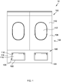
- FIG. 1 is a front view of an inboard configuration of an exemplary cabin 100 that may be used with an aircraft 10.
- FIG. 2 is a rear view of an outboard configuration of the aircraft cabin including the decompression panel assembly shown in FIG. 1 .
- cabin 100 includes a sidewall assembly 102, a floor panel 104, and a decompression panel assembly 106 coupled therebetween.
- Sidewall assembly 102, floor panel 104, and decompression panel assembly 106 at least partially define an interior 108 of cabin 100.
- Sidewall assembly 102 includes a sidewall 110 having a window opening 112 defined therein. Alternatively, sidewall 110 does not include window opening 112.
- decompression panel assembly 106 facilitates equalizing the pressure in cabin 100 during a decompression event.
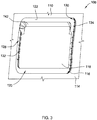
- Decompression panel assembly 106 includes a body panel 114 having an opening 116 defined therein.
- a cover panel 118 is positioned within opening 116 and spaced from body panel 114 such that an annular gap 120 is defined between cover panel 118 and body panel 114 about a perimeter of cover panel 118.
- Decompression panel assembly 106 also includes an annular spacer panel 122 positioned outboard from cover panel 118 and body panel 114.
- annular spacer panel 122 is annular in shape and spans annular gap 120 such that annular spacer panel 122 partially overlaps both cover panel 118 and body panel 114. As shown in FIG.
- cover panel 118 and annular spacer panel 122 are visible from cabin 100 and so are designed to blend in with body panel 114. More specifically, cover panel 118, annular spacer panel 122, and body panel 114 are formed from a substantially similar material and are substantially the same color so as to appear as a single solid panel from within cabin 100.
- FIG. 2 shows an outboard side of decompression panel assembly 106 and illustrates a first baffle element 124 coupled to cover panel 118 and to spacer panel 122. Additionally, a second baffle element 126 is coupled to spacer panel 122 and to body panel 114. As shown in FIG. 2 , first baffle element 124 and second baffle element 126 are annular in shape and are concentric such that second baffle element 126 circumscribes first baffle element 124.
- FIG. 3 is a perspective inboard view of decompression panel assembly 106.
- FIG. 4 is a perspective outboard view of decompression panel assembly 106.
- FIG. 5 is a side cross-sectional view of decompression panel assembly 106 taken along line 5-5 shown in FIG. 2 .
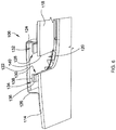
- FIG. 6 is a perspective cross-sectional view of decompression panel assembly 106 at a first location.
- FIG. 7 is a perspective cross-sectional view of decompression panel assembly 106 at a second location.
- FIG. 8 is an exploded view of decompression panel assembly 106.
- Spacer panel 122 is spaced from cover panel 118 to define a first annular flow path 128 between cover panel 118 and spacer panel 122. Further, spacer panel 122 is spaced from body panel 114 to define a second annular flow path 130 between body panel 114 and spacer panel 122. As described herein, second flow path 130 circumscribes first flow path 128 and the two flow paths are designed to combine to channel a high volume of air therethrough during a decompression event while each remains relatively small in size to occupy a minimal amount of space. As best shown in FIGs 5 and 6 , decompression panel assembly 106 includes a first louver member 132 coupled between cover panel 118 and spacer panel 122 and positioned within first flow path 128.
- decompression panel assembly 106 also includes a second louver member 134 coupled between cover panel 118 and spacer panel 122 and positioned within first flow path 128.
- Louver members 132 and 134 each include a ring-shaped element 136 positioned between spacer panel 122 and body panel 114 in the case of second louver member 134, and between cover panel 118 and spacer panel 122, in the case of first louver member 132.
- each louver member 132 and 134 includes support members 138 that are coupled to and extend between spacer panel 122 and body panel 114 in the case of second louver member 134, and between cover panel 118 and spacer panel 122 in the case of first louver member 132.
- louver member 132 and 134 couple spacer panel 122 to cover panel 118 and body panel 114 and facilitate guiding airflow through flow paths 128 and 130.
- louver members 132 and 134 are annular in shape such that second louver member 134 is concentric with and circumscribes first louver member 132.
- first louver member 132 couples cover panel 118 to spacer panel 122 and is positioned inside of an outer perimeter 140 of cover panel 118 such that first louver member 132 is hidden from view from inside cabin 100.
- second louver member 134 couples body panel 114 to spacer panel 122 and is positioned about a circumference of opening 116 of body panel 114 such that second louver member 134 is also hidden from view from inside cabin 100.
- the surfaces of support members 138 of louver members 132 and 134 may accumulate dust and so positioning them behind cover panel 118 and body panel 114 removes them from view of a passenger to improve aesthetics and also reduces the potential for passenger abuse.
- cover panel 118 includes a curved top portion 142 that curves towards spacer panel 122.
- curved top portion 142 contacts spacer panel 122 to restrict a portion of first flow path 128.
- curved top portion 142 extends close to, but does not contact, spacer panel 122.
- curved top portion 142 restricts a portion of first flow path 128 to reduce debris accumulation on first louver member 132. Curved top portion 142 causes any debris placed there by a passenger to slide back into interior 108 of cabin 100 rather than becoming lodged in first louver member 132.
- first baffle element 124 is coupled to cover panel 118 and to spacer panel 122 and is annular in shape such that first baffle element 124 forms a seal between cover panel 118 and to spacer panel 122 to selectively seal first flow path 128 in a first operating condition of aircraft 10.
- second baffle element 126 is coupled to body panel 114 and to spacer panel 122 and is annular in shape such that second baffle element 126 forms a seal between body panel 114 and to spacer panel 122 to selectively seal second flow path 130 in a first operating condition of aircraft 10.
- baffle elements 124 and 126 are coupled to corresponding panels 118, 122, and 114 using a pressure sensitive adhesive that forms an air-tight seal across first flow path 128 and second flow path 130.
- Baffle elements 124 and 126 both include a plurality of designated fracture zones 144 that form lines of weakness configured to tear during a decompression event to enable airflow through first flow path 128 between cover panel 118 and spacer panel 122 and through second flow path 130 between body panel 114 and spacer panel 122..
- first baffle element 124 is coupled to cover panel 118 and spacer panel 122 about an entire circumference of first flow path 128 to prevent airflow through first flow path 128 during standard operating conditions.
- second baffle element 126 is coupled to body panel 114 and spacer panel 122 about an entire circumference of second flow path 130 to prevent airflow through second flow path 130 during standard operating conditions.
- baffle elements 124 and 126 are coupled to corresponding panels 118, 122, and 114 using an adhesive that forms an air-tight seal along first and second flow paths 128 and 130.
- baffle elements 124 and 126 are coupled to corresponding panels 118, 122, and 114 using any means that results in an air-tight seal along first and second flow paths 128 and 130. The air-tight seal results in reduced or eliminated noise transmission.
- a pressure differential between cabin interior 108 and an environment outside of interior 108 causes first baffle element 124 and second baffle element 126 to tear or fragment along pre-formed designated fracture zones 144 to enable channeling of an airflow through the first flow path 128 and the second flow path 130.
- the amount of designated fracture zones 144 is sufficient to cause first baffle element 124 and second baffle element 126 to tear into small enough pieces so as to not block first flow path 128 and the second flow path 130.
- FIG. 9 is a flow chart of a method 200 of assembling decompression panel assembly 106 in aircraft 10.
- Method 200 includes positioning 202 cover panel 118 within opening 116 defined in body panel 114 such that annular gap 120 is defined between body panel 114 and cover panel 118.
- method 200 includes positioning 204 annular spacer panel 122 outboard from cover panel 118 and body panel 114 such that annular spacer panel 122 spans annular gap 120 and such that spacer panel 122 is spaced from cover panel 118 to define first flow path 128 between cover panel 118 and spacer panel 122 and to define second flow path 130 between body panel 114 and spacer panel 122.
- Method 200 also includes coupling 206 first annular louver member 132 between cover panel 118 and spacer panel 122 within first flow path 128 and coupling 208 second annular louver member 134 between body panel 114 and spacer panel 122 within second flow path 130.
- Coupling 208 second annular louver member 134 includes coupling second louver member 134 such that second annular louver member 134 circumscribes first annular louver member 132.
- Method 200 also includes coupling 210 first baffle element 124 to cover panel 118 and to spacer panel 122 to selectively seal first flow path 128 and coupling 212 second baffle element 126 to body panel 114 and to spacer panel 122 to selectively seal second flow path 130.
- Coupling 212 second baffle element 126 includes coupling second baffle element 126 such that second baffle element 126 circumscribes first baffle element 124.
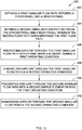
- FIG. 10 is a flow chart of a method 300 of providing a decompression flow path in aircraft 10.
- Method 300 includes defining 302 first annular flow path 128 between cover panel 118 and spacer panel 122 and defining 304 second annular flow path 130 between spacer panel 122 and body panel 114, wherein second flow path 130 is concentric with and circumscribes first flow path 128.
- Method 300 also includes preventing 306 airflow through first flow path 128 with first baffle element 124 during a first operating condition and channeling 308 airflow through first annular flow path 128 in a second operating condition.
- Channelling 308 airflow through first flow path 128 includes removing first baffle element 124 from first flow path 128, wherein removing first baffle element 124 includes fragmenting first baffle element 124 along fracture zones 144, which care pre-formed in baffle elements 124 and 126, during the second operating condition.
- Method 300 also includes preventing 310 airflow through second flow path 130 with second baffle element 126 during the first operating condition and channeling 312 airflow through second flow path 130 in the second operating condition.
- channeling 312 airflow through second flow path 130 includes removing second baffle element 126 from second flow path 130.
- the embodiments illustrated herein describe a decompression panel assembly having a cover panel positioned in an opening in a body panel to define a gap around the cover panel.
- An spacer panel which is annular in shape, is positioned outboard from the cover panel and the body panel to define a first flow path between the cover panel and the spacer panel and a second flow path between the body panel and the spacer panel, wherein the first and second flow paths are also annular in shape.
- the body, cover, and spacer panels are designed to closely match each other in texture and color and to match the rest of the cabin interior to improve the visual characteristics of the aircraft sidewall assembly.
- the decompression panel assembly also includes a first louver member coupled within the first flow path and a second louver member coupled within the second flow path.
- the louver members are positioned behind the cover panel and body panel, respectively, and out of view from within the aircraft cabin. Positioning the louver members in such a configuration reduces accessibility to passengers and thus minimizes the potential for passenger abuse. Additionally, the louver members are hidden from view to prevent passengers from seeing any potential unsightly buildup of dust on the louver members
- the decompression panel assembly also includes a first baffle element is coupled to the cover panel and spacer panel to selectively seal the first flow path, and a second baffle element is coupled to the body panel and the spacer panel to selectively seal the second flow path.
- the baffle elements are continuously attached to their respective panels about their entire circumference to form an air-tight seal. During standard operations, the seals prevent airflow along either of the flow paths to reduce or prevent noise generated by vibrations cause by airflow leakage in some known assemblies. Additionally, the baffle elements use an adhesive to bond to the panels rather than a releasable mechanical fastener, which reduces the weight and costs of the decompression panel assembly.
Landscapes
- Engineering & Computer Science (AREA)
- Mechanical Engineering (AREA)
- Aviation & Aerospace Engineering (AREA)
- Securing Of Glass Panes Or The Like (AREA)
- Air-Conditioning For Vehicles (AREA)
Claims (15)
- Ensemble panneau de décompression (106) destiné à être utilisé dans une cabine (100) d'aéronef, ledit ensemble panneau de décompression (106) définissant au moins partiellement un intérieur (108) de la cabine (100) et comprenant :un panneau formant corps (114) dans lequel est ménagée une ouverture (116) ;un panneau formant cache (118) positionné à l'intérieur de ladite ouverture (116) et espacé dudit panneau formant corps (114) ;un panneau formant espaceur annulaire (122) positionné côté extérieur dudit panneau formant cache (118) et dudit panneau formant corps (114), ledit panneau formant espaceur annulaire (122) étant espacé dudit panneau formant cache (118) pour ménager un premier chemin d'écoulement annulaire (128) entre ledit panneau formant cache (118) et ledit panneau formant espaceur annulaire (122), et ledit panneau formant espaceur annulaire (122) étant espacé dudit panneau formant corps (114) pour ménager un deuxième chemin d'écoulement annulaire (130) entre ledit panneau formant corps (114) et ledit panneau formant espaceur annulaire ;un premier élément déflecteur (124) accouplé audit panneau formant cache (118) et audit panneau formant espaceur annulaire (122) et configuré pour obturer hermétiquement de façon sélective ledit premier chemin d'écoulement annulaire (128) ; etun deuxième élément déflecteur (126) accouplé audit panneau formant corps (114) et audit panneau formant espaceur annulaire (122) et configuré pour obturer hermétiquement de façon sélective ledit deuxième chemin d'écoulement annulaire (130) ;ledit premier élément déflecteur (124) et ledit deuxième élément déflecteur (126) comprenant chacun une pluralité de zones de fracture désignées (144) configurées pour se déchirer au cours d'un événement de décompression pour laisser passer un écoulement d'air à travers ledit premier chemin d'écoulement annulaire (128) et ledit deuxième chemin d'écoulement annulaire (130).
- Ensemble panneau de décompression (106) selon la revendication 1, dans lequel un intervalle annulaire (120) est ménagé entre ledit panneau formant cache (118) et ledit panneau formant corps (114), et dans lequel ledit panneau formant espaceur annulaire (122) couvre ledit intervalle annulaire.
- Ensemble panneau de décompression (106) selon la revendication 1 ou 2, comprenant en outre un premier organe formant persienne (132) accouplé entre ledit panneau formant cache (118) et ledit panneau formant espaceur annulaire (122) et positionné au sein dudit premier chemin d'écoulement annulaire (128), ledit premier organe formant persienne (132) étant de forme de préférence annulaire.
- Ensemble panneau de décompression (106) selon la revendication 3, comprenant en outre un deuxième organe formant persienne (134) accouplé entre ledit panneau formant corps (114) et ledit panneau formant espaceur annulaire (122) et positionné au sein dudit deuxième chemin d'écoulement annulaire (130), ledit premier organe formant persienne (132) et ledit deuxième organe formant persienne (134) étant de forme de préférence annulaire et ledit deuxième organe formant persienne encadrant ledit premier organe formant persienne.
- Ensemble panneau de décompression (106) selon l'une quelconque des revendications 1 à 4, dans lequel ledit premier élément déflecteur (124) et ledit deuxième élément déflecteur (126) sont annulaires.
- Ensemble panneau de décompression (106) selon la revendication 5, dans lequel ledit deuxième élément déflecteur (126) encadre ledit premier élément déflecteur (124).
- Ensemble panneau de décompression (106) selon l'une quelconque des revendications 1 à 6, dans lequel ledit panneau formant cache (118) comprend une partie supérieure incurvée (142) qui vient au contact dudit panneau formant espaceur annulaire (122).
- Ensemble panneau de décompression (106) selon l'une quelconque des revendications 1 à 7, dans lequel ledit premier élément déflecteur (124) et ledit deuxième élément déflecteur (126) sont accouplés au moyen d'un adhésif.
- Ensemble panneau de décompression (106) selon la revendication 8, dans lequel ledit adhésif est configuré pour former un joint hermétique étanche à l'air le long des premier et deuxième chemins d'écoulement (128, 130).
- Procédé (200) d'assemblage d'un ensemble panneau de décompression destiné à être utilisé dans une cabine d'aéronef, ledit ensemble panneau de décompression (106) définissant au moins partiellement un intérieur (108) de la cabine (100), ledit procédé comprenant :le positionnement (202) d'un panneau formant cache à l'intérieur d'une ouverture ménagée dans un panneau formant corps de façon à ménager un intervalle annulaire entre le panneau formant corps et le panneau formant cache ; etle positionnement (204) d'un panneau formant espaceur annulaire côté extérieur du panneau formant cache et du panneau formant corps de façon à ce que le panneau formant espaceur couvre l'intervalle annulaire et soit espacé du panneau formant cache pour ménager un premier chemin d'écoulement entre le panneau formant cache et le panneau formant espaceur et pour ménager un deuxième chemin d'écoulement entre le panneau formant corps et le panneau formant espaceur ;l'accouplement (210) d'un premier élément déflecteur au panneau formant cache et au panneau formant espaceur pour obturer hermétiquement de façon sélective le premier chemin d'écoulement ; etl'accouplement d'un deuxième élément déflecteur au panneau formant corps et au panneau formant espaceur pour obturer hermétiquement de façon sélective le deuxième chemin d'écoulement ;ledit premier élément déflecteur (124) et ledit deuxième élément déflecteur (126) comprenant chacun une pluralité de zones de fracture désignées (144) configurées pour se déchirer au cours d'un événement de décompression pour laisser passer un écoulement d'air à travers ledit premier chemin d'écoulement annulaire (128) et ledit deuxième chemin d'écoulement annulaire (130).
- Procédé (200) selon la revendication 10, comprenant en outre l'accouplement (206) d'un premier organe annulaire formant persienne entre le panneau formant cache et le panneau formant espaceur au sein du premier chemin d'écoulement.
- Procédé (200) selon la revendication 11, comprenant en outre l'accouplement (208) d'un deuxième organe annulaire formant persienne entre le panneau formant corps et le panneau formant espaceur au sein du deuxième chemin d'écoulement.
- Procédé (200) selon la revendication 12, dans lequel l'accouplement (208) du deuxième organe annulaire formant persienne comprend l'accouplement du deuxième organe formant persienne de façon à ce que le deuxième organe annulaire formant persienne encadre le premier organe annulaire formant persienne.
- Procédé (200) selon la revendication 10, dans lequel l'accouplement (212) du deuxième élément déflecteur comprend l'accouplement du deuxième élément déflecteur de façon à ce que le deuxième élément déflecteur encadre le premier élément déflecteur.
- Procédé selon l'une quelconque des revendications 10 à 14, dans lequel ledit premier élément déflecteur (124) et ledit deuxième élément déflecteur (126) sont accouplés au moyen d'un adhésif.
Applications Claiming Priority (1)
| Application Number | Priority Date | Filing Date | Title |
|---|---|---|---|
| US16/225,208 US10926860B2 (en) | 2018-12-19 | 2018-12-19 | Decompression panel assembly and methods of assembling the same |
Publications (2)
| Publication Number | Publication Date |
|---|---|
| EP3670324A1 EP3670324A1 (fr) | 2020-06-24 |
| EP3670324B1 true EP3670324B1 (fr) | 2021-12-08 |
Family
ID=66912629
Family Applications (1)
| Application Number | Title | Priority Date | Filing Date |
|---|---|---|---|
| EP19180444.2A Active EP3670324B1 (fr) | 2018-12-19 | 2019-06-17 | Panneau de décompression et ses procédés d'assemblage |
Country Status (2)
| Country | Link |
|---|---|
| US (1) | US10926860B2 (fr) |
| EP (1) | EP3670324B1 (fr) |
Families Citing this family (1)
| Publication number | Priority date | Publication date | Assignee | Title |
|---|---|---|---|---|
| US11014678B2 (en) * | 2018-04-25 | 2021-05-25 | Roberto Antonio Ogarrio | Aircraft window plug device |
Family Cites Families (7)
| Publication number | Priority date | Publication date | Assignee | Title |
|---|---|---|---|---|
| DE102009012015A1 (de) | 2009-03-06 | 2010-09-09 | Airbus Deutschland Gmbh | Dekompressionsanordnung für ein Luftfahrzeug |
| US8240604B2 (en) * | 2009-12-14 | 2012-08-14 | Be Intellectual Property, Inc. | Fireproof bidirectional decompression panel |
| US9440744B2 (en) | 2013-10-17 | 2016-09-13 | The Boeing Company | Decompression panel assembly and method of equalizing air pressure differential |
| US9499251B2 (en) | 2013-10-25 | 2016-11-22 | The Boeing Company | Decompression panel for use in an aircraft |
| US10071795B2 (en) | 2013-10-25 | 2018-09-11 | The Boeing Company | Clamp device for use with a decompression panel in an aircraft assembly |
| US9611028B2 (en) * | 2014-01-17 | 2017-04-04 | William J. Boyer | Pressure relief panel guard |
| US10399660B2 (en) | 2016-06-06 | 2019-09-03 | The Boening Company | Decompression panel assembly and methods of assembling the same |
-
2018
- 2018-12-19 US US16/225,208 patent/US10926860B2/en active Active
-
2019
- 2019-06-17 EP EP19180444.2A patent/EP3670324B1/fr active Active
Also Published As
| Publication number | Publication date |
|---|---|
| US10926860B2 (en) | 2021-02-23 |
| US20200198759A1 (en) | 2020-06-25 |
| EP3670324A1 (fr) | 2020-06-24 |
Similar Documents
| Publication | Publication Date | Title |
|---|---|---|
| US10399660B2 (en) | Decompression panel assembly and methods of assembling the same | |
| US6264141B1 (en) | Aircraft decompression protection panel | |
| US9233747B2 (en) | Decompression panel for use in an aircraft assembly | |
| US5871178A (en) | Decompression panel for aircraft partition | |
| US7654487B2 (en) | Vent baffle | |
| US20100216384A1 (en) | Air extractors | |
| CA2784011C (fr) | Panneau de decompression bidirectionnelle resistant au feu | |
| EP0905018A3 (fr) | Ensemble de décompression pour avion | |
| US9566759B2 (en) | Decompression panel for use in an aircraft assembly | |
| CN109941104A (zh) | 具有集成在仪表板中的平视显示器的交通工具 | |
| US20170129581A1 (en) | Sidewall panel assembly and return air bridge for use in an aircraft assembly | |
| US10899428B2 (en) | Decompression panel assembly and methods of installation | |
| US10926860B2 (en) | Decompression panel assembly and methods of assembling the same | |
| US20160031312A1 (en) | Co-injected sealing structure of an air recirculation prevention device | |
| JP4661515B2 (ja) | 車両用ドア構造 | |
| KR101659445B1 (ko) | 차량용 방충망 세트 | |
| CA2964252C (fr) | Assemblage de panneau de decompression et methodes d'assemblage associees | |
| BR102015012457A2 (pt) | Truck cabin cover with noise absorber. | |
| WO2010113967A1 (fr) | Structure de prévention du bruit du vent pour véhicule | |
| CN112549923B (zh) | 片材、门孔密封件及其制造方法 | |
| JP6087221B2 (ja) | 車両用換気装置 | |
| US12128738B2 (en) | Cabin air extraction assembly and method for a vehicle | |
| JPH0834224A (ja) | エアバッグ装着車用ドラフタ及びドラフタの取付構造 | |
| JP2007106281A (ja) | 車両用ドア構造 | |
| US20160068038A1 (en) | Body vent protector |
Legal Events
| Date | Code | Title | Description |
|---|---|---|---|
| PUAI | Public reference made under article 153(3) epc to a published international application that has entered the european phase |
Free format text: ORIGINAL CODE: 0009012 |
|
| STAA | Information on the status of an ep patent application or granted ep patent |
Free format text: STATUS: REQUEST FOR EXAMINATION WAS MADE |
|
| 17P | Request for examination filed |
Effective date: 20190617 |
|
| AK | Designated contracting states |
Kind code of ref document: A1 Designated state(s): AL AT BE BG CH CY CZ DE DK EE ES FI FR GB GR HR HU IE IS IT LI LT LU LV MC MK MT NL NO PL PT RO RS SE SI SK SM TR |
|
| AX | Request for extension of the european patent |
Extension state: BA ME |
|
| GRAP | Despatch of communication of intention to grant a patent |
Free format text: ORIGINAL CODE: EPIDOSNIGR1 |
|
| STAA | Information on the status of an ep patent application or granted ep patent |
Free format text: STATUS: GRANT OF PATENT IS INTENDED |
|
| INTG | Intention to grant announced |
Effective date: 20210702 |
|
| GRAS | Grant fee paid |
Free format text: ORIGINAL CODE: EPIDOSNIGR3 |
|
| GRAA | (expected) grant |
Free format text: ORIGINAL CODE: 0009210 |
|
| STAA | Information on the status of an ep patent application or granted ep patent |
Free format text: STATUS: THE PATENT HAS BEEN GRANTED |
|
| AK | Designated contracting states |
Kind code of ref document: B1 Designated state(s): AL AT BE BG CH CY CZ DE DK EE ES FI FR GB GR HR HU IE IS IT LI LT LU LV MC MK MT NL NO PL PT RO RS SE SI SK SM TR |
|
| REG | Reference to a national code |
Ref country code: GB Ref legal event code: FG4D |
|
| REG | Reference to a national code |
Ref country code: AT Ref legal event code: REF Ref document number: 1453582 Country of ref document: AT Kind code of ref document: T Effective date: 20211215 Ref country code: CH Ref legal event code: EP |
|
| REG | Reference to a national code |
Ref country code: DE Ref legal event code: R096 Ref document number: 602019009827 Country of ref document: DE |
|
| REG | Reference to a national code |
Ref country code: IE Ref legal event code: FG4D |
|
| REG | Reference to a national code |
Ref country code: LT Ref legal event code: MG9D |
|
| REG | Reference to a national code |
Ref country code: NL Ref legal event code: MP Effective date: 20211208 |
|
| PG25 | Lapsed in a contracting state [announced via postgrant information from national office to epo] |
Ref country code: RS Free format text: LAPSE BECAUSE OF FAILURE TO SUBMIT A TRANSLATION OF THE DESCRIPTION OR TO PAY THE FEE WITHIN THE PRESCRIBED TIME-LIMIT Effective date: 20211208 Ref country code: LT Free format text: LAPSE BECAUSE OF FAILURE TO SUBMIT A TRANSLATION OF THE DESCRIPTION OR TO PAY THE FEE WITHIN THE PRESCRIBED TIME-LIMIT Effective date: 20211208 Ref country code: FI Free format text: LAPSE BECAUSE OF FAILURE TO SUBMIT A TRANSLATION OF THE DESCRIPTION OR TO PAY THE FEE WITHIN THE PRESCRIBED TIME-LIMIT Effective date: 20211208 Ref country code: BG Free format text: LAPSE BECAUSE OF FAILURE TO SUBMIT A TRANSLATION OF THE DESCRIPTION OR TO PAY THE FEE WITHIN THE PRESCRIBED TIME-LIMIT Effective date: 20220308 |
|
| REG | Reference to a national code |
Ref country code: AT Ref legal event code: MK05 Ref document number: 1453582 Country of ref document: AT Kind code of ref document: T Effective date: 20211208 |
|
| PG25 | Lapsed in a contracting state [announced via postgrant information from national office to epo] |
Ref country code: SE Free format text: LAPSE BECAUSE OF FAILURE TO SUBMIT A TRANSLATION OF THE DESCRIPTION OR TO PAY THE FEE WITHIN THE PRESCRIBED TIME-LIMIT Effective date: 20211208 Ref country code: NO Free format text: LAPSE BECAUSE OF FAILURE TO SUBMIT A TRANSLATION OF THE DESCRIPTION OR TO PAY THE FEE WITHIN THE PRESCRIBED TIME-LIMIT Effective date: 20220308 Ref country code: LV Free format text: LAPSE BECAUSE OF FAILURE TO SUBMIT A TRANSLATION OF THE DESCRIPTION OR TO PAY THE FEE WITHIN THE PRESCRIBED TIME-LIMIT Effective date: 20211208 Ref country code: HR Free format text: LAPSE BECAUSE OF FAILURE TO SUBMIT A TRANSLATION OF THE DESCRIPTION OR TO PAY THE FEE WITHIN THE PRESCRIBED TIME-LIMIT Effective date: 20211208 Ref country code: GR Free format text: LAPSE BECAUSE OF FAILURE TO SUBMIT A TRANSLATION OF THE DESCRIPTION OR TO PAY THE FEE WITHIN THE PRESCRIBED TIME-LIMIT Effective date: 20220309 Ref country code: ES Free format text: LAPSE BECAUSE OF FAILURE TO SUBMIT A TRANSLATION OF THE DESCRIPTION OR TO PAY THE FEE WITHIN THE PRESCRIBED TIME-LIMIT Effective date: 20211208 |
|
| PG25 | Lapsed in a contracting state [announced via postgrant information from national office to epo] |
Ref country code: NL Free format text: LAPSE BECAUSE OF FAILURE TO SUBMIT A TRANSLATION OF THE DESCRIPTION OR TO PAY THE FEE WITHIN THE PRESCRIBED TIME-LIMIT Effective date: 20211208 |
|
| PG25 | Lapsed in a contracting state [announced via postgrant information from national office to epo] |
Ref country code: SM Free format text: LAPSE BECAUSE OF FAILURE TO SUBMIT A TRANSLATION OF THE DESCRIPTION OR TO PAY THE FEE WITHIN THE PRESCRIBED TIME-LIMIT Effective date: 20211208 Ref country code: SK Free format text: LAPSE BECAUSE OF FAILURE TO SUBMIT A TRANSLATION OF THE DESCRIPTION OR TO PAY THE FEE WITHIN THE PRESCRIBED TIME-LIMIT Effective date: 20211208 Ref country code: RO Free format text: LAPSE BECAUSE OF FAILURE TO SUBMIT A TRANSLATION OF THE DESCRIPTION OR TO PAY THE FEE WITHIN THE PRESCRIBED TIME-LIMIT Effective date: 20211208 Ref country code: PT Free format text: LAPSE BECAUSE OF FAILURE TO SUBMIT A TRANSLATION OF THE DESCRIPTION OR TO PAY THE FEE WITHIN THE PRESCRIBED TIME-LIMIT Effective date: 20220408 Ref country code: EE Free format text: LAPSE BECAUSE OF FAILURE TO SUBMIT A TRANSLATION OF THE DESCRIPTION OR TO PAY THE FEE WITHIN THE PRESCRIBED TIME-LIMIT Effective date: 20211208 Ref country code: CZ Free format text: LAPSE BECAUSE OF FAILURE TO SUBMIT A TRANSLATION OF THE DESCRIPTION OR TO PAY THE FEE WITHIN THE PRESCRIBED TIME-LIMIT Effective date: 20211208 |
|
| PG25 | Lapsed in a contracting state [announced via postgrant information from national office to epo] |
Ref country code: PL Free format text: LAPSE BECAUSE OF FAILURE TO SUBMIT A TRANSLATION OF THE DESCRIPTION OR TO PAY THE FEE WITHIN THE PRESCRIBED TIME-LIMIT Effective date: 20211208 Ref country code: AT Free format text: LAPSE BECAUSE OF FAILURE TO SUBMIT A TRANSLATION OF THE DESCRIPTION OR TO PAY THE FEE WITHIN THE PRESCRIBED TIME-LIMIT Effective date: 20211208 |
|
| REG | Reference to a national code |
Ref country code: DE Ref legal event code: R097 Ref document number: 602019009827 Country of ref document: DE |
|
| PG25 | Lapsed in a contracting state [announced via postgrant information from national office to epo] |
Ref country code: IS Free format text: LAPSE BECAUSE OF FAILURE TO SUBMIT A TRANSLATION OF THE DESCRIPTION OR TO PAY THE FEE WITHIN THE PRESCRIBED TIME-LIMIT Effective date: 20220408 |
|
| PLBE | No opposition filed within time limit |
Free format text: ORIGINAL CODE: 0009261 |
|
| STAA | Information on the status of an ep patent application or granted ep patent |
Free format text: STATUS: NO OPPOSITION FILED WITHIN TIME LIMIT |
|
| PG25 | Lapsed in a contracting state [announced via postgrant information from national office to epo] |
Ref country code: DK Free format text: LAPSE BECAUSE OF FAILURE TO SUBMIT A TRANSLATION OF THE DESCRIPTION OR TO PAY THE FEE WITHIN THE PRESCRIBED TIME-LIMIT Effective date: 20211208 Ref country code: AL Free format text: LAPSE BECAUSE OF FAILURE TO SUBMIT A TRANSLATION OF THE DESCRIPTION OR TO PAY THE FEE WITHIN THE PRESCRIBED TIME-LIMIT Effective date: 20211208 |
|
| 26N | No opposition filed |
Effective date: 20220909 |
|
| PG25 | Lapsed in a contracting state [announced via postgrant information from national office to epo] |
Ref country code: SI Free format text: LAPSE BECAUSE OF FAILURE TO SUBMIT A TRANSLATION OF THE DESCRIPTION OR TO PAY THE FEE WITHIN THE PRESCRIBED TIME-LIMIT Effective date: 20211208 |
|
| PG25 | Lapsed in a contracting state [announced via postgrant information from national office to epo] |
Ref country code: MC Free format text: LAPSE BECAUSE OF FAILURE TO SUBMIT A TRANSLATION OF THE DESCRIPTION OR TO PAY THE FEE WITHIN THE PRESCRIBED TIME-LIMIT Effective date: 20211208 |
|
| REG | Reference to a national code |
Ref country code: CH Ref legal event code: PL |
|
| REG | Reference to a national code |
Ref country code: BE Ref legal event code: MM Effective date: 20220630 |
|
| PG25 | Lapsed in a contracting state [announced via postgrant information from national office to epo] |
Ref country code: LU Free format text: LAPSE BECAUSE OF NON-PAYMENT OF DUE FEES Effective date: 20220617 Ref country code: LI Free format text: LAPSE BECAUSE OF NON-PAYMENT OF DUE FEES Effective date: 20220630 Ref country code: IE Free format text: LAPSE BECAUSE OF NON-PAYMENT OF DUE FEES Effective date: 20220617 Ref country code: CH Free format text: LAPSE BECAUSE OF NON-PAYMENT OF DUE FEES Effective date: 20220630 |
|
| PG25 | Lapsed in a contracting state [announced via postgrant information from national office to epo] |
Ref country code: IT Free format text: LAPSE BECAUSE OF FAILURE TO SUBMIT A TRANSLATION OF THE DESCRIPTION OR TO PAY THE FEE WITHIN THE PRESCRIBED TIME-LIMIT Effective date: 20211208 Ref country code: BE Free format text: LAPSE BECAUSE OF NON-PAYMENT OF DUE FEES Effective date: 20220630 |
|
| P01 | Opt-out of the competence of the unified patent court (upc) registered |
Effective date: 20230516 |
|
| PG25 | Lapsed in a contracting state [announced via postgrant information from national office to epo] |
Ref country code: MK Free format text: LAPSE BECAUSE OF FAILURE TO SUBMIT A TRANSLATION OF THE DESCRIPTION OR TO PAY THE FEE WITHIN THE PRESCRIBED TIME-LIMIT Effective date: 20211208 Ref country code: CY Free format text: LAPSE BECAUSE OF FAILURE TO SUBMIT A TRANSLATION OF THE DESCRIPTION OR TO PAY THE FEE WITHIN THE PRESCRIBED TIME-LIMIT Effective date: 20211208 |
|
| PG25 | Lapsed in a contracting state [announced via postgrant information from national office to epo] |
Ref country code: HU Free format text: LAPSE BECAUSE OF FAILURE TO SUBMIT A TRANSLATION OF THE DESCRIPTION OR TO PAY THE FEE WITHIN THE PRESCRIBED TIME-LIMIT; INVALID AB INITIO Effective date: 20190617 |
|
| PG25 | Lapsed in a contracting state [announced via postgrant information from national office to epo] |
Ref country code: MT Free format text: LAPSE BECAUSE OF FAILURE TO SUBMIT A TRANSLATION OF THE DESCRIPTION OR TO PAY THE FEE WITHIN THE PRESCRIBED TIME-LIMIT Effective date: 20211208 |
|
| PGFP | Annual fee paid to national office [announced via postgrant information from national office to epo] |
Ref country code: DE Payment date: 20250627 Year of fee payment: 7 |
|
| PGFP | Annual fee paid to national office [announced via postgrant information from national office to epo] |
Ref country code: GB Payment date: 20250627 Year of fee payment: 7 |
|
| PGFP | Annual fee paid to national office [announced via postgrant information from national office to epo] |
Ref country code: FR Payment date: 20250625 Year of fee payment: 7 |
|
| PG25 | Lapsed in a contracting state [announced via postgrant information from national office to epo] |
Ref country code: TR Free format text: LAPSE BECAUSE OF FAILURE TO SUBMIT A TRANSLATION OF THE DESCRIPTION OR TO PAY THE FEE WITHIN THE PRESCRIBED TIME-LIMIT Effective date: 20211208 |