EP3670752A1 - Plateforme en mer dotée d'au moins une jambe de support et son procédé de création - Google Patents
Plateforme en mer dotée d'au moins une jambe de support et son procédé de création Download PDFInfo
- Publication number
- EP3670752A1 EP3670752A1 EP19215700.6A EP19215700A EP3670752A1 EP 3670752 A1 EP3670752 A1 EP 3670752A1 EP 19215700 A EP19215700 A EP 19215700A EP 3670752 A1 EP3670752 A1 EP 3670752A1
- Authority
- EP
- European Patent Office
- Prior art keywords
- support leg
- support
- damping device
- topsides
- offshore platform
- Prior art date
- Legal status (The legal status is an assumption and is not a legal conclusion. Google has not performed a legal analysis and makes no representation as to the accuracy of the status listed.)
- Withdrawn
Links
- 238000000034 method Methods 0.000 title claims description 23
- 238000013016 damping Methods 0.000 claims abstract description 78
- 239000004576 sand Substances 0.000 description 6
- 238000004519 manufacturing process Methods 0.000 description 3
- 230000013011 mating Effects 0.000 description 2
- 238000003825 pressing Methods 0.000 description 2
- 229910000831 Steel Inorganic materials 0.000 description 1
- 238000010276 construction Methods 0.000 description 1
- 238000005520 cutting process Methods 0.000 description 1
- 238000007599 discharging Methods 0.000 description 1
- 230000009969 flowable effect Effects 0.000 description 1
- 238000003780 insertion Methods 0.000 description 1
- 230000037431 insertion Effects 0.000 description 1
- 238000009434 installation Methods 0.000 description 1
- 230000002040 relaxant effect Effects 0.000 description 1
- 238000004904 shortening Methods 0.000 description 1
- 239000002689 soil Substances 0.000 description 1
- 239000010959 steel Substances 0.000 description 1
- 210000001364 upper extremity Anatomy 0.000 description 1
Images


Classifications
-
- E—FIXED CONSTRUCTIONS
- E02—HYDRAULIC ENGINEERING; FOUNDATIONS; SOIL SHIFTING
- E02B—HYDRAULIC ENGINEERING
- E02B17/00—Artificial islands mounted on piles or like supports, e.g. platforms on raisable legs or offshore constructions; Construction methods therefor
- E02B17/02—Artificial islands mounted on piles or like supports, e.g. platforms on raisable legs or offshore constructions; Construction methods therefor placed by lowering the supporting construction to the bottom, e.g. with subsequent fixing thereto
- E02B17/021—Artificial islands mounted on piles or like supports, e.g. platforms on raisable legs or offshore constructions; Construction methods therefor placed by lowering the supporting construction to the bottom, e.g. with subsequent fixing thereto with relative movement between supporting construction and platform
- E02B17/024—Artificial islands mounted on piles or like supports, e.g. platforms on raisable legs or offshore constructions; Construction methods therefor placed by lowering the supporting construction to the bottom, e.g. with subsequent fixing thereto with relative movement between supporting construction and platform shock absorbing means for the supporting construction
-
- E—FIXED CONSTRUCTIONS
- E02—HYDRAULIC ENGINEERING; FOUNDATIONS; SOIL SHIFTING
- E02B—HYDRAULIC ENGINEERING
- E02B17/00—Artificial islands mounted on piles or like supports, e.g. platforms on raisable legs or offshore constructions; Construction methods therefor
- E02B17/02—Artificial islands mounted on piles or like supports, e.g. platforms on raisable legs or offshore constructions; Construction methods therefor placed by lowering the supporting construction to the bottom, e.g. with subsequent fixing thereto
- E02B17/027—Artificial islands mounted on piles or like supports, e.g. platforms on raisable legs or offshore constructions; Construction methods therefor placed by lowering the supporting construction to the bottom, e.g. with subsequent fixing thereto steel structures
-
- E—FIXED CONSTRUCTIONS
- E02—HYDRAULIC ENGINEERING; FOUNDATIONS; SOIL SHIFTING
- E02B—HYDRAULIC ENGINEERING
- E02B17/00—Artificial islands mounted on piles or like supports, e.g. platforms on raisable legs or offshore constructions; Construction methods therefor
- E02B2017/0039—Methods for placing the offshore structure
-
- E—FIXED CONSTRUCTIONS
- E02—HYDRAULIC ENGINEERING; FOUNDATIONS; SOIL SHIFTING
- E02B—HYDRAULIC ENGINEERING
- E02B17/00—Artificial islands mounted on piles or like supports, e.g. platforms on raisable legs or offshore constructions; Construction methods therefor
- E02B2017/0039—Methods for placing the offshore structure
- E02B2017/0043—Placing the offshore structure on a pre-installed foundation structure
-
- E—FIXED CONSTRUCTIONS
- E02—HYDRAULIC ENGINEERING; FOUNDATIONS; SOIL SHIFTING
- E02D—FOUNDATIONS; EXCAVATIONS; EMBANKMENTS; UNDERGROUND OR UNDERWATER STRUCTURES
- E02D27/00—Foundations as substructures
- E02D27/32—Foundations for special purposes
- E02D27/52—Submerged foundations, i.e. submerged in open water
- E02D27/525—Submerged foundations, i.e. submerged in open water using elements penetrating the underwater ground
Definitions
- the invention relates to an offshore platform with at least one support leg with a support leg end open on the seabed.
- the invention also relates to a method for establishing an offshore platform.
- Offshore platforms are of course known in the prior art. It is fundamentally difficult to set up offshore platforms on the ocean floor. Various processes are known for the establishment. One of the known methods is described below.
- the support legs of the offshore platform in the seabed and then to put a topside on the support legs.
- the support legs are moved separately to the installation site using a transport ship, a barge or the like.
- the support legs can be held vertically one after the other, for example by means of a jack-up island, which is temporarily established at the location, and rammed into the seabed using a hammer.
- the support legs are circular in cross section and have an upper support leg edge.
- a damping device with a so-called Leg Mating Unit (LMU) is placed on the upper edge of the support legs rammed into the seabed.
- the damping device has a cylindrical wall on the sea bottom, which has an outer diameter that corresponds to the outer diameter of the support leg.
- the damping device is placed with the cylindrical wall on the upper edge of the support leg and there welded to the upper edge of the support leg with a first weld.
- the LMU is the actual cushioning that allows the topsides to be lowered onto the support legs.
- the barge or the ship, with the topside placed on it, is moved between the legs rammed into the sea floor, and, for example, by ballasting the barge, the topsides are lowered onto the support legs.
- any force peaks are dampened by the LMUs, so that the LMUs and support leg stumps, which are located on the underside of the topsides, can be brought together without being damaged.
- sand or another pourable or flowable medium can be drained from the LMU until the support leg stump comes into direct contact with the cylindrical wall of the damping device.
- a second weld is made between the cylindrical wall of the damping device and the support leg stump.
- weld seams made at sea are often of poorer quality than weld seams made in a protected environment, so that they should be avoided as far as possible.
- the object is achieved by an offshore platform mentioned at the beginning with the features of claim 1.
- the offshore platform according to the invention has at least one support leg with a support leg end open on the seabed and a support arranged according to the invention at the end of the support leg.
- a support leg is to be understood very broadly here. It not only includes free-standing support legs, but also jackets that are attached to the seabed with posts. Basically, a support leg is a device that permanently supports a topside at a constant distance from and on the seabed.
- the at least one support leg can comprise one, two, three or any higher number of support legs, usually and preferably three or four support legs are provided.
- the at least one support leg is preferably circular in the longitudinal direction along an outer circumference, preferably circular in each cross section, and likewise circular in shape along a section of the open end of the support leg along one, preferably each inner circumference.
- the end of the support leg is preferably hollow and tubular.
- the support arranged on the inside wall is preferably formed as a flange surrounding the inside wall.
- the flange surrounding the inner wall can have an annular shape, but its width can also vary along the circumference, and the flange can also be interrupted.
- the flange can also be made from individual along the Be arranged circumferentially arranged flange sections.
- the support can also be designed as a structure attached to the support leg or in some other way.
- the offshore platform comprises at least one damping device with a support, which is preferably designed as a pipe section, which is preferably arranged at its seabed end with an outer diameter and with a receptacle, which is arranged at the seabed end, which is connected to the pipe section via an LMU is.
- Damping devices are generally known in the prior art. Conventional damping devices can be used for the offshore platform according to the invention.
- An LMU is usually part of the damping device.
- the damping device additionally comprises a support structure surrounding the LMU and the support and the receptacle.
- the outer diameter of the support is dimensioned such that the support can be inserted into the open end of the support leg and the support and the outer diameter are matched to one another such that the at least one damping device is supported with the support on the support.
- the at least one damping device according to the invention is thus made smaller in its outer diameter than conventional damping devices, so that the at least one damping device can be inserted into the associated open support leg end and does not sit on the upper edge of the support leg end away from the seabed, as in the prior art.
- the at least one damping device is inserted into the associated end of the support leg, and it is supported in the support leg on the flange running around the inner wall of the support leg.
- the topsides have at least one support leg stump which rests in the receptacle of the at least one damping device.
- the topsides preferably have a support leg stump for each support leg and each damping device.
- the topsides can also rest directly on all or some of the receptacles of the damping devices.
- the topsides are preferably initially placed only on the damping devices. After placing the topsides, preferably with the support leg stumps, on the mountings of the damping devices, the LMUs are under load and the LMUs are pressed together. The LMUs are relieved by moving the LMUs together, for example by releasing sand or another filling medium from the LMUs and pressing down the receptacles of the damping devices under the load of the topsides until the topsides, preferably with the support leg stumps, on the support leg ends touches down. The LMUs are relaxed at the moment, that is, there is no or a significantly reduced load on the LMUs, but the topsides may be supported directly by the support leg stumps with their entire weight on the support leg ends and thus the support leg.
- the topsides preferably the support leg stump and the end of the support leg, are particularly preferably joined together, preferably welded, along a single contact line, preferably a weld seam.
- a first weld seam which connects the at least one damping device to the support leg end in a conventional design and a second weld seam, which connects the at least one damping device to the support leg stump, can preferably be dispensed with.
- the production of a single weld seam on the high seas is, of course, less expensive than the production of two weld seams, each approximately the length of the single weld seam.
- the one contact line preferably the weld seam
- the weld seam is arranged in a less stressed zone than the conventionally provided first and second weld seam.
- the requirements for the weld seam according to the invention are therefore lower than for the conventional weld seams.
- the offshore platform has at least two support legs, the flanges of which are spaced at different distances from the surface of the seabed and the edges of the open support leg ends away from the seabed at the same distance from the surface of the sea, and a damping device with a height difference of the two Supports compared to another damping device shortened edition.
- the damping devices are adapted to the different heights of the supports above the surface of the sea, in that the height difference is compensated for by correspondingly cutting the supports of the damping devices to the opposite length.
- a first image of the first LMU and a second image of the second LMU are advantageously arranged at the same height above the sea surface. This also applies to a third, fourth and each additional LMU, so that the topsides can lie on the same high images above the sea surface.
- the object is achieved by a method having the features of claim 9, in which at least one support leg is rammed into a seabed, a damping device is inserted into an open end of the support leg remote from the seabed, until the damping device, which has a receptacle that extends over an LMU is connected to a support, is supported with the support on a support arranged on the inside wall of the support leg end, and a top side is placed on the mount of the damping device.
- the topsides preferably have a support leg stump which is placed on the receptacle.
- the method according to the invention is characterized in particular in that the damping device is plugged into an open support leg end facing away from the sea bottom and is not supported on the edge of the support leg end facing away from the sea bottom, but rather on an inner wall-arranged support of the support leg.
- the support can be designed as a circumferential flange.
- a support leg stump is particularly preferably lowered onto the receptacle of the support leg.
- a damping device is preferably arranged in each open support leg end, and the topsides are distributed with their entire weight to the receptacles of the damping devices.
- the LMUs are contracted in their longitudinal extent by relaxing them, for example by draining a filling of the damping and pressing the LMU together by the load of the topsides until the topsides no longer load with their weight on the LMU, but with their weight rests on the circumferential edge of the support leg and is supported there. The same applies to each of the support leg stumps.
- the end of the support leg facing away from the sea bottom and the support leg stump are connected to one another, in particular welded, along a single contact line, in particular a weld seam.
- a weld seam is required per support leg in order to permanently weld the topsides to the support leg in a fixed position.
- At least two support legs are preferably rammed into the sea floor to different degrees.
- the ends of the support legs away from the sea bottom are cut to an equal height of the sea surface, and a first support leg is assigned a first damping device and a second support leg is assigned a second damping device.
- the support of the first damping device is shortened by the height difference of the first and second supports compared to the second damping device or vice versa.
- the at least two support legs are rammed into the sea floor and the horizontal positions of the support leg ends are determined, in particular their relative position to one another, and then positions of the support leg stumps assigned to the support leg ends are determined on the topsides .
- the topsides are thus initially manufactured without the support leg stumps, and the support leg stumps are only attached to an underside of the topsides when their positions have been determined by the position of the support leg ends.
- the relative positions of the support leg ends are matched as far as possible to the relative positions of the support leg stumps. This minimizes a horizontal offset between the support leg ends and the support leg stumps when the topsides are lowered onto the support legs.
- the small offset preferably no offset, optimizes the flow of force through the front legs, the support leg stumps and topsides.
- the Figures 1 to 5a show five steps of the founding method of an offshore platform 1.
- the founded offshore platform 1 is in the Fig. 4 , 5 shown schematically.
- a first step is shown in which a second support leg 3 is rammed into a seabed 6 by means of a hammer 4.
- a first support leg 2 has already rammed into its desired position in the sea floor 6.
- the offshore platform 1 usually has three, four or even a larger number of support legs 2, 3 in which Figures 1 to 5a however, only the two support legs 2, 3 are shown in each case.
- each of the support legs 2, 3 has a circumferential flange 8, 11 on the inside wall.
- the flanges 8, 11 can also be formed all the way round, that is, they can be designed as a kind of circular ring or exactly as a circular ring, which is preferably integrally molded into the inner wall of the supporting leg 2, 3 or is welded to the inner wall of the supporting leg 2, 3.
- the flanges 8, 11 can, however, also be interrupted along their circular circumferences or have a contact surface of different widths.
- the support legs 2, 3 of the offshore platform 1 are rammed into the seabed 6 next to one another, advantageously parallel to one another.
- aids such as guides on a ship or the like can be provided which fix the position of the support legs 2, 3 during the ramming process.
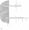
- Fig. 2 shows after the first step the two support legs 2, 3 rammed into the seabed 6.
- the support legs 2, 3 are identical in construction before ramming. Because of the different soil conditions at the different ramming positions or for other reasons, it may be necessary to ram the support legs 2, 3 into the sea floor 6 to different degrees. As a result, their support leg ends 7, 12 on the sea floor protrude differently beyond a sea surface 9. Under sea surface 9, a theoretically smooth sea surface can be seen here at normal zero.
- the first flange 8 of the first support leg 2 and the second flange 11 of the second support leg 3 are arranged at different distances above the sea surface 9, and on the other hand the outermost edges 7a, 12a of the support leg ends are located away from the seabed 7, 12 are arranged at different distances above the sea surface 9.
- the first edge 7a of the first support leg end away from the sea floor and the second edge 12a of the second support leg end 12a away from the sea bottom are each arranged above a desired height after the associated supporting legs 2, 3 have been completely rammed in, and they are adjusted during the second step Fig. 3 cut to the same height above the sea surface 9 at the desired height.
- the different heights of the first and second flanges 8, 11 above the sea surface 9 are compensated for by correspondingly different shortening of pipe sections 13, 14 of a first and a second damping device 16, 17.
- the damping device 16, 17 is a device which is conventionally placed on the upper first edge 7a, 12a of the associated support leg 2, 3, which is remote from the seabed.
- the first damping device 16 has the first tube section 13 on the seabed and a first LMU 18 (Leg Mating Unit), on the end of which is provided a first receptacle 21 for a first support leg stub 24 arranged on an underside of a topside 23.
- the second damping device 17 has the second tube section 14 on the seabed and a second LMU 19, on the end of which is a second receptacle 22 for a second support leg stub 25 arranged on a bottom of the topsides 23.
- the LMUs 18, 19 are built into support structures 30 surrounding them, preferably steel structures.
- the damping devices 16, 17 are mounted on the upper ends of the support legs 2, 3 prior to the lowering of the topsides 23 in order to allow the topsides 23 to be placed on the support legs 2, 3 in a damped manner.
- the pipe sections 13 rest on the edges 7a, 12a of the support legs 2, 3, and the support leg stubs 24, 25 are lowered onto the support structures 30 until they rest on them.
- the conventional damping devices 16, 17 are not placed on the edges 7a, 12a of the support legs 2, 3 at the top, but instead are inserted into the open leg ends 7, 12 of the support legs 2, 3 on the seabed and each on the flange 8 surrounding the inner wall To put on 11. It is provided that the first damping device 16 with its first tube section 13 on the seabed is placed on the first flange 8 surrounding the inner wall and the second damping device 17 with its second pipe section 14 on the seabed is placed on the second flange 11 surrounding the inner wall.
- the pipe sections 13, 14 are shortened in the longitudinal direction L in such a way that the receptacles 21, 22 of the damping devices 16, 17 of the various support legs 2, 3 on the sea floor are at the same distance above the sea surface 9.
- the receptacles 21, 22 are the contact surface of the support leg stubs 24, 25 of the topsides 23.
- Fig. 2 It is shown to what height the two support legs 2, 3 are cut and to what extent the pipe sections 13, 14 of the two damping devices 16, 17 are shortened to different degrees in order to compensate for the different level of the flanges 8, 11 running around the inside wall.
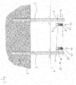
- Fig. 3 shows the first damping device 16, which is inserted into the first support leg end 7, and the insertion of the second damping device 17 into the upper, open second support leg end 12.
- the size of the damping devices 16, 17 is chosen so that that an outer diameter of the tube section 13, 14 is selected to be somewhat smaller than an inner diameter of the associated support leg end 7, 12 and each outer diameter of the damping device 16, 17 is selected to be somewhat smaller than the inner diameter of the associated support leg end 7, 12, so that the damping devices 16, 17 according to Fig. 3 almost completely disappear in the upper support leg ends 7, 12 away from the seabed and only protrude from the first and second support leg ends 7, 12 with a section away from the seabed and the first and second receptacles 21, 22.
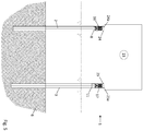
- Fig. 4 the support leg stubs 24, 25 are placed on the two damping devices 16, 17 which are inserted into the two support leg ends 7, 12.
- the topsides 23 can be moved, for example, on a barge that fits between the two support legs 2, 3, so that the topsides 23 on the starboard and port sides protrude beyond the barge.
- the barge is stopped when the support leg stubs 24, 25 are positioned above the associated support legs 2, 3, then the barge is ballasted and the topsides 23 slowly lower with their first support leg stump 24 onto the first receptacle 21 and with their second support leg stump 25 on the second receptacle 22. This position is in Fig. 4 shown.
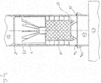
- Fig. 4a shows the topsides 23 according to FIG Fig. 4 shortly before the first support leg stub 24 is placed on the first receptacle 21 of the first damping device 16.
- the first damping device 16 and the first LMU 18 and the first support leg stub 24 are constructed such that a conical projection of the first support leg stub 24 fits into the first receptacle 21 and upon contact with the first receptacle 21, a first stump wall 24a of the support leg stump 24 still has no contact with the upper first edge 7a of the first support leg 2.
- the topsides 23 is further lowered until the topsides 23 is completely set down on the damping devices 16, 17. The barge is then moved out.
- the receptacles 21, 22 are lowered simultaneously and in a coordinated manner, for example by discharging sand from the LMUs 18, 19.
- the LMUs 18, 19 can also store sand stores.
- the recordings 21, 22 gradually sink away from the sea floor as the sand runs off.
- the topsides 23 also sink until the circumferential stump walls 24a, 25a rest on the upper edges 7a, 12a of the respective support leg 2, 3.
- the support legs 24, 25 and the associated support leg 2, 3 are in contact with each other and all support leg stubs 24, 25 are in contact with all support legs 2, 3, the support legs 2, 3 can each along a single circumferential weld 26, 27 with the associated support leg stump 24, 25 are welded.
- Fig. 5a shows the first damping device 16 according to FIG Fig. 4a when the first support leg stub 24 is completely placed on the first receptacle 21, so that the first receptacle 21 is arranged below the upper first edge 7a of the first support leg 2 and the conical projection of the support leg stub 24 has penetrated the open support leg end 7.
Landscapes
- Engineering & Computer Science (AREA)
- General Engineering & Computer Science (AREA)
- Mechanical Engineering (AREA)
- Civil Engineering (AREA)
- Structural Engineering (AREA)
- Foundations (AREA)
Applications Claiming Priority (1)
| Application Number | Priority Date | Filing Date | Title |
|---|---|---|---|
| DE102018133261.0A DE102018133261A1 (de) | 2018-12-20 | 2018-12-20 | Offshore-Plattform mit wenigstens einem Stützbein und ein Verfahren zu ihrer Gründung |
Publications (1)
| Publication Number | Publication Date |
|---|---|
| EP3670752A1 true EP3670752A1 (fr) | 2020-06-24 |
Family
ID=68916186
Family Applications (1)
| Application Number | Title | Priority Date | Filing Date |
|---|---|---|---|
| EP19215700.6A Withdrawn EP3670752A1 (fr) | 2018-12-20 | 2019-12-12 | Plateforme en mer dotée d'au moins une jambe de support et son procédé de création |
Country Status (2)
| Country | Link |
|---|---|
| EP (1) | EP3670752A1 (fr) |
| DE (1) | DE102018133261A1 (fr) |
Cited By (1)
| Publication number | Priority date | Publication date | Assignee | Title |
|---|---|---|---|---|
| EP4621132A1 (fr) | 2024-03-20 | 2025-09-24 | TenneT TSO GmbH | Plate-forme basee sur plusieurs pieux de fondation individuels relies entre eux |
Citations (3)
| Publication number | Priority date | Publication date | Assignee | Title |
|---|---|---|---|---|
| US4662788A (en) * | 1985-02-01 | 1987-05-05 | Conoco Inc. | Offshore platform leg-mating apparatus and a method of assembly |
| US20150240440A1 (en) * | 2012-08-31 | 2015-08-27 | GMC Ltd. | Methods and Connectors for Making Structural Connections Without Offshore Welding of Connectors |
| US20150240439A1 (en) * | 2014-02-23 | 2015-08-27 | China Offshore Oil Engineering Co., Ltd. | Pneumatic Load-Transfer System and Method for Mating an Integrated Deck with a Pre-installed Platform Substructure |
Family Cites Families (1)
| Publication number | Priority date | Publication date | Assignee | Title |
|---|---|---|---|---|
| NL2019110B1 (en) * | 2017-06-22 | 2019-01-07 | Bluemarine Offshore Yard Service Bv | Load absorbing device and method of assembly thereof |
-
2018
- 2018-12-20 DE DE102018133261.0A patent/DE102018133261A1/de not_active Withdrawn
-
2019
- 2019-12-12 EP EP19215700.6A patent/EP3670752A1/fr not_active Withdrawn
Patent Citations (3)
| Publication number | Priority date | Publication date | Assignee | Title |
|---|---|---|---|---|
| US4662788A (en) * | 1985-02-01 | 1987-05-05 | Conoco Inc. | Offshore platform leg-mating apparatus and a method of assembly |
| US20150240440A1 (en) * | 2012-08-31 | 2015-08-27 | GMC Ltd. | Methods and Connectors for Making Structural Connections Without Offshore Welding of Connectors |
| US20150240439A1 (en) * | 2014-02-23 | 2015-08-27 | China Offshore Oil Engineering Co., Ltd. | Pneumatic Load-Transfer System and Method for Mating an Integrated Deck with a Pre-installed Platform Substructure |
Cited By (1)
| Publication number | Priority date | Publication date | Assignee | Title |
|---|---|---|---|---|
| EP4621132A1 (fr) | 2024-03-20 | 2025-09-24 | TenneT TSO GmbH | Plate-forme basee sur plusieurs pieux de fondation individuels relies entre eux |
Also Published As
| Publication number | Publication date |
|---|---|
| DE102018133261A1 (de) | 2020-06-25 |
Similar Documents
| Publication | Publication Date | Title |
|---|---|---|
| EP2877638B1 (fr) | Fondation d'une éoliénne | |
| DE2459478C3 (de) | Verfahren zur Errichtung einer künstlichen Insel | |
| EP2441892B1 (fr) | Dispositif et procédé d'introduction de pieux dans le sol marin | |
| DE1957997A1 (de) | Klammervorrichtung fuer doppelwandige Gehaeuse,die in die Erde eingelassen werden sollen | |
| EP3198083B1 (fr) | Amortisseur de sons émis sous l'eau et procédé de manipulation d'un amortisseur de sons émis sous l'eau | |
| EP2333163B1 (fr) | Structure offshore | |
| DE102007020483A1 (de) | Offshore-Tragstruktur mit konischem Übergangsstück und Zugang in Nähe der Wasserlinie | |
| EP2204497B1 (fr) | Procédé destiné à l'installation d'un agencement offshore flottant et agencement offshore flottant | |
| EP2359997A1 (fr) | Pièce coulée dotée de surfaces planes et parallèles et son dispositif de fabrication | |
| EP3670752A1 (fr) | Plateforme en mer dotée d'au moins une jambe de support et son procédé de création | |
| EP2036815B1 (fr) | Procédé d'installation et de démontage d'une structure de fondation ainsi que structure de fondation et flotteur | |
| EP2036813B1 (fr) | Structure de fondation ainsi que son procédé de fabrication | |
| EP3543459A1 (fr) | Dispositif et procédé de décoffrage d'un tube de tunnel | |
| EP2246502B1 (fr) | Elévateur doté d'une douille de réception adaptable | |
| DE2510656C3 (de) | Verfahren zur Herstellung eines Unterwasserbauwerks aus miteinander durch Verschrauben und Verschweißung verbundenen Teilen und Ausbildung eines StoBes zur Verbindung der Teile | |
| EP3530814B1 (fr) | Procédé de mise en place d'un poste électrique et kit de fondation pour un poste électrique | |
| DE102016116166A1 (de) | Pfahlgründung | |
| DE3443451C1 (de) | Vorrichtung zum Einrichten einer Stütze | |
| DE3106199C2 (de) | Höhenverstellbare Unterstützung für Unterwasserrohrleitungen | |
| DE4219078C2 (de) | Vorrichtung zum Absenken eines Gründungsteils eines Bauwerkes in eine mit Grundwasser gefüllte Baugrube | |
| WO2014096401A2 (fr) | Dispositif et procédé de montage permettant l'installation d'éléments de fixation | |
| DE102010008152A1 (de) | Verfahren zur Herstellung einer Gründungsstruktur für ein Offshore-Bauwerk | |
| DE102012111769A1 (de) | Verfahren zum Herstellen einer Gründungsstruktur | |
| DE1963852A1 (de) | Verfahren zum Errichten eines wenigstens teilweise in einem Gewaesser untergetauchten Bauwerks | |
| EP3412848A2 (fr) | Fosse de montage à double paroi des éléments de paroi |
Legal Events
| Date | Code | Title | Description |
|---|---|---|---|
| PUAI | Public reference made under article 153(3) epc to a published international application that has entered the european phase |
Free format text: ORIGINAL CODE: 0009012 |
|
| STAA | Information on the status of an ep patent application or granted ep patent |
Free format text: STATUS: THE APPLICATION HAS BEEN PUBLISHED |
|
| AK | Designated contracting states |
Kind code of ref document: A1 Designated state(s): AL AT BE BG CH CY CZ DE DK EE ES FI FR GB GR HR HU IE IS IT LI LT LU LV MC MK MT NL NO PL PT RO RS SE SI SK SM TR |
|
| AX | Request for extension of the european patent |
Extension state: BA ME |
|
| STAA | Information on the status of an ep patent application or granted ep patent |
Free format text: STATUS: REQUEST FOR EXAMINATION WAS MADE |
|
| 17P | Request for examination filed |
Effective date: 20201210 |
|
| RBV | Designated contracting states (corrected) |
Designated state(s): AL AT BE BG CH CY CZ DE DK EE ES FI FR GB GR HR HU IE IS IT LI LT LU LV MC MK MT NL NO PL PT RO RS SE SI SK SM TR |
|
| GRAP | Despatch of communication of intention to grant a patent |
Free format text: ORIGINAL CODE: EPIDOSNIGR1 |
|
| STAA | Information on the status of an ep patent application or granted ep patent |
Free format text: STATUS: GRANT OF PATENT IS INTENDED |
|
| RIC1 | Information provided on ipc code assigned before grant |
Ipc: E02D 27/52 20060101ALN20220721BHEP Ipc: E02B 17/00 20060101ALN20220721BHEP Ipc: E02B 17/02 20060101AFI20220721BHEP |
|
| INTG | Intention to grant announced |
Effective date: 20220824 |
|
| STAA | Information on the status of an ep patent application or granted ep patent |
Free format text: STATUS: THE APPLICATION IS DEEMED TO BE WITHDRAWN |
|
| 18D | Application deemed to be withdrawn |
Effective date: 20230104 |