EP3670812B1 - Rauchschutztür-bausatz zum bilden einer rauchschutztür mit verschlusselement zum rauchdichten verschliessen der schliesszylinderaussparung - Google Patents
Rauchschutztür-bausatz zum bilden einer rauchschutztür mit verschlusselement zum rauchdichten verschliessen der schliesszylinderaussparung Download PDFInfo
- Publication number
- EP3670812B1 EP3670812B1 EP19216440.8A EP19216440A EP3670812B1 EP 3670812 B1 EP3670812 B1 EP 3670812B1 EP 19216440 A EP19216440 A EP 19216440A EP 3670812 B1 EP3670812 B1 EP 3670812B1
- Authority
- EP
- European Patent Office
- Prior art keywords
- door leaf
- cover element
- smoke
- base plate
- plate
- Prior art date
- Legal status (The legal status is an assumption and is not a legal conclusion. Google has not performed a legal analysis and makes no representation as to the accuracy of the status listed.)
- Active
Links
Images




Classifications
-
- E—FIXED CONSTRUCTIONS
- E06—DOORS, WINDOWS, SHUTTERS, OR ROLLER BLINDS IN GENERAL; LADDERS
- E06B—FIXED OR MOVABLE CLOSURES FOR OPENINGS IN BUILDINGS, VEHICLES, FENCES OR LIKE ENCLOSURES IN GENERAL, e.g. DOORS, WINDOWS, BLINDS, GATES
- E06B5/00—Doors, windows, or like closures for special purposes; Border constructions therefor
- E06B5/10—Doors, windows, or like closures for special purposes; Border constructions therefor for protection against air-raid or other war-like action; for other protective purposes
- E06B5/16—Fireproof doors or similar closures; Adaptations of fixed constructions therefor
-
- E—FIXED CONSTRUCTIONS
- E05—LOCKS; KEYS; WINDOW OR DOOR FITTINGS; SAFES
- E05B—LOCKS; ACCESSORIES THEREFOR; HANDCUFFS
- E05B15/00—Other details of locks; Parts for engagement by bolts of fastening devices
- E05B15/02—Striking-plates; Keepers; Bolt staples; Escutcheons
-
- E—FIXED CONSTRUCTIONS
- E05—LOCKS; KEYS; WINDOW OR DOOR FITTINGS; SAFES
- E05B—LOCKS; ACCESSORIES THEREFOR; HANDCUFFS
- E05B17/00—Accessories in connection with locks
- E05B17/0075—Insulating, e.g. for limiting heat transfer; Increasing fire-resistance of locks
-
- E—FIXED CONSTRUCTIONS
- E05—LOCKS; KEYS; WINDOW OR DOOR FITTINGS; SAFES
- E05B—LOCKS; ACCESSORIES THEREFOR; HANDCUFFS
- E05B63/00—Locks or fastenings with special structural characteristics
- E05B63/0043—Dummy or simulated locks; Cover elements without lock function
-
- E—FIXED CONSTRUCTIONS
- E06—DOORS, WINDOWS, SHUTTERS, OR ROLLER BLINDS IN GENERAL; LADDERS
- E06B—FIXED OR MOVABLE CLOSURES FOR OPENINGS IN BUILDINGS, VEHICLES, FENCES OR LIKE ENCLOSURES IN GENERAL, e.g. DOORS, WINDOWS, BLINDS, GATES
- E06B3/00—Window sashes, door leaves, or like elements for closing wall or like openings; Layout of fixed or moving closures, e.g. windows in wall or like openings; Features of rigidly-mounted outer frames relating to the mounting of wing frames
- E06B3/70—Door leaves
- E06B2003/7046—Door leaves with provisions for locks, hinges or other fittings
Definitions
- the invention relates to a door leaf for forming a smoke protection door, a method for producing a smoke protection wall closure and a smoke protection wall closure.
- BE 1 013 492 A3 generally discloses a fire door with a mortise lock.
- EN 10 2007 019 883 A1 discloses a decorative plug-in fastener for keyholes.
- the fastener is made of metal or flame-retardant plastic. Smoke-tight properties of the fastener are not known from the document.
- DE 35 30 876 A1 discloses a door lock for fire-retardant doors.
- a pivot plate is hingedly attached to the base plate and is held in the open position by a plastic cover plate. In the event of a fire, the cover plate melts and the pivot plate closes the lock cylinder opening. This should allow a flame arrester to be used even when using a collar lock.
- the document is silent on the smoke sealing properties; neither a door that meets the requirements for a smoke protection door and can therefore be called a smoke protection door, nor a door leaf for such a smoke protection door, nor a smoke-tight door is disclosed.
- Doors are used for building closures in building exterior walls or wall closures in apartment exterior walls or room walls and enable access to and locking of buildings, apartments or rooms.
- doors In addition to the locking function, doors must have other properties depending on the location and purpose of use. These include burglary resistance, sound insulation, thermal insulation, fire protection and smoke protection.
- a smoke protection door is designed to prevent the spread of smoke gases or synonymously smoke in a building in the event of a fire or to limit it sufficiently for as long as possible.
- the door is equipped with a smoke protection device, which can include a door closer, such as an overhead door closer, a surrounding smoke protection seal, a lower door closure in the form of a raised end profile or a lowerable floor seal.
- the locking cylinder inserted into the door leaf also contributes to the smoke-tight closure by closing the recess provided for the locking cylinder in a smoke-tight manner. Doors with a smoke protection function must be marked at the factory and receive a factory certificate.
- the requirements for smoke protection doors are specified in DIN 18095 Part 1. According to this, the leakage rate of a door element when installed and closed must not be greater than 20 m 3 /h for a single-leaf door and not greater than 30 m 3 /h for a double-leaf door.
- the performance characteristics of smoke-tight closure/lock S 200 , smoke-tight closure/lock S a and room closure E are defined in DIN EN 13501-2.
- the requirements to be met for this classification arise from DIN EN 1634-1 and DIN EN 1634-3.
- the smoke protection requirements described here relate to doors installed in a wall opening, i.e. a so-called smoke protection wall closure.
- a door leaf of a smoke protection door in accordance with DIN 18095 with a security locking cylinder as a locking element that closes the locking cylinder opening smoke-tight forms the generic term of claim 1.
- BauPVO Construction products that are placed on the market must comply with the Construction Products Regulation (BauPVO).
- BPR Construction Products Directive
- a declaration of performance must be provided for the construction product when it is delivered, in which the performance of the construction product for its essential characteristics must be specified.
- the declared performance must already be provided by the delivered product.
- a declaration Since the introduction of the CE marking, it is no longer permissible to state that a product is pre-equipped for a specific performance.
- a door that is delivered as a ready-to-install smoke protection door or smoke protection door kit must therefore already contain all the components required for smoke protection.
- the invention provides a door leaf for a smoke protection door which has all the performance characteristics for smoke protection without the need for a locking cylinder and thus meets the requirements for CE marking including a declaration of performance.
- the invention provides a door leaf for a smoke protection wall closure, wherein the door leaf comprises a locking cylinder recess, at least one base plate and a smoke protection device, wherein the smoke protection device has at least one closure element which closes the locking cylinder recess in a smoke-tight manner, wherein the at least one closure element is designed as a flat cover element, wherein the flat cover element covers the locking cylinder recess flatly, is arranged between the door leaf and the base plate in surface contact with the door leaf and the base plate and is pressed against the door leaf by the base plate attached to the door leaf.
- the flat cover element is designed to be arranged between the door leaf and the base plate in flat contact with the door leaf and the base plate.
- the flat cover element has such a cover element hole pattern consisting of one or more cover element holes and/or such a cover element contour that the base plate can be fastened to the door leaf when the flat cover element is arranged between the base plate and the door leaf.
- the flat cover element has such a cover element hole pattern consisting of one or more cover element holes and/or such a cover element contour that the base plate can be fastened to the door leaf through the base plate holes using fastening means, in particular screws.
- the flat cover element has such a cover element hole pattern and/or such a cover element contour that various base plates, in particular the base plates of short plates and/or long plates and/or rosette fittings, can be fastened to the door leaf when the flat cover element is arranged between the base plate and the door leaf.
- the flat cover element has a cover element contour such that, in the mounted state, it is completely covered by the base plate and/or the fitting and/or completely disappears in the base plate and/or the fitting.
- the flat cover element has a cover element contour such that it is formed over its entire surface without cover element holes.
- the flat cover element has a cover element contour such that it is formed over its entire surface without cover element holes.
- the flat cover element has such a thickness that it does not add bulk when arranged between the base plate and the door leaf.
- the flat cover element is a cover plate, in particular a cover plate made of a metal, such as a cover sheet or a cover plate or a cover film made of a polymer material, in particular of a flame-retardant and/or smoke-tight polymer material up to at least 200 °C.
- planar cover element is a flat planar cover element.
- the flat cover element has an adhesive surface for its fastening and/or pre-adjustment on the door leaf surface, in particular in the form of an adhesively bonded cut-out made of double-sided adhesive tape, optionally provided with a pull-off tab, wherein the adhesive bond is detachable, in particular detachable without leaving residue.
- the door leaf comprises several of the above-described closure elements with which the locking cylinder recess can be closed smoke-tight on one or both sides.
- the smoke protection device comprises a circumferential fire protection seal and/or a fire protection handle set and/or a door closer and/or a fire-retardant mineral wool insulation embedded in the door leaf.
- the flat cover element for the door leaf is flat.
- the flat cover element for the door leaf is formed with one or more cover element holes through which the base plate is connected to the door leaf.
- the flat cover element for the door leaf is designed with one or more cover element holes with a cover element hole pattern that enables the attachment of various base plates, such as the base plate of a short plate and/or a long plate and/or a rosette fitting.
- the flat cover element for the door leaf has a cover element contour such that it is formed without cover element holes.
- the flat cover element for the door leaf is designed with a cover element contour such that the cover element is completely covered by the base plate and/or a fitting and/or completely disappears in the base plate and/or in the fitting.
- the flat cover element for the door leaf is designed with such a thickness that it does not protrude between the base plate and the door leaf.
- the flat cover element for the door leaf is designed in the form of a cover plate, in particular a cover plate made of a metal, such as a cover sheet, or a cover plate or a cover film made of a polymer material, in particular of a flame-retardant and/or smoke-tight polymer material up to at least 200 °C.
- the flat cover element for the door leaf has an adhesive surface with which it can be attached or pre-adjusted to the door leaf surface is, in particular in the form of a glued-on cut-out made of double-sided adhesive tape, wherein the bond is detachable, in particular detachable without leaving residue.
- the invention provides a smoke protection wall closure comprising a wall and a smoke protection door in a wall opening, which can be obtained by installing the door leaf according to one of the previously explained embodiments together with a door frame in a wall opening or which can be produced by the previously mentioned method.
- Fig.1 shows a first embodiment of a flat cover element 10 in the form of a large cover plate 12.
- the large cover plate 12 here has, for example, a rectangular cover element contour 18 and a width b of approximately 55 to 95 mm, such as 75 mm, a height h of approximately 70 to 110 mm, such as 90 mm and a thickness d of approximately 0.8 to approximately 1.5 mm, for example 0.5 mm.
- the height, width and cover element contour 18 of the large cover plate 12 can, for example, be selected such that the large cover plate 12 protrudes from one, several or all edges of the fitting after installation on the door leaf 26.
- the cover element hole pattern 14 i.e. the arrangement of the holes in the flat cover element 10, 12 relative to one another.
- the thickness d of the large cover plate 12 must be selected to be large enough to ensure mechanical stability.
- the mechanical stability of the cover plate 12 is necessary for the smoke-tightness of the smoke protection wall closure created during assembly.
- the thickness d of the large cover plate 12 must be small enough that it does not, or does not add much, bulk when the components are screwed together and in a sandwich arrangement between the door leaf 26 and the base plate 56.
- the cover element hole pattern 14 in the flat cover element 10, as shown in Fig.1 The large cover plate 12 shown must be designed and implemented by providing cover element holes 16 so that the locking cylinder recess 20 can be closed smoke-tight by a sufficiently hole-free area in the flat cover element 10 and at the same time the base plate to be attached above the flat cover element 10 during assembly, which has base plate holes for screwing, can be screwed onto the door leaf 26 through cover element holes 16 in the flat cover element 10.
- the large cover plate 12 has, for example, three cover element holes 16, which together form an approximately equilateral triangle standing on a vertex, which here forms the cover element hole pattern 14.
- cover element hole pattern 14 forms the cover element hole pattern 14.
- one or more cover element holes 16 can be used to screw a base plate onto a door leaf 24.
- the dashed line in the shape of an elongated circle in a central position in the large cover plate 12 represents the cylinder cutout 44 in the cover plate 27 of the door leaf 26 for receiving the locking cylinder. In the assembled state, this cutout is closed in a smoke-tight manner by the large cover plate 12, without a locking cylinder or a dummy cylinder having to be inserted into the cutout 27 and recess 20.
- a flat cover element 10 such as a large cover plate 12
- the requirements for CE marking as a smoke protection door can be met without supplying a locking cylinder or dummy cylinder that may not be needed by the customer later.
- a double-sided adhesive tape 22 is also glued to the large cover plate 12. It has a pull-off tab 24 protruding from the left edge and the right edge of the large cover plate 12, with the help of which the protective film on the double-sided adhesive tape 22 can be easily removed.
- Fig.1 further shows an alternative arrangement of the double-sided adhesive tape 22, in which the double-sided adhesive tape 22 with the protruding pull tab 24 is arranged rotated by 90 °.
- the double-sided adhesive tape 22 is an optional feature of the flat cover element 10, such as the large cover plate 12. It serves as an assembly aid and should advantageously be able to be removed without leaving any residue.
- the large cover plate 12 can be fixed precisely to the surface of the door leaf 26 before the base plate 56 is screwed onto the large cover plate 12 and the door leaf 26 to form a sandwich structure. By screwing it on, the large cover plate 12 is pressed by the base plate against the surface of the door leaf 26.
- the smoke-tight seal which must withstand a smoke gas temperature of up to 200 °C at a load pressure of up to 50 Pa after 30 minutes, is essentially achieved by this pressing of the large cover plate 12, but can be further reinforced by the adhesive connection between the large cover plate 12 and the door leaf 26.
- the adhesive tape itself can also form the flat covering element 10 if the backbone material used for the adhesive tape consists of a permanently smoke-tight or smoke-gas-tight polymer material.
- Fig.1 Below the front view of the large cover plate 12 is a perspective view of the large cover plate 12.
- the large cover plate 12 can be included in the handle package.
- the customer or the fitter can decide whether to install an existing profile cylinder or to seal the locking cylinder recess 20 with the large cover plate 12 to make it smoke-tight. If the profile cylinder is only installed after the fitting has been installed for the first time using the large cover plate 12, the handle base plate is first dismantled, then the large cover plate 12 attached with double-sided adhesive tape 22 is removed, the locking cylinder, for example a profile cylinder, is inserted and then the handle base plate is reinstalled.
- Fig.2 the possible cover plate millings in the cover plate 27 of a door leaf 26 are shown, which is made up of a cover plate 27, a box plate (not visible) and a filling (not visible).
- the handle set 28 can comprise a rosette fitting 38, 40 or a short plate 32.
- the cover plate 27 has either a rosette fitting milling 46 or a short plate milling 48 in addition to the cylinder milling 44.
- the millings in the cover plate 27 consist of a cylinder milling 44 and a short plate milling 48 under the cylinder milling 44. If the handle set includes a rosette fitting with cylinder rosette 40, the millings in the cover plate 27 consist of a cylinder milling 44 and two rosette fitting millings 46 to the left and right of the cylinder milling.
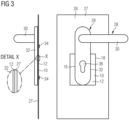
- Fig.3 shows the front view of a door leaf 26 or the cover plate 27 of the door leaf 26 in the area of the mounted handle set 28, which here includes a short plate 32.
- the latch 30, the short plate 32 and the cylinder hole 36 in the short plate 32 are visible here. Not visible are the base plate 56 and the cylinder cutout 44 and the short plate cutout 48 in the cover plate 27, which are covered by the large cover plate 12 and the short plate 32.
- the handle base plate 56 arranged under the short plate 32 is screwed to the cover plate 27 of the door leaf 26 with two screws 34 through two base plate holes 58 in the base plate 56.
- the large cover plate 12 is fixed in a sandwich structure between the screwed base plate 56 and the door leaf 26.
- the screwed base plate 56 presses the large cover plate 12 against the door leaf 26 or the cover plate 27 and ensures the smoke-tight closure of the cylinder cutout 44 and the locking cylinder recess 20.
- the large cover plate 12 corresponds to the Fig.1 shown large cover plate 12 and has three cover element holes 16 with the Fig.1 shown cover element hole pattern 14.
- the large cover plate 12 provided with double-sided adhesive tape 22 is glued to the cover plate 27 of the door leaf 26 in such a way that its central area covers the cylinder cutout 44 and the locking cylinder recess 20 and the lower cover element hole 16 is arranged symmetrically in the middle on a vertical center line of the locking cylinder recess 20.
- the base plate 56 is then fixed to the cover plate 27 of the door leaf 26 using two screws 34.
- the lower screw 34 is guided through the lower base plate hole 58 and through the lower cover element hole 16 in the large cover plate 12.
- the large cover plate 12 is firmly fixed between the base plate 56 and the door leaf 26, thus sealing the locking cylinder recess 20 in the door leaf 26 in a smoke-tight manner.
- the two upper locking element holes 14 remain inoperative when the short plate 32 is used and protrude to the left when the handle set 28 is fully assembled. and partially protrudes to the right of the short plate 30. Likewise, the large cover plate 12 protrudes clearly as a rectangle to the left and right under the fitting.
- This arrangement of handle 30, short plate 32, screws 34 on door leaf 26 or cover plate 27 of door leaf 26 is illustrated in the side view to the left of the front view.
- An enlarged detail at X shows in detail the sandwich structure of short plate 32 (underneath which the base plate 56 is hidden), large cover plate 12 with a thickness d of, for example, 0.5 mm and cover plate 27.
- FIG.4 Another embodiment of a smoke protection door is shown after installation of the smoke protection door kit.
- the difference to the Fig.3 The embodiment shown consists in that, instead of the short plate 32, a rosette fitting consisting of a latch rosette 38 and a cylinder rosette 40 is used and correspondingly shaped base plates 56 are used under the two rosettes 38, 40.
- the base plate 56 of the cylinder rosette 40 has two screw holes (not visible) to the left and right of the cylinder hole 36 in the cylinder rosette 40, through which the base plate 56 is screwed to the cover plate 27.
- the base plate 56 of the rosette fitting for screwing has a different hole pattern than the base plate 56 of the short plate 32, the same large cover plate 12 as in the embodiment of Fig.3 Instead of the lower cover element hole 16, the two upper cover element holes 16 are now used for screwing on the base plate 56 (see Fig.1 ). In this embodiment, the lower of the three cover element holes 16 remains inoperative and protrudes below the cylinder rosette 40.
- the hole pattern of the base plates 56 differs considerably in a fitting with a short plate 32 and a rosette fitting 38, 40, the same flat cover element 10 or large cover plate 12 can be used to produce the smoke-tight closure of the locking cylinder recess 20, because the flat cover element 10 has a cover element hole pattern 14 that is compatible with both basic plate hole patterns.
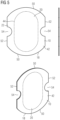
- Fig.5 shows a second embodiment of a flat cover element 10 in the form of a small cover plate 42.
- the small cover plate 12 has, as a cover element contour 18, two opposing curved edges in the form of circular arcs 50 of equal size, which are connected to one another by two predominantly parallel and overall mirror-image straight edges 52.
- Semicircular cover element recesses 54 are provided in the middle of the parallel straight edges.
- the drawing of the small cover plate 42 has a dashed line in the shape of an elongated circle in the central position. This area corresponds to the cylinder cutout 44 which is formed in the cover plate of the door leaf 26 to accommodate the locking cylinder and which, when installed, is closed off smoke-tight by the small cover plate 42.
- the base plate 56 and the small cover plate 42 By screwing the base plate 56 and the small cover plate 42 over the cover plate cylinder cutout 44, the locking cylinder recess 20 in the door leaf 26 is closed off smoke-tight without a locking cylinder or a dummy cylinder having to be inserted into the recess.
- the double-sided adhesive tape 22 is formed here without any protruding release film.
- Fig.5 Below the front view of the small cover plate 42 is a perspective view of the small cover plate 42.
- Fig.6 illustrates the use of the small cover plate 42 according to Fig.5 for a smoke protection door with short plate handle set.
- the use of the small cover plate 42 is the only and essential difference to the Fig.3 All other components and reference symbols correspond to Fig.3 so that in this respect Fig.3 can be referred to.
- the upper illustration shows the front view and the side view of the door leaf in the area of the handle, the lower illustration shows a rear view of the door leaf in the area of the handle without the box sheet that is actually present.
- the small cover plate 42 has such dimensions that it is completely covered by the short plate 32. This gives an aesthetic overall impression while maintaining a good smoke-tight closure of the cylinder cutout 44 and the locking cylinder recess 20.
- the rear view of the door leaf 26 illustrates the precise arrangement of the small cover plate 42 between the base plate 56 and the door leaf 26.
- the small cover plate 42 can be fitted with its parallel vertical edges exactly into the short plate 32 with its vertical parallel edges. It lies flat on the base plate 56. Due to the arrangement of the two base plate holes 58 in the base plate 52 below and above the small cover plate 42, the cover element recesses 54 in the small cover plate 42 are inoperative. Due to the sufficiently large distance between the base plate holes 58 in the base plate 52 and the cylinder hole 36 in the base plate 52 and at the same time the sufficiently small dimensions of the small cover plate 42, the screwing of the base plate 56 to the door leaf 26 is not hindered by the small cover plate 42. Thus, no further cover element holes 16 need to be provided in the small cover plate 42, as in the embodiment according to Fig.1 and Fig.3 are required.
- the side view of the embodiment according to Fig.6 shows that the small cover plate 42 has such dimensions that it fits completely in the recess of the Short shield 32 disappears. Unlike in Fig.3 The small cover plate 42 does not add any bulk at all.
- the small cover plate 42 For the installation of the small cover plate 42, it is advantageous to provide the small cover plate with a double-sided adhesive tape 22 without a pull-off tab. After removing the protective film of the double-sided adhesive tape 22, the small cover plate 42 is glued either over the cylinder cutout 44 onto the door leaf 26 or onto the base plate 56.
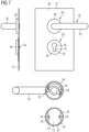
- Fig.7 illustrates the use of the small cover plate 42 according to Fig.5 for a smoke protection door with rosette fitting.
- the use of the small cover plate 42 instead of the large cover plate 12 is the only and essential difference to the Fig.4 Since all other components and reference numerals are Fig.4 can be referred to the description of the embodiment according to Fig.4 can be referred to.
- the upper illustration in Fig.7 shows the front view and the side view of the door leaf 26 in the area of the handle.
- the lower illustration shows a rear view of the door leaf 26 in the area of the handle without the box sheet that is actually present.
- FIG.7 shows that the small cover plate 42 has such dimensions that it is completely covered by the cylinder rosette 40. This gives an overall aesthetic impression while maintaining a good smoke-tight closure of the cylinder cutout 44 and the locking cylinder recess 20.
- the rear view of the door leaf 26 illustrates the precise arrangement of the small cover plate 42 between the base plate 56 of the cylinder rosette 40 and the door leaf 26.
- the small cover plate 42 with its basic shape derived from a circle, fits exactly into the recess of the circular and slightly larger cylinder rosette 40. It lies flat on the circular base plate 56.
- the two base plate holes 58 are arranged in the base plate 56 to the left and right of the invisible cylinder hole 36.
- the recesses 54 in the small cover plate 42 enable the base plate 56 to be screwed to the door leaf 26 without hindrance.
- Cover element holes 16 are not required due to the cover element contour 18. This represents a significant difference to the embodiment according to Fig.1 and Fig.4 in which the large cover plate 12 has a cover element hole pattern 14 which enables the base plate to be screwed to the door leaf 26.
- the side view of the embodiment according to Fig.7 shows that the small cover plate 42 has such dimensions that it completely disappears in the recess of the cylinder rosette 40. Unlike in Fig.5 the small cover plate 42 does not add any bulk at all.
- the hole pattern of the base plates 56 and their contour differ considerably in a short plate 32 and a rosette fitting consisting of a handle rosette 38 and a cylinder rosette 40, the same small cover plate 42 can be used to create the smoke-tight closure of the locking cylinder recess 20 during the initial assembly of the smoke protection door using the smoke protection door kit, because the small cover plate 42 has the cover element contour 18 required for this.
- cover element contour 18 By further refining the cover element contour 18 and, if necessary, providing a more universal hole pattern in the flat cover element 10, it is possible to also cover the handle hole pattern of other handle sets, such as H8-5. With appropriate design, many different smoke protection door assemblies with different handle sets and different handle hole patterns can be equipped with a single flat cover element 10.
Landscapes
- Engineering & Computer Science (AREA)
- Structural Engineering (AREA)
- Physics & Mathematics (AREA)
- Thermal Sciences (AREA)
- Civil Engineering (AREA)
- Special Wing (AREA)
- Specific Sealing Or Ventilating Devices For Doors And Windows (AREA)
- Casings For Electric Apparatus (AREA)
Description
- Die Erfindung betrifft ein Türblatt zum Bilden einer Rauchschutztür, ein Verfahren zum Herstellen eines Rauchschutzwandabschlusses sowie einen Rauchschutzwandabschluss.
-
BE 1 013 492 A3 -
DE 10 2007 019 883 A1 offenbart einen Zier-Steckverschluss für Schlüssellöcher. Der Verschluss ist aus Metall oder schwerentflammbarem Kunststoff hergestellt. Rauchdichtungseigenschaften des Verschlusses sind aus dem Dokument nicht bekannt. -
DE 35 30 876 A1 offenbart ein Türschloss für feuerhemmende Türen. Eine Schwenkplatte ist gelenkig an dem Grundschild befestigt und wird durch ein Überdeckschild aus Kunststoff in offener Position gehalten. Bei einem Brand schmilzt der Überdeckschild und die Schwenkplatte verschließt die Schließzylinderöffnung. Dadurch soll ein Flammendurchschlag auch bei Verwendung eines Bundbartschlosses verwendbar sein. Zu den Rauchdichtungseigenschaften schweigt das Dokument; es ist weder eine Tür, die die Anforderungen an eine Rauchschutztür erfüllt und somit als Rauchschutztür bezeichnet werden darf, noch ein Türblatt für eine solche Rauchschutztür noch eine rauchdichte Tür offenbart. - Türen werden für Gebäudeabschlüsse in Gebäudeaußenwänden oder Wandabschlüsse in Wohnungsaußenwänden oder Raumwänden verwendet und ermöglichen das Begehen und Verschließen der Gebäude, Wohnungen oder Räume. Neben der Schließfunktion müssen Türen je nach Einsatzort und Einsatzzweck weitere Eigenschaften aufweisen. Hierzu gehören Einbruchhemmung, Schalldämmung, Wärmedämmung, Feuerschutz und Rauchschutz.
- Eine Rauchschutztür ist dafür ausgebildet, bei einem Brand das Ausbreiten von Rauchgasen oder synonym Rauch in einem Gebäude zu verhindern oder möglichst lange hinreichend einzuschränken. Hierfür wird die Tür mit einer Rauchschutzeinrichtung ausgerüstet, die einem Türschließer, wie Obentürschließer, eine umlaufende Rauchgasschutzdichtung, einen unteren Türabschluss in Form eines erhöhten Abschlussprofils oder einer absenkbaren Bodendichtung, umfassen kann. Zum rauchdichten Verschluss trägt auch der in das Türblatt eingesetzte Schließzylinder bei, indem er die für den Schließzylinder vorgesehene Aussparung rauchdicht verschließt. Türen mit Rauchschutzfunktion müssen werkseitig gekennzeichnet werden und erhalten eine Werksbescheinigung.
- Die Anforderungen an Rauchschutztüren sind in der DIN 18095 Teil 1 festgelegt. Danach darf die Leckrate eines Türelements im eingebauten und geschlossenen Zustand nicht größer als 20 m3/h bei einer einflügeligen Tür und nicht größer als 30 m3/h bei einer zweiflügligen Tür sein. Die Leistungseigenschaften rauchdichter Abschluss/Verschluss S200, rauchdichter Abschluss/Verschluss Sa und Raumabschluss E sind in DIN EN 13501-2 definiert. Die für diese Klassifizierung zu erfüllenden Voraussetzungen ergeben sich aus DIN EN 1634-1 und DIN EN 1634-3. Die hier beschriebenen Anforderungen an den Rauchschutz betreffen die in eine Wandöffnung eingebauten Türen, also einen sogenannten Rauchschutzwandabschluss. Ein Türblatt einer Rauchschutztür gemäß DIN 18095 mit Sicherheitsschließzylinder als Verschlusselement, das die Schließzylinderöffnung rauchdicht verschließt, bildet den Oberbegriff des Anspruchs 1.
- Bauprodukte, die in den Verkehr gebracht werden, müssen der Bauprodukte-Verordnung BauPVO entsprechen. Die BauPVO unterscheidet sich durch die Leistungserklärung und die CE-Kennzeichnung von der früheren Bauprodukte-Richtlinie BPR. Damit ein Bauprodukt mit einer CE-Kennzeichnung in den Verkehr gebracht werden darf, muss für das Bauprodukt bei seiner Auslieferung eine Leistungserklärung mitgegeben werden, in der die Leistungen des Bauprodukts für dessen wesentliche Merkmale anzugeben sind. Die erklärten Leistungen müssen dabei bereits von dem ausgelieferten Produkt erbracht werden. Eine Erklärung, dass ein Produkt für eine bestimmte Leistung vorgerüstet ist, ist also seit Einführung der CE-Kennzeichnung nicht mehr zulässig.
- Eine Tür, die als einbaufertige Rauchschutztür oder Rauchschutztür-Bausatz ausgeliefert wird, muss also bereits alle Komponenten umfassen, die für den Rauchschutz erforderlich sind.
- Die Voraussetzungen für die CE-Kennzeichnung eines Rauchschutztür-Bausatzes können derzeit nur erfüllt werden, wenn ein Schließzylinder zum Lieferumfang gehört. Ohne Auslieferung eines Schließzylinders würde der Rauchschutztür-Bausatz kein Bauteil aufweisen, das das Hindurchtreten von Rauchgas durch die Schließzylinderaussparung verhindern könnte. Das Beifügen eines Schließzylinders ist aber kostspielig. Außerdem ist das Beifügen eines Schließzylinders obsolet, wenn der Endverbraucher anschließend die Tür in einer Schließanlage nutzen möchte.
- Es ist Aufgabe der vorliegenden Erfindung, ein weniger kostspieliges Türblatt für eine Rauchschutztür bereitzustellen.
- Die Aufgabe wird durch den Gegenstand der unabhängigen Ansprüche gelöst. Bevorzugte Weiterbildungen sind Gegenstand der abhängigen Ansprüche.
- Mit der Erfindung wird ein Türblatt für eine Rauchschutztür bereitgestellt, das ohne das Mitliefern eines Schließzylinders alle Leistungsmerkmale für einen Rauchschutz aufweist und somit die Voraussetzungen für eine CE-Kennzeichnung samt Leistungserklärung erfüllt.
- Gemäß einem Aspekt schafft die Erfindung ein Türblatt für einen Rauchschutzwandabschluss, wobei das Türblatt eine Schließzylinderaussparung, mindestens einen Grundschild und eine Rauchschutzeinrichtung umfasst, wobei die Rauchschutzeinrichtung wenigstens ein Verschlusselement aufweist, das die Schließzylinderaussparung rauchdicht verschließt, wobei das wenigstens eine Verschlusselement als flächiges Abdeckelement ausgebildet ist, wobei das flächige Abdeckelement die Schließzylinderaussparung flächig abdeckt, zwischen dem Türblatt und dem Grundschild jeweils im flächigen Kontakt mit dem Türblatt und dem Grundschild angeordnet ist und von dem am Türblatt befestigten Grundschild gegen das Türblatt gepresst wird.
- Es ist bevorzugt, das flächige Abdeckelement dafür ausgebildet ist, zwischen dem Türblatt und dem Grundschild im flächigen Kontakt mit Türblatt und Grundschild angeordnet zu werden.
- Es ist bevorzugt, dass das flächige Abdeckelement ein solches Abdeckelement-Lochbild aus einem oder mehreren Abdeckelementlöchern und/oder eine solche Abdeckelement-Kontur aufweisen, dass der Grundschild bei zwischen dem Grundschild und dem Türblatt angeordnetem flächigen Abdeckelement an dem Türblatt befestigt werden kann.
- Es ist bevorzugt, dass das flächige Abdeckelement ein solches Abdeckelement-Lochbild aus einem oder mehreren Abdeckelementlöchern und/oder eine solche Abdeckelement-Kontur aufweist, dass der Grundschild durch die Grundschildbohrungen hindurch mit Befestigungsmitteln, insbesondere Schrauben, an dem Türblatt befestigt werden kann.
- Es ist bevorzugt, dass das flächige Abdeckelement ein solches Abdeckelement-Lochbild und/oder eine solche Abdeckelement-Kontur aufweist, dass verschiedene Grundschilde, insbesondere die Grundschilde von Kurzschilden und/oder Langschilden und/oder Rosettenbeschlägen, bei zwischen dem Grundschild und dem Türblatt angeordnetem flächigen Abdeckelement an dem Türblatt befestigt werden können.
- Es ist bevorzugt, dass das flächige Abdeckelement eine solche Abdeckelement-Kontur aufweist, dass es im montierten Zustand vollständig von dem Grundschild und/oder dem Beschlag verdeckt wird und/oder vollständig im Grundschild und/oder im Beschlag verschwindet.
- Es ist bevorzugt, dass das flächige Abdeckelement eine solche Abdeckelement-Kontur aufweist, dass es vollflächig ohne Abdeckelementlöcher ausgebildet ist.
- Es ist bevorzugt, dass das flächige Abdeckelement eine solche Abdeckelement-Kontur aufweist, dass es vollflächig ohne Abdeckelementlöcher ausgebildet ist.
- Es ist bevorzugt, dass das flächige Abdeckelement eine solche Dicke hat, dass es bei Anordnung zwischen Grundschild und Türblatt nicht aufträgt.
- Es ist bevorzugt, dass das flächige Abdeckelement eine Abdeckplatte, insbesondere eine Abdeckplatte aus einem Metall, wie ein Abdeckblech oder eine Abdeckplatte oder eine Abdeckfolie aus einem Polymermaterial, insbesondere aus einem flammhemmend ausgerüsteten und/oder bis mindestens 200 °C rauchdichten Polymermaterial, ist.
- Es ist bevorzugt, dass das flächige Abdeckelement ein ebenes flächiges Abdeckelement ist.
- Es ist bevorzugt, dass das flächige Abdeckelement eine klebfähige Oberfläche für seine Befestigung und/oder Vorjustierung auf der Türblattoberfläche aufweist, insbesondere in Form eines aufgeklebten, gegebenenfalls mit einer Abziehlasche versehenen Zuschnitts aus doppelseitigem Klebeband, wobei die Klebung lösbar, insbesondere rückstandsfrei lösbar ist.
- Es ist bevorzugt, dass das Türblatt mehrere der oben beschriebenen Verschlusselemente umfasst, mit denen die Schließzylinderaussparung einseitig oder beidseitig rauchdicht verschlossen werden kann.
- Es ist bevorzugt, dass die Rauchschutzeinrichtung eine umlaufende Feuerschutzdichtung und/oder eine Feuerschutz-Drückergarnitur und/oder einen Türschließer und/oder eine in das Türblatt eingelassene feuerhemmende Mineralwolldämmung umfasst.
- Es ist bevorzugt, dass das flächige Abdeckelement für das Türblatt eben ausgebildet ist.
- Es ist bevorzugt, dass das flächige Abdeckelement für das Türblatt mit einem oder mehreren Abdeckelementlöchern ausgebildet ist, durch die hindurch der Grundschild mit dem Türblatt verbunden ist.
- Es ist bevorzugt, dass das flächige Abdeckelement für das Türblatt jeweils mit einem oder mehreren Abdeckelementlöchern mit einem Abdeckelementlochbild ausgebildet ist, das die Befestigung verschiedener Grundschilde, wie des Grundschilds eines Kurzschilds und/oder eines Langschilds und/oder eines Rosettenbeschlags, ermöglicht.
- Es ist bevorzugt, dass das flächige Abdeckelement für das Türblatt eine solche Abdeckelementkontur aufweist, dass es ohne Abdeckelementlöcher ausgebildet sind.
- Es ist bevorzugt, dass das flächige Abdeckelement für das Türblatt mit einer solchen Abdeckelementkontur ausgebildet ist, dass das Abdeckelement vollständig von dem Grundschild und/oder einem Beschlag verdeckt ist und/oder vollständig im Grundschild und/oder im Beschlag verschwinden.
- Es ist bevorzugt, dass das flächige Abdeckelement für das Türblatt mit einer solchen Dicke ausgebildet ist, dass es zwischen dem Grundschild und dem Türblatt nicht aufträgt.
- Es ist bevorzugt, dass das flächige Abdeckelement für das Türblatt in Form einer Abdeckplatte, insbesondere einer Abdeckplatte aus einem Metall, wie ein Abdeckblech, oder einer Abdeckplatte oder einer Abdeckfolie aus einem Polymermaterial, insbesondere aus einem flammhemmend ausgerüsteten und/oder bis mindestens 200 °C rauchdichten Polymermaterial, ausgebildet ist.
- Es ist bevorzugt, dass das flächige Abdeckelement für das Türblatt eine klebfähige Oberfläche aufweist, mit der es auf der Türblattoberfläche befestigt oder vorjustiert ist, insbesondere in Form eines aufgeklebten Zuschnitts aus doppelseitigem Klebeband, wobei die Klebung lösbar, insbesondere rückstandsfrei lösbar ist.
- Die Erfindung schafft weiterhin ein Verfahren zum Herstellen eines Rauchschutzwandabschlusses unter Verwendung des Türblatts gemäß einer der zuvor erläuterten Ausgestatlungen, das mindestens die folgenden Schritte umfasst:
- Befestigen einer Türzarge in einer Wandöffnung und
- Verbinden des Türblatts mit der Türzarge.
- Gemäß einem Aspekt schafft die Erfindung einen Rauchschutzwandabschluss aus einer Wand und einer Rauchschutztür in einer Wandöffnung, der durch Einbau des Türblatts gemäß einer der zuvor erläuterten Ausgestaltungen zusammen mit einer Türzarge in eine Wandöffnung erhältlich ist oder der durch das zuvor erwähnte Verfahren herstellbar ist.
- Im Folgenden werden Ausführungsbeispiele anhand der beigefügten Zeichnungen näher erläutert. Darin zeigt:
- Fig. 1
- die Vorderansicht einer ersten Ausführungsform eines flächigen Abdeckelements in Form eines großen Abdeckblechs und darunter eine perspektivische Ansicht des großen Abdeckblechs;
- Fig. 2
- Deckblechfräsungen im Deckblech eines Rauchschutztür-Türblatts für eine Drückergarnitur mit Kurzschild und eine Drückergarnitur mit Rosettenbeschlag
- Fig. 3
- die Vorderansicht eines Türblatts im Bereich des Türdrückers mit Kurzschild als Beschlag und dem großen Abdeckblech gemäß
Fig. 1 als flächiges Abdeckelement, eine Seitenansicht des Bereichs und eine Ausschnittvergrößerung der Seitenansicht; - Fig. 4
- die Vorderansicht eines Türblatts im Bereich des Türdrückers mit Rosettenbeschlag und dem großen Abdeckblech gemäß
Fig. 1 als flächiges Abdeckelement, eine Seitenansicht des Teilbereichs und eine Ausschnittvergrößerung der Seitenansicht; - Fig. 5
- die Vorderansicht einer zweiten Ausführungsform eines flächigen Abdeckelements in Form eines kleinen Abdeckblechs und darunter eine perspektivische Ansicht des kleinen Abdeckblechs;
- Fig. 6
- die Vorderansicht eines Türblatts im Bereich des Türdrückers mit Kurzschild als Beschlag und dem kleinen Abdeckblech gemäß
Fig. 5 als flächiges Abdeckelement, eine Seitenansicht des Bereichs und eine Rückansicht des Türdrückers mit kleinem Abdeckblech ohne Kastenblech; - Fig. 7
- die Vorderansicht eines Türblatts im Bereich des Türdrückers mit Rosettenbeschlag und dem kleinen Abdeckblech gemäß
Fig. 5 als flächiges Abdeckelement, eine Seitenansicht des Bereichs und eine Rückansicht des Türdrückers mit kleinem Abdeckblech ohne Kastenblech. -
Fig. 1 zeigt eine erste Ausführungsform eines flächigen Abdeckelements 10 in Form eines großen Abdeckblechs 12. - Das große Abdeckblech 12 hat hier beispielsweise eine rechteckige Abdeckelement-Kontur 18 und eine Breite b von etwa 55 bis 95 mm, wie 75 mm, eine Höhe h von etwa 70 bis 110 mm, wie 90 mm und eine Dicke d von etwa 0,8 bis etwa 1,5 mm, beispielsweise 0,5 mm. Höhe, Breite und Abdeckelement-Kontur 18 des gro-βen Abdeckblechs 12 können beispielsweise so gewählt werden, dass das große Abdeckblech 12 nach der Montage auf dem Türblatt 26 einem, mehreren oder allen Rändern des Beschlags hervorragt.
- Wichtig für die Verwendung und die Montage des großen Abdeckblechs 12 sind seine Dicke d und das Abdeckelement-Lochbild 14, also die Anordnung der Löcher im flächigen Abdeckelement 10, 12 zueinander.
- Die Dicke d des großen Abdeckblechs 12 muss so groß gewählt werden, dass die mechanische Stabilität gewährleistet ist. Die mechanische Stabilität des Abdeckblechs 12 ist für die Rauchdichtigkeit des bei der Montage entstehenden Rauchschutzwandabschlusses erforderlich. Andererseits muss die Dicke d des großen Abdeckblechs 12 so gering sein, dass es beim Verschrauben der Bauteile und in Sandwich-Anordnung zwischen dem Türblatt 26 und dem Grundschild 56 nicht oder nicht sehr aufträgt.
- Das Abdeckelement-Lochbild 14 im flächigen Abdeckelement 10, wie dem in
Fig. 1 dargestellten großen Abdeckblech 12, muss so konzipiert und durch Vorsehen von Abdeckelementlöchern 16 realisiert werden, dass die Schließzylinderaussparung 20 durch einen hinreichend lochfreien Bereich im flächigen Abdeckelement 10 rauchdicht verschlossen werden kann und gleichzeitig der bei der Montage über dem flächigen Abdeckelement 10 anzubringende Grundschild, der Grundschildbohrungen für das Anschrauben aufweist, durch Abdeckelementlöcher 16 im flächigen Abdeckelement 10 hindurch auf dem Türblatt 26 festgeschraubt werden kann. - Das große Abdeckblech 12 weist beispielhaft drei Abdeckelementlöcher 16 auf, die miteinander in etwa ein gleichseitiges, auf einer Spitze stehendes Dreieck aufspannen, das hier das Abdeckelement-Lochbild 14 bildet. Für das Anschrauben eines Grundschilds an ein Türblatt 24 können je nach Grundschilds-Lochbild bzw. Drückerlochbild ein oder mehrere Abdeckelementlöcher 16 verwendet werden.
- Die gestrichelte Linie mit der Form eines gestreckten Kreises in zentraler Position im großen Abdeckblech 12 stellt die Zylinderausfräsung 44 im Deckblech 27 des Türblatts 26 für die Aufnahme des Schließzylinders dar. Diese Ausfräsung wird montierten Zustand durch das große Abdeckblech 12 rauchdicht verschlossen, ohne dass ein Schließzylinder oder ein Blindzylinder in Ausfräsung 27 und Aussparung 20 eingesetzt werden muss.
- Somit können durch Mitliefern eines flächigen Abdeckelements 10, wie eines gro-βen Abdeckblechs 12, die Voraussetzungen für die CE-Kennzeichnung als Rauchschutztür erfüllt werden, ohne dass ein Schließzylinder oder Blindzylinder ausgeliefert wird, der später vom Kunden gegebenenfalls nicht gebraucht wird.
- Auf das große Abdeckblech 12 ist weiterhin ein doppelseitiges Klebeband 22 aufgeklebt. Es weist eine am linken Rand und am rechten Rand des großen Abdeckblechs 12 überstehende Abziehlasche 24 auf, mit deren Hilfe die Schutzfolie auf dem doppelseitigen Klebeband 22 leicht entfernt werden kann.
Fig. 1 zeigt weiterhin eine alternative Anordnung des doppelseitigen Klebeband 22, bei der das doppelseitige Klebeband 22 mit überstehender Abziehlasche 24 um 90 ° gedreht angeordnet ist. - Das doppelseitige Klebeband 22 stellt ein fakultatives Merkmal des flächigen Abdeckelements 10, wie des großen Abdeckblechs 12, dar. Es dient als Montagehilfe und sollte sich vorteilhaft rückstandslos abziehen lassen. Mit ihm kann das große Abdeckblech 12 passgenau auf der Oberfläche des Türblatts 26 fixiert werden, bevor der Grundschild 56 auf das große Abdeckblech 12 und das Türblatt 26 unter Bildung einer Sandwich-Struktur aufgeschraubt wird. Durch das Anschrauben wird das große Abdeckblech 12 von dem Grundschild gegen die Oberfläche des Türblatts 26 gepresst. Die rauchdichte Abdichtung, die einer Rauchgastemperatur bis zu 200 °C bei einem Belastungsdruck bis zu 50 Pa nach 30 min widerstehen muss, erfolgt im Wesentlichen durch dieses Anpressen des großen Abdeckblechs 12, kann aber durch die klebende Verbindung zwischen großem Abdeckblech 12 und Türblatt 26 weiter verstärkt werden.
- Bei Verwendung eines doppelseitigen oder einseitigen Klebebands kann das Klebeband aber auch selbst das flächige Abdeckelement 10 bilden, wenn die das für das Klebeband verwendete Rückgratmaterial aus einem dauerhaft rauchdichten oder rauchgasdichten Polymermaterial besteht.
- Zur Veranschaulichung der Größenverhältnisse zeigt
Fig. 1 unterhalb der Vorderansicht des großen Abdeckblechs 12 eine perspektivische Ansicht des großen Abdeckblechs 12. - Das große Abdeckblech 12 kann dem Drückerpaket beigefügt werden. Bei der Montage des Drückers kann der Kunde oder der Monteur entscheiden, ob er einen bereits vorhandenen Profilzylinder einbaut oder ob er die Schließzylinderaussparung 20 mit dem großen Abdeckblech 12 rauchdicht verschließt. Wenn der Profilzylinder erst nach der Erstmontage des Beschlags unter Verwendung des gro-βen Abdeckblechs 12 eingesetzt wird, wird zunächst der Drückergrundschild demontiert, dann das mit doppelseitigem Klebeband 22 befestigte große Abdeckblech 12 entfernt, der Schließzylinder, beispielsweise Profilzylinder, eingesetzt und dann der Drückergrundschild wieder montiert.
- In
Fig. 2 werden die möglichen Deckblechfräsungen im Deckblech 27 eines Türblatts 26 gezeigt, das aus einem Deckblech 27, einem Kastenblech (nicht sichtbar) und einer Füllung (nicht sichtbar) aufgebaut ist. Für die Montage der Drückergarnitur 28 auf dem Türblatt 26 müssen im Deckblech 27 und im Kastenblech Fräsungen vorgesehen sein. Die Drückergarnitur 28 kann einen Rosettenbeschlag 38, 40 oder einen Kurzschild 32 umfassen. Je nach Beschlag weist das Deckblech 27 neben der Zylinderausfräsung 44 entweder eine Rosettenbeschlagausfräsung 46 oder eine Kurzschildausfräsung 48 auf. - Wenn die Drückergarnitur einen Kurzschild 32 umfasst, bestehen die Fräsungen im Deckblech 27 aus einer Zylinderausfräsung 44 und einer Kurzschildausfräsung 48 unter der Zylinderausfräsung 44. Wenn die Drückergarnitur einen Rosettenbeschlag mit Zylinderrosette 40 umfasst, bestehen die Fräsungen im Deckblech 27 aus einer Zylinderausfräsung 44 und zwei Rosettenbeschlagausfräsungen 46 links und rechts von der Zylinderausfräsung.
- Soweit hier die Befestigung der Drückergarnitur 28, insbesondere des Grundschildes 56, und des flächigen Abdeckelements 10 an/auf dem Türblatt 26 geschrieben wird, ist darunter auch zu verstehen, dass die Drückergarnitur 28, insbesondere der Grundschild 56, und das flächige Abdeckelement 10 an/auf dem Deckblech 27 des Türblatts 26 gemäß
Fig. 2 befestigt wird. -
Fig. 3 zeigt die Vorderansicht eines Türblatts 26 bzw. des Deckblechs 27 des Türblatts 26 im Bereich der montierten Drückergarnitur 28, die hier ein Kurzschild 32 umfasst. Von der Drückergarnitur sind hier die Klinke 30, der Kurzschild 32 und die Zylinderlochung 36 im Kurzschild 32 sichtbar. Nicht sichtbar sind der Grundschild 56 und die Zylinderausfräsung 44 und die Kurzschildausfräsung 48 im Deckblech 27, die von dem großen Abdeckblech 12 und dem Kurzschild 32 verdeckt werden. - Der unter dem Kurzschild 32 angeordnete Drückergrundschild 56 ist mit zwei Schrauben 34 durch zwei Grundschildbohrungen 58 im Grundschild 56 an das Deckblech 27 des Türblatts 26 geschraubt. Zwischen dem angeschraubten Grundschild 56 und dem Türblatt 26 ist das große Abdeckblech 12 in einer Sandwich-struktur fixiert. Der angeschraubte Grundschild 56 presst das große Abdeckblech 12 gegen das Türblatt 26 bzw. das Deckblech 27 und sorgt für den rauchdichten Verschluss der Zylinderausfräsung 44 und der Schließzylinderaussparung 20.
- Das große Abdeckblech 12 entspricht dem in
Fig. 1 dargestellten großen Abdeckblech 12 und weist drei Abdeckelementlöcher 16 mit dem inFig. 1 gezeigten Abdeckelement-Lochbild 14 auf. Bei der Montage der Tür wird das mit doppelseitigem Klebeband 22 versehene große Abdeckblech 12 so auf das Deckblech 27 des Türblatts 26 geklebt, dass sein zentraler Bereich die Zylinderausfräsung 44 und die Schließzylinderaussparung 20 abdeckt und das untere Abdeckelementloch 16 symmetrisch mittig auf einer vertikalen Mittellinie der Schließzylinderaussparung 20 angeordnet ist. - Anschließend wird der Grundschild 56 mit zwei Schrauben 34 auf dem Abdeckblech 27 des Türblatts 26 fixiert. Die untere Schraube 34 wird durch die untere Grundschildbohrung 58 und durch das untere Abdeckelementloch 16 in dem gro-βen Abdeckblech 12 geführt. Durch das Anschrauben wird das große Abdeckblech 12 fest zwischen dem Grundschild 56 und dem Türblatt 26 fixiert und damit die Schließzylinderaussparung 20 in dem Türblatt 26 rauchdicht verschlossen.
- Die beiden oberen Verschlusselementlöcher 14 bleiben bei Verwendung des Kurzschilds 32 funktionslos und ragen bei der fertig montierten Drückergarnitur 28 links und rechts vom Kurzschild 30 teilweise hervor. Ebenso ragt das große Abdeckblech 12 als Rechteck deutlich links und rechts unter dem Beschlag hervor.
- Diese Anordnung von Klinke 30, Kurzschild 32, Schrauben 34 am Türblatt 26 bzw. Deckblech 27 des Türblatts 26 wird in der Seitenansicht links neben der Vorderansicht verdeutlicht. Eine Ausschnittvergrößerung bei X zeigt im Detail die Sandwich-struktur aus Kurzschild 32 (darunter verdeckt der Grundschild 56), großem Abdeckblech 12 mit einer Dicke d von beispielsweise 0,5 mm und Deckblech 27.
- In
Fig. 4 wird eine weitere Ausführungsform einer Rauchschutztür nach Montage des Rauchschutztür-Bausatzes dargestellt. Der Unterschied zu der inFig. 3 dargestellten Ausführungsform besteht darin, dass anstelle des Kurzschilds 32 ein Rosettenbeschlag aus einer Klinkenrosette 38 und einer Zylinderrosette 40 verwendet wird und entsprechend geformte Grundschilde 56 unter den beiden Rosetten 38, 40 zum Einsatz kommen. - Der Grundschild 56 der Zylinderrosette 40 weist zwei Anschraublöcher (nicht sichtbar) links und rechts von der Zylinderlochung 36 in der Zylinderrosette 40 auf, durch die der Grundschild 56 an das Deckblech 27 angeschraubt wird.
- Obwohl der Grundschild 56 des Rosettenbeschlags für das Anschrauben ein anderes Lochbild als der Grundschild 56 des Kurzschilds 32 hat, kann das gleiche große Abdeckblech 12 wie bei der Ausführungsform von
Fig. 3 verwendetet werden. Anstelle des unteren Abdeckelementlochs 16 werden nunmehr die beiden oberen Abdeckelementlöcher 16 für das Anschrauben des Grundschilds 56 verwendet (sieheFig. 1 ). Bei dieser Ausführungsform bleibt das untere der drei Abdeckelementlöcher 16 funktionslos und ragt unterhalb der Zylinderrosette 40 hervor. - Die Montage verläuft im Wesentlichen so, wie dies in Zusammenhang mit
Fig. 3 beschrieben worden ist, so dass insofern auf die Beschreibung zuFig. 3 verwiesen werden kann. - Obwohl sich bei einem Beschlag mit Kurzschild 32 und einem Rosettenbeschlag 38, 40 das Lochbild der Grundschilde 56 wesentlich unterscheidet, kann bei der Erstmontage der Rauchschutztür mit Hilfe des Rauchschutztür-Bausatzes das gleiche flächige Abdeckelement 10 bzw. große Abdeckblech 12 für die Herstellung des rauchdichten Verschlusses der Schließzylinderaussparung 20 verwendet werden, weil das flächige Abdeckelements 10 ein Abdeckelement-Lochbild 14 aufweist, das mit beiden Grundschildlochbildern kompatibel ist.
-
Fig. 5 zeigt eine zweite Ausführungsform eines flächigen Abdeckelements 10 in Form eines kleinen Abdeckblechs 42. - Das kleine Abdeckblech 12 weist als Abdeckelement-Kontur 18 zwei einander gegenüberliegende gekrümmte Ränder in Form von gleich große Kreisbögen 50 auf, die durch zwei überwiegend parallel verlaufende und insgesamt spiegelbildliche geradlinige Ränder 52 miteinander verbunden sind. In den parallelen verlaufenden geradlinigen Rändern sind mittig halbkreisförmige Abdeckelementaussparungen 54 vorgesehen.
- Wie bei dem in
Fig. 1 beschriebenen großen Abdeckblech 12 weist die Zeichnung des kleinen Abdeckblechs 42 in zentraler Position eine gestrichelte Linie mit der Form eines gestreckten Kreises auf. Dieser Bereich entspricht der Zylinderausfräsung 44, die im Deckblech des Türblatts 26 für die Aufnahme des Schließzylinders ausgebildet ist und die im montierten Zustand durch das kleine Abdeckblech 42 rauchdicht verschlossen wird. Durch das Festschrauben von Grundschild 56 und kleinem Abdeckblech 42 über der Deckblech-Zylinderausfräsung 44 wird die Schließzylinderaussparung 20 im Türblatt 26 rauchdicht verschlossen, ohne dass ein Schließzylinder oder ein Blindzylinder in die Aussparung eingesetzt werden muss. Das doppelseitige Klebeband 22 ist hier ohne überstehende Abziehfolie ausgebildet. - Zur Veranschaulichung der Größenverhältnisse zeigt
Fig. 5 unterhalb der Vorderansicht des kleinen Abdeckblechs 42 eine perspektivische Ansicht des kleinen Abdeckblechs 42. -
Fig. 6 veranschaulicht die Verwendung des kleinen Abdeckblechs 42 gemäßFig. 5 bei einer Rauchschutztür mit Kurzschild-Drückergarnitur. Der Einsatz des kleinen Abdeckblechs 42 stellt den einzigen und wesentlichen Unterschied zu der inFig. 3 dargestellten Ausführungsform dar. Alle anderen Bauteile und Bezugszeichen stimmen mitFig. 3 überein, so dass insoweit aufFig. 3 verwiesen werden kann. Die obere Darstellung zeigt die Vorderansicht und die Seitenansicht des Türblatts im Bereich des Drückers, die untere Darstellung zeigt eine Rückansicht des Türblatts im Bereich des Drückers ohne das an und für sich vorhandene Kastenblech. - Anhand der Vorderansicht in
Fig. 6 kann man erkennen, dass das kleine Abdeckblech 42 solche Abmessungen hat, dass es vollständig von dem Kurzschild 32 verdeckt wird. Dadurch wird ein ästhetischer Gesamteindruck bei unverändert gutem rauchdichtem Verschluss der Zylinderausfräsung 44 und der Schließzylinderaussparung 20 erhalten. - Die Rückansicht des Türblatts 26 veranschaulicht die genaue Anordnung des kleinen Abdeckblechs 42 zwischen Grundschild 56 und Türblatt 26. Das kleine Abdeckblech 42 kann mit seinen parallelen vertikalen Rändern genau in den Kurzschild 32 mit seinen vertikalen parallelen Rändern eingepasst werden. Es liegt flächig auf dem Grundschild 56 auf. Wegen der Anordnung der beiden Grundschildbohrungen 58 in dem Grundschild 52 unterhalb und oberhalb des kleinen Abdeckblechs 42 sind die Abdeckelementaussparungen 54 in dem kleinen Abdeckblech 42 funktionslos. Wegen des hinreichend großen Abstands der Grundschildbohrungen 58 in dem Grundschild 52 von der Zylinderlochung 36 im Grundschild 52 bei gleichzeitig hinreichend geringen Abmessungen des kleinen Abdeckblechs 42 wird die Verschraubung des Grundschilds 56 mit dem Türblatt 26 nicht durch das kleine Abdeckblech 42 behindert. Somit müssen im kleinen Abdeckblech 42 auch keine weiteren Abdeckelementlöcher 16 vorgesehen werden, wie sie bei der Ausführungsform gemäß
Fig. 1 undFig. 3 erforderlich sind. - Die Seitenansicht der Ausführungsform gemäß
Fig. 6 zeigt, dass das kleine Abdeckblech 42 solche Abmessungen hat, dass es vollständig in der Vertiefung des Kurzschildes 32 verschwindet. Anders als inFig. 3 trägt das kleine Abdeckblech 42 also überhaupt nicht auf. - Für die Montage des kleinen Abdeckblechs 42 ist es vorteilhaft, das kleine Abdeckblech mit einem doppelseitigen Klebeband 22 ohne Abziehlasche zu versehen. Nach Entfernen der Schutzfolie des doppelseitigen Klebebands 22 wird das kleine Abdeckblech 42 entweder über der Zylinderausfräsung 44 auf das Türblatt 26 oder auf den Grundschild 56 geklebt.
- Die Vorteile dieser Ausführungsform des flächigen Abdeckelements 10 bestehen darin, dass seine Abmessungen so klein sind, dass es unter dem Beschlag verschwindet und somit ein ästhetischer Gesamteindruck erhalten wird bei unverändert gegebenem Rauchschutz. Außerdem weist es keine zusätzlichen Löcher für die Durchführung von Schrauben auf.
-
Fig. 7 veranschaulicht die Verwendung des kleinen Abdeckblechs 42 gemäßFig. 5 bei einer Rauchschutztür mit Rosettenbeschlag. Der Einsatz des kleinen Abdeckblechs 42 anstelle des großen Abdeckblechs 12 stellt den einzigen und wesentlichen Unterschied zu der inFig. 4 dargestellten Ausführungsform dar. Da alle anderen Bauteile und Bezugszeichen mitFig. 4 übereinstimmen, kann für deren Beschreibung auf die Beschreibung der Ausführungsform gemäßFig. 4 verwiesen werden kann. - Die obere Darstellung in
Fig. 7 zeigt die Vorderansicht und die Seitenansicht des Türblatts 26 im Bereich des Drückers. Die untere Darstellung zeigt eine Rückansicht des Türblatts 26 im Bereich des Drückers ohne das an und für sich vorhandene Kastenblech. - Die Vorderansicht in
Fig. 7 zeigt, dass das kleine Abdeckblech 42 solche Abmessungen hat, dass es vollständig von der Zylinderrosette 40 verdeckt wird. Dadurch wird ein ästhetischer Gesamteindruck bei unverändert gutem rauchdichtem Verschluss der Zylinderausfräsung 44 und der Schließzylinderaussparung 20 erhalten. - Die Rückansicht des Türblatts 26 veranschaulicht die genaue Anordnung des kleinen Abdeckblechs 42 zwischen dem Grundschild 56 der Zylinderrosette 40 und dem Türblatt 26. Das kleine Abdeckblech 42 passt mit seiner von einem Kreis abgeleiteten Grundform genau in die Vertiefung der kreisrunden und etwas größeren Zylinderrosette 40. Es liegt flächig auf dem kreisrunden Grundschild 56 auf. Die beiden Grundschildbohrungen 58 sind bei dieser Ausführungsform in dem Grundschild 56 links und rechts von der nicht sichtbaren Zylinderlochung 36 angeordnet. Bei dieser Anordnung der Grundschildbohrungen 58 ermöglichen die Aussparungen 54 in dem kleinen Abdeckblech 42, dass der Grundschild 56 ungehindert mit dem Türblatt 26 verschraubt werden kann. Abdeckelementlöcher 16 sind aufgrund der Abdeckelement-Kontur 18 nicht erforderlich. Dies stellt einen wesentlichen Unterschied zu der Ausführungsform gemäß
Fig. 1 undFig. 4 dar, bei der das große Abdeckblech 12 ein Abdeckelement-Lochbild 14 aufweist, das das Anschrauben des Grundschilds an dem Türblatt 26 ermöglicht. - Die Seitenansicht der Ausführungsform gemäß
Fig. 7 zeigt, dass das kleine Abdeckblech 42 solche Abmessungen hat, dass es vollständig in der Vertiefung der Zylinderrosette 40 verschwindet. Anders als inFig. 5 trägt das kleine Abdeckblech 42 also überhaupt nicht auf. Obwohl sich bei einem Kurzschild 32 und einem Rosettenbeschlag aus Klinkenrosette 38 und Zylinderrosette 40 das Lochbild der Grundschilde 56 und dessen Kontur wesentlich unterscheiden, kann bei der Erstmontage der Rauchschutztür mit Hilfe des Rauchschutztür-Bausatzes das gleiche kleine Abdeckblech 42 für die Herstellung des rauchdichten Verschlusses der Schließzylinderaussparung 20 verwendet werden, weil das kleine Abdeckblech 42 die hierfür erforderliche Abdeckelement-Kontur 18 aufweist. - Durch die weitere Verfeinerung der Abdeckelementkontur 18 und gegebenenfalls das Vorsehen eines universelleren Lochbildes im flächigen Abdeckelement 10 ist es möglich, das Drückerlochbild anderer Drückergarnituren, wie H8-5, ebenfalls abzudecken. Bei entsprechender Ausgestaltung können also viele verschiedene Rauchschutztür-Baugruppen mit unterschiedlichen Drückergarnituren und unterschiedlichen Drückerlochbildern mit einem einzigen flächigen Abdeckelement 10 ausgestattet werden.
-
- 10
- flächiges Abdeckelement
- 12
- großes Abdeckblech
- 14
- Abdeckelement-Lochbild
- 16
- Abdeckelementloch
- 18
- Abdeckelement-Kontur
- 20
- Schließzylinderaussparung
- 22
- doppelseitiges Klebeband
- 24
- Abziehlasche
- 26
- Türblatt
- 27
- Deckblech
- 28
- Drückergarnitur
- 30
- Klinke
- 32
- Kurzschild
- 34
- Schrauben
- 36
- Zylinderlochung
- 38
- Klinkenrosette
- 40
- Zylinderrosette
- 42
- kleines Abdeckblech
- 44
- Zylinderausfräsung
- 46
- Rosettenbeschlagausfräsung
- 48
- Kurzschildausfräsung
- 50
- Kreisbogen
- 52
- geradliniger Rand
- 54
- Abdeckelementaussparung
- 56
- Grundschild
- 58
- Grundschildbohrung
Claims (11)
- Türblatt (26) für einen Rauchschutzwandabschluss, das eine Schließzylinderaussparung (20), mindestens einen Grundschild (56) und eine Rauchschutzeinrichtung umfasst, die wenigstens ein Verschlusselement (10, 12) aufweist, das die Schließzylinderaussparung (20) rauchdicht verschließt, dadurch gekennzeichnet,
dass das wenigstens eine Verschlusselement (10, 12, 42) als flächiges Abdeckelement (10, 12, 42) ausgebildet ist, das die Schließzylinderaussparung (20) flächig abdeckt, zwischen dem Türblatt (26) und dem Grundschild (56) jeweils im flächigen Kontakt mit dem Türblatt (26) und dem Grundschild (56) angeordnet ist und von dem am Türblatt (26) befestigten Grundschild (56) gegen das Türblatt (26) gepresst wird. - Türblatt (26) nach Anspruch 1, dadurch gekennzeichnet, dass das flächige Abdeckelement (10, 12, 42) eben ausgebildet sind.
- Türblatt (26) nach einem der vorhergehenden Ansprüche, dadurch gekennzeichnet, dass das flächige Abdeckelement (10, 12, 42) mit einem oder mehreren Abdeckelementlöchern (16) ausgebildet ist, durch die hindurch der Grundschild (56) mit dem Türblatt (26) verbunden ist.
- Türblatt (26) nach einem der vorhergehenden Ansprüche, dadurch gekennzeichnet, dass das flächige Abdeckelement (10, 12, 42) mit einem oder mehreren Abdeckelementlöchern (16) mit einem Abdeckelementlochbild (14) ausgebildet ist, das die Befestigung verschiedener Grundschilde (56), wie des Grundschilds (56), eines Kurzschilds (32) und/oder eines Langschilds und/oder eines Rosettenbeschlags (40), ermöglicht.
- Türblatt (26) nach einem der vorhergehenden Ansprüche, dadurch gekennzeichnet, dass das flächige Abdeckelement (10, 12, 42) eine solche Abdeckelementkontur (18) aufweist, dass es ohne Abdeckelementlöcher (16) ausgebildet ist.
- Türblatt (26) nach einem der vorhergehenden Ansprüche, dadurch gekennzeichnet, dass das flächige Abdeckelement (10, 12, 42) mit einer solchen Abdeckelementkontur (18) ausgebildet ist, dass das Abdeckelement (10, 12, 42) vollständig von dem Grundschild (56) und/oder einem Beschlag verdeckt ist und/oder vollständig im Grundschild (56) und/oder im Beschlag verschwindet.
- Türblatt (26) nach einem der vorhergehenden Ansprüche, dadurch gekennzeichnet, dass das flächige Abdeckelement (10, 12, 42) mit einer solchen Dicke ausgebildet sind, dass es zwischen dem Grundschild (56) und dem Türblatt (26) nicht aufträgt.
- Türblatt (26) nach einem der vorhergehenden Ansprüche, dadurch gekennzeichnet, dass das flächige Abdeckelement (10, 12, 42) in Form einer Abdeckplatte (10, 12, 42), insbesondere einer Abdeckplatte (10, 12 42) aus einem Metall, wie ein Abdeckblech (10, 12, 42), oder einer Abdeckplatte (10, 12, 42) oder einer Abdeckfolie (10, 12, 42) aus einem Polymermaterial, insbesondere aus einem flammhemmend ausgerüsteten und/oder bis mindestens 200 °C rauchdichten Polymermaterial, ausgebildet ist.
- Türblatt (26) nach einem der vorhergehenden Ansprüche, dadurch gekennzeichnet, dass das flächige Abdeckelement (10, 12, 42) eine klebfähige Oberfläche aufweist, mit der es auf der Türblattoberfläche befestigt oder vorjustiert ist, insbesondere in Form eines aufgeklebten Zuschnitts aus doppelseitigem Klebeband (22), wobei die Klebung lösbar, insbesondere rückstandsfrei lösbar ist.
- Verfahren zum Herstellen eines Rauchschutzwandabschlusses unter Verwendung eines Türblatts (26) nach einem der vorhergehenden Ansprüche, wobei das Verfahren mindestens die folgenden Schritte umfasst:- Befestigen einer Türzarge in einer Wandöffnung und- Verbinden des Türblatts (26) mit der Türzarge.
- Rauchschutzwandabschluss aus einer Wand und einer Rauchschutztür in einer Wandöffnung, wobei die Rauchschutztür ein Türblatt nach einem der Ansprüche 1-9 umfasst, wobei der Rauchschutzwandabschluss durch Einbau des Türblatts (26) nach einem der Ansprüche 1 bis 9 zusammen mit einer Türzarge in eine Wandöffnung erhältlich ist oder der durch das Verfahren nach Anspruch 10 herstellbar ist.
Priority Applications (1)
| Application Number | Priority Date | Filing Date | Title |
|---|---|---|---|
| EP24176921.5A EP4394150A3 (de) | 2018-12-19 | 2019-12-16 | Rauchschutztür-bausatz zum bilden einer rauchschutztür mit verschlusselement zum rauchdichten verschliessen der schliesszylinderaussparung |
Applications Claiming Priority (1)
| Application Number | Priority Date | Filing Date | Title |
|---|---|---|---|
| DE102018132985.7A DE102018132985A1 (de) | 2018-12-19 | 2018-12-19 | Rauchschutztür-Bausatz zum Bilden einer Rauchschutztür mit Verschlusselement zum rauchdichten Verschließen der Schließzylinderaussparung |
Related Child Applications (2)
| Application Number | Title | Priority Date | Filing Date |
|---|---|---|---|
| EP24176921.5A Division-Into EP4394150A3 (de) | 2018-12-19 | 2019-12-16 | Rauchschutztür-bausatz zum bilden einer rauchschutztür mit verschlusselement zum rauchdichten verschliessen der schliesszylinderaussparung |
| EP24176921.5A Division EP4394150A3 (de) | 2018-12-19 | 2019-12-16 | Rauchschutztür-bausatz zum bilden einer rauchschutztür mit verschlusselement zum rauchdichten verschliessen der schliesszylinderaussparung |
Publications (3)
| Publication Number | Publication Date |
|---|---|
| EP3670812A1 EP3670812A1 (de) | 2020-06-24 |
| EP3670812B1 true EP3670812B1 (de) | 2024-08-14 |
| EP3670812C0 EP3670812C0 (de) | 2024-08-14 |
Family
ID=68917542
Family Applications (2)
| Application Number | Title | Priority Date | Filing Date |
|---|---|---|---|
| EP19216440.8A Active EP3670812B1 (de) | 2018-12-19 | 2019-12-16 | Rauchschutztür-bausatz zum bilden einer rauchschutztür mit verschlusselement zum rauchdichten verschliessen der schliesszylinderaussparung |
| EP24176921.5A Pending EP4394150A3 (de) | 2018-12-19 | 2019-12-16 | Rauchschutztür-bausatz zum bilden einer rauchschutztür mit verschlusselement zum rauchdichten verschliessen der schliesszylinderaussparung |
Family Applications After (1)
| Application Number | Title | Priority Date | Filing Date |
|---|---|---|---|
| EP24176921.5A Pending EP4394150A3 (de) | 2018-12-19 | 2019-12-16 | Rauchschutztür-bausatz zum bilden einer rauchschutztür mit verschlusselement zum rauchdichten verschliessen der schliesszylinderaussparung |
Country Status (4)
| Country | Link |
|---|---|
| EP (2) | EP3670812B1 (de) |
| DE (1) | DE102018132985A1 (de) |
| ES (1) | ES2987283T3 (de) |
| PL (1) | PL3670812T3 (de) |
Families Citing this family (1)
| Publication number | Priority date | Publication date | Assignee | Title |
|---|---|---|---|---|
| DE102024107606A1 (de) | 2024-03-18 | 2025-09-18 | Eco Schulte Gmbh & Co. Kg | Abdichtelement für einen Beschlag zum flamm- und rauchgasdichten Verschließen einer Schließzylinderausnehmung des Beschlags |
Family Cites Families (8)
| Publication number | Priority date | Publication date | Assignee | Title |
|---|---|---|---|---|
| DE2607248A1 (de) * | 1975-02-26 | 1976-09-09 | Horst Peter Dipl Ing Seiffarth | Anordnung bei einer feuerhemmenden tuere o.dgl. durchgangsoeffnung |
| DE8102621U1 (de) * | 1981-02-03 | 1981-07-09 | Echt & Co, Nachf. Schulte Kg, 5750 Menden | "tuerschild fuer eine feuerschutztuer o.dgl. |
| DE3530876A1 (de) * | 1984-10-19 | 1986-04-24 | Lothar Laflör GmbH & Co, 5620 Velbert | Tuerschloss fuer feuerhemmende tueren |
| DE8700069U1 (de) * | 1987-01-02 | 1988-04-28 | Hörmann KG Freisen, 6699 Freisen | Unterschild einer Türdrückergarnitur für Feuerschutztüren |
| DE8803208U1 (de) * | 1988-03-10 | 1988-04-28 | Paul Schmitz GmbH, 5200 Siegburg | Stahltür |
| CA2177550A1 (en) * | 1995-05-31 | 1996-12-01 | Khurshid A. Qureshi | Door handle modular return spring cage assembly |
| FR2807094B1 (fr) * | 2000-03-31 | 2003-07-04 | Claude Vlaeminck | Porte coupe-feu |
| DE102007019883A1 (de) * | 2007-04-27 | 2008-11-06 | Fa. Meusel + Beck | Zier- Steckverschluß für Schlüssellöcher |
-
2018
- 2018-12-19 DE DE102018132985.7A patent/DE102018132985A1/de active Pending
-
2019
- 2019-12-16 ES ES19216440T patent/ES2987283T3/es active Active
- 2019-12-16 EP EP19216440.8A patent/EP3670812B1/de active Active
- 2019-12-16 PL PL19216440.8T patent/PL3670812T3/pl unknown
- 2019-12-16 EP EP24176921.5A patent/EP4394150A3/de active Pending
Also Published As
| Publication number | Publication date |
|---|---|
| EP3670812A1 (de) | 2020-06-24 |
| EP3670812C0 (de) | 2024-08-14 |
| EP4394150A2 (de) | 2024-07-03 |
| PL3670812T3 (pl) | 2024-12-16 |
| DE102018132985A1 (de) | 2020-06-25 |
| ES2987283T3 (es) | 2024-11-14 |
| EP4394150A3 (de) | 2024-09-04 |
Similar Documents
| Publication | Publication Date | Title |
|---|---|---|
| DE102020131834A1 (de) | Tür, insbesondere Haustür und Verfahren zur Herstellung eines Türflügels für eine solche Tür | |
| DE102012108931A1 (de) | Verfahren zum Herstellen eines Gebäudetür-Türblatts sowie damit herstellbares Türblatt | |
| EP3670812B1 (de) | Rauchschutztür-bausatz zum bilden einer rauchschutztür mit verschlusselement zum rauchdichten verschliessen der schliesszylinderaussparung | |
| EP2754841A2 (de) | Brandschutzverglasung mit einer Holztür | |
| DE202013007293U1 (de) | Feuerbeständige System-Trennwand | |
| EP0078905B1 (de) | Umfassungszarge zur Verkleidung einer Wandöffnung für eine Tür oder dergleichen | |
| DE102018114378B4 (de) | Anordnung zur Sicherung von nach innen zu öffnenden Fenstern und Türen gegen Einbrüche | |
| DE202008016782U1 (de) | Schließeinrichtung für Brandschutztüren oder -fenster | |
| DE19937835A1 (de) | Feuerschutzsystem | |
| DE102013101649A1 (de) | Bauteilanordnung, Profileinheit und Verfahren zum Dämmen einer Einbaueinheit | |
| DE102013105344A1 (de) | Türblatt für eine Türanordnung | |
| EP3342970A1 (de) | Hinterfütterungsvorrichtung sowie damit versehene umfassungszarge | |
| DE102004040749B4 (de) | Rauchschutzabschlusssystem | |
| DE202006018641U1 (de) | Brandschutztürsystem | |
| DE3905886A1 (de) | Feuer- und schallhemmende tuer | |
| EP3789577A1 (de) | Brandschutztür, türblatt, zarge, verfahren zur herstellung der brandschutztür | |
| EP1491702A1 (de) | Revisionsabdeckung | |
| EP2889441A2 (de) | VERFAHREN ZUM VERSCHLIEßEN VON GERÜSTANKERLÖCHERN | |
| DE202006004425U1 (de) | Rahmenbaugruppe | |
| DE8812475U1 (de) | Luftdurchlaß mit einer Absperrvorrichtung gegen Feuer und Rauch (Brandschutzklappe) für eine Decke | |
| EP2828443B1 (de) | Bauteilanordnung zum dämmen einer einbaueinheit | |
| EP4303376A2 (de) | Revisionsklappe und verfahren zur herstellung einer revisionsklappe | |
| DE20219687U1 (de) | Brandschutztür | |
| DE10358022B4 (de) | Fußprofil mit Durchbrandschutz | |
| AT501601B1 (de) | Zarge mit an dieser angelenktem/n flügel/n |
Legal Events
| Date | Code | Title | Description |
|---|---|---|---|
| PUAI | Public reference made under article 153(3) epc to a published international application that has entered the european phase |
Free format text: ORIGINAL CODE: 0009012 |
|
| STAA | Information on the status of an ep patent application or granted ep patent |
Free format text: STATUS: THE APPLICATION HAS BEEN PUBLISHED |
|
| AK | Designated contracting states |
Kind code of ref document: A1 Designated state(s): AL AT BE BG CH CY CZ DE DK EE ES FI FR GB GR HR HU IE IS IT LI LT LU LV MC MK MT NL NO PL PT RO RS SE SI SK SM TR |
|
| AX | Request for extension of the european patent |
Extension state: BA ME |
|
| STAA | Information on the status of an ep patent application or granted ep patent |
Free format text: STATUS: REQUEST FOR EXAMINATION WAS MADE |
|
| 17P | Request for examination filed |
Effective date: 20201210 |
|
| RBV | Designated contracting states (corrected) |
Designated state(s): AL AT BE BG CH CY CZ DE DK EE ES FI FR GB GR HR HU IE IS IT LI LT LU LV MC MK MT NL NO PL PT RO RS SE SI SK SM TR |
|
| STAA | Information on the status of an ep patent application or granted ep patent |
Free format text: STATUS: EXAMINATION IS IN PROGRESS |
|
| 17Q | First examination report despatched |
Effective date: 20230404 |
|
| P01 | Opt-out of the competence of the unified patent court (upc) registered |
Effective date: 20230512 |
|
| GRAP | Despatch of communication of intention to grant a patent |
Free format text: ORIGINAL CODE: EPIDOSNIGR1 |
|
| STAA | Information on the status of an ep patent application or granted ep patent |
Free format text: STATUS: GRANT OF PATENT IS INTENDED |
|
| RIC1 | Information provided on ipc code assigned before grant |
Ipc: E05B 15/02 20060101ALI20240419BHEP Ipc: E06B 3/70 20060101ALI20240419BHEP Ipc: E05B 63/00 20060101ALI20240419BHEP Ipc: E05B 17/00 20060101ALI20240419BHEP Ipc: E06B 5/16 20060101AFI20240419BHEP |
|
| INTG | Intention to grant announced |
Effective date: 20240514 |
|
| GRAS | Grant fee paid |
Free format text: ORIGINAL CODE: EPIDOSNIGR3 |
|
| GRAA | (expected) grant |
Free format text: ORIGINAL CODE: 0009210 |
|
| STAA | Information on the status of an ep patent application or granted ep patent |
Free format text: STATUS: THE PATENT HAS BEEN GRANTED |
|
| AK | Designated contracting states |
Kind code of ref document: B1 Designated state(s): AL AT BE BG CH CY CZ DE DK EE ES FI FR GB GR HR HU IE IS IT LI LT LU LV MC MK MT NL NO PL PT RO RS SE SI SK SM TR |
|
| REG | Reference to a national code |
Ref country code: GB Ref legal event code: FG4D Free format text: NOT ENGLISH |
|
| REG | Reference to a national code |
Ref country code: CH Ref legal event code: EP |
|
| REG | Reference to a national code |
Ref country code: DE Ref legal event code: R096 Ref document number: 502019011880 Country of ref document: DE |
|
| REG | Reference to a national code |
Ref country code: IE Ref legal event code: FG4D Free format text: LANGUAGE OF EP DOCUMENT: GERMAN |
|
| U01 | Request for unitary effect filed |
Effective date: 20240911 |
|
| U07 | Unitary effect registered |
Designated state(s): AT BE BG DE DK EE FI FR IT LT LU LV MT NL PT RO SE SI Effective date: 20240926 |
|
| P04 | Withdrawal of opt-out of the competence of the unified patent court (upc) registered |
Free format text: CASE NUMBER: APP_53097/2024 Effective date: 20240923 |
|
| REG | Reference to a national code |
Ref country code: ES Ref legal event code: FG2A Ref document number: 2987283 Country of ref document: ES Kind code of ref document: T3 Effective date: 20241114 |
|
| P05 | Withdrawal of opt-out of the competence of the unified patent court (upc) changed |
Free format text: CASE NUMBER: APP_53097/2024 Effective date: 20240926 |
|
| PG25 | Lapsed in a contracting state [announced via postgrant information from national office to epo] |
Ref country code: NO Free format text: LAPSE BECAUSE OF FAILURE TO SUBMIT A TRANSLATION OF THE DESCRIPTION OR TO PAY THE FEE WITHIN THE PRESCRIBED TIME-LIMIT Effective date: 20241114 |
|
| PG25 | Lapsed in a contracting state [announced via postgrant information from national office to epo] |
Ref country code: GR Free format text: LAPSE BECAUSE OF FAILURE TO SUBMIT A TRANSLATION OF THE DESCRIPTION OR TO PAY THE FEE WITHIN THE PRESCRIBED TIME-LIMIT Effective date: 20241115 |
|
| U20 | Renewal fee for the european patent with unitary effect paid |
Year of fee payment: 6 Effective date: 20241218 |
|
| PG25 | Lapsed in a contracting state [announced via postgrant information from national office to epo] |
Ref country code: IS Free format text: LAPSE BECAUSE OF FAILURE TO SUBMIT A TRANSLATION OF THE DESCRIPTION OR TO PAY THE FEE WITHIN THE PRESCRIBED TIME-LIMIT Effective date: 20241214 |
|
| PG25 | Lapsed in a contracting state [announced via postgrant information from national office to epo] |
Ref country code: HR Free format text: LAPSE BECAUSE OF FAILURE TO SUBMIT A TRANSLATION OF THE DESCRIPTION OR TO PAY THE FEE WITHIN THE PRESCRIBED TIME-LIMIT Effective date: 20240814 |
|
| PG25 | Lapsed in a contracting state [announced via postgrant information from national office to epo] |
Ref country code: RS Free format text: LAPSE BECAUSE OF FAILURE TO SUBMIT A TRANSLATION OF THE DESCRIPTION OR TO PAY THE FEE WITHIN THE PRESCRIBED TIME-LIMIT Effective date: 20241114 |
|
| PG25 | Lapsed in a contracting state [announced via postgrant information from national office to epo] |
Ref country code: RS Free format text: LAPSE BECAUSE OF FAILURE TO SUBMIT A TRANSLATION OF THE DESCRIPTION OR TO PAY THE FEE WITHIN THE PRESCRIBED TIME-LIMIT Effective date: 20241114 Ref country code: NO Free format text: LAPSE BECAUSE OF FAILURE TO SUBMIT A TRANSLATION OF THE DESCRIPTION OR TO PAY THE FEE WITHIN THE PRESCRIBED TIME-LIMIT Effective date: 20241114 Ref country code: IS Free format text: LAPSE BECAUSE OF FAILURE TO SUBMIT A TRANSLATION OF THE DESCRIPTION OR TO PAY THE FEE WITHIN THE PRESCRIBED TIME-LIMIT Effective date: 20241214 Ref country code: HR Free format text: LAPSE BECAUSE OF FAILURE TO SUBMIT A TRANSLATION OF THE DESCRIPTION OR TO PAY THE FEE WITHIN THE PRESCRIBED TIME-LIMIT Effective date: 20240814 Ref country code: GR Free format text: LAPSE BECAUSE OF FAILURE TO SUBMIT A TRANSLATION OF THE DESCRIPTION OR TO PAY THE FEE WITHIN THE PRESCRIBED TIME-LIMIT Effective date: 20241115 |
|
| PG25 | Lapsed in a contracting state [announced via postgrant information from national office to epo] |
Ref country code: SM Free format text: LAPSE BECAUSE OF FAILURE TO SUBMIT A TRANSLATION OF THE DESCRIPTION OR TO PAY THE FEE WITHIN THE PRESCRIBED TIME-LIMIT Effective date: 20240814 |
|
| PG25 | Lapsed in a contracting state [announced via postgrant information from national office to epo] |
Ref country code: CZ Free format text: LAPSE BECAUSE OF FAILURE TO SUBMIT A TRANSLATION OF THE DESCRIPTION OR TO PAY THE FEE WITHIN THE PRESCRIBED TIME-LIMIT Effective date: 20240814 |
|
| PG25 | Lapsed in a contracting state [announced via postgrant information from national office to epo] |
Ref country code: SK Free format text: LAPSE BECAUSE OF FAILURE TO SUBMIT A TRANSLATION OF THE DESCRIPTION OR TO PAY THE FEE WITHIN THE PRESCRIBED TIME-LIMIT Effective date: 20240814 |
|
| PLBE | No opposition filed within time limit |
Free format text: ORIGINAL CODE: 0009261 |
|
| STAA | Information on the status of an ep patent application or granted ep patent |
Free format text: STATUS: NO OPPOSITION FILED WITHIN TIME LIMIT |
|
| PG25 | Lapsed in a contracting state [announced via postgrant information from national office to epo] |
Ref country code: MC Free format text: LAPSE BECAUSE OF FAILURE TO SUBMIT A TRANSLATION OF THE DESCRIPTION OR TO PAY THE FEE WITHIN THE PRESCRIBED TIME-LIMIT Effective date: 20240814 |
|
| 26N | No opposition filed |
Effective date: 20250515 |
|
| REG | Reference to a national code |
Ref country code: CH Ref legal event code: PL |
|
| GBPC | Gb: european patent ceased through non-payment of renewal fee |
Effective date: 20241216 |
|
| PG25 | Lapsed in a contracting state [announced via postgrant information from national office to epo] |
Ref country code: GB Free format text: LAPSE BECAUSE OF NON-PAYMENT OF DUE FEES Effective date: 20241216 |
|
| PG25 | Lapsed in a contracting state [announced via postgrant information from national office to epo] |
Ref country code: CH Free format text: LAPSE BECAUSE OF NON-PAYMENT OF DUE FEES Effective date: 20241231 |
|
| PG25 | Lapsed in a contracting state [announced via postgrant information from national office to epo] |
Ref country code: IE Free format text: LAPSE BECAUSE OF NON-PAYMENT OF DUE FEES Effective date: 20241216 |
|
| U20 | Renewal fee for the european patent with unitary effect paid |
Year of fee payment: 7 Effective date: 20251216 |
|
| PGFP | Annual fee paid to national office [announced via postgrant information from national office to epo] |
Ref country code: PL Payment date: 20251208 Year of fee payment: 7 |
|
| PGFP | Annual fee paid to national office [announced via postgrant information from national office to epo] |
Ref country code: ES Payment date: 20260119 Year of fee payment: 7 |