EP3670812B1 - Rauchschutztür-bausatz zum bilden einer rauchschutztür mit verschlusselement zum rauchdichten verschliessen der schliesszylinderaussparung - Google Patents
Rauchschutztür-bausatz zum bilden einer rauchschutztür mit verschlusselement zum rauchdichten verschliessen der schliesszylinderaussparung Download PDFInfo
- Publication number
- EP3670812B1 EP3670812B1 EP19216440.8A EP19216440A EP3670812B1 EP 3670812 B1 EP3670812 B1 EP 3670812B1 EP 19216440 A EP19216440 A EP 19216440A EP 3670812 B1 EP3670812 B1 EP 3670812B1
- Authority
- EP
- European Patent Office
- Prior art keywords
- door leaf
- cover element
- smoke
- base plate
- plate
- Prior art date
- Legal status (The legal status is an assumption and is not a legal conclusion. Google has not performed a legal analysis and makes no representation as to the accuracy of the status listed.)
- Active
Links
Images


Classifications
-
- E—FIXED CONSTRUCTIONS
- E06—DOORS, WINDOWS, SHUTTERS, OR ROLLER BLINDS IN GENERAL; LADDERS
- E06B—FIXED OR MOVABLE CLOSURES FOR OPENINGS IN BUILDINGS, VEHICLES, FENCES OR LIKE ENCLOSURES IN GENERAL, e.g. DOORS, WINDOWS, BLINDS, GATES
- E06B5/00—Doors, windows, or like closures for special purposes; Border constructions therefor
- E06B5/10—Doors, windows, or like closures for special purposes; Border constructions therefor for protection against air-raid or other war-like action; for other protective purposes
- E06B5/16—Fireproof doors or similar closures; Adaptations of fixed constructions therefor
-
- E—FIXED CONSTRUCTIONS
- E05—LOCKS; KEYS; WINDOW OR DOOR FITTINGS; SAFES
- E05B—LOCKS; ACCESSORIES THEREFOR; HANDCUFFS
- E05B15/00—Other details of locks; Parts for engagement by bolts of fastening devices
- E05B15/02—Striking-plates; Keepers; Bolt staples; Escutcheons
-
- E—FIXED CONSTRUCTIONS
- E05—LOCKS; KEYS; WINDOW OR DOOR FITTINGS; SAFES
- E05B—LOCKS; ACCESSORIES THEREFOR; HANDCUFFS
- E05B17/00—Accessories in connection with locks
- E05B17/0075—Insulating, e.g. for limiting heat transfer; Increasing fire-resistance of locks
-
- E—FIXED CONSTRUCTIONS
- E05—LOCKS; KEYS; WINDOW OR DOOR FITTINGS; SAFES
- E05B—LOCKS; ACCESSORIES THEREFOR; HANDCUFFS
- E05B63/00—Locks or fastenings with special structural characteristics
- E05B63/0043—Dummy or simulated locks; Cover elements without lock function
-
- E—FIXED CONSTRUCTIONS
- E06—DOORS, WINDOWS, SHUTTERS, OR ROLLER BLINDS IN GENERAL; LADDERS
- E06B—FIXED OR MOVABLE CLOSURES FOR OPENINGS IN BUILDINGS, VEHICLES, FENCES OR LIKE ENCLOSURES IN GENERAL, e.g. DOORS, WINDOWS, BLINDS, GATES
- E06B3/00—Window sashes, door leaves, or like elements for closing wall or like openings; Layout of fixed or moving closures, e.g. windows in wall or like openings; Features of rigidly-mounted outer frames relating to the mounting of wing frames
- E06B3/70—Door leaves
- E06B2003/7046—Door leaves with provisions for locks, hinges or other fittings
Definitions
- the invention relates to a door leaf for forming a smoke protection door, a method for producing a smoke protection wall closure and a smoke protection wall closure.
- BE 1 013 492 A3 generally discloses a fire door with a mortise lock.
- EN 10 2007 019 883 A1 discloses a decorative plug-in fastener for keyholes.
- the fastener is made of metal or flame-retardant plastic. Smoke-tight properties of the fastener are not known from the document.
- DE 35 30 876 A1 discloses a door lock for fire-retardant doors.
- a pivot plate is hingedly attached to the base plate and is held in the open position by a plastic cover plate. In the event of a fire, the cover plate melts and the pivot plate closes the lock cylinder opening. This should allow a flame arrester to be used even when using a collar lock.
- the document is silent on the smoke sealing properties; neither a door that meets the requirements for a smoke protection door and can therefore be called a smoke protection door, nor a door leaf for such a smoke protection door, nor a smoke-tight door is disclosed.
- Doors are used for building closures in building exterior walls or wall closures in apartment exterior walls or room walls and enable access to and locking of buildings, apartments or rooms.
- doors In addition to the locking function, doors must have other properties depending on the location and purpose of use. These include burglary resistance, sound insulation, thermal insulation, fire protection and smoke protection.
- a smoke protection door is designed to prevent the spread of smoke gases or synonymously smoke in a building in the event of a fire or to limit it sufficiently for as long as possible.
- the door is equipped with a smoke protection device, which can include a door closer, such as an overhead door closer, a surrounding smoke protection seal, a lower door closure in the form of a raised end profile or a lowerable floor seal.
- the locking cylinder inserted into the door leaf also contributes to the smoke-tight closure by closing the recess provided for the locking cylinder in a smoke-tight manner. Doors with a smoke protection function must be marked at the factory and receive a factory certificate.
- the requirements for smoke protection doors are specified in DIN 18095 Part 1. According to this, the leakage rate of a door element when installed and closed must not be greater than 20 m 3 /h for a single-leaf door and not greater than 30 m 3 /h for a double-leaf door.
- the performance characteristics of smoke-tight closure/lock S 200 , smoke-tight closure/lock S a and room closure E are defined in DIN EN 13501-2.
- the requirements to be met for this classification arise from DIN EN 1634-1 and DIN EN 1634-3.
- the smoke protection requirements described here relate to doors installed in a wall opening, i.e. a so-called smoke protection wall closure.
- a door leaf of a smoke protection door in accordance with DIN 18095 with a security locking cylinder as a locking element that closes the locking cylinder opening smoke-tight forms the generic term of claim 1.
- BauPVO Construction products that are placed on the market must comply with the Construction Products Regulation (BauPVO).
- BPR Construction Products Directive
- a declaration of performance must be provided for the construction product when it is delivered, in which the performance of the construction product for its essential characteristics must be specified.
- the declared performance must already be provided by the delivered product.
- a declaration Since the introduction of the CE marking, it is no longer permissible to state that a product is pre-equipped for a specific performance.
- a door that is delivered as a ready-to-install smoke protection door or smoke protection door kit must therefore already contain all the components required for smoke protection.
- the invention provides a door leaf for a smoke protection door which has all the performance characteristics for smoke protection without the need for a locking cylinder and thus meets the requirements for CE marking including a declaration of performance.
- the invention provides a door leaf for a smoke protection wall closure, wherein the door leaf comprises a locking cylinder recess, at least one base plate and a smoke protection device, wherein the smoke protection device has at least one closure element which closes the locking cylinder recess in a smoke-tight manner, wherein the at least one closure element is designed as a flat cover element, wherein the flat cover element covers the locking cylinder recess flatly, is arranged between the door leaf and the base plate in surface contact with the door leaf and the base plate and is pressed against the door leaf by the base plate attached to the door leaf.
- the flat cover element is designed to be arranged between the door leaf and the base plate in flat contact with the door leaf and the base plate.
- the flat cover element has such a cover element hole pattern consisting of one or more cover element holes and/or such a cover element contour that the base plate can be fastened to the door leaf when the flat cover element is arranged between the base plate and the door leaf.
- the flat cover element has such a cover element hole pattern consisting of one or more cover element holes and/or such a cover element contour that the base plate can be fastened to the door leaf through the base plate holes using fastening means, in particular screws.
- the flat cover element has such a cover element hole pattern and/or such a cover element contour that various base plates, in particular the base plates of short plates and/or long plates and/or rosette fittings, can be fastened to the door leaf when the flat cover element is arranged between the base plate and the door leaf.
- the flat cover element has a cover element contour such that, in the mounted state, it is completely covered by the base plate and/or the fitting and/or completely disappears in the base plate and/or the fitting.
- the flat cover element has a cover element contour such that it is formed over its entire surface without cover element holes.
- the flat cover element has a cover element contour such that it is formed over its entire surface without cover element holes.
- the flat cover element has such a thickness that it does not add bulk when arranged between the base plate and the door leaf.
- the flat cover element is a cover plate, in particular a cover plate made of a metal, such as a cover sheet or a cover plate or a cover film made of a polymer material, in particular of a flame-retardant and/or smoke-tight polymer material up to at least 200 °C.
- planar cover element is a flat planar cover element.
- the flat cover element has an adhesive surface for its fastening and/or pre-adjustment on the door leaf surface, in particular in the form of an adhesively bonded cut-out made of double-sided adhesive tape, optionally provided with a pull-off tab, wherein the adhesive bond is detachable, in particular detachable without leaving residue.
- the door leaf comprises several of the above-described closure elements with which the locking cylinder recess can be closed smoke-tight on one or both sides.
- the smoke protection device comprises a circumferential fire protection seal and/or a fire protection handle set and/or a door closer and/or a fire-retardant mineral wool insulation embedded in the door leaf.
- the flat cover element for the door leaf is flat.
- the flat cover element for the door leaf is formed with one or more cover element holes through which the base plate is connected to the door leaf.
- the flat cover element for the door leaf is designed with one or more cover element holes with a cover element hole pattern that enables the attachment of various base plates, such as the base plate of a short plate and/or a long plate and/or a rosette fitting.
- the flat cover element for the door leaf has a cover element contour such that it is formed without cover element holes.
- the flat cover element for the door leaf is designed with a cover element contour such that the cover element is completely covered by the base plate and/or a fitting and/or completely disappears in the base plate and/or in the fitting.
- the flat cover element for the door leaf is designed with such a thickness that it does not protrude between the base plate and the door leaf.
- the flat cover element for the door leaf is designed in the form of a cover plate, in particular a cover plate made of a metal, such as a cover sheet, or a cover plate or a cover film made of a polymer material, in particular of a flame-retardant and/or smoke-tight polymer material up to at least 200 °C.
- the flat cover element for the door leaf has an adhesive surface with which it can be attached or pre-adjusted to the door leaf surface is, in particular in the form of a glued-on cut-out made of double-sided adhesive tape, wherein the bond is detachable, in particular detachable without leaving residue.
- the invention provides a smoke protection wall closure comprising a wall and a smoke protection door in a wall opening, which can be obtained by installing the door leaf according to one of the previously explained embodiments together with a door frame in a wall opening or which can be produced by the previously mentioned method.
- Fig.1 shows a first embodiment of a flat cover element 10 in the form of a large cover plate 12.
- the large cover plate 12 here has, for example, a rectangular cover element contour 18 and a width b of approximately 55 to 95 mm, such as 75 mm, a height h of approximately 70 to 110 mm, such as 90 mm and a thickness d of approximately 0.8 to approximately 1.5 mm, for example 0.5 mm.
- the height, width and cover element contour 18 of the large cover plate 12 can, for example, be selected such that the large cover plate 12 protrudes from one, several or all edges of the fitting after installation on the door leaf 26.
- the cover element hole pattern 14 i.e. the arrangement of the holes in the flat cover element 10, 12 relative to one another.
- the thickness d of the large cover plate 12 must be selected to be large enough to ensure mechanical stability.
- the mechanical stability of the cover plate 12 is necessary for the smoke-tightness of the smoke protection wall closure created during assembly.
- the thickness d of the large cover plate 12 must be small enough that it does not, or does not add much, bulk when the components are screwed together and in a sandwich arrangement between the door leaf 26 and the base plate 56.
- the cover element hole pattern 14 in the flat cover element 10, as shown in Fig.1 The large cover plate 12 shown must be designed and implemented by providing cover element holes 16 so that the locking cylinder recess 20 can be closed smoke-tight by a sufficiently hole-free area in the flat cover element 10 and at the same time the base plate to be attached above the flat cover element 10 during assembly, which has base plate holes for screwing, can be screwed onto the door leaf 26 through cover element holes 16 in the flat cover element 10.
- the large cover plate 12 has, for example, three cover element holes 16, which together form an approximately equilateral triangle standing on a vertex, which here forms the cover element hole pattern 14.
- cover element hole pattern 14 forms the cover element hole pattern 14.
- one or more cover element holes 16 can be used to screw a base plate onto a door leaf 24.
- the dashed line in the shape of an elongated circle in a central position in the large cover plate 12 represents the cylinder cutout 44 in the cover plate 27 of the door leaf 26 for receiving the locking cylinder. In the assembled state, this cutout is closed in a smoke-tight manner by the large cover plate 12, without a locking cylinder or a dummy cylinder having to be inserted into the cutout 27 and recess 20.
- a flat cover element 10 such as a large cover plate 12
- the requirements for CE marking as a smoke protection door can be met without supplying a locking cylinder or dummy cylinder that may not be needed by the customer later.
- a double-sided adhesive tape 22 is also glued to the large cover plate 12. It has a pull-off tab 24 protruding from the left edge and the right edge of the large cover plate 12, with the help of which the protective film on the double-sided adhesive tape 22 can be easily removed.
- Fig.1 further shows an alternative arrangement of the double-sided adhesive tape 22, in which the double-sided adhesive tape 22 with the protruding pull tab 24 is arranged rotated by 90 °.
- the double-sided adhesive tape 22 is an optional feature of the flat cover element 10, such as the large cover plate 12. It serves as an assembly aid and should advantageously be able to be removed without leaving any residue.
- the large cover plate 12 can be fixed precisely to the surface of the door leaf 26 before the base plate 56 is screwed onto the large cover plate 12 and the door leaf 26 to form a sandwich structure. By screwing it on, the large cover plate 12 is pressed by the base plate against the surface of the door leaf 26.
- the smoke-tight seal which must withstand a smoke gas temperature of up to 200 °C at a load pressure of up to 50 Pa after 30 minutes, is essentially achieved by this pressing of the large cover plate 12, but can be further reinforced by the adhesive connection between the large cover plate 12 and the door leaf 26.
- the adhesive tape itself can also form the flat covering element 10 if the backbone material used for the adhesive tape consists of a permanently smoke-tight or smoke-gas-tight polymer material.
- Fig.1 Below the front view of the large cover plate 12 is a perspective view of the large cover plate 12.
- the large cover plate 12 can be included in the handle package.
- the customer or the fitter can decide whether to install an existing profile cylinder or to seal the locking cylinder recess 20 with the large cover plate 12 to make it smoke-tight. If the profile cylinder is only installed after the fitting has been installed for the first time using the large cover plate 12, the handle base plate is first dismantled, then the large cover plate 12 attached with double-sided adhesive tape 22 is removed, the locking cylinder, for example a profile cylinder, is inserted and then the handle base plate is reinstalled.
- Fig.2 the possible cover plate millings in the cover plate 27 of a door leaf 26 are shown, which is made up of a cover plate 27, a box plate (not visible) and a filling (not visible).
- the handle set 28 can comprise a rosette fitting 38, 40 or a short plate 32.
- the cover plate 27 has either a rosette fitting milling 46 or a short plate milling 48 in addition to the cylinder milling 44.
- the millings in the cover plate 27 consist of a cylinder milling 44 and a short plate milling 48 under the cylinder milling 44. If the handle set includes a rosette fitting with cylinder rosette 40, the millings in the cover plate 27 consist of a cylinder milling 44 and two rosette fitting millings 46 to the left and right of the cylinder milling.
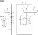
- Fig.3 shows the front view of a door leaf 26 or the cover plate 27 of the door leaf 26 in the area of the mounted handle set 28, which here includes a short plate 32.
- the latch 30, the short plate 32 and the cylinder hole 36 in the short plate 32 are visible here. Not visible are the base plate 56 and the cylinder cutout 44 and the short plate cutout 48 in the cover plate 27, which are covered by the large cover plate 12 and the short plate 32.
- the handle base plate 56 arranged under the short plate 32 is screwed to the cover plate 27 of the door leaf 26 with two screws 34 through two base plate holes 58 in the base plate 56.
- the large cover plate 12 is fixed in a sandwich structure between the screwed base plate 56 and the door leaf 26.
- the screwed base plate 56 presses the large cover plate 12 against the door leaf 26 or the cover plate 27 and ensures the smoke-tight closure of the cylinder cutout 44 and the locking cylinder recess 20.
- the large cover plate 12 corresponds to the Fig.1 shown large cover plate 12 and has three cover element holes 16 with the Fig.1 shown cover element hole pattern 14.
- the large cover plate 12 provided with double-sided adhesive tape 22 is glued to the cover plate 27 of the door leaf 26 in such a way that its central area covers the cylinder cutout 44 and the locking cylinder recess 20 and the lower cover element hole 16 is arranged symmetrically in the middle on a vertical center line of the locking cylinder recess 20.
- the base plate 56 is then fixed to the cover plate 27 of the door leaf 26 using two screws 34.
- the lower screw 34 is guided through the lower base plate hole 58 and through the lower cover element hole 16 in the large cover plate 12.
- the large cover plate 12 is firmly fixed between the base plate 56 and the door leaf 26, thus sealing the locking cylinder recess 20 in the door leaf 26 in a smoke-tight manner.
- the two upper locking element holes 14 remain inoperative when the short plate 32 is used and protrude to the left when the handle set 28 is fully assembled. and partially protrudes to the right of the short plate 30. Likewise, the large cover plate 12 protrudes clearly as a rectangle to the left and right under the fitting.
- This arrangement of handle 30, short plate 32, screws 34 on door leaf 26 or cover plate 27 of door leaf 26 is illustrated in the side view to the left of the front view.
- An enlarged detail at X shows in detail the sandwich structure of short plate 32 (underneath which the base plate 56 is hidden), large cover plate 12 with a thickness d of, for example, 0.5 mm and cover plate 27.
- FIG.4 Another embodiment of a smoke protection door is shown after installation of the smoke protection door kit.
- the difference to the Fig.3 The embodiment shown consists in that, instead of the short plate 32, a rosette fitting consisting of a latch rosette 38 and a cylinder rosette 40 is used and correspondingly shaped base plates 56 are used under the two rosettes 38, 40.
- the base plate 56 of the cylinder rosette 40 has two screw holes (not visible) to the left and right of the cylinder hole 36 in the cylinder rosette 40, through which the base plate 56 is screwed to the cover plate 27.
- the base plate 56 of the rosette fitting for screwing has a different hole pattern than the base plate 56 of the short plate 32, the same large cover plate 12 as in the embodiment of Fig.3 Instead of the lower cover element hole 16, the two upper cover element holes 16 are now used for screwing on the base plate 56 (see Fig.1 ). In this embodiment, the lower of the three cover element holes 16 remains inoperative and protrudes below the cylinder rosette 40.
- the hole pattern of the base plates 56 differs considerably in a fitting with a short plate 32 and a rosette fitting 38, 40, the same flat cover element 10 or large cover plate 12 can be used to produce the smoke-tight closure of the locking cylinder recess 20, because the flat cover element 10 has a cover element hole pattern 14 that is compatible with both basic plate hole patterns.
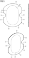
- Fig.5 shows a second embodiment of a flat cover element 10 in the form of a small cover plate 42.
- the small cover plate 12 has, as a cover element contour 18, two opposing curved edges in the form of circular arcs 50 of equal size, which are connected to one another by two predominantly parallel and overall mirror-image straight edges 52.
- Semicircular cover element recesses 54 are provided in the middle of the parallel straight edges.
- the drawing of the small cover plate 42 has a dashed line in the shape of an elongated circle in the central position. This area corresponds to the cylinder cutout 44 which is formed in the cover plate of the door leaf 26 to accommodate the locking cylinder and which, when installed, is closed off smoke-tight by the small cover plate 42.
- the base plate 56 and the small cover plate 42 By screwing the base plate 56 and the small cover plate 42 over the cover plate cylinder cutout 44, the locking cylinder recess 20 in the door leaf 26 is closed off smoke-tight without a locking cylinder or a dummy cylinder having to be inserted into the recess.
- the double-sided adhesive tape 22 is formed here without any protruding release film.
- Fig.5 Below the front view of the small cover plate 42 is a perspective view of the small cover plate 42.
- Fig.6 illustrates the use of the small cover plate 42 according to Fig.5 for a smoke protection door with short plate handle set.
- the use of the small cover plate 42 is the only and essential difference to the Fig.3 All other components and reference symbols correspond to Fig.3 so that in this respect Fig.3 can be referred to.
- the upper illustration shows the front view and the side view of the door leaf in the area of the handle, the lower illustration shows a rear view of the door leaf in the area of the handle without the box sheet that is actually present.
- the small cover plate 42 has such dimensions that it is completely covered by the short plate 32. This gives an aesthetic overall impression while maintaining a good smoke-tight closure of the cylinder cutout 44 and the locking cylinder recess 20.
- the rear view of the door leaf 26 illustrates the precise arrangement of the small cover plate 42 between the base plate 56 and the door leaf 26.
- the small cover plate 42 can be fitted with its parallel vertical edges exactly into the short plate 32 with its vertical parallel edges. It lies flat on the base plate 56. Due to the arrangement of the two base plate holes 58 in the base plate 52 below and above the small cover plate 42, the cover element recesses 54 in the small cover plate 42 are inoperative. Due to the sufficiently large distance between the base plate holes 58 in the base plate 52 and the cylinder hole 36 in the base plate 52 and at the same time the sufficiently small dimensions of the small cover plate 42, the screwing of the base plate 56 to the door leaf 26 is not hindered by the small cover plate 42. Thus, no further cover element holes 16 need to be provided in the small cover plate 42, as in the embodiment according to Fig.1 and Fig.3 are required.
- the side view of the embodiment according to Fig.6 shows that the small cover plate 42 has such dimensions that it fits completely in the recess of the Short shield 32 disappears. Unlike in Fig.3 The small cover plate 42 does not add any bulk at all.
- the small cover plate 42 For the installation of the small cover plate 42, it is advantageous to provide the small cover plate with a double-sided adhesive tape 22 without a pull-off tab. After removing the protective film of the double-sided adhesive tape 22, the small cover plate 42 is glued either over the cylinder cutout 44 onto the door leaf 26 or onto the base plate 56.
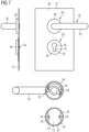
- Fig.7 illustrates the use of the small cover plate 42 according to Fig.5 for a smoke protection door with rosette fitting.
- the use of the small cover plate 42 instead of the large cover plate 12 is the only and essential difference to the Fig.4 Since all other components and reference numerals are Fig.4 can be referred to the description of the embodiment according to Fig.4 can be referred to.
- the upper illustration in Fig.7 shows the front view and the side view of the door leaf 26 in the area of the handle.
- the lower illustration shows a rear view of the door leaf 26 in the area of the handle without the box sheet that is actually present.
- FIG.7 shows that the small cover plate 42 has such dimensions that it is completely covered by the cylinder rosette 40. This gives an overall aesthetic impression while maintaining a good smoke-tight closure of the cylinder cutout 44 and the locking cylinder recess 20.
- the rear view of the door leaf 26 illustrates the precise arrangement of the small cover plate 42 between the base plate 56 of the cylinder rosette 40 and the door leaf 26.
- the small cover plate 42 with its basic shape derived from a circle, fits exactly into the recess of the circular and slightly larger cylinder rosette 40. It lies flat on the circular base plate 56.
- the two base plate holes 58 are arranged in the base plate 56 to the left and right of the invisible cylinder hole 36.
- the recesses 54 in the small cover plate 42 enable the base plate 56 to be screwed to the door leaf 26 without hindrance.
- Cover element holes 16 are not required due to the cover element contour 18. This represents a significant difference to the embodiment according to Fig.1 and Fig.4 in which the large cover plate 12 has a cover element hole pattern 14 which enables the base plate to be screwed to the door leaf 26.
- the side view of the embodiment according to Fig.7 shows that the small cover plate 42 has such dimensions that it completely disappears in the recess of the cylinder rosette 40. Unlike in Fig.5 the small cover plate 42 does not add any bulk at all.
- the hole pattern of the base plates 56 and their contour differ considerably in a short plate 32 and a rosette fitting consisting of a handle rosette 38 and a cylinder rosette 40, the same small cover plate 42 can be used to create the smoke-tight closure of the locking cylinder recess 20 during the initial assembly of the smoke protection door using the smoke protection door kit, because the small cover plate 42 has the cover element contour 18 required for this.
- cover element contour 18 By further refining the cover element contour 18 and, if necessary, providing a more universal hole pattern in the flat cover element 10, it is possible to also cover the handle hole pattern of other handle sets, such as H8-5. With appropriate design, many different smoke protection door assemblies with different handle sets and different handle hole patterns can be equipped with a single flat cover element 10.
Landscapes
- Engineering & Computer Science (AREA)
- Structural Engineering (AREA)
- Physics & Mathematics (AREA)
- Thermal Sciences (AREA)
- Civil Engineering (AREA)
- Special Wing (AREA)
- Casings For Electric Apparatus (AREA)
- Specific Sealing Or Ventilating Devices For Doors And Windows (AREA)
Priority Applications (1)
| Application Number | Priority Date | Filing Date | Title |
|---|---|---|---|
| EP24176921.5A EP4394150A3 (de) | 2018-12-19 | 2019-12-16 | Rauchschutztür-bausatz zum bilden einer rauchschutztür mit verschlusselement zum rauchdichten verschliessen der schliesszylinderaussparung |
Applications Claiming Priority (1)
| Application Number | Priority Date | Filing Date | Title |
|---|---|---|---|
| DE102018132985.7A DE102018132985A1 (de) | 2018-12-19 | 2018-12-19 | Rauchschutztür-Bausatz zum Bilden einer Rauchschutztür mit Verschlusselement zum rauchdichten Verschließen der Schließzylinderaussparung |
Related Child Applications (2)
| Application Number | Title | Priority Date | Filing Date |
|---|---|---|---|
| EP24176921.5A Division EP4394150A3 (de) | 2018-12-19 | 2019-12-16 | Rauchschutztür-bausatz zum bilden einer rauchschutztür mit verschlusselement zum rauchdichten verschliessen der schliesszylinderaussparung |
| EP24176921.5A Division-Into EP4394150A3 (de) | 2018-12-19 | 2019-12-16 | Rauchschutztür-bausatz zum bilden einer rauchschutztür mit verschlusselement zum rauchdichten verschliessen der schliesszylinderaussparung |
Publications (3)
| Publication Number | Publication Date |
|---|---|
| EP3670812A1 EP3670812A1 (de) | 2020-06-24 |
| EP3670812C0 EP3670812C0 (de) | 2024-08-14 |
| EP3670812B1 true EP3670812B1 (de) | 2024-08-14 |
Family
ID=68917542
Family Applications (2)
| Application Number | Title | Priority Date | Filing Date |
|---|---|---|---|
| EP24176921.5A Pending EP4394150A3 (de) | 2018-12-19 | 2019-12-16 | Rauchschutztür-bausatz zum bilden einer rauchschutztür mit verschlusselement zum rauchdichten verschliessen der schliesszylinderaussparung |
| EP19216440.8A Active EP3670812B1 (de) | 2018-12-19 | 2019-12-16 | Rauchschutztür-bausatz zum bilden einer rauchschutztür mit verschlusselement zum rauchdichten verschliessen der schliesszylinderaussparung |
Family Applications Before (1)
| Application Number | Title | Priority Date | Filing Date |
|---|---|---|---|
| EP24176921.5A Pending EP4394150A3 (de) | 2018-12-19 | 2019-12-16 | Rauchschutztür-bausatz zum bilden einer rauchschutztür mit verschlusselement zum rauchdichten verschliessen der schliesszylinderaussparung |
Country Status (4)
| Country | Link |
|---|---|
| EP (2) | EP4394150A3 (pl) |
| DE (1) | DE102018132985A1 (pl) |
| ES (1) | ES2987283T3 (pl) |
| PL (1) | PL3670812T3 (pl) |
Families Citing this family (1)
| Publication number | Priority date | Publication date | Assignee | Title |
|---|---|---|---|---|
| DE102024107606A1 (de) | 2024-03-18 | 2025-09-18 | Eco Schulte Gmbh & Co. Kg | Abdichtelement für einen Beschlag zum flamm- und rauchgasdichten Verschließen einer Schließzylinderausnehmung des Beschlags |
Family Cites Families (8)
| Publication number | Priority date | Publication date | Assignee | Title |
|---|---|---|---|---|
| DE2607248A1 (de) * | 1975-02-26 | 1976-09-09 | Horst Peter Dipl Ing Seiffarth | Anordnung bei einer feuerhemmenden tuere o.dgl. durchgangsoeffnung |
| DE8102621U1 (de) * | 1981-02-03 | 1981-07-09 | Echt & Co, Nachf. Schulte Kg, 5750 Menden | "tuerschild fuer eine feuerschutztuer o.dgl. |
| DE3530876A1 (de) * | 1984-10-19 | 1986-04-24 | Lothar Laflör GmbH & Co, 5620 Velbert | Tuerschloss fuer feuerhemmende tueren |
| DE8700069U1 (de) * | 1987-01-02 | 1988-04-28 | Hörmann KG Freisen, 6699 Freisen | Unterschild einer Türdrückergarnitur für Feuerschutztüren |
| DE8803208U1 (de) * | 1988-03-10 | 1988-04-28 | Paul Schmitz GmbH, 5200 Siegburg | Stahltür |
| CA2177550A1 (en) * | 1995-05-31 | 1996-12-01 | Khurshid A. Qureshi | Door handle modular return spring cage assembly |
| FR2807094B1 (fr) * | 2000-03-31 | 2003-07-04 | Claude Vlaeminck | Porte coupe-feu |
| DE102007019883A1 (de) * | 2007-04-27 | 2008-11-06 | Fa. Meusel + Beck | Zier- Steckverschluß für Schlüssellöcher |
-
2018
- 2018-12-19 DE DE102018132985.7A patent/DE102018132985A1/de active Pending
-
2019
- 2019-12-16 EP EP24176921.5A patent/EP4394150A3/de active Pending
- 2019-12-16 PL PL19216440.8T patent/PL3670812T3/pl unknown
- 2019-12-16 EP EP19216440.8A patent/EP3670812B1/de active Active
- 2019-12-16 ES ES19216440T patent/ES2987283T3/es active Active
Also Published As
| Publication number | Publication date |
|---|---|
| EP4394150A3 (de) | 2024-09-04 |
| ES2987283T3 (es) | 2024-11-14 |
| DE102018132985A1 (de) | 2020-06-25 |
| EP4394150A2 (de) | 2024-07-03 |
| EP3670812C0 (de) | 2024-08-14 |
| PL3670812T3 (pl) | 2024-12-16 |
| EP3670812A1 (de) | 2020-06-24 |
Similar Documents
| Publication | Publication Date | Title |
|---|---|---|
| DE102020131834A1 (de) | Tür, insbesondere Haustür und Verfahren zur Herstellung eines Türflügels für eine solche Tür | |
| DE102012108931A1 (de) | Verfahren zum Herstellen eines Gebäudetür-Türblatts sowie damit herstellbares Türblatt | |
| EP3670812B1 (de) | Rauchschutztür-bausatz zum bilden einer rauchschutztür mit verschlusselement zum rauchdichten verschliessen der schliesszylinderaussparung | |
| DE202013007293U1 (de) | Feuerbeständige System-Trennwand | |
| EP0078905B1 (de) | Umfassungszarge zur Verkleidung einer Wandöffnung für eine Tür oder dergleichen | |
| EP2372069B1 (de) | Brandschutz-Türzarge aus Holz | |
| DE102018114378B4 (de) | Anordnung zur Sicherung von nach innen zu öffnenden Fenstern und Türen gegen Einbrüche | |
| DE202020105543U1 (de) | Vormontagezarge zum Einbauen in eine Öffnung oder an einen Abschluss einer Wandung sowie Wandung-Vormontagezargen-Anordnung | |
| DE202008016782U1 (de) | Schließeinrichtung für Brandschutztüren oder -fenster | |
| DE19937835A1 (de) | Feuerschutzsystem | |
| DE102013101649A1 (de) | Bauteilanordnung, Profileinheit und Verfahren zum Dämmen einer Einbaueinheit | |
| DE102013105344A1 (de) | Türblatt für eine Türanordnung | |
| DE102004040749B4 (de) | Rauchschutzabschlusssystem | |
| DE202006018641U1 (de) | Brandschutztürsystem | |
| DE19838458C2 (de) | Nachrüstzarge für einen Türrahmen und ein Türblatt | |
| DE3905886A1 (de) | Feuer- und schallhemmende tuer | |
| EP3789577A1 (de) | Brandschutztür, türblatt, zarge, verfahren zur herstellung der brandschutztür | |
| EP1491702A1 (de) | Revisionsabdeckung | |
| EP2889441A2 (de) | VERFAHREN ZUM VERSCHLIEßEN VON GERÜSTANKERLÖCHERN | |
| DE202006004425U1 (de) | Rahmenbaugruppe | |
| DE8812475U1 (de) | Luftdurchlaß mit einer Absperrvorrichtung gegen Feuer und Rauch (Brandschutzklappe) für eine Decke | |
| EP2828443B1 (de) | Bauteilanordnung zum dämmen einer einbaueinheit | |
| DE20219687U1 (de) | Brandschutztür | |
| DE10358022B4 (de) | Fußprofil mit Durchbrandschutz | |
| AT501601B1 (de) | Zarge mit an dieser angelenktem/n flügel/n |
Legal Events
| Date | Code | Title | Description |
|---|---|---|---|
| PUAI | Public reference made under article 153(3) epc to a published international application that has entered the european phase |
Free format text: ORIGINAL CODE: 0009012 |
|
| STAA | Information on the status of an ep patent application or granted ep patent |
Free format text: STATUS: THE APPLICATION HAS BEEN PUBLISHED |
|
| AK | Designated contracting states |
Kind code of ref document: A1 Designated state(s): AL AT BE BG CH CY CZ DE DK EE ES FI FR GB GR HR HU IE IS IT LI LT LU LV MC MK MT NL NO PL PT RO RS SE SI SK SM TR |
|
| AX | Request for extension of the european patent |
Extension state: BA ME |
|
| STAA | Information on the status of an ep patent application or granted ep patent |
Free format text: STATUS: REQUEST FOR EXAMINATION WAS MADE |
|
| 17P | Request for examination filed |
Effective date: 20201210 |
|
| RBV | Designated contracting states (corrected) |
Designated state(s): AL AT BE BG CH CY CZ DE DK EE ES FI FR GB GR HR HU IE IS IT LI LT LU LV MC MK MT NL NO PL PT RO RS SE SI SK SM TR |
|
| STAA | Information on the status of an ep patent application or granted ep patent |
Free format text: STATUS: EXAMINATION IS IN PROGRESS |
|
| 17Q | First examination report despatched |
Effective date: 20230404 |
|
| P01 | Opt-out of the competence of the unified patent court (upc) registered |
Effective date: 20230512 |
|
| GRAP | Despatch of communication of intention to grant a patent |
Free format text: ORIGINAL CODE: EPIDOSNIGR1 |
|
| STAA | Information on the status of an ep patent application or granted ep patent |
Free format text: STATUS: GRANT OF PATENT IS INTENDED |
|
| RIC1 | Information provided on ipc code assigned before grant |
Ipc: E05B 15/02 20060101ALI20240419BHEP Ipc: E06B 3/70 20060101ALI20240419BHEP Ipc: E05B 63/00 20060101ALI20240419BHEP Ipc: E05B 17/00 20060101ALI20240419BHEP Ipc: E06B 5/16 20060101AFI20240419BHEP |
|
| INTG | Intention to grant announced |
Effective date: 20240514 |
|
| GRAS | Grant fee paid |
Free format text: ORIGINAL CODE: EPIDOSNIGR3 |
|
| GRAA | (expected) grant |
Free format text: ORIGINAL CODE: 0009210 |
|
| STAA | Information on the status of an ep patent application or granted ep patent |
Free format text: STATUS: THE PATENT HAS BEEN GRANTED |
|
| AK | Designated contracting states |
Kind code of ref document: B1 Designated state(s): AL AT BE BG CH CY CZ DE DK EE ES FI FR GB GR HR HU IE IS IT LI LT LU LV MC MK MT NL NO PL PT RO RS SE SI SK SM TR |
|
| REG | Reference to a national code |
Ref country code: GB Ref legal event code: FG4D Free format text: NOT ENGLISH |
|
| REG | Reference to a national code |
Ref country code: CH Ref legal event code: EP |
|
| REG | Reference to a national code |
Ref country code: DE Ref legal event code: R096 Ref document number: 502019011880 Country of ref document: DE |
|
| REG | Reference to a national code |
Ref country code: IE Ref legal event code: FG4D Free format text: LANGUAGE OF EP DOCUMENT: GERMAN |
|
| U01 | Request for unitary effect filed |
Effective date: 20240911 |
|
| U07 | Unitary effect registered |
Designated state(s): AT BE BG DE DK EE FI FR IT LT LU LV MT NL PT RO SE SI Effective date: 20240926 |
|
| P04 | Withdrawal of opt-out of the competence of the unified patent court (upc) registered |
Free format text: CASE NUMBER: APP_53097/2024 Effective date: 20240923 |
|
| REG | Reference to a national code |
Ref country code: ES Ref legal event code: FG2A Ref document number: 2987283 Country of ref document: ES Kind code of ref document: T3 Effective date: 20241114 |
|
| P05 | Withdrawal of opt-out of the competence of the unified patent court (upc) changed |
Free format text: CASE NUMBER: APP_53097/2024 Effective date: 20240926 |
|
| PG25 | Lapsed in a contracting state [announced via postgrant information from national office to epo] |
Ref country code: NO Free format text: LAPSE BECAUSE OF FAILURE TO SUBMIT A TRANSLATION OF THE DESCRIPTION OR TO PAY THE FEE WITHIN THE PRESCRIBED TIME-LIMIT Effective date: 20241114 |
|
| PG25 | Lapsed in a contracting state [announced via postgrant information from national office to epo] |
Ref country code: GR Free format text: LAPSE BECAUSE OF FAILURE TO SUBMIT A TRANSLATION OF THE DESCRIPTION OR TO PAY THE FEE WITHIN THE PRESCRIBED TIME-LIMIT Effective date: 20241115 |
|
| U20 | Renewal fee for the european patent with unitary effect paid |
Year of fee payment: 6 Effective date: 20241218 |
|
| PG25 | Lapsed in a contracting state [announced via postgrant information from national office to epo] |
Ref country code: IS Free format text: LAPSE BECAUSE OF FAILURE TO SUBMIT A TRANSLATION OF THE DESCRIPTION OR TO PAY THE FEE WITHIN THE PRESCRIBED TIME-LIMIT Effective date: 20241214 |
|
| PG25 | Lapsed in a contracting state [announced via postgrant information from national office to epo] |
Ref country code: HR Free format text: LAPSE BECAUSE OF FAILURE TO SUBMIT A TRANSLATION OF THE DESCRIPTION OR TO PAY THE FEE WITHIN THE PRESCRIBED TIME-LIMIT Effective date: 20240814 |
|
| PG25 | Lapsed in a contracting state [announced via postgrant information from national office to epo] |
Ref country code: RS Free format text: LAPSE BECAUSE OF FAILURE TO SUBMIT A TRANSLATION OF THE DESCRIPTION OR TO PAY THE FEE WITHIN THE PRESCRIBED TIME-LIMIT Effective date: 20241114 |
|
| PG25 | Lapsed in a contracting state [announced via postgrant information from national office to epo] |
Ref country code: RS Free format text: LAPSE BECAUSE OF FAILURE TO SUBMIT A TRANSLATION OF THE DESCRIPTION OR TO PAY THE FEE WITHIN THE PRESCRIBED TIME-LIMIT Effective date: 20241114 Ref country code: NO Free format text: LAPSE BECAUSE OF FAILURE TO SUBMIT A TRANSLATION OF THE DESCRIPTION OR TO PAY THE FEE WITHIN THE PRESCRIBED TIME-LIMIT Effective date: 20241114 Ref country code: IS Free format text: LAPSE BECAUSE OF FAILURE TO SUBMIT A TRANSLATION OF THE DESCRIPTION OR TO PAY THE FEE WITHIN THE PRESCRIBED TIME-LIMIT Effective date: 20241214 Ref country code: HR Free format text: LAPSE BECAUSE OF FAILURE TO SUBMIT A TRANSLATION OF THE DESCRIPTION OR TO PAY THE FEE WITHIN THE PRESCRIBED TIME-LIMIT Effective date: 20240814 Ref country code: GR Free format text: LAPSE BECAUSE OF FAILURE TO SUBMIT A TRANSLATION OF THE DESCRIPTION OR TO PAY THE FEE WITHIN THE PRESCRIBED TIME-LIMIT Effective date: 20241115 |
|
| PG25 | Lapsed in a contracting state [announced via postgrant information from national office to epo] |
Ref country code: SM Free format text: LAPSE BECAUSE OF FAILURE TO SUBMIT A TRANSLATION OF THE DESCRIPTION OR TO PAY THE FEE WITHIN THE PRESCRIBED TIME-LIMIT Effective date: 20240814 |
|
| PG25 | Lapsed in a contracting state [announced via postgrant information from national office to epo] |
Ref country code: CZ Free format text: LAPSE BECAUSE OF FAILURE TO SUBMIT A TRANSLATION OF THE DESCRIPTION OR TO PAY THE FEE WITHIN THE PRESCRIBED TIME-LIMIT Effective date: 20240814 |
|
| PG25 | Lapsed in a contracting state [announced via postgrant information from national office to epo] |
Ref country code: SK Free format text: LAPSE BECAUSE OF FAILURE TO SUBMIT A TRANSLATION OF THE DESCRIPTION OR TO PAY THE FEE WITHIN THE PRESCRIBED TIME-LIMIT Effective date: 20240814 |
|
| PLBE | No opposition filed within time limit |
Free format text: ORIGINAL CODE: 0009261 |
|
| STAA | Information on the status of an ep patent application or granted ep patent |
Free format text: STATUS: NO OPPOSITION FILED WITHIN TIME LIMIT |
|
| PG25 | Lapsed in a contracting state [announced via postgrant information from national office to epo] |
Ref country code: MC Free format text: LAPSE BECAUSE OF FAILURE TO SUBMIT A TRANSLATION OF THE DESCRIPTION OR TO PAY THE FEE WITHIN THE PRESCRIBED TIME-LIMIT Effective date: 20240814 |
|
| 26N | No opposition filed |
Effective date: 20250515 |
|
| REG | Reference to a national code |
Ref country code: CH Ref legal event code: PL |
|
| GBPC | Gb: european patent ceased through non-payment of renewal fee |
Effective date: 20241216 |
|
| PG25 | Lapsed in a contracting state [announced via postgrant information from national office to epo] |
Ref country code: GB Free format text: LAPSE BECAUSE OF NON-PAYMENT OF DUE FEES Effective date: 20241216 |
|
| PG25 | Lapsed in a contracting state [announced via postgrant information from national office to epo] |
Ref country code: CH Free format text: LAPSE BECAUSE OF NON-PAYMENT OF DUE FEES Effective date: 20241231 |
|
| PG25 | Lapsed in a contracting state [announced via postgrant information from national office to epo] |
Ref country code: IE Free format text: LAPSE BECAUSE OF NON-PAYMENT OF DUE FEES Effective date: 20241216 |
|
| U20 | Renewal fee for the european patent with unitary effect paid |
Year of fee payment: 7 Effective date: 20251216 |
|
| PGFP | Annual fee paid to national office [announced via postgrant information from national office to epo] |
Ref country code: PL Payment date: 20251208 Year of fee payment: 7 |
|
| PGFP | Annual fee paid to national office [announced via postgrant information from national office to epo] |
Ref country code: ES Payment date: 20260119 Year of fee payment: 7 |