EP3670819A1 - Rideau de panneau - Google Patents
Rideau de panneau Download PDFInfo
- Publication number
- EP3670819A1 EP3670819A1 EP18214946.8A EP18214946A EP3670819A1 EP 3670819 A1 EP3670819 A1 EP 3670819A1 EP 18214946 A EP18214946 A EP 18214946A EP 3670819 A1 EP3670819 A1 EP 3670819A1
- Authority
- EP
- European Patent Office
- Prior art keywords
- sliding
- rail
- panel
- groove
- block
- Prior art date
- Legal status (The legal status is an assumption and is not a legal conclusion. Google has not performed a legal analysis and makes no representation as to the accuracy of the status listed.)
- Granted
Links
Images


Classifications
-
- E—FIXED CONSTRUCTIONS
- E06—DOORS, WINDOWS, SHUTTERS, OR ROLLER BLINDS IN GENERAL; LADDERS
- E06B—FIXED OR MOVABLE CLOSURES FOR OPENINGS IN BUILDINGS, VEHICLES, FENCES OR LIKE ENCLOSURES IN GENERAL, e.g. DOORS, WINDOWS, BLINDS, GATES
- E06B9/00—Screening or protective devices for wall or similar openings, with or without operating or securing mechanisms; Closures of similar construction
- E06B9/24—Screens or other constructions affording protection against light, especially against sunshine; Similar screens for privacy or appearance; Slat blinds
- E06B9/26—Lamellar or like blinds, e.g. venetian blinds
- E06B9/36—Lamellar or like blinds, e.g. venetian blinds with vertical lamellae ; Supporting rails therefor
-
- A—HUMAN NECESSITIES
- A47—FURNITURE; DOMESTIC ARTICLES OR APPLIANCES; COFFEE MILLS; SPICE MILLS; SUCTION CLEANERS IN GENERAL
- A47H—FURNISHINGS FOR WINDOWS OR DOORS
- A47H1/00—Curtain suspension devices
- A47H1/04—Curtain rails
-
- A—HUMAN NECESSITIES
- A47—FURNITURE; DOMESTIC ARTICLES OR APPLIANCES; COFFEE MILLS; SPICE MILLS; SUCTION CLEANERS IN GENERAL
- A47H—FURNISHINGS FOR WINDOWS OR DOORS
- A47H1/00—Curtain suspension devices
- A47H1/04—Curtain rails
- A47H1/08—Curtain rails extensible
-
- A—HUMAN NECESSITIES
- A47—FURNITURE; DOMESTIC ARTICLES OR APPLIANCES; COFFEE MILLS; SPICE MILLS; SUCTION CLEANERS IN GENERAL
- A47H—FURNISHINGS FOR WINDOWS OR DOORS
- A47H13/00—Fastening curtains on curtain rods or rails
- A47H13/01—Fastening curtains on curtain rods or rails by clamps; by clamps attached to hooks or rings
-
- A—HUMAN NECESSITIES
- A47—FURNITURE; DOMESTIC ARTICLES OR APPLIANCES; COFFEE MILLS; SPICE MILLS; SUCTION CLEANERS IN GENERAL
- A47H—FURNISHINGS FOR WINDOWS OR DOORS
- A47H2/00—Pelmets or the like
-
- A—HUMAN NECESSITIES
- A47—FURNITURE; DOMESTIC ARTICLES OR APPLIANCES; COFFEE MILLS; SPICE MILLS; SUCTION CLEANERS IN GENERAL
- A47H—FURNISHINGS FOR WINDOWS OR DOORS
- A47H1/00—Curtain suspension devices
- A47H2001/003—Constructional details common to rods or rails
- A47H2001/006—End-stops, i.e. devices preventing the curtain falling off the end of the rail or rod
-
- A—HUMAN NECESSITIES
- A47—FURNITURE; DOMESTIC ARTICLES OR APPLIANCES; COFFEE MILLS; SPICE MILLS; SUCTION CLEANERS IN GENERAL
- A47H—FURNISHINGS FOR WINDOWS OR DOORS
- A47H1/00—Curtain suspension devices
- A47H1/04—Curtain rails
- A47H2001/047—Curtain rails with multiple tracks
-
- A—HUMAN NECESSITIES
- A47—FURNITURE; DOMESTIC ARTICLES OR APPLIANCES; COFFEE MILLS; SPICE MILLS; SUCTION CLEANERS IN GENERAL
- A47H—FURNISHINGS FOR WINDOWS OR DOORS
- A47H23/00—Curtains; Draperies
- A47H23/02—Shapes of curtains; Selection of particular materials for curtains
- A47H2023/025—Panel type curtains
-
- A—HUMAN NECESSITIES
- A47—FURNITURE; DOMESTIC ARTICLES OR APPLIANCES; COFFEE MILLS; SPICE MILLS; SUCTION CLEANERS IN GENERAL
- A47H—FURNISHINGS FOR WINDOWS OR DOORS
- A47H2201/00—Means for connecting curtains
- A47H2201/02—Hook-and-loop fasteners
-
- E—FIXED CONSTRUCTIONS
- E06—DOORS, WINDOWS, SHUTTERS, OR ROLLER BLINDS IN GENERAL; LADDERS
- E06B—FIXED OR MOVABLE CLOSURES FOR OPENINGS IN BUILDINGS, VEHICLES, FENCES OR LIKE ENCLOSURES IN GENERAL, e.g. DOORS, WINDOWS, BLINDS, GATES
- E06B9/00—Screening or protective devices for wall or similar openings, with or without operating or securing mechanisms; Closures of similar construction
- E06B9/24—Screens or other constructions affording protection against light, especially against sunshine; Similar screens for privacy or appearance; Slat blinds
- E06B9/26—Lamellar or like blinds, e.g. venetian blinds
- E06B9/36—Lamellar or like blinds, e.g. venetian blinds with vertical lamellae ; Supporting rails therefor
- E06B9/362—Travellers; Lamellae suspension stems
Definitions
- the present invention relates to a curtain, especially to a panel curtain.
- a conventional panel curtain 40 includes a support base 41, a plurality of rail channels 42, a plurality of sliding rails 43, a plurality of panels 44 and a cord 45.
- the rail channels 42 are disposed on the support base 41 and spaced from each other (there are three in the figure) while each of the sliding rails 43 is mounted on the respective rail channel 42 correspondingly.
- Each of the sliding rails 43 is provided with two pulleys 431 on top thereof and mounted in the rail channel 42 by the two pulleys 431.
- the panels 44 are mounted on the sliding rails 43 respectively.
- the cord 45 is disposed on the support base 41 for driving one of the sliding wheels 431.
- a plurality of limiting blocks 432 is arranged at the sliding rails 43 respectively in a staggered manner for limiting movement among the sliding rails 43.
- the above structure of the conventional panel curtain still has certain shortcomings.
- the main one is that the sliding rail 43 is slidably mounted in the rail channel 42 of the support base 41 by means of the pulleys 431 so that the size of the rail channel 42 of the support base 41 must be increased in order to match the size of the sliding wheels 431.
- the production costs and the packaging volume of the support base 41 are increased.
- the assembly is more difficult.
- a panel curtain according to the present invention includes an upper track, at least one rail set and a plurality of panels.
- the upper track is composed of an inner track and an outer track, whereas the inner und outer track are inserted into each other in such a manner that the upper track is telescopically adjustable in length.
- Two rail channels are disposed on the inner track and the outer track, respectively at the same side and communicating with each other.
- a plurality of clips is arranged at the top of the upper track.
- An assembly portion is disposed on the lateral surface of each of the clips and used for fixing two touch fasteners.
- a curtain fabric is affixed to the two touch fasteners.
- the rail set consists of a plurality of sliding rails arranged in parallel.
- Each of the sliding rails is provided with a positioning groove and a limiting groove that are disposed on two lateral surfaces thereof respectively and corresponding to each other while a panel groove is arranged at the bottom of the respective sliding rail.
- a sliding block is fixed on the distal end of the positioning groove of the respective sliding rail and a barrier piece is extending downward from the sliding block for covering one end of the panel groove.
- the sliding block is slidably mounted in the limiting groove of the adjacent sliding rail and a limiting block with a buffer spring is disposed on the front end of the limiting groove of the respective sliding rail while a swiveling stopper is pivotally mounted on the distal end of the limiting block.
- a connecting rib is disposed on the top of the respective sliding rail, whereas a plurality of punch holes is arranged on the respective connecting rib in turn.
- a connecting sliding block is mounted on the front end of the connecting rib of the respective sliding rail and is provided with a sliding locking portion and a connecting portion. The length of the connecting portion varies depending on the position of the respective sliding rail among the sliding rails in parallel. Thereby the respective connecting sliding block is fixed on the connecting rib of the corresponding sliding rail by the connecting portion in such a manner that the sliding locking portions are aligned and abut against one another.
- the frontmost connecting sliding block is disposed on the sliding rail that is defined as the first one according to the sequential arrangement and is further provided with a cord binding portion while a positioning block is arranged at the distal end of the connecting rib of the sliding rail that is defined as the last one according to the sequential arrangement.
- the positioning block is further fixed and limited on the upper track.
- a panel holding portion is formed on the top of the respective panel and slidably mounted in the panel groove of the respective sliding rail in such a manner that the panel holding portion is limited and positioned by the barrier piece and the stopper on two ends of the respective panel groove.
- a snapping portion is formed on the top of the inner track and the top of the outer track respectively.
- Each of the clips is provided with a locking portion and an assembly portion vertically extending from the front end of the clip.
- the assembly portion is formed in such a manner that two limiting channels are arranged correspondingly on the upper and lower front side for limiting and positioning the two touch fasteners.
- the positioning block is provided with a sliding locking portion that is slidably mounted in the rail channel of the upper track correspondingly.
- a packing piece is disposed at the sliding locking portion in such a manner that the packing piece is facing the opening of the rail channel.
- the packing piece is used in combination with a fastener and friction-locked by screwing the fastener.
- an insertion hole is arranged at the respective connecting sliding block in such a manner that the insertion hole is facing the opening of the rail channel.
- the Insertion hole is used in combination with a linking piece for connecting at least two connecting sliding blocks. Thus at least two sliding rails are linked.
- the linking piece is provided with at least two pins corresponding to the connecting sliding blocks.
- the sliding block is provided with two symmetrical limiting pieces facing the limiting groove of the adjacent sliding rail.
- the panel curtain includes two rail sets that are mounted on the outermost end of the inner track and the outermost end of the outer track respectively and linked to be moved toward each other for closing and away from each other for opening.
- the sliding rails of the two rail sets are not aligned and a gap is formed therebetween so that the two rail sets are staggered to be in a closed state when the first sliding rails thereof are leaning against each other.
- a staggering spring is arranged at the front end of the sliding rail located at the inner side for keeping the above two sliding rails in the staggered state when the sliding rails are staggered.
- the upper track is used in combination with a cord for sliding and moving the rail set.
- the panel curtain of the present invention has the following advantages.
- a connecting sliding block is disposed on each of the sliding rails of the respective rail set and is provided with a connecting portion whose length varies depending on the order of the sliding rail among the sliding rails in parallel.
- the connecting portions are used for allowing the sliding locking portions to be aligned and mounted in the rail channel of the upper track after the connecting sliding blocks and the sliding rails being assembled. Thereby volume and size of the upper track are significantly decreased and the packaging volume is effectively reduced.
- a sliding block is fixed on the distal end of the positioning groove of the respective sliding rail and a barrier piece is extending downward from the sliding block for covering one end of the panel groove.
- a limiting block is disposed on the front end of the limiting groove and is provided with a swiveling stopper for opening and closing the panel groove.
- the upper track is used in combination with a plurality of clips for mounting two touch fasteners.
- a curtain fabric is further affixed to the touch fasteners. While the panel curtain is installed and used, the upper track thereof can be covered and decorated by the curtain fabric for aesthetic purposes and enhancing consumers' purchase intention.
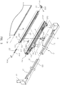
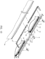
- a panel curtain according to the present invention includes an upper track 10, at least one rail set 20 and a plurality of panels 30.
- the upper track 10 consists of an inner track 11 and an outer track 12 and is telescopically adjustable in length.
- Two rail channels 13 are disposed on the inner track 11 and the outer track 12, respectively, located at the same side of the inner and the outer tracks 11, 12 and communicating with each other.
- Two snapping portions 111, 121 are disposed on the top of the inner track 11 and the top of the outer track 12, respectively.
- a plurality of clips 14 is arranged at the snapping portions 111, 121.
- the clip 14 consists of a locking portion 141 and an assembly portion 142 vertically extending from the front end thereof along a lateral surface of the upper track 10.
- the assembly portion 142 is formed in such a manner that two limiting channels 143 are arranged correspondingly on the upper and lower front side.
- Two touch fasteners 15 are fixed by the assembly portion 142 and a curtain fabric 16 is affixed to the touch fasteners 15.
- the rail set 20 is composed of a plurality of sliding rails 21 arranged in parallel.
- Each of the sliding rails 21 is provided with a positioning groove 211 and a limiting groove 212 that are disposed on two lateral surfaces thereof respectively and corresponding to each other while a panel groove 213 is arranged at the bottom of the respective sliding rail 21.
- a sliding block 22 is fixed on the distal end of the positioning groove 211 of the respective sliding rail 21 and is composed of a barrier piece 221 extending downward therefrom for covering one end of the panel groove 213 and two symmetrical limiting pieces 222 facing the limiting groove 212 of the adjacent sliding rail 21.
- Each of the sliding blocks 22 is slidably mounted and limited in the limiting groove 212 of the adjacent sliding rail 21.
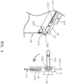
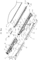
- a limiting block 23 with a buffer spring 231 is disposed on the front end of the limiting groove 212 of the respective sliding rail 21 and is provided with a bar 232 protruding therefrom to be outside the limiting groove 211 for pivotally connected with a swiveling stopper 233.
- a connecting rib 214 is disposed on the top of the respective sliding rail 21 and is provided with a plurality of punch holes in turn.
- a connecting sliding block 24 is mounted on the front end of the connecting rib 214 of the respective sliding rail 21 and is provided with a sliding locking portion 241 and a connecting portion 242. The length of the connecting portion 242 varies depending on the position of the respective sliding rail 21 among the sliding rails 21 in parallel.
- connecting sliding block 24 is fixed on the connecting rib 214 of the corresponding sliding rail 21 by the connecting portion 242 in such a manner that the sliding locking portions 241 are aligned and abut against one another.
- An insertion hole 243 is disposed on the connecting sliding block 24 at the position facing the opening of the rail channel 13 and used in combination with a linking piece 25 for connecting at least two connecting sliding blocks 24.
- the linked sliding rails 21 are moved together.
- the frontmost connecting sliding block 24 is disposed on the sliding rail 21 that is defined as the first one according to the sequential arrangement and is further provided with a cord binding portion 244 while a positioning block 26 is arranged at the distal end of the connecting rib 214 of the sliding rail 21.
- the positioning block 26 is provided with a sliding locking portion 261 slidably mounted into the rail channel 13 of the upper track 10 correspondingly.
- a packing piece 262 is disposed on the sliding locking portion 261 in such a manner that the packing piece is facing the opening of the rail channel 13.
- the packing piece 262 is used in combination with a fastener 263 and friction-locked by screwing the fastener 263.
- the positioning block 26 is further fixed and limited on the upper track 10.
- a panel holding portion 31 is formed on the top of the respective panel 30 and is slidably mounted in the panel groove 213 of the respective sliding rail 21 in such a manner that the panel holding portion is limited and positioned by the barrier piece 221 and the stopper 233 on two ends of the respective panel groove 213.
- a sliding block 22 is fixed on the distal end of the positioning groove 211 and a limiting block 23 is disposed on the front end of the limiting groove 212 in each of the sliding rails 21 of the rail set 20.
- the sliding rails 21 are arranged in parallel and the sliding block 22 is slid from the distal end of the positioning groove 211 into the limiting groove 212 of the adjacent sliding rail 21 so as to connect the sliding rails 21 in turn.
- a connecting sliding block 24 is mounted on the respective sliding rail 21 of the rail set 20.
- the connecting portions 242 of the connecting sliding blocks 24 are disposed on the front ends of the connecting ribs 214 above the sliding rails 21 respectively in turn according to the order of the sliding rails 21, allowing the sliding locking portions 241 of the connecting sliding blocks 24 to be arranged in parallel and aligned.
- the connecting sliding block 24 of the sliding rail 21 that is defined as the first one according to the sequential arrangement is further provided with a cord binding portion 244 while a positioning block 26 is mounted on the sliding rail 21 that is defined as the last one according to the sequential arrangement.
- the positioning block 26 is also provided with the sliding locking portion 261 that is aligned with the sliding locking portions 241 of the connecting sliding blocks 24.
- the sliding rails 21 are mounted into the rail channel 13 of the upper track 10 by the sliding locking portions 241 of the connecting sliding blocks 24 and the sliding locking portion 261 of the positioning block 26 and are thereby able to slide therein.
- the positioning block 26 is tightly attached to and positioned on the inner wall of the rail channel 13 by the packing piece 262 used in combination with the fastener 263 so as to prevent the sliding rail 21 that is defined as the last one according to the sequential arrangement from being pulled out.
- the sliding rail 21 that is defined as the last one according to the sequential arrangement is fixed by the positioning block 26.
- the upper track 10 is used in combination with a cord 17 for sliding and moving the rail set 20.
- the cord 17 is tied to the connecting sliding block 24 of the rail set 20 that is defined as the first connecting sliding block according to the sequential arrangement.
- a plurality of clips 14 is disposed on the upper track 10.
- the clips 14 are fixed on the snapping portions 111, 121 of the inner and the outer tracks 11, 12 respectively by means of the locking portions 141 while the two touch fasteners 15 are fixed on the limiting channels 143 of the assembly portion 142.
- the two touch fasteners 15 are fixed on the same clip 14 in a staggered manner and the length thereof is fine-adjustable along with telescopically adjusting the upper track 10.
- the curtain fabric 16 is provided for covering and decorating the upper track 10.
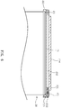
- the panel curtain of the present invention is arranged at a preset wall surface of windows or French windows with the upper track 10 for adjusting indoor lighting.
- the panels 30 are moved along with the sliding rails 21 of the rail set 20 and held together on one end of the upper track 10. Now the sliding rails 21 are arranged in parallel and the panels 30 are stacked in layers.
- the sliding rail 21 that is defined as the first one according to the sequential arrangement is drawn and moved along the rail channel 13 by pulling the cord 17.
- the sliding block 22 on the distal end of the positioning groove 211 is moved along the limiting groove 212 of another sliding rail 21 to abut against the limiting block 23 on the front end.
- the limiting block 23 is provided with the buffer spring 231 that is used for buffering force applied by the sliding rail 21 and the said another sliding rail 21 is also drawn and moved. Thereby the rest sliding rails 21 are slid out along the rail channel 13 one after another. Since the sliding rail 21 that is defined as the last one according to the sequential arrangement is firmly pressed onto and fixed on the upper track 10 by the positioning block 26, it will not be pulled out. Therefore the rail set 20 together with the panels 30 thereof is fully extended on the upper track 10 so that no light gets in.
- the upper track 10 consists of an inner track 11 and an outer track 12 assembled with each other so that the upper track 10 is telescopically adjustable in length.
- the number of the sliding rails 21 of the rail set 20 can be changed according to the length of the upper track 10.
- the linking piece 25 is provided with at least two pins 251 corresponding to the connecting sliding blocks 24. The two pins 251 are inserted into the insertion holes 243 of the two adjacent connecting sliding blocks 24 so that the two connecting sliding blocks 24 are drawn and slid synchronously.
- the two adjacent sliding rails 21 and the panels 30 thereof are pulled out at the same time.
- the area of the panel curtain extended is reduced, by one sliding rail 21 and one panel 30.
- the upper track 10 can be shortened and extended for blocking light. Or the upper track 10 in the original size is not fully extended/retracted for light control.
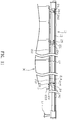
- the linking piece 25 is provided with three pins 251. Also refer to Fig. 11 , three sliding rails 21 and the panels 30 thereof of the rail set 20 are pulled out at the same time.
- the area of the panel curtain extended is reduced by two sliding rails 21 and two panels 30.
- the cord 17 is pulled in the opposite direction.
- the sliding rail 21 that is defined as the first one according to the sequential arrangement is moved back by sliding along the rail channel 13 of the upper track 10. While the mentioned sliding rail 21 is sliding in the opposite direction, the connecting sliding block 24 thereof is abutting against the connecting sliding block 24 of another sliding rail 21 (the adjacent one) so that the adjacent sliding rail 21 is pushed and drawn back. Thereby the sliding rails 21 are returned to the starting position in turn so that the panels 30 are moved to the side and stacked.
- the purpose of light control in the room is achieved.
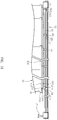
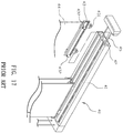
- FIG. 12-16 another embodiment is revealed. It is possible that two rail sets 20 are mounted in the upper track 10. When the two rail sets 20 are pushed together, they are located at the outermost ends of the inner track 11 and the outer track 12 respectively.
- the connecting sliding block 24 on the sliding rail 21 of the respective rail set 20 that is defined as the first sliding rail according to the sequential arrangement is provided with a cord binding portion 244 and tied with the cord 17.
- the sliding rail 21 that is defined as the last one according to the sequential arrangement is provided with a positioning block 26.
- the positioning block 26 is provided with a packing piece 262 and friction-locked on the upper track 10 by combining the packing piece 262 with a fastener 263.
- the coupling of the cord 17 enables the two rail sets 20 to move toward each other for closing the panel curtain or away from each other for opening the panel curtain while in use.
- the sliding rails 21 of the two rail sets 20 are not aligned and a gap is formed therebetween so that the two rail sets 20 are staggered to close the panel curtain when the sliding rails 21 that are defined as the first one according to the sequential arrangement are abutting against each other.
- a staggering spring 27 is arranged at the front end of the sliding rail 21 on the inner side for keeping the above two sliding rails 21 in the staggered state when the sliding sets 20 are staggered. Thereby the state of the two rail sets 20 in use is revealed.
- a connecting sliding block 24 is disposed on each of the sliding rails 21 of the respective rail set 20 and is provided with a connecting portion 242 whose length varies depending on the order of the sliding rail 21 among the sliding rails in parallel.
- the connecting portions 242 are used for allowing the sliding locking portions 241 to be aligned and mounted in the rail channel 13 of the upper track 10 after the connecting sliding blocks 24 and the sliding rails 21 being assembled. Thereby volume and size of the upper track are dramatically decreased and the packaging volume is effectively reduced.
- a sliding block 22 is fixed on the distal end of the positioning groove 211 of the respective sliding rail 21 and a barrier piece 221 is extending downward from the sliding block 22 for covering one end of the panel groove 213.
- a limiting block 23 is disposed on the front end of the limiting groove 212 and is provided with a swiveling stopper 233 for opening and closing the panel groove 213.
- the upper track 10 is used in combination with a plurality of clips 14 for mounting two touch fasteners 15 and a curtain fabric 16 is further arranged at the touch fasteners 15. While the panel curtain is installed and used, the upper track 10 thereof can be covered and decorated by the curtain fabric 16 for aesthetic purposes so as to enhance consumers' purchase intention.
Landscapes
- Engineering & Computer Science (AREA)
- Structural Engineering (AREA)
- Architecture (AREA)
- Civil Engineering (AREA)
- Curtains And Furnishings For Windows Or Doors (AREA)
Priority Applications (1)
| Application Number | Priority Date | Filing Date | Title |
|---|---|---|---|
| EP18214946.8A EP3670819B1 (fr) | 2018-12-20 | 2018-12-20 | Rideau de panneau |
Applications Claiming Priority (1)
| Application Number | Priority Date | Filing Date | Title |
|---|---|---|---|
| EP18214946.8A EP3670819B1 (fr) | 2018-12-20 | 2018-12-20 | Rideau de panneau |
Publications (3)
| Publication Number | Publication Date |
|---|---|
| EP3670819A1 true EP3670819A1 (fr) | 2020-06-24 |
| EP3670819C0 EP3670819C0 (fr) | 2023-07-19 |
| EP3670819B1 EP3670819B1 (fr) | 2023-07-19 |
Family
ID=64755318
Family Applications (1)
| Application Number | Title | Priority Date | Filing Date |
|---|---|---|---|
| EP18214946.8A Active EP3670819B1 (fr) | 2018-12-20 | 2018-12-20 | Rideau de panneau |
Country Status (1)
| Country | Link |
|---|---|
| EP (1) | EP3670819B1 (fr) |
Cited By (3)
| Publication number | Priority date | Publication date | Assignee | Title |
|---|---|---|---|---|
| CN114515096A (zh) * | 2022-01-26 | 2022-05-20 | 佛山市启沃智能窗饰有限公司 | 一种带有轨道对接器的电动窗帘轨道 |
| CN115263162A (zh) * | 2022-06-15 | 2022-11-01 | 中国建筑第八工程局有限公司 | 快装钢结构弧形膜百叶及其施工方法 |
| US20250172039A1 (en) * | 2023-11-29 | 2025-05-29 | Jin Daung Co., Ltd. | Light-adjustable shade |
Citations (4)
| Publication number | Priority date | Publication date | Assignee | Title |
|---|---|---|---|---|
| US5598880A (en) * | 1995-06-02 | 1997-02-04 | Burlington Industries, Inc. | Top treatment for blinds and packaging therefor |
| GB2431684A (en) * | 2005-10-21 | 2007-05-02 | Peter Anthony Manning | Extending top rail for sliding door |
| EP1859710A1 (fr) * | 2006-05-24 | 2007-11-28 | Chen-Ho Chu | Panneau coulissant |
| GB2442200A (en) * | 2006-09-29 | 2008-04-02 | Shan-Chi Chuang | Vertical blind |
-
2018
- 2018-12-20 EP EP18214946.8A patent/EP3670819B1/fr active Active
Patent Citations (4)
| Publication number | Priority date | Publication date | Assignee | Title |
|---|---|---|---|---|
| US5598880A (en) * | 1995-06-02 | 1997-02-04 | Burlington Industries, Inc. | Top treatment for blinds and packaging therefor |
| GB2431684A (en) * | 2005-10-21 | 2007-05-02 | Peter Anthony Manning | Extending top rail for sliding door |
| EP1859710A1 (fr) * | 2006-05-24 | 2007-11-28 | Chen-Ho Chu | Panneau coulissant |
| GB2442200A (en) * | 2006-09-29 | 2008-04-02 | Shan-Chi Chuang | Vertical blind |
Cited By (5)
| Publication number | Priority date | Publication date | Assignee | Title |
|---|---|---|---|---|
| CN114515096A (zh) * | 2022-01-26 | 2022-05-20 | 佛山市启沃智能窗饰有限公司 | 一种带有轨道对接器的电动窗帘轨道 |
| CN115263162A (zh) * | 2022-06-15 | 2022-11-01 | 中国建筑第八工程局有限公司 | 快装钢结构弧形膜百叶及其施工方法 |
| CN115263162B (zh) * | 2022-06-15 | 2024-06-14 | 中国建筑第八工程局有限公司 | 快装钢结构弧形膜百叶及其施工方法 |
| US20250172039A1 (en) * | 2023-11-29 | 2025-05-29 | Jin Daung Co., Ltd. | Light-adjustable shade |
| US12584350B2 (en) * | 2023-11-29 | 2026-03-24 | Jin Daung Co., Ltd. | Light-adjustable shade |
Also Published As
| Publication number | Publication date |
|---|---|
| EP3670819C0 (fr) | 2023-07-19 |
| EP3670819B1 (fr) | 2023-07-19 |
Similar Documents
| Publication | Publication Date | Title |
|---|---|---|
| EP3670819B1 (fr) | Rideau de panneau | |
| US11242712B2 (en) | Vertical blinds | |
| US2729287A (en) | Shutter, window, or the like | |
| AU2011201002B2 (en) | Single-track stacking panel covering for an architectural opening | |
| US20160235237A1 (en) | Magnetic curtain and sliding panel formed therefrom | |
| US9316050B2 (en) | Cordless curtain assembly | |
| US20220275682A1 (en) | Hanging blinds | |
| US20110005690A1 (en) | Window Covering | |
| US20070261799A1 (en) | Sliding panel | |
| US11060346B2 (en) | Window curtain | |
| US20160376839A1 (en) | Cord-winding Device for a Window Blind Capable of Rapidly Winding and Unwinding a Cord | |
| CA2602488C (fr) | Couvre-fenetre cintre | |
| CN107484365B (zh) | 一种伸缩式底盒 | |
| JP3220935U (ja) | ブラインド構造 | |
| US10584530B2 (en) | Transmission device for cordless window shades | |
| JPS628165B2 (fr) | ||
| US10689903B2 (en) | Single-track stacking panel covering for an architectural opening | |
| AU2020100109A4 (en) | Window Curtain | |
| CN109339682B (zh) | 一种窗帘装置 | |
| EP4088626A1 (fr) | Rideaux suspendus | |
| CN209031819U (zh) | 片帘的结构 | |
| TWM579506U (zh) | 片簾之結構(一) | |
| CN109199056B (zh) | 一种窗帘装置 | |
| CN201032998Y (zh) | 推拉式通风吊帘机构及其吊帘 | |
| TW201237256A (en) | Sunshade with immediate pull-to-stop function |
Legal Events
| Date | Code | Title | Description |
|---|---|---|---|
| PUAI | Public reference made under article 153(3) epc to a published international application that has entered the european phase |
Free format text: ORIGINAL CODE: 0009012 |
|
| STAA | Information on the status of an ep patent application or granted ep patent |
Free format text: STATUS: THE APPLICATION HAS BEEN PUBLISHED |
|
| AK | Designated contracting states |
Kind code of ref document: A1 Designated state(s): AL AT BE BG CH CY CZ DE DK EE ES FI FR GB GR HR HU IE IS IT LI LT LU LV MC MK MT NL NO PL PT RO RS SE SI SK SM TR |
|
| AX | Request for extension of the european patent |
Extension state: BA ME |
|
| STAA | Information on the status of an ep patent application or granted ep patent |
Free format text: STATUS: REQUEST FOR EXAMINATION WAS MADE |
|
| 17P | Request for examination filed |
Effective date: 20201216 |
|
| RBV | Designated contracting states (corrected) |
Designated state(s): AL AT BE BG CH CY CZ DE DK EE ES FI FR GB GR HR HU IE IS IT LI LT LU LV MC MK MT NL NO PL PT RO RS SE SI SK SM TR |
|
| STAA | Information on the status of an ep patent application or granted ep patent |
Free format text: STATUS: EXAMINATION IS IN PROGRESS |
|
| 17Q | First examination report despatched |
Effective date: 20220126 |
|
| GRAP | Despatch of communication of intention to grant a patent |
Free format text: ORIGINAL CODE: EPIDOSNIGR1 |
|
| STAA | Information on the status of an ep patent application or granted ep patent |
Free format text: STATUS: GRANT OF PATENT IS INTENDED |
|
| INTG | Intention to grant announced |
Effective date: 20230130 |
|
| GRAS | Grant fee paid |
Free format text: ORIGINAL CODE: EPIDOSNIGR3 |
|
| GRAA | (expected) grant |
Free format text: ORIGINAL CODE: 0009210 |
|
| STAA | Information on the status of an ep patent application or granted ep patent |
Free format text: STATUS: THE PATENT HAS BEEN GRANTED |
|
| RIN1 | Information on inventor provided before grant (corrected) |
Inventor name: CHUANG, SHAN-CHI |
|
| AK | Designated contracting states |
Kind code of ref document: B1 Designated state(s): AL AT BE BG CH CY CZ DE DK EE ES FI FR GB GR HR HU IE IS IT LI LT LU LV MC MK MT NL NO PL PT RO RS SE SI SK SM TR |
|
| REG | Reference to a national code |
Ref country code: GB Ref legal event code: FG4D |
|
| REG | Reference to a national code |
Ref country code: CH Ref legal event code: EP |
|
| REG | Reference to a national code |
Ref country code: DE Ref legal event code: R096 Ref document number: 602018053540 Country of ref document: DE |
|
| REG | Reference to a national code |
Ref country code: IE Ref legal event code: FG4D |
|
| U01 | Request for unitary effect filed |
Effective date: 20230811 |
|
| U07 | Unitary effect registered |
Designated state(s): AT BE BG DE DK EE FI FR IT LT LU LV MT NL PT SE SI Effective date: 20230818 |
|
| REG | Reference to a national code |
Ref country code: LT Ref legal event code: MG9D |
|
| PG25 | Lapsed in a contracting state [announced via postgrant information from national office to epo] |
Ref country code: GR Free format text: LAPSE BECAUSE OF FAILURE TO SUBMIT A TRANSLATION OF THE DESCRIPTION OR TO PAY THE FEE WITHIN THE PRESCRIBED TIME-LIMIT Effective date: 20231020 |
|
| PG25 | Lapsed in a contracting state [announced via postgrant information from national office to epo] |
Ref country code: IS Free format text: LAPSE BECAUSE OF FAILURE TO SUBMIT A TRANSLATION OF THE DESCRIPTION OR TO PAY THE FEE WITHIN THE PRESCRIBED TIME-LIMIT Effective date: 20231119 |
|
| PG25 | Lapsed in a contracting state [announced via postgrant information from national office to epo] |
Ref country code: RS Free format text: LAPSE BECAUSE OF FAILURE TO SUBMIT A TRANSLATION OF THE DESCRIPTION OR TO PAY THE FEE WITHIN THE PRESCRIBED TIME-LIMIT Effective date: 20230719 Ref country code: NO Free format text: LAPSE BECAUSE OF FAILURE TO SUBMIT A TRANSLATION OF THE DESCRIPTION OR TO PAY THE FEE WITHIN THE PRESCRIBED TIME-LIMIT Effective date: 20231019 Ref country code: IS Free format text: LAPSE BECAUSE OF FAILURE TO SUBMIT A TRANSLATION OF THE DESCRIPTION OR TO PAY THE FEE WITHIN THE PRESCRIBED TIME-LIMIT Effective date: 20231119 Ref country code: HR Free format text: LAPSE BECAUSE OF FAILURE TO SUBMIT A TRANSLATION OF THE DESCRIPTION OR TO PAY THE FEE WITHIN THE PRESCRIBED TIME-LIMIT Effective date: 20230719 Ref country code: GR Free format text: LAPSE BECAUSE OF FAILURE TO SUBMIT A TRANSLATION OF THE DESCRIPTION OR TO PAY THE FEE WITHIN THE PRESCRIBED TIME-LIMIT Effective date: 20231020 |
|
| U20 | Renewal fee for the european patent with unitary effect paid |
Year of fee payment: 6 Effective date: 20231222 |
|
| PG25 | Lapsed in a contracting state [announced via postgrant information from national office to epo] |
Ref country code: PL Free format text: LAPSE BECAUSE OF FAILURE TO SUBMIT A TRANSLATION OF THE DESCRIPTION OR TO PAY THE FEE WITHIN THE PRESCRIBED TIME-LIMIT Effective date: 20230719 |
|
| REG | Reference to a national code |
Ref country code: DE Ref legal event code: R097 Ref document number: 602018053540 Country of ref document: DE |
|
| PG25 | Lapsed in a contracting state [announced via postgrant information from national office to epo] |
Ref country code: ES Free format text: LAPSE BECAUSE OF FAILURE TO SUBMIT A TRANSLATION OF THE DESCRIPTION OR TO PAY THE FEE WITHIN THE PRESCRIBED TIME-LIMIT Effective date: 20230719 |
|
| PG25 | Lapsed in a contracting state [announced via postgrant information from national office to epo] |
Ref country code: SM Free format text: LAPSE BECAUSE OF FAILURE TO SUBMIT A TRANSLATION OF THE DESCRIPTION OR TO PAY THE FEE WITHIN THE PRESCRIBED TIME-LIMIT Effective date: 20230719 Ref country code: RO Free format text: LAPSE BECAUSE OF FAILURE TO SUBMIT A TRANSLATION OF THE DESCRIPTION OR TO PAY THE FEE WITHIN THE PRESCRIBED TIME-LIMIT Effective date: 20230719 Ref country code: ES Free format text: LAPSE BECAUSE OF FAILURE TO SUBMIT A TRANSLATION OF THE DESCRIPTION OR TO PAY THE FEE WITHIN THE PRESCRIBED TIME-LIMIT Effective date: 20230719 Ref country code: CZ Free format text: LAPSE BECAUSE OF FAILURE TO SUBMIT A TRANSLATION OF THE DESCRIPTION OR TO PAY THE FEE WITHIN THE PRESCRIBED TIME-LIMIT Effective date: 20230719 Ref country code: SK Free format text: LAPSE BECAUSE OF FAILURE TO SUBMIT A TRANSLATION OF THE DESCRIPTION OR TO PAY THE FEE WITHIN THE PRESCRIBED TIME-LIMIT Effective date: 20230719 |
|
| PLBE | No opposition filed within time limit |
Free format text: ORIGINAL CODE: 0009261 |
|
| STAA | Information on the status of an ep patent application or granted ep patent |
Free format text: STATUS: NO OPPOSITION FILED WITHIN TIME LIMIT |
|
| 26N | No opposition filed |
Effective date: 20240422 |
|
| REG | Reference to a national code |
Ref country code: CH Ref legal event code: PL |
|
| PG25 | Lapsed in a contracting state [announced via postgrant information from national office to epo] |
Ref country code: MC Free format text: LAPSE BECAUSE OF FAILURE TO SUBMIT A TRANSLATION OF THE DESCRIPTION OR TO PAY THE FEE WITHIN THE PRESCRIBED TIME-LIMIT Effective date: 20230719 |
|
| PG25 | Lapsed in a contracting state [announced via postgrant information from national office to epo] |
Ref country code: MC Free format text: LAPSE BECAUSE OF FAILURE TO SUBMIT A TRANSLATION OF THE DESCRIPTION OR TO PAY THE FEE WITHIN THE PRESCRIBED TIME-LIMIT Effective date: 20230719 |
|
| REG | Reference to a national code |
Ref country code: IE Ref legal event code: MM4A |
|
| PG25 | Lapsed in a contracting state [announced via postgrant information from national office to epo] |
Ref country code: IE Free format text: LAPSE BECAUSE OF NON-PAYMENT OF DUE FEES Effective date: 20231220 |
|
| PG25 | Lapsed in a contracting state [announced via postgrant information from national office to epo] |
Ref country code: CH Free format text: LAPSE BECAUSE OF NON-PAYMENT OF DUE FEES Effective date: 20231231 |
|
| PG25 | Lapsed in a contracting state [announced via postgrant information from national office to epo] |
Ref country code: IE Free format text: LAPSE BECAUSE OF NON-PAYMENT OF DUE FEES Effective date: 20231220 Ref country code: CH Free format text: LAPSE BECAUSE OF NON-PAYMENT OF DUE FEES Effective date: 20231231 |
|
| PGFP | Annual fee paid to national office [announced via postgrant information from national office to epo] |
Ref country code: GB Payment date: 20241230 Year of fee payment: 7 |
|
| U20 | Renewal fee for the european patent with unitary effect paid |
Year of fee payment: 7 Effective date: 20241227 |
|
| PG25 | Lapsed in a contracting state [announced via postgrant information from national office to epo] |
Ref country code: CY Free format text: LAPSE BECAUSE OF FAILURE TO SUBMIT A TRANSLATION OF THE DESCRIPTION OR TO PAY THE FEE WITHIN THE PRESCRIBED TIME-LIMIT; INVALID AB INITIO Effective date: 20181220 |
|
| PG25 | Lapsed in a contracting state [announced via postgrant information from national office to epo] |
Ref country code: HU Free format text: LAPSE BECAUSE OF FAILURE TO SUBMIT A TRANSLATION OF THE DESCRIPTION OR TO PAY THE FEE WITHIN THE PRESCRIBED TIME-LIMIT; INVALID AB INITIO Effective date: 20181220 |
|
| PG25 | Lapsed in a contracting state [announced via postgrant information from national office to epo] |
Ref country code: TR Free format text: LAPSE BECAUSE OF FAILURE TO SUBMIT A TRANSLATION OF THE DESCRIPTION OR TO PAY THE FEE WITHIN THE PRESCRIBED TIME-LIMIT Effective date: 20230719 |