EP3670825B1 - Autonomer verbindungsaufbau und auswertung - Google Patents
Autonomer verbindungsaufbau und auswertung Download PDFInfo
- Publication number
- EP3670825B1 EP3670825B1 EP19217379.7A EP19217379A EP3670825B1 EP 3670825 B1 EP3670825 B1 EP 3670825B1 EP 19217379 A EP19217379 A EP 19217379A EP 3670825 B1 EP3670825 B1 EP 3670825B1
- Authority
- EP
- European Patent Office
- Prior art keywords
- tubular
- turns
- measurements
- tong
- torque
- Prior art date
- Legal status (The legal status is an assumption and is not a legal conclusion. Google has not performed a legal analysis and makes no representation as to the accuracy of the status listed.)
- Active
Links
Images


Classifications
-
- E—FIXED CONSTRUCTIONS
- E21—EARTH OR ROCK DRILLING; MINING
- E21B—EARTH OR ROCK DRILLING; OBTAINING OIL, GAS, WATER, SOLUBLE OR MELTABLE MATERIALS OR A SLURRY OF MINERALS FROM WELLS
- E21B19/00—Handling rods, casings, tubes or the like outside the borehole, e.g. in the derrick; Apparatus for feeding the rods or cables
- E21B19/16—Connecting or disconnecting pipe couplings or joints
- E21B19/165—Control or monitoring arrangements therefor
-
- E—FIXED CONSTRUCTIONS
- E21—EARTH OR ROCK DRILLING; MINING
- E21B—EARTH OR ROCK DRILLING; OBTAINING OIL, GAS, WATER, SOLUBLE OR MELTABLE MATERIALS OR A SLURRY OF MINERALS FROM WELLS
- E21B19/00—Handling rods, casings, tubes or the like outside the borehole, e.g. in the derrick; Apparatus for feeding the rods or cables
- E21B19/16—Connecting or disconnecting pipe couplings or joints
- E21B19/165—Control or monitoring arrangements therefor
- E21B19/166—Arrangements of torque limiters or torque indicators
-
- E—FIXED CONSTRUCTIONS
- E21—EARTH OR ROCK DRILLING; MINING
- E21B—EARTH OR ROCK DRILLING; OBTAINING OIL, GAS, WATER, SOLUBLE OR MELTABLE MATERIALS OR A SLURRY OF MINERALS FROM WELLS
- E21B17/00—Drilling rods or pipes; Flexible drill strings; Kellies; Drill collars; Sucker rods; Cables; Casings; Tubings
- E21B17/02—Couplings; joints
- E21B17/04—Couplings; joints between rod or the like and bit or between rod and rod or the like
- E21B17/042—Threaded
-
- E—FIXED CONSTRUCTIONS
- E21—EARTH OR ROCK DRILLING; MINING
- E21B—EARTH OR ROCK DRILLING; OBTAINING OIL, GAS, WATER, SOLUBLE OR MELTABLE MATERIALS OR A SLURRY OF MINERALS FROM WELLS
- E21B19/00—Handling rods, casings, tubes or the like outside the borehole, e.g. in the derrick; Apparatus for feeding the rods or cables
- E21B19/10—Slips; Spiders ; Catching devices
-
- E—FIXED CONSTRUCTIONS
- E21—EARTH OR ROCK DRILLING; MINING
- E21B—EARTH OR ROCK DRILLING; OBTAINING OIL, GAS, WATER, SOLUBLE OR MELTABLE MATERIALS OR A SLURRY OF MINERALS FROM WELLS
- E21B19/00—Handling rods, casings, tubes or the like outside the borehole, e.g. in the derrick; Apparatus for feeding the rods or cables
- E21B19/16—Connecting or disconnecting pipe couplings or joints
-
- E—FIXED CONSTRUCTIONS
- E21—EARTH OR ROCK DRILLING; MINING
- E21B—EARTH OR ROCK DRILLING; OBTAINING OIL, GAS, WATER, SOLUBLE OR MELTABLE MATERIALS OR A SLURRY OF MINERALS FROM WELLS
- E21B45/00—Measuring the drilling time or rate of penetration
-
- F—MECHANICAL ENGINEERING; LIGHTING; HEATING; WEAPONS; BLASTING
- F16—ENGINEERING ELEMENTS AND UNITS; GENERAL MEASURES FOR PRODUCING AND MAINTAINING EFFECTIVE FUNCTIONING OF MACHINES OR INSTALLATIONS; THERMAL INSULATION IN GENERAL
- F16H—GEARING
- F16H59/00—Control inputs to control units of change-speed- or reversing-gearings for conveying rotary motion
- F16H59/14—Inputs being a function of torque or torque demand
- F16H59/141—Inputs being a function of torque or torque demand of rate of change of torque or torque demand
-
- F—MECHANICAL ENGINEERING; LIGHTING; HEATING; WEAPONS; BLASTING
- F16—ENGINEERING ELEMENTS AND UNITS; GENERAL MEASURES FOR PRODUCING AND MAINTAINING EFFECTIVE FUNCTIONING OF MACHINES OR INSTALLATIONS; THERMAL INSULATION IN GENERAL
- F16L—PIPES; JOINTS OR FITTINGS FOR PIPES; SUPPORTS FOR PIPES, CABLES OR PROTECTIVE TUBING; MEANS FOR THERMAL INSULATION IN GENERAL
- F16L15/00—Screw-threaded joints; Forms of screw-threads for such joints
- F16L15/02—Screw-threaded joints; Forms of screw-threads for such joints allowing substantial longitudinal adjustment by the use of a long screw-threaded part
-
- G—PHYSICS
- G01—MEASURING; TESTING
- G01L—MEASURING FORCE, STRESS, TORQUE, WORK, MECHANICAL POWER, MECHANICAL EFFICIENCY, OR FLUID PRESSURE
- G01L5/00—Apparatus for, or methods of, measuring force, work, mechanical power, or torque, specially adapted for specific purposes
- G01L5/24—Apparatus for, or methods of, measuring force, work, mechanical power, or torque, specially adapted for specific purposes for determining value of torque or twisting moment for tightening a nut or other member which is similarly stressed
Definitions
- a tong assembly is commonly used to make up or break out joints in the tubular strings.
- a tong assembly may be manually controlled by an operator during makeup.
- a dump valve is usually used to stop the rotation when at a target torque.
- this manual control may lead to over torque, for example, when the rotational speed of the tong assembly is too high at a final stage of joint make up.
- Another approach to achieve the target torque is using a closed-loop control of torque or rotational speed during makeup. However, depending on the set speed, the closed-loop control method takes a long time to makeup each joint.
- Another approach to achieve the target torque is to rotate the tong assembly for a predetermined time at a constant speed. The predetermined time is obtained from heuristically measured values, which are results of particular parameters, such as the reactions time of the tong assembly to a specific type of tubulars and the speed of the tong assembly.
- the system includes a tong assembly comprising a power tong for clamping to a first tubular and rotating the first tubular, and a backup tong for clamping to a second tubular and holding the second tubular stationary, and a controller including instructions, which when executed, perform operations comprising making up a threaded connection using the tong assembly while measuring one or more parameters, wherein the one or more parameters include at least one of torque applied to the threaded connection, turns of the first tubular, or combination thereof, correcting measurements of the one or more parameters to remove effects due to mechanical properties and dynamic behavior of the tong assembly, and evaluating the threaded connection using corrected measurements of the one or more parameters.
- the method includes rotating a first tubular relative to a second tubular at a first speed to make a threaded connection between the first and second tubulars using a tong assembly while measuring one or more parameters, wherein the one or more parameters includes at least one of torque applied to the threaded connection, turns of the first tubular, or combination thereof, recording one or more operating parameters of the tong assembly, evaluating the one or more operating parameters and measurements of the one or more parameters for a marker, and accepting or rejecting the threaded connection based on the evaluation.
- FIG. 1A illustrates a connection 1 between premium grade tubulars 2, 4.
- the tubulars 2, 4 may be any oil industry tubular good, such as production tubing, casing, liner, or drill pipe.
- the connection 1 may include a first tubular 2 joined to a second tubular 4 through a tubular coupling 6.
- Each of the tubulars 2, 4 and the coupling 6 may be made from a metal or alloy, such as plain carbon steel, low alloy steel, high strength low alloy steel, stainless steel, or a nickel based alloy.
- the end of each tubular 2, 4 may have a tapered externally-threaded surface 8 (aka a pin) which co-operates with a correspondingly tapered internally-threaded surface (aka box) 10 on the coupling 6.
- the power tong 206 receives and clamps to a first tubular, such as the tubular 2, while the backup tong 208 receives and clamps to a second tubular, such as a tubular 44 on top of the work string 212.
- the tubular 44 may include a coupling 6 that is pre-made on the tubular 44.
- the backup tong 208 clamps to the tubular 4 below the coupling 66.
- the power tong 206 rotates the first tubular while the backup tong 208 holds the second tubular stationary causing relative rotation between the first tubular and second tubular, thus, making up a threaded connection between the first and second tubulars or breaking out the threaded connection between the first and second tubulars.
- the power tong 206 and the backup tong 208 may be coupled together by a frame 218.
- the power tong 206 may include a side door 220 which may open to receive or release a tubular and close to clamp the tubular in the power tong 206.
- the backup tong 208 may include a side door 222 which may open to receive or release a tubular and close to clamp the tubular in the backup tong 208.
- One or more actuators 232 may be used to drive gripping pads in the power tong 206 to clamp a tubular during operation.
- One or more actuators 230 may be used to drive gripping pads in the backup tong 208 to clamp a tubular and hold the tubular stationary during operation.
- the actuators 230, 232 may be hydraulic actuators, mechanical actuators, or other suitable actuators.
- the actuators 230, 232 are connected to the controller 204 and may receive commands from the controller 204 to clamp a tubular, release a tubular, or adjust clamping force exerted against a tubular.
- the controller 204 may be connected to other actuators, such as the actuators 230, 232, through a drive unit, such as a hydraulic power unit when the actuators are hydraulic actuators.
- the power tong 206 may include a drive unit 229 configured to drive a motor assembly 224.
- the motor assembly 224 is configured to rotate the tubular clamped in the power tong 206.
- the drive unit 229 may be a hydraulic drive circuit configured to drive a hydraulic motor.
- the motor assembly 224 may include a drive motor and a gear assembly.
- the motor assembly 224 may include a hydraulic motor assembly or an electric motor assembly.
- the motor assembly 224 and the drive unit 229 are connected to the controller 204.
- the motor assembly 224 may receive commands from the controller 204 to rotate forward, backward, and at a target speed.
- the tong assembly 202 may include a turns counter 228.
- the turns counter 228 may be connected to the controller 204 to monitor the rotation of the power tong 206.
- the turns counter 228 may be an internal turns counter such as a decoder connected to a drive shaft inside a gear box of the power tong 206.
- the turns counter 228 is connected to the controller 204 and can be used to measure turns of the tubular clamped in the power tong 206 during operation.
- Figure 3B schematically illustrates connections among the tong assembly 202, the automated makeup module 302 and the automated evaluation module 304.
- the automated makeup module 302 sends out commands to the actuators 230, 232 to clamping and clamping forces in the backup tong 208 and the power tong 206 via connections 318, 322 respectively.
- a first branch 318a, 322a of the connection 318, 322 goes to the actuators 230, 232 to control clamping and release of tubulars in the tong assembly 202 during operation.
- a second branch 318b, 322b of the connection 318, 322 goes to the automated evaluation module 304, wherein data related to clamping operation is recorded and used for evaluation of the connection being made.
- Measurements of the turns counter 228 may be sent to the automated makeup module 302 and the automated evaluation module 304 through connection 326-326a and 326-326b respectively. During operation, the measurements of the turns counter 228 may be sent to the automated makeup module 302 and the automated evaluation module 304 in synchronization or at different frequency and/or for different time periods according to the process design. Measurements of the turns counter 228 may be used to determine turns made by the motor to the threaded connection and used for controlling the makeup process and as basis for evaluating the threaded connection.
- the automated evaluation module 304 is configured to automatically evaluate a threaded connection based on process parameters and sensor measurements made during makeup. After a threaded connection is made using the automated makeup module 302, the threaded connection can be evaluated by the automated evaluation module 304 for a decision whether the threaded connection is acceptable or should be rejected and remake.
- One or a combination of measurements made during makeup may be corrected by the measurement corrector 340 before being used to evaluate the threaded connection by the connection evaluator 344.
- the measurement corrector 340 may correlate the torque measurements, turn measurements, and time measurements with operating information received from the automated makeup module 302.
- the measurement corrector 340 may include a displacement correction.
- Flexible deformation of the tong structure occurs during operations, such as when the tong assembly carries the load of torque and/or weight, when the tong clamps at the tubular, and when the clamping force is changed. For example, an increased clamping force will drive protrusions on the gripping pads deeper into the tubular being clamped resulting in additional turns of the tong assembly while the tubulars clamped in the tong assembly stay stationary.
- the flexible deformation sometime results in additional turns measured in the turns sensors coupled to the tong assembly, such as the turns counter 228.
- the additional turns captured by the internal turns counters, such as the turns counter 228, do not reflect the actual turns of the tubulars.
- Turns measurement such as measurements from the turns counter 228, may be corrected according to commands of clamping, such as commands received from the automated makeup module 302 via connections 318-318b and 322-322b.
- the automated evaluation module 304 increases accuracy of the automated evaluation.
- Automated evaluation based on measurements only has a higher reject rate than evaluation by human operators. Connections that are acceptable by a human operator are sometime rejected because false failure patterns that result from dynamic behaviors and mechanical properties of the tong assembly as well as incorrect turns data.
- Automated evaluation according to the present disclosure improves traceability of decisions by a human and allows for more detailed evaluation without sacrificing measurement resolution by applying filters. Instead of reducing sensitivity of the evaluation using filters, the automated evaluation methods according to the present disclosure removes known issues from the evaluation, therefore allowing a higher resolution on the data.
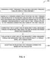
- Figure 4 is a flow chart of a method 400 for making up and evaluating a tubular connection evaluator.
- the method 400 may be performed by the tubular makeup and evaluation system 200 described above.
- a first threaded tubular, such as the tubular 2, and a second threaded tubular, such as the tubular 4 and coupling 6, are engaged using a tong assembly, such as the tong assembly 202.
- the engagement of the threaded tubulars may be in the condition as shown in Figure 1A .
- the method may further include measuring the turns of the second tubular using a turns sensor attached to the backup tong, and wherein correcting measurements of the one or more parameters comprises: correcting measurements of turns of the first tubular according to turns of the second tubular.
- the method may further include correcting measurement of torque made during deceleration of the tong assembly.
- Correcting measurements of the one or more parameters may comprise: correcting measurements of turns of the first tubular according to clamping commands or change of clamping force.
- the method may further include reducing measurements of turns when clamping force is increased.
- the system may further include a turns counter positioned to measure turns of the second tubular relative to the backup tong, wherein the instructions further comprise correcting measurements of turns of the first tubular according to measured turns of the second tubular.
- a method of making up a tubular joint includes rotating a first tubular relative to a second tubular at a first speed to make a threaded connection between the first and second tubulars using a tong assembly while measuring one or more parameters, wherein the one or more parameters includes at least one of torque applied to the threaded connection, turns of the first tubular, or combination thereof, recording one or more operating parameters of the tong assembly, evaluating the one or more operating parameters and measurements of the one or more parameters for a marker, and accepting or rejecting the threaded connection based on the evaluation.
- the method may further include measuring turns of the second tubular, and correcting measured turns of the first tubular according to measured turns of the second tubular.
- Rotating the first tubular relative to the second tubular may comprise starting an automatic speed reduction operation to reduce rotating speed to zero upon detection of a trigger condition based on measurements of the one or more parameters.
- the marker may include at least one of a discontinuity, a torque spike, and a torque drop in a torque-turn curve.
Landscapes
- Engineering & Computer Science (AREA)
- Geology (AREA)
- Life Sciences & Earth Sciences (AREA)
- Mining & Mineral Resources (AREA)
- Physics & Mathematics (AREA)
- Environmental & Geological Engineering (AREA)
- Fluid Mechanics (AREA)
- General Life Sciences & Earth Sciences (AREA)
- Geochemistry & Mineralogy (AREA)
- Mechanical Engineering (AREA)
- Force Measurement Appropriate To Specific Purposes (AREA)
- Investigating Strength Of Materials By Application Of Mechanical Stress (AREA)
- Non-Disconnectible Joints And Screw-Threaded Joints (AREA)
Claims (13)
- Verfahren zum Zusammensetzen einer Rohrverbindung, das Folgendes umfasst:Drehen eines ersten Rohrelements (2) relativ zu einem zweiten Rohrelement (4), um eine Gewindeverbindung zwischen dem ersten und dem zweiten Rohrelement unter Verwendung einer Zangenanordnung (202) während des Messens eines auf die Gewindeverbindung ausgeübten Drehmoments und während des Messens von Drehungen des ersten Rohrelements (2) relativ zum zweiten Rohrelement (4) herzustellen;Korrigieren von Messwerten des Drehmoments während eines Drehens der Zangenanordnung, wie zum Ausgleichen von dynamischem Verhalten und mechanischen Eigenschaften der Zangenanordnung (202) erforderlich;Korrigieren von Messwerten der Drehungen während eines Drehens der Zangenanordnung, wie zum Ausgleichen inkorrekter Drehungsdaten erforderlich;Bewerten der korrigierten Messwerte des Drehmoments und der korrigierten Messwerte der Drehungen; undFeststellen, ob die Gewindeverbindung akzeptabel ist, auf der Basis der Bewertung der korrigierten Messwerte.
- Verfahren nach Anspruch 1, das ferner Folgendes umfasst:
Bewerten der korrigierten Messwerte der Drehungen und der korrigierten Messwerte des Drehmoments, um mindestens eines von einer Diskontinuität, einer Spitze und einem Abfall zu identifizieren. - Verfahren nach Anspruch 1 oder 2, wobei während eines Drehens das erste Rohrelement (2) durch eine Kraftzange (206) in der Zangenanordnung (202) gedreht wird und das zweite Rohrelement (4) durch eine Sicherungszange (208) der Zangenanordnung eingeklemmt wird.
- Verfahren nach Anspruch 3, das ferner das Messen von Drehungen des zweiten Rohrelements (4) unter Verwendung eines an der Sicherungszange (208) angebrachten Drehungssensors (236), und das Korrigieren der Messwerte der Drehungen des ersten Rohrelements (2) auf der Basis der Drehungen des zweiten Rohrelements umfasst.
- Verfahren nach einem vorhergehenden Anspruch, das ferner Folgendes umfasst: Korrigieren der Messwerte der Drehungen des ersten Rohrelements (2) auf der Basis von mindestens einem von Klemmbefehlen und einer Klemmkraftänderung.
- Verfahren nach Anspruch 5, wobei das Verfahren ferner das Reduzieren der Messwerte der Drehungen umfasst, wenn eine Klemmkraft erhöht wird.
- Verfahren nach einem vorhergehenden Anspruch, das ferner Folgendes umfasst:Aufzeichnen eines oder mehrerer Betriebsparameter der Zangenanordnung (202); undBewerten des einen oder der mehreren Betriebsparameter, um einen Verzögerungsbefehl für die Zangenanordnung zu identifizieren.
- Verfahren nach Anspruch 1, das ferner Folgendes umfasst:
Starten einer automatischen Geschwindigkeitsreduzierungsoperation zum Reduzieren einer Drehgeschwindigkeit auf Null, wenn eine Auslösebedingung auf der Basis der Messwerte des auf die Gewindeverbindung ausgeübten Drehmoments erfasst wird. - Verfahren nach Anspruch 7, das ferner Folgendes umfasst:Bewerten des einen oder der mehreren Betriebsparameter, um das dynamische Verhalten und mechanische Eigenschaften der Zangenanordnung (202) zu identifizieren; undEntfernen von durch das dynamische Verhalten und mechanische Eigenschaften der Zangenanordnung verursachten Effekten aus einer Drehmoment-Drehungs-Kurve.
- Rohrelementzusammensetzsystem, das Folgendes umfasst:
eine Zangenanordnung (202), die Folgendes umfasst:eine Kraftzange (206), die zum Drehen eines ersten Rohrelements angepasst ist; undeine Sicherungszange (208), die zum Festklemmen eines zweiten Rohrelements angepasst ist; undeine Steuerung (204), die Befehle einschließt, die bei Ausführung Operationen durchführen, die Folgendes umfassen:Herstellen einer Gewindeverbindung des ersten Rohrelements (2) mit dem zweiten Rohrelement (4) unter Verwendung der Zangenanordnung während des Messens eines auf die Gewindeverbindung ausgeübten Drehmoments und während des Messens von Drehungen des ersten Rohrelements (2) relativ zum zweiten Rohrelement (4);Korrigieren von Messwerten des Drehmoments während eines Drehens der Zangenanordnung, wie zum Ausgleichen von dynamischem Verhalten und mechanischen Eigenschaften der Zangenanordnung (202) erforderlich;Korrigieren von Messwerten der Drehungen während eines Drehens der Zangenanordnung (202), wie zum Ausgleichen inkorrekter Drehungsdaten erforderlich;Bewerten der korrigierten Messwerte des Drehmoments und der korrigierten Messwerte der Drehungen;
undFeststellen, ob die Gewindeverbindung akzeptabel ist, auf der Basis der Bewertung der korrigierten Messwerte. - Rohrelementzusammensetzsystem nach Anspruch 10, wobei die Befehle ferner Folgendes umfassen:Aufzeichnen eines oder mehrerer Betriebsparameter während des Herstellens der Gewindeverbindung; undKorrigieren von Messwerten des Drehmoments, um durch den einen oder die mehreren aufgezeichneten Betriebsparameter verursachte Effekte zu beseitigen.
- Rohrelementzusammensetzsystem nach Anspruch 11, das ferner Folgendes umfasst:
einen Drehungszähler (236), der positioniert ist zum Feststellen, ob sich das zweite Rohrelement (4) relativ zur Sicherungszange (208) dreht, wobei die Befehle ferner das Korrigieren von Messwerten der Drehungen des ersten Rohrelements (2) auf der Basis von gemessenen Drehungen des zweiten Rohrelements umfassen. - Rohrelementzusammensetzsystem nach einem der Ansprüche 10 bis 12, wobei die Steuerung (204) Folgendes umfasst:eine programmierbare Logiksteuerung einschließlich Programme zum automatischen Herstellen der Gewindeverbindung; undeinen Computer einschließlich Programme zum Korrigieren von Messwerten des Drehmoments, Korrigieren von Messwerten der Drehungen und Bewerten der Gewindeverbindung.
Applications Claiming Priority (1)
| Application Number | Priority Date | Filing Date | Title |
|---|---|---|---|
| US16/229,859 US10844675B2 (en) | 2018-12-21 | 2018-12-21 | Autonomous connection makeup and evaluation |
Publications (2)
| Publication Number | Publication Date |
|---|---|
| EP3670825A1 EP3670825A1 (de) | 2020-06-24 |
| EP3670825B1 true EP3670825B1 (de) | 2025-04-16 |
Family
ID=68944555
Family Applications (1)
| Application Number | Title | Priority Date | Filing Date |
|---|---|---|---|
| EP19217379.7A Active EP3670825B1 (de) | 2018-12-21 | 2019-12-18 | Autonomer verbindungsaufbau und auswertung |
Country Status (6)
| Country | Link |
|---|---|
| US (2) | US10844675B2 (de) |
| EP (1) | EP3670825B1 (de) |
| AU (1) | AU2019283814B2 (de) |
| CA (1) | CA3065596C (de) |
| MX (1) | MX2019015762A (de) |
| WO (1) | WO2020132610A2 (de) |
Families Citing this family (8)
| Publication number | Priority date | Publication date | Assignee | Title |
|---|---|---|---|---|
| CN114320189A (zh) * | 2020-09-29 | 2022-04-12 | 宝山钢铁股份有限公司 | 一种螺纹管接头的拧接控制方法 |
| US20220326678A1 (en) * | 2021-04-13 | 2022-10-13 | Weatherford Technology Holdings, Llc | Real time detection and reaction to anomalies in threaded connection make-up |
| CN114687678B (zh) * | 2022-04-02 | 2024-07-19 | 西安石油大学 | 钻杆连接及拆卸过程螺纹故障检测和质量评估方法及系统 |
| WO2024000557A1 (en) * | 2022-07-01 | 2024-01-04 | Apex Brands, Inc. | Electronic torque wrench with torque overshoot compensation |
| US12134942B2 (en) | 2023-03-10 | 2024-11-05 | Baker Hughes Oilfield Operations Llc | Control of tubular connections based on estimation of turns remaining |
| US20250230718A1 (en) * | 2024-01-11 | 2025-07-17 | Weatherford Technology Holdings, Llc | Tubular connection control using detectable feature |
| US20260071505A1 (en) * | 2024-09-12 | 2026-03-12 | Weatherford Technology Holdings, Llc | Oilfield tubular running with automated inspection and remediation |
| WO2026062440A1 (en) * | 2024-09-18 | 2026-03-26 | Weatherford Technology Holdings, Llc | Oilfield tubular running with enhanced parameter measurement |
Family Cites Families (73)
| Publication number | Priority date | Publication date | Assignee | Title |
|---|---|---|---|---|
| US3368396A (en) | 1964-09-14 | 1968-02-13 | Exxon Production Research Co | Assembling pipe strings with leak-tight joints |
| DE1816936B2 (de) | 1968-12-24 | 1972-12-21 | Barmag Barmer Maschinenfabrik Ag, 5600 Wuppertal | Vorrichtung zur gleichzeitigen uebertragung mehrerer signale von einem zeitweilig umlaufenden maschinenteil auf ein feststehendes teil |
| US3745820A (en) | 1969-04-04 | 1973-07-17 | Exxon Production Research Co | Leak proof threaded connections |
| US3855857A (en) | 1973-05-09 | 1974-12-24 | Schlumberger Technology Corp | Force-measuring apparatus for use in a well bore pipe string |
| US4008773A (en) | 1975-05-19 | 1977-02-22 | Standard Pressed Steel Co. | Tightening system |
| US4106176A (en) | 1977-04-06 | 1978-08-15 | Ingersoll-Rand Company | Method and apparatus for fastener tensioning |
| US4091451A (en) * | 1977-04-26 | 1978-05-23 | Weatherford/Lamb, Inc. | Method of and apparatus for making up a threaded connection |
| US4176436A (en) | 1978-09-12 | 1979-12-04 | Baker International Corporation | Method and apparatus for counting turns when making threaded joints |
| US4365402A (en) | 1978-09-12 | 1982-12-28 | Baker International Corporation | Method for counting turns when making threaded joints |
| IN152521B (de) | 1979-03-28 | 1984-02-04 | Calhoun Charles W | |
| US4402052A (en) * | 1981-04-10 | 1983-08-30 | Baker International Corporation | Apparatus for making threaded joints incorporating a make-up speed controller |
| US4404559A (en) | 1981-05-26 | 1983-09-13 | Battelle Memorial Institute | Rotative power and signal coupling |
| FR2522144A1 (fr) | 1982-02-24 | 1983-08-26 | Vallourec | Procede et dispositif pour s'assurer du vissage correct d'un joint tubulaire comportant une butee de limitation de vissage |
| US5263748A (en) | 1982-05-19 | 1993-11-23 | Carstensen Kenneth J | Couplings for standard A.P.I. tubings and casings |
| US4738145A (en) | 1982-06-01 | 1988-04-19 | Tubular Make-Up Specialists, Inc. | Monitoring torque in tubular goods |
| USRE34063E (en) | 1982-06-01 | 1992-09-15 | Monitoring torque in tubular goods | |
| GB8326736D0 (en) | 1983-10-06 | 1983-11-09 | Salvesen Drilling Services | Analysis of torque applied to joint |
| USRE33526E (en) | 1984-07-10 | 1991-01-29 | Bilco Tools, Inc. | Power tongs and control system |
| DD252287A3 (de) | 1985-06-20 | 1987-12-16 | Leipzig Chemieanlagen | Verfahren zum anziehen oder loesen schraubbarer verbindungen |
| US4715451A (en) | 1986-09-17 | 1987-12-29 | Atlantic Richfield Company | Measuring drillstem loading and behavior |
| US4875530A (en) | 1987-09-24 | 1989-10-24 | Parker Technology, Inc. | Automatic drilling system |
| CA1302391C (en) | 1987-10-09 | 1992-06-02 | Keith M. Haney | Compact casing tongs for use on top head drive earth drilling machine |
| GB8901918D0 (en) | 1989-01-28 | 1989-03-15 | Franks Casing Crews Uk Limited | Control system |
| DE69031310D1 (de) | 1990-07-10 | 1997-09-25 | Schlumberger Services Petrol | Verfahren und Vorrichtung zum Bestimmen des über Tage auf ein Bohrgestänge aufgetragenen Drehmoments |
| FR2668198B1 (fr) | 1990-10-19 | 1997-01-10 | Elf Aquitaine | Tete d'injection motorisee munie d'un ensemble de mesure dynamometrique. |
| US5130700A (en) | 1991-03-04 | 1992-07-14 | Snap-On Tools Corporation | Electronic torque wrench and overshoot compensation circuit therefor |
| US5245877A (en) | 1991-03-12 | 1993-09-21 | Weatherford U.S., Inc. | Tong load cell assembly |
| US5315501A (en) | 1992-04-03 | 1994-05-24 | The Stanley Works | Power tool compensator for torque overshoot |
| US5402688A (en) | 1993-03-17 | 1995-04-04 | Sumitomo Metal Industries, Ltd. | Method and apparatus for determining the tightened condition of a pipe joint |
| US5637968A (en) | 1993-10-25 | 1997-06-10 | The Stanley Works | Power tool with automatic downshift feature |
| US6082224A (en) | 1997-01-29 | 2000-07-04 | Weatherford/Lamb, Inc. | Power tong |
| US6742596B2 (en) | 2001-05-17 | 2004-06-01 | Weatherford/Lamb, Inc. | Apparatus and methods for tubular makeup interlock |
| US6536520B1 (en) | 2000-04-17 | 2003-03-25 | Weatherford/Lamb, Inc. | Top drive casing system |
| US6944247B2 (en) | 1999-11-19 | 2005-09-13 | Texas Instruments Incorporated | Plural circuit selection using role reversing control inputs |
| US6212763B1 (en) | 1999-06-29 | 2001-04-10 | Frederic M. Newman | Torque-turn system for a three-element sucker rod joint |
| US6241032B1 (en) | 1999-09-07 | 2001-06-05 | Thomas E. Falgout, Sr. | One-way drill string clutch |
| US6814149B2 (en) | 1999-11-26 | 2004-11-09 | Weatherford/Lamb, Inc. | Apparatus and method for positioning a tubular relative to a tong |
| US7028585B2 (en) | 1999-11-26 | 2006-04-18 | Weatherford/Lamb, Inc. | Wrenching tong |
| US7296623B2 (en) | 2000-04-17 | 2007-11-20 | Weatherford/Lamb, Inc. | Methods and apparatus for applying torque and rotation to connections |
| US6896055B2 (en) | 2003-02-06 | 2005-05-24 | Weatherford/Lamb, Inc. | Method and apparatus for controlling wellbore equipment |
| SE522965C2 (sv) | 2000-12-29 | 2004-03-16 | Nobel Biocare Ab | Anordning för att åstadkomma lägesbestämning |
| US6374706B1 (en) | 2001-01-25 | 2002-04-23 | Frederic M. Newman | Sucker rod tool |
| US7568522B2 (en) * | 2001-05-17 | 2009-08-04 | Weatherford/Lamb, Inc. | System and method for deflection compensation in power drive system for connection of tubulars |
| US6516896B1 (en) | 2001-07-30 | 2003-02-11 | The Stanley Works | Torque-applying tool and control therefor |
| US20030178847A1 (en) | 2002-03-19 | 2003-09-25 | Galle Edward M. | Threaded connection makeup method |
| US7044238B2 (en) | 2002-04-19 | 2006-05-16 | Hutchinson Mark W | Method for improving drilling depth measurements |
| AU2003264601B2 (en) | 2002-11-27 | 2009-09-24 | Weatherford Technology Holdings, Llc | Methods and Apparatus for Applying Torque and Rotation to Connections |
| US6662110B1 (en) | 2003-01-14 | 2003-12-09 | Schlumberger Technology Corporation | Drilling rig closed loop controls |
| US7294608B2 (en) | 2003-04-28 | 2007-11-13 | Jet-Lube, Inc. | Use of calcium sulfonate based threaded compounds in drilling operations and other severe industrial applications |
| CA2540619C (en) | 2003-10-09 | 2009-07-14 | Varco I/P, Inc. | Make-up control system for tubulars |
| NO320431B1 (no) | 2003-12-11 | 2005-12-05 | Viking Engineering As | Anordning og fremgangsmate ved krafttang |
| US7210710B2 (en) | 2004-03-01 | 2007-05-01 | Omsco, Inc. | Drill stem connection |
| EP1979574B1 (de) | 2006-01-27 | 2016-07-13 | Varco I/P, Inc. | Horizontales bohrsystem mit oszillationssteuerung |
| CA2586317C (en) | 2006-04-27 | 2012-04-03 | Weatherford/Lamb, Inc. | Torque sub for use with top drive |
| GB2474375B (en) | 2006-04-27 | 2011-06-08 | Weatherford Lamb | Torque sub for use with top drive |
| WO2008022424A1 (en) | 2006-08-24 | 2008-02-28 | Canrig Drilling Technology Ltd. | Oilfield tubular torque wrench |
| US7882902B2 (en) | 2006-11-17 | 2011-02-08 | Weatherford/Lamb, Inc. | Top drive interlock |
| US7891418B2 (en) * | 2007-11-20 | 2011-02-22 | Frank's Casing Crew & Rental Tools, Inc. | Slippage sensor and method of operating an integrated power tong and back-up tong |
| DK2450524T3 (en) * | 2007-12-12 | 2015-09-28 | Weatherford Technology Holdings Llc | Upper drive |
| AU2014215938B2 (en) | 2007-12-12 | 2016-09-29 | Weatherford Technology Holdings, Llc | Top drive system |
| DK2288783T3 (en) * | 2008-04-25 | 2016-05-17 | Weatherford Technology Holdings Llc | METHOD FOR CONTROLLING TORQUE APPLICABLE a tubular CONNECTION |
| WO2009135220A2 (en) | 2008-05-02 | 2009-11-05 | Weatherford/Lamb, Inc. | Fill up and circulation tool and mudsaver valve |
| CA2984320C (en) | 2008-11-28 | 2019-09-03 | Key Energy Services, Inc. | Method and system for controlling tongs make-up speed and evaluating and controlling torque at the tongs |
| CA2686660C (en) | 2008-11-28 | 2018-06-19 | Key Energy Services, Inc. | Method and system for monitoring the efficiency and health of a hydraulically driven system |
| US8689866B2 (en) | 2011-04-28 | 2014-04-08 | Canrig Drilling Technology Ltd. | Automated systems and methods for make-up and break-out of tubulars |
| US8726743B2 (en) | 2011-06-22 | 2014-05-20 | Weatherford/Lamb, Inc. | Shoulder yielding detection during tubular makeup |
| WO2013142950A1 (en) | 2012-03-28 | 2013-10-03 | Mccoy Corporation | Device and method for measuring torque and rotation |
| WO2014071056A2 (en) | 2012-10-31 | 2014-05-08 | Weatherford/Lamb, Inc. | Graphical evaluator for tubular makeup |
| DE102014210860A1 (de) | 2014-06-06 | 2015-12-17 | Bentec Gmbh Drilling & Oilfield Systems | Verfahren zum Betrieb eines Zangensystems zur Verwendung auf einer Bohranlage und korrespondierendes Zangensystem |
| US10697260B2 (en) * | 2017-02-02 | 2020-06-30 | Cameron International Corporation | Tubular rotation detection system and method |
| US10422450B2 (en) | 2017-02-03 | 2019-09-24 | Weatherford Technology Holdings, Llc | Autonomous connection evaluation and automated shoulder detection for tubular makeup |
| US20190368286A1 (en) * | 2018-05-31 | 2019-12-05 | Schlumberger Technology Corporation | Torque turn logger |
| US11613009B2 (en) * | 2018-08-07 | 2023-03-28 | Frank's International, Llc | Connection analyzed make-up systems and methods |
-
2018
- 2018-12-21 US US16/229,859 patent/US10844675B2/en active Active
-
2019
- 2019-12-17 CA CA3065596A patent/CA3065596C/en active Active
- 2019-12-17 AU AU2019283814A patent/AU2019283814B2/en active Active
- 2019-12-18 EP EP19217379.7A patent/EP3670825B1/de active Active
- 2019-12-19 MX MX2019015762A patent/MX2019015762A/es unknown
- 2019-12-20 WO PCT/US2019/068114 patent/WO2020132610A2/en not_active Ceased
-
2020
- 2020-10-16 US US17/073,251 patent/US11162310B2/en active Active
Also Published As
| Publication number | Publication date |
|---|---|
| CA3065596C (en) | 2024-05-28 |
| US10844675B2 (en) | 2020-11-24 |
| WO2020132610A3 (en) | 2020-08-06 |
| AU2019283814B2 (en) | 2024-10-10 |
| US11162310B2 (en) | 2021-11-02 |
| BR102019027759A2 (pt) | 2020-07-07 |
| CA3065596A1 (en) | 2020-06-21 |
| MX2019015762A (es) | 2020-09-09 |
| AU2019283814A1 (en) | 2020-07-09 |
| WO2020132610A2 (en) | 2020-06-25 |
| US20200199952A1 (en) | 2020-06-25 |
| US20210032944A1 (en) | 2021-02-04 |
| EP3670825A1 (de) | 2020-06-24 |
Similar Documents
| Publication | Publication Date | Title |
|---|---|---|
| EP3670825B1 (de) | Autonomer verbindungsaufbau und auswertung | |
| US10465458B2 (en) | Apparatus and method of connecting tubulars | |
| US10808472B2 (en) | Method and system for evaluating tubular makeup | |
| CA2573670C (en) | System and method for deflection compensation in power drive system for connection of tubulars | |
| US11359445B2 (en) | Apparatus and method of connecting tubulars | |
| EP1426550B1 (de) | Vorrichtung und Verfahren zum Aufbringen eines Drehmoment und einer Drehung auf Verbindungselementen | |
| US11486210B2 (en) | Apparatus and methods for determining operational mode of tong assembly | |
| US10808474B2 (en) | Method and system for evaluating tubular makeup | |
| BR102019027759B1 (pt) | Método para repor uma junta tubular |
Legal Events
| Date | Code | Title | Description |
|---|---|---|---|
| PUAI | Public reference made under article 153(3) epc to a published international application that has entered the european phase |
Free format text: ORIGINAL CODE: 0009012 |
|
| STAA | Information on the status of an ep patent application or granted ep patent |
Free format text: STATUS: THE APPLICATION HAS BEEN PUBLISHED |
|
| AK | Designated contracting states |
Kind code of ref document: A1 Designated state(s): AL AT BE BG CH CY CZ DE DK EE ES FI FR GB GR HR HU IE IS IT LI LT LU LV MC MK MT NL NO PL PT RO RS SE SI SK SM TR |
|
| AX | Request for extension of the european patent |
Extension state: BA ME |
|
| STAA | Information on the status of an ep patent application or granted ep patent |
Free format text: STATUS: REQUEST FOR EXAMINATION WAS MADE |
|
| 17P | Request for examination filed |
Effective date: 20201116 |
|
| RBV | Designated contracting states (corrected) |
Designated state(s): AL AT BE BG CH CY CZ DE DK EE ES FI FR GB GR HR HU IE IS IT LI LT LU LV MC MK MT NL NO PL PT RO RS SE SI SK SM TR |
|
| STAA | Information on the status of an ep patent application or granted ep patent |
Free format text: STATUS: EXAMINATION IS IN PROGRESS |
|
| 17Q | First examination report despatched |
Effective date: 20210208 |
|
| P01 | Opt-out of the competence of the unified patent court (upc) registered |
Effective date: 20230922 |
|
| GRAP | Despatch of communication of intention to grant a patent |
Free format text: ORIGINAL CODE: EPIDOSNIGR1 |
|
| STAA | Information on the status of an ep patent application or granted ep patent |
Free format text: STATUS: GRANT OF PATENT IS INTENDED |
|
| INTG | Intention to grant announced |
Effective date: 20241108 |
|
| GRAS | Grant fee paid |
Free format text: ORIGINAL CODE: EPIDOSNIGR3 |
|
| GRAA | (expected) grant |
Free format text: ORIGINAL CODE: 0009210 |
|
| STAA | Information on the status of an ep patent application or granted ep patent |
Free format text: STATUS: THE PATENT HAS BEEN GRANTED |
|
| AK | Designated contracting states |
Kind code of ref document: B1 Designated state(s): AL AT BE BG CH CY CZ DE DK EE ES FI FR GB GR HR HU IE IS IT LI LT LU LV MC MK MT NL NO PL PT RO RS SE SI SK SM TR |
|
| REG | Reference to a national code |
Ref country code: GB Ref legal event code: FG4D |
|
| REG | Reference to a national code |
Ref country code: CH Ref legal event code: EP |
|
| REG | Reference to a national code |
Ref country code: IE Ref legal event code: FG4D |
|
| REG | Reference to a national code |
Ref country code: DE Ref legal event code: R096 Ref document number: 602019068654 Country of ref document: DE |
|
| REG | Reference to a national code |
Ref country code: NL Ref legal event code: MP Effective date: 20250416 |
|
| PG25 | Lapsed in a contracting state [announced via postgrant information from national office to epo] |
Ref country code: NL Free format text: LAPSE BECAUSE OF FAILURE TO SUBMIT A TRANSLATION OF THE DESCRIPTION OR TO PAY THE FEE WITHIN THE PRESCRIBED TIME-LIMIT Effective date: 20250416 |
|
| REG | Reference to a national code |
Ref country code: AT Ref legal event code: MK05 Ref document number: 1785806 Country of ref document: AT Kind code of ref document: T Effective date: 20250416 |
|
| PG25 | Lapsed in a contracting state [announced via postgrant information from national office to epo] |
Ref country code: ES Free format text: LAPSE BECAUSE OF FAILURE TO SUBMIT A TRANSLATION OF THE DESCRIPTION OR TO PAY THE FEE WITHIN THE PRESCRIBED TIME-LIMIT Effective date: 20250416 Ref country code: FI Free format text: LAPSE BECAUSE OF FAILURE TO SUBMIT A TRANSLATION OF THE DESCRIPTION OR TO PAY THE FEE WITHIN THE PRESCRIBED TIME-LIMIT Effective date: 20250416 Ref country code: PT Free format text: LAPSE BECAUSE OF FAILURE TO SUBMIT A TRANSLATION OF THE DESCRIPTION OR TO PAY THE FEE WITHIN THE PRESCRIBED TIME-LIMIT Effective date: 20250818 |
|
| REG | Reference to a national code |
Ref country code: LT Ref legal event code: MG9D |
|
| PG25 | Lapsed in a contracting state [announced via postgrant information from national office to epo] |
Ref country code: GR Free format text: LAPSE BECAUSE OF FAILURE TO SUBMIT A TRANSLATION OF THE DESCRIPTION OR TO PAY THE FEE WITHIN THE PRESCRIBED TIME-LIMIT Effective date: 20250717 |
|
| PG25 | Lapsed in a contracting state [announced via postgrant information from national office to epo] |
Ref country code: PL Free format text: LAPSE BECAUSE OF FAILURE TO SUBMIT A TRANSLATION OF THE DESCRIPTION OR TO PAY THE FEE WITHIN THE PRESCRIBED TIME-LIMIT Effective date: 20250416 |
|
| PG25 | Lapsed in a contracting state [announced via postgrant information from national office to epo] |
Ref country code: BG Free format text: LAPSE BECAUSE OF FAILURE TO SUBMIT A TRANSLATION OF THE DESCRIPTION OR TO PAY THE FEE WITHIN THE PRESCRIBED TIME-LIMIT Effective date: 20250416 |
|
| PG25 | Lapsed in a contracting state [announced via postgrant information from national office to epo] |
Ref country code: HR Free format text: LAPSE BECAUSE OF FAILURE TO SUBMIT A TRANSLATION OF THE DESCRIPTION OR TO PAY THE FEE WITHIN THE PRESCRIBED TIME-LIMIT Effective date: 20250416 |
|
| PG25 | Lapsed in a contracting state [announced via postgrant information from national office to epo] |
Ref country code: AT Free format text: LAPSE BECAUSE OF FAILURE TO SUBMIT A TRANSLATION OF THE DESCRIPTION OR TO PAY THE FEE WITHIN THE PRESCRIBED TIME-LIMIT Effective date: 20250416 |
|
| PG25 | Lapsed in a contracting state [announced via postgrant information from national office to epo] |
Ref country code: RS Free format text: LAPSE BECAUSE OF FAILURE TO SUBMIT A TRANSLATION OF THE DESCRIPTION OR TO PAY THE FEE WITHIN THE PRESCRIBED TIME-LIMIT Effective date: 20250716 |
|
| PG25 | Lapsed in a contracting state [announced via postgrant information from national office to epo] |
Ref country code: IS Free format text: LAPSE BECAUSE OF FAILURE TO SUBMIT A TRANSLATION OF THE DESCRIPTION OR TO PAY THE FEE WITHIN THE PRESCRIBED TIME-LIMIT Effective date: 20250816 |
|
| PG25 | Lapsed in a contracting state [announced via postgrant information from national office to epo] |
Ref country code: LV Free format text: LAPSE BECAUSE OF FAILURE TO SUBMIT A TRANSLATION OF THE DESCRIPTION OR TO PAY THE FEE WITHIN THE PRESCRIBED TIME-LIMIT Effective date: 20250416 |
|
| PGFP | Annual fee paid to national office [announced via postgrant information from national office to epo] |
Ref country code: DE Payment date: 20250930 Year of fee payment: 7 |
|
| PGFP | Annual fee paid to national office [announced via postgrant information from national office to epo] |
Ref country code: GB Payment date: 20251001 Year of fee payment: 7 |
|
| PGFP | Annual fee paid to national office [announced via postgrant information from national office to epo] |
Ref country code: NO Payment date: 20251210 Year of fee payment: 7 |
|
| PG25 | Lapsed in a contracting state [announced via postgrant information from national office to epo] |
Ref country code: DK Free format text: LAPSE BECAUSE OF FAILURE TO SUBMIT A TRANSLATION OF THE DESCRIPTION OR TO PAY THE FEE WITHIN THE PRESCRIBED TIME-LIMIT Effective date: 20250416 Ref country code: SM Free format text: LAPSE BECAUSE OF FAILURE TO SUBMIT A TRANSLATION OF THE DESCRIPTION OR TO PAY THE FEE WITHIN THE PRESCRIBED TIME-LIMIT Effective date: 20250416 |
|
| REG | Reference to a national code |
Ref country code: DE Ref legal event code: R097 Ref document number: 602019068654 Country of ref document: DE |
|
| PG25 | Lapsed in a contracting state [announced via postgrant information from national office to epo] |
Ref country code: CZ Free format text: LAPSE BECAUSE OF FAILURE TO SUBMIT A TRANSLATION OF THE DESCRIPTION OR TO PAY THE FEE WITHIN THE PRESCRIBED TIME-LIMIT Effective date: 20250416 |
|
| PG25 | Lapsed in a contracting state [announced via postgrant information from national office to epo] |
Ref country code: EE Free format text: LAPSE BECAUSE OF FAILURE TO SUBMIT A TRANSLATION OF THE DESCRIPTION OR TO PAY THE FEE WITHIN THE PRESCRIBED TIME-LIMIT Effective date: 20250416 |
|
| PG25 | Lapsed in a contracting state [announced via postgrant information from national office to epo] |
Ref country code: RO Free format text: LAPSE BECAUSE OF FAILURE TO SUBMIT A TRANSLATION OF THE DESCRIPTION OR TO PAY THE FEE WITHIN THE PRESCRIBED TIME-LIMIT Effective date: 20250416 Ref country code: SK Free format text: LAPSE BECAUSE OF FAILURE TO SUBMIT A TRANSLATION OF THE DESCRIPTION OR TO PAY THE FEE WITHIN THE PRESCRIBED TIME-LIMIT Effective date: 20250416 |
|
| PG25 | Lapsed in a contracting state [announced via postgrant information from national office to epo] |
Ref country code: IT Free format text: LAPSE BECAUSE OF FAILURE TO SUBMIT A TRANSLATION OF THE DESCRIPTION OR TO PAY THE FEE WITHIN THE PRESCRIBED TIME-LIMIT Effective date: 20250416 |
|
| PLBE | No opposition filed within time limit |
Free format text: ORIGINAL CODE: 0009261 |
|
| STAA | Information on the status of an ep patent application or granted ep patent |
Free format text: STATUS: NO OPPOSITION FILED WITHIN TIME LIMIT |
|
| REG | Reference to a national code |
Ref country code: CH Ref legal event code: L10 Free format text: ST27 STATUS EVENT CODE: U-0-0-L10-L00 (AS PROVIDED BY THE NATIONAL OFFICE) Effective date: 20260225 |
|
| 26N | No opposition filed |
Effective date: 20260119 |