EP3670826B1 - Expandierbares bohrlochmetallrohr - Google Patents
Expandierbares bohrlochmetallrohr Download PDFInfo
- Publication number
- EP3670826B1 EP3670826B1 EP20156643.7A EP20156643A EP3670826B1 EP 3670826 B1 EP3670826 B1 EP 3670826B1 EP 20156643 A EP20156643 A EP 20156643A EP 3670826 B1 EP3670826 B1 EP 3670826B1
- Authority
- EP
- European Patent Office
- Prior art keywords
- expandable metal
- tubular
- downhole
- metal tubular
- annular barrier
- Prior art date
- Legal status (The legal status is an assumption and is not a legal conclusion. Google has not performed a legal analysis and makes no representation as to the accuracy of the status listed.)
- Active
Links
Images





Classifications
-
- E—FIXED CONSTRUCTIONS
- E21—EARTH OR ROCK DRILLING; MINING
- E21B—EARTH OR ROCK DRILLING; OBTAINING OIL, GAS, WATER, SOLUBLE OR MELTABLE MATERIALS OR A SLURRY OF MINERALS FROM WELLS
- E21B33/00—Sealing or packing boreholes or wells
- E21B33/10—Sealing or packing boreholes or wells in the borehole
- E21B33/12—Packers; Plugs
- E21B33/1208—Packers; Plugs characterised by the construction of the sealing or packing means
-
- E—FIXED CONSTRUCTIONS
- E21—EARTH OR ROCK DRILLING; MINING
- E21B—EARTH OR ROCK DRILLING; OBTAINING OIL, GAS, WATER, SOLUBLE OR MELTABLE MATERIALS OR A SLURRY OF MINERALS FROM WELLS
- E21B33/00—Sealing or packing boreholes or wells
- E21B33/10—Sealing or packing boreholes or wells in the borehole
- E21B33/12—Packers; Plugs
-
- E—FIXED CONSTRUCTIONS
- E21—EARTH OR ROCK DRILLING; MINING
- E21B—EARTH OR ROCK DRILLING; OBTAINING OIL, GAS, WATER, SOLUBLE OR MELTABLE MATERIALS OR A SLURRY OF MINERALS FROM WELLS
- E21B33/00—Sealing or packing boreholes or wells
- E21B33/10—Sealing or packing boreholes or wells in the borehole
- E21B33/12—Packers; Plugs
- E21B33/1208—Packers; Plugs characterised by the construction of the sealing or packing means
- E21B33/1216—Anti-extrusion means, e.g. means to prevent cold flow of rubber packing
-
- E—FIXED CONSTRUCTIONS
- E21—EARTH OR ROCK DRILLING; MINING
- E21B—EARTH OR ROCK DRILLING; OBTAINING OIL, GAS, WATER, SOLUBLE OR MELTABLE MATERIALS OR A SLURRY OF MINERALS FROM WELLS
- E21B33/00—Sealing or packing boreholes or wells
- E21B33/10—Sealing or packing boreholes or wells in the borehole
- E21B33/12—Packers; Plugs
- E21B33/128—Packers; Plugs with a member expanded radially by axial pressure
-
- E—FIXED CONSTRUCTIONS
- E21—EARTH OR ROCK DRILLING; MINING
- E21B—EARTH OR ROCK DRILLING; OBTAINING OIL, GAS, WATER, SOLUBLE OR MELTABLE MATERIALS OR A SLURRY OF MINERALS FROM WELLS
- E21B33/00—Sealing or packing boreholes or wells
- E21B33/10—Sealing or packing boreholes or wells in the borehole
- E21B33/12—Packers; Plugs
- E21B33/127—Packers; Plugs with inflatable sleeve
-
- E—FIXED CONSTRUCTIONS
- E21—EARTH OR ROCK DRILLING; MINING
- E21B—EARTH OR ROCK DRILLING; OBTAINING OIL, GAS, WATER, SOLUBLE OR MELTABLE MATERIALS OR A SLURRY OF MINERALS FROM WELLS
- E21B34/00—Valve arrangements for boreholes or wells
- E21B34/06—Valve arrangements for boreholes or wells in wells
Definitions
- the present invention relates to a downhole expandable metal tubular having an axial extension, to be expanded in a well downhole to abut an inner face of a casing or a borehole. Furthermore, the present invention relates to an annular barrier, a downhole completion and a sealing expansion method.
- US patent application 2012/227957 A1 discloses a packer having a mandrel with bumps and valleys which during expansion in the radial direction reduces the axial length of the mandrel so that the bumps are pushed radially outwardly against the borehole wall.
- annular barriers comprising expandable sleeves arranged on the outside of the well tubular structure. Once expanded, the sleeve abuts the inner surface of the borehole wall in order to provide zone isolation.
- Sealing means are arranged on the outside of the sleeve for abutting the wall of the borehole and improving the sealing ability of the annular barrier.
- the sealing means do not always provide sufficient sealing, but the sealing means cannot be enlarged since they will then also enlarge the outer diameter of the annular barrier, and as the annular barrier is submerged down the borehole, such enlarged sealing means will bump into the borehole wall and thus be damaged.
- annular barrier to be expanded in an annulus between a well tubular structure and an inner face of a borehole or a casing downhole for providing zone isolation between a first zone and a second zone of the borehole, the annular barrier comprising:
- This sealing element may be made of an elastomer, rubber, polytetrafluoroethylene (PTFE) or another polymer.
- PTFE polytetrafluoroethylene
- a sealing element may be arranged in at least one of the grooves.
- the grooves may have a smaller extension along the axial extension than the projections.
- the downhole expandable metal tubular may end in projections which are end projections.
- the projections between the grooves may be smaller in extensions than the end projections.
- the projections have an axial extension.
- the projections may have a straight part substantially parallel to the axial extension.
- a sealing element may be arranged in at least one of the grooves.
- the downhole expandable metal tubular in cross-section along the axial extension may have a corrugated square or trapezoidal shape.
- a sealing element may be arranged in each groove.
- sealing element and a split ring-shaped retaining element may be arranged between the projections, the split ring-shaped retaining element forming a back-up for the sealing element.
- sealing element and a split ring-shaped retaining element may be arranged in at least one of the grooves, the split ring-shaped retaining element forming a back-up for the sealing element.
- the split ring-shaped retaining element may have more than one winding so that when the expandable tubular is expanded from the first outer diameter to the second outer diameter, the split ring-shaped retaining element partly unwinds.
- the split ring-shaped retaining element may abut the sealing element.
- split ring-shaped retaining element may preferably be made of a material having a yield strength of at least 69 MPa, preferably at least 100 MPa.
- the split ring-shaped retaining element may unwind by less than one winding when the expandable tubular is expanded from the first outer diameter to the second outer diameter.
- the split ring-shaped retaining element may have more than one winding in the second outer diameter of the downhole expandable metal tubular.
- the split ring-shaped retaining element may have a width in the longitudinal extension, the width being substantially the same in the first outer diameter and the second outer diameter of the downhole expandable metal tubular.
- the split ring-shaped retaining element may have a plurality of windings.
- an intermediate element may be arranged between the split ring-shaped retaining element and the sealing element.
- each projection may have an inclined face tapering from the second section towards the second outer diameter or tapering from the groove towards the sealing element.
- Said annular space may comprise a compound adapted to expand the annular space.
- the compound may comprise at least one thermally decomposable compound adapted to generate gas or super-critical fluid upon decomposition.
- the compound may comprise nitrogen.
- the compound may be selected from a group consisting of: ammonium dichromate, ammonium nitrate, ammonium nitrite, barium azide, sodium nitrate, or a combination thereof.
- the compound may be present in the form of a powder, a powder dispersed in a liquid or a powder dissolved in a liquid.
- an opening may be arranged in the tubular part opposite the expandable metal tubular for letting pressurised fluid into the annular space to expand the expandable metal tubular.
- a valve may be arranged in the opening.
- valve may be a check valve.
- One or both ends of the expandable metal tubular may be connected with the tubular part by means of connection parts.
- a sleeve may be arranged between the expandable metal tubular and the tubular part, the sleeve being connected with the tubular part and the expandable metal tubular, thus dividing the annular space into a first space section and a second space section.
- the expandable metal tubular may have an aperture providing fluid communication between the first or the second zone and one of the space sections.
- the present invention may also relate to a downhole completion comprising:
- the present invention relates to a downhole completion comprising:
- the present invention may also relate to a sealing expansion method comprising the steps of:
- the present invention relates to a sealing expansion method comprising the steps of:
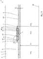
- Fig. 1 shows a downhole expandable metal tubular 1 to be expanded in a well 2 downhole to abut an inner face 3 of a borehole 4.
- the downhole expandable metal tubular 1 comprises a first section 6 having a first outer diameter OD 1 and two circumferential projections 7 having a second outer diameter OD 2 which is larger than the first outer diameter.
- the downhole expandable metal tubular 1 comprises a second section 8 arranged between the two projections 7, each projection having an inclined face 9 tapering from the second outer diameter OD 2 towards the second section 8.
- the second section 8 has a third outer diameter OD 3 which is smaller than the first outer diameter OD 1 in an unexpanded condition.
- a sealing element 10 is arranged between the projections 7 opposite the second section so that during expansion, the second section 8 bulges more radially outwards than the first section 6, forcing the sealing element radially outwards, as shown in Fig. 2 .
- the downhole expandable metal tubular 1 has been expanded so that the sealing element 10 is forced towards the inner face 3 of the borehole 4 and thus provides a firm seal so that fluid from a first zone 201 is prevented from passing to a second zone 202.
- the downhole expandable metal tubular 1 is more capable of sealing towards the inner face 3 of the borehole 4. This is due to the fact that the second section 8 bulges more outwards when the downhole expandable metal tubular 1 is expanded by means of fluid pressing directly or indirectly on the inner face of the downhole expandable metal tubular 1.
- the thinner section is more inclined to yield than the thicker first sections 6 and the projections 7.
- the expandable metal tubular 1 has an inner diameter ID 1 which is the same along its axial extension in the unexpanded condition, and in Fig. 2 , the inner diameter ID 1 opposite the second section 8 is increased in relation to the first section 6.
- the sealing element 10 is ring-shaped, and thus, if the second section 8 does not bulge outwards, the sealing element decreases as the downhole expandable metal tubular 1 is expanded. But by having the bulged second section 8, the sealing element 10 is forced radially outwards and is thus still capable of sealing, also after expansion of the downhole expandable metal tubular 1.
- the sealing element 10 has a trapezoidal cross-sectional shape corresponding to the shape formed by the projections 7 and thus substantially matching a cross-sectional shape of the second section 8 and the two projections.
- the first sections 6 have a first thickness t 1 and the second section 8 has a second thickness t 2 which is at least 25% smaller than the first thickness, preferably at least 40% smaller than the first thickness.
- the inclined face 9 of the projections 7 forms an angle ⁇ in relation to the axial extension, said angle being at least 110°, preferably 135°.
- the downhole expandable metal tubular 1 is part of an annular barrier 20 and comprises three second sections 8 separated by a first section 6.
- the annular barrier 20 is to be expanded in an annulus 21 between a well tubular structure 22 and the inner face 3 of the borehole 4 or a casing (not shown) downhole to provide zone isolation between a first zone and a second zone of the borehole 4 by dividing the annulus 21 into two parts, i.e. the first zone and the second zone.
- the annular barrier 20 comprises a tubular part 23 adapted to be mounted as part of the well tubular structure 22 and surrounds the tubular part and has an outer face 29 facing the inner face 3 of the borehole 4.
- Each end 35 of the downhole expandable metal tubular 1 is connected with the tubular part 23 by means of connection parts 24 defining an annular space 25 between the downhole expandable metal tubular and the tubular part 23.
- the annular barrier 20 may be expanded by letting pressurised fluid into the space through the opening 26 in the tubular part 23 or by the annular space 25 comprising a compound adapted to expand the annular space in that the compound comprises at least one thermally decomposable compound or chemical reactant adapted to generate gas or super-critical fluid upon decomposition.
- the sealing element 10 is arranged in the second section 8, and the second section including the sealing element has an outer diameter which is substantially the same as the second outer diameter of the projections 7 in the unexpanded condition of the downhole expandable metal tubular 1.
- the sealing element 10 is slidably arranged around the second section 8 so that the sealing element can move freely and is thus not fastened to the second section by means of glue or similar fastening methods.
- the sealing element may be made of an elastomer, rubber, polytetrafluoroethylene (PTFE) or another polymer.
- the downhole expandable metal tubular 1 is a patch to be expanded within a casing 5 already present in the well.
- the downhole expandable metal tubular 1 is expanded inside the casing 5 in order to seal off an area 28, such as a leak 27.
- the downhole expandable metal tubular 1 comprises a plurality of second sections 8 divided by first sections 6, and each second section 8 is surrounded by projections 7 in such a way that a projection 7 is arranged in each end of each second section 8.
- the downhole expandable metal tubular 1 is expanded by an expansion tool (not shown) which may be an expandable mandrel drawn through the downhole expandable metal tubular or a hydraulic inflatable bladder arranged inside the downhole expandable metal tubular 1.
- the bladder is made of elastomer and is thus capable of conforming to the inside of the downhole expandable metal tubular.
- fluid inside the bladder indirectly presses on the tubular, and the second section is thus forced to bulge outwards.
- the downhole expandable metal tubular may also be a liner hanger to be at least partly expanded within a casing or well tubular structure in a well, or a casing to be at least partly expanded within another casing.
- the compound comprised in the annular space of the annular barrier may be nitrogen.
- the compound may be selected from a group consisting of: ammonium dichromate, ammonium nitrate, ammonium nitrite, barium azide, sodium nitrate, or a combination thereof.
- the compound may be present in the form of a powder, a powder dispersed in a liquid or a powder dissolved in a liquid.
- a valve which may be a check valve, may be arranged in the opening of the annular barrier 20 through which pressurised fluid enters to expand the annular barrier.
- a sleeve may be arranged between the downhole expandable metal tubular 1 and the tubular part 23. The sleeve is connected with the tubular part 23 and the downhole expandable metal tubular 1, thus dividing the annular space 25 into a first space section and a second space section.
- the downhole expandable metal tubular 1 may have an aperture providing fluid communication between the first zone 201 or the second zone 202 and one of the space sections in order to equalise the pressure in the space if the formation pressure rises when expansion has taken place.
- the invention further relates to a downhole completion 100 comprising the well tubular structure 5 shown in Fig. 4 , and the downhole expandable metal tubular forming a patch to be expanded therein.
- the downhole completion 100 may also comprise the well tubular structure having an annular barrier 20, as shown in Fig. 3 , where the downhole expandable metal tubular 1 forms the expandable part surrounding the tubular part 23 of the annular barrier which is mounted as part of the well tubular structure 22.
- the downhole expandable metal tubular 1 has both the sealing element 10 and two split ring-shaped retaining elements 30 arranged between the projections 7.
- the split ring-shaped retaining elements 30 form a back-up for the sealing element so that when expanded, the split ring-shaped retaining elements 30 have more than one winding, meaning that when the downhole expandable metal tubular 1 is expanded from a first outer diameter to a second outer diameter, the windings of the split ring-shaped retaining elements 30 partly unwind.
- the split ring-shaped retaining elements 30 have three windings. However, in other embodiments, they may have two, four, five, six or seven windings, and an even higher number of windings is possible.
- the split ring-shaped retaining elements 30 and the sealing element 10 occupy the gap between the projections 7.
- the split ring-shaped retaining elements 30 abut the sealing element.
- the split ring-shaped retaining elements 30 ensure that the sealing element 10 is maintained and supported in the longitudinal extension of the downhole expandable metal tubular 1, even during expansion, so that the sealing element 10 retains its intended position and the sealing properties of the downhole expandable metal tubular 1 are enhanced.
- tests have shown that the sealing element 10 may withstand a higher pressure on either of the sides where the split ring-shaped retaining elements are positioned because the split ring-shaped retaining elements function as a back-up and support system for the sealing element.
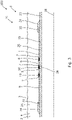
- Fig. 6 shows a downhole expandable metal tubular 1 to be expanded in a well 2 downhole to abut an inner face 3 of a borehole 4.
- the downhole expandable metal tubular 1 is shown in its unexpected condition and has an axial extension 38.
- the downhole expandable metal tubular 1 is corrugated, thereby forming projections 31 and grooves 32, and the downhole expandable metal tubular has a substantially even thickness along the axial extension.
- projections 31 between the grooves 32 comprising sealing elements
- the downhole expandable metal tubular 1 is expanded more evenly than if the downhole expandable metal tubular 1 also comprises grooves between the sealing elements 10.
- the part between the grooves are projections followed by grooves, and then, the material forming these intermediate grooves without sealing elements is free to expand, and expands more than the remaining part of the downhole expandable metal tubular and is thinned so that the collapse rating of the downhole expandable metal tubular is substantially decreased. Furthermore, by having a substantially even thickness along the axial extension, the expansion of the downhole expandable metal tubular is performed more evenly in the present solution of fig. 6 and thus the collapse rating is substantially improved compared to prior art expandable tubulars.
- the downhole expandable metal tubular 1 When seen in cross-section along the axial extension, as in Fig. 6 , the downhole expandable metal tubular 1 has square-shaped grooves 32.
- the projections 31 have an axial extension and a straight part substantially parallel to the axial extension 38.
- the grooves 32 have a smaller extension along the axial extension than the projections 31, and sealing elements 10 are arranged in the grooves so as to provide a better sealing ability when the downhole expandable metal tubular 1 is expanded to seal against the inner face 3 of the borehole.
- the downhole expandable metal tubular 1 when seen in cross-section along the axial extension, has a corrugated trapezoidal shape like a sheet piling.
- the grooves hereby have an inclined face 9 inclining from the projections 31 towards the groove 32.
- the downhole expandable metal tubular 1 of Fig. 7 is part of an annular barrier 20.
- the annular barrier 20 is to be expanded in an annulus 21 between a well tubular structure 22 and the inner face 3 of the borehole 4 or a casing (not shown) downhole to provide zone isolation between a first zone and a second zone of the borehole 4 by dividing the annulus 21 into two parts, i.e. the first zone and the second zone.
- the annular barrier 20 comprises a tubular part 23 adapted to be mounted as part of the well tubular structure 22 and surrounds the tubular part and has an outer face 29 facing the inner face 3 of the borehole 4.
- Each end 35 of the downhole expandable metal tubular 1 is connected with the tubular part 23 by means of connection parts 24 defining an annular space 25 between the downhole expandable metal tubular 1 and the tubular part 23.
- the downhole expandable metal tubular 1 may in another embodiment be connected to the tubular part 23 by welding.
- the annular barrier 20 may be expanded by letting pressurised fluid into the space through the opening 26 in the tubular part 23 or by the annular space 25 comprising a compound adapted to expand the annular space in that the compound comprises at least one thermally decomposable compound or chemical reactant adapted to generate gas or super-critical fluid upon decomposition.
- the downhole expandable metal tubular 1 ends in projections 31 which are end projections, and the ends are connected to the tubular part 23 of the annular barrier 20.
- the projections 31 abut the inner face 3 of the borehole 4 almost simultaneously with the sealing elements 10, and the material of the projections is not expanded to such an extent that it becomes thinner than the remaining part of the downhole expandable metal tubular.
- the collapse rating is improved in relation to prior art solutions where the part of the downhole expandable metal tubular between the sealing elements is further away from the inner face of the borehole and thus able to expand more.
- the projections 31 between the grooves 32 are smaller in extension than the end projections.
- both the sealing element 10 and a split ring-shaped retaining element 30 are arranged in at least one of the grooves 32, and the split ring-shaped retaining element forms a back-up for the sealing element.
- the split ring-shaped retaining element 30 has more than one winding, i.e. at least two in Fig. 8A , so that when the downhole expandable metal tubular 1 is expanded from the first outer diameter to the second outer diameter, the split ring-shaped retaining element partly unwinds. However, in other embodiments, it may have two, four, five, six or seven windings, and an even higher number of windings is possible.
- the split ring-shaped retaining element 30 and the sealing element 10 occupy the gap between the projections 31.
- the split ring-shaped retaining element 30 abuts the sealing element 10.
- the split ring-shaped retaining element 30 ensures that the sealing element 10 is maintained and supported in the longitudinal extension of the downhole expandable metal tubular 1 even during expansion, so that the sealing element 10 retains its intended position and the sealing properties of the downhole expandable metal tubular 1 are enhanced.
- the sealing element may withstand a higher pressure on the side where the split ring-shaped retaining element is positioned, since the split ring-shaped retaining ring functions as a back-up and support system for the sealing element.
- an intermediate element 41 is arranged between the split ring-shaped retaining element 30 and the sealing element 10.
- the split ring-shaped retaining element 30 partly overlaps the intermediate element 41.
- the intermediate element 41 may be made of a flexible material and is adapted to maintain the split ring-shaped retaining element 30 in position and function as protection and support of the sealing element 10.
- the split ring-shaped retaining element 30, the intermediate element 41 and the sealing element 10 are placed in the groove 32 between the first and second circumferential projections 31.
- the intermediate element 41 may be made of Teflon or a similar material being harder than that of the sealing element 10.
- Split ring-shaped retaining elements 30 may also be provided on either side of the sealing element 10, as shown in Fig. 10 .
- the downhole expandable metal tubular 1 is corrugated, thereby forming projections 31 and grooves 32, and has a corrugated cross-section like a sheet piling in the construction field.
- the downhole expandable metal tubular 1 is shaped e.g. by cold-working by means of rollers rotating within the downhole expandable metal tubular while being pressed towards the downhole expandable metal tubular forming the projections.
- the downhole expandable metal tubular is a sleeve having a substantially even thickness when seen in cross-section, as shown in Figs. 7-9
- the downhole expandable metal tubular is formed of projections 31 and grooves 32.
- the projections 31 have a straight part, and the grooves have a straight part when seen in cross-section.
- the downhole expandable metal tubular 1 comprises the second section 8 arranged between the two projections 7, and each projection has an inclined face 9 tapering from the second section 8 towards the second outer diameter OD 2 and is thus inclining in a direction opposite that of the downhole expandable metal tubular 1 shown in Fig. 1 .
- the inclined face 9 is also inclining in a direction opposite that of the downhole expandable metal tubular 1 shown in Fig. 1 , and the downhole expandable metal tubular 1 has a corrugated cross-section like a sheet piling.
- fluid or well fluid any kind of fluid that may be present in oil or gas wells downhole, such as natural gas, oil, oil mud, crude oil, water, etc.
- gas is meant any kind of gas composition present in a well, completion, or open hole
- oil is meant any kind of oil composition, such as crude oil, an oil-containing fluid, etc.
- Gas, oil, and water fluids may thus all comprise other elements or substances than gas, oil, and/or water, respectively.
- a casing By a casing, a production casing or a well tubular structure is meant any kind of pipe, tubing, tubular, liner, string etc. used downhole in relation to oil or natural gas production.
- a downhole tractor can be used to push the tool all the way into position in the well.
- the downhole tractor may have projectable arms having wheels, wherein the wheels contact the inner surface of the casing for propelling the tractor and the tool forward in the casing.
- a downhole tractor is any kind of driving tool capable of pushing or pulling tools in a well downhole, such as a Well Tractor ® .
Landscapes
- Geology (AREA)
- Life Sciences & Earth Sciences (AREA)
- Engineering & Computer Science (AREA)
- Mining & Mineral Resources (AREA)
- Environmental & Geological Engineering (AREA)
- Fluid Mechanics (AREA)
- Physics & Mathematics (AREA)
- General Life Sciences & Earth Sciences (AREA)
- Geochemistry & Mineralogy (AREA)
- Gasket Seals (AREA)
- Earth Drilling (AREA)
- Underground Structures, Protecting, Testing And Restoring Foundations (AREA)
- Laying Of Electric Cables Or Lines Outside (AREA)
Claims (12)
- Ringförmige Barriere (20), die in einem Ringraum (21) zwischen einer röhrenförmigen Bohrungsstruktur (22) und einer Innenfläche (3) eines Bohrlochs (5) oder einer Verrohrung (4) im Bohrloch expandierbar ist, um eine Zonenisolierung zwischen einer ersten Zone (201) und einer zweiten Zone (202) des Bohrlochs bereitzustellen, wobei die ringförmige Barriere aufweist:- ein rohrförmiger Teil, das dazu eingerichtet ist, als Teil der röhrenförmigen Bohrungsstruktur montiert zu werden,- ein im Bohrloch expandierbares Metallrohr, das den rohrförmigen Teil umgibt und eine Außenfläche (29) hat, die der Innenfläche des Bohrlochs oder der Verrohrung zugewandt ist, wobei jedes Ende des im Bohrloch expandierbaren Metallrohrs mit dem rohrförmigen Teil verbunden ist, und- einen ringförmigen Raum (25) zwischen dem im Bohrloch expandierbaren Metallrohr und dem rohrförmigen Teil,dadurch gekennzeichnet, dass das im Bohrloch expandierbare Metallrohr eine axiale Erstreckung hat, die in einem Bohrungs-Bohrloch expandierbar ist, um an der Innenfläche der Verrohrung oder des Bohrlochs anzuliegen, wobei das im Bohrloch expandierbare Metallrohr gerippt ist, um Vorsprünge (31) und Nuten (32) zu bilden, und das im Bohrloch expandierbare Metallrohr eine im Wesentlichen gleichmäßige Dicke (t) hat.
- Ringförmige Barriere nach Anspruch 1, wobei in mindestens einer der Nuten ein Dichtelement angeordnet ist
- Ringförmige Barriere nach Anspruch 1 oder 2, wobei die Nuten eine geringere Erstreckung entlang der axialen Erstreckung haben als die Vorsprünge.
- Ringförmige Barriere nach einem der Ansprüche 1 bis 3, wobei die Vorsprünge einen geraden Teil aufweisen, der im Wesentlichen parallel zur axialen Erstreckung verläuft
- Ringförmige Barriere nach einem der Ansprüche 1 bis 3, wobei das im Bohrloch expandierbare Metallrohr in Vorsprüngen endet, die Endvorsprünge sind.
- Ringförmige Barriere nach Anspruch 5, wobei die Vorsprünge zwischen den Nuten eine geringere Erstreckung haben als die Endvorsprünge.
- Ringförmige Barriere nach einem der Ansprüche, wobei das im Bohrloch expandierbare Metallrohr im Querschnitt entlang der axialen Erstreckung eine gerippte quadratische oder trapezförmige Form hat.
- Ringförmige Barriere nach einem der Ansprüche 2 und 3 bis 7 (wenn abhängig von Anspruch 2), wobei das Dichtungselement und ein geteiltes ringförmiges Halteelement zwischen den Vorsprüngen angeordnet sind, wobei das geteilte ringförmige Halteelement eine Sicherung für das Dichtungselement bildet.
- Ringförmige Barriere nach Anspruch 8, wobei das geteilte ringförmige Halteelement mehr als eine Windung aufweist, so dass sich das geteilte ringförmige Halteelement teilweise abwickelt, wenn das expandierbare Rohr von dem ersten Außendurchmesser auf den zweiten Außendurchmesser expandiert wird.
- Ringförmige Barriere nach Anspruch 8 oder 9, wobei zwischen dem geteilten ringförmigen Halteelement und dem Dichtungselement ein Zwischenelement angeordnet sein kann.
- Bohrlochkomplettierung, aufweisend:- eine röhrenförmige Bohrungsstruktur, und- eine ringförmige Barriere nach Anspruch 1-10,wobei der rohrförmige Teil der ringförmigen Barriere als Teil der rohrförmigen Bohrungsstruktur montiert ist
- Dichtungsexpansionsverfahren, das die folgenden Schritte aufweist:- Anordnen einer Bohrlochkomplettierung nach Anspruch 11, und- Expandieren des im Bohrloch expandierbaren Metallrohrs der ringförmigen Barriere, so dass es an einer Verrohrung oder einem Bohrloch anliegt, um eine Zonenisolierung zwischen einer ersten Zone und einer zweiten Zone der Verrohrung oder des Bohrlochs bereitzustellen.
Applications Claiming Priority (3)
| Application Number | Priority Date | Filing Date | Title |
|---|---|---|---|
| EP14171117.6A EP2952672A1 (de) | 2014-06-04 | 2014-06-04 | Expandierbares Bohrlochmetallrohr |
| EP15726193.4A EP3152389B1 (de) | 2014-06-04 | 2015-06-04 | Expandierbares bohrlochmetallrohr |
| PCT/EP2015/062495 WO2015185683A1 (en) | 2014-06-04 | 2015-06-04 | Downhole expandable metal tubular |
Related Parent Applications (1)
| Application Number | Title | Priority Date | Filing Date |
|---|---|---|---|
| EP15726193.4A Division EP3152389B1 (de) | 2014-06-04 | 2015-06-04 | Expandierbares bohrlochmetallrohr |
Publications (2)
| Publication Number | Publication Date |
|---|---|
| EP3670826A1 EP3670826A1 (de) | 2020-06-24 |
| EP3670826B1 true EP3670826B1 (de) | 2022-11-23 |
Family
ID=50927938
Family Applications (3)
| Application Number | Title | Priority Date | Filing Date |
|---|---|---|---|
| EP14171117.6A Withdrawn EP2952672A1 (de) | 2014-06-04 | 2014-06-04 | Expandierbares Bohrlochmetallrohr |
| EP20156643.7A Active EP3670826B1 (de) | 2014-06-04 | 2015-06-04 | Expandierbares bohrlochmetallrohr |
| EP15726193.4A Active EP3152389B1 (de) | 2014-06-04 | 2015-06-04 | Expandierbares bohrlochmetallrohr |
Family Applications Before (1)
| Application Number | Title | Priority Date | Filing Date |
|---|---|---|---|
| EP14171117.6A Withdrawn EP2952672A1 (de) | 2014-06-04 | 2014-06-04 | Expandierbares Bohrlochmetallrohr |
Family Applications After (1)
| Application Number | Title | Priority Date | Filing Date |
|---|---|---|---|
| EP15726193.4A Active EP3152389B1 (de) | 2014-06-04 | 2015-06-04 | Expandierbares bohrlochmetallrohr |
Country Status (12)
| Country | Link |
|---|---|
| US (2) | US10711559B2 (de) |
| EP (3) | EP2952672A1 (de) |
| CN (1) | CN106460480A (de) |
| AU (1) | AU2015270490B2 (de) |
| BR (2) | BR112016026896B1 (de) |
| CA (1) | CA2950038A1 (de) |
| DK (2) | DK3670826T3 (de) |
| MX (1) | MX2016015723A (de) |
| MY (1) | MY184118A (de) |
| RU (1) | RU2697089C2 (de) |
| SA (1) | SA516380411B1 (de) |
| WO (1) | WO2015185683A1 (de) |
Families Citing this family (15)
| Publication number | Priority date | Publication date | Assignee | Title |
|---|---|---|---|---|
| EP2853681A1 (de) * | 2013-09-30 | 2015-04-01 | Welltec A/S | Wärmeexpandierte ringförmige Barriere |
| EP2952672A1 (de) | 2014-06-04 | 2015-12-09 | Welltec A/S | Expandierbares Bohrlochmetallrohr |
| WO2017001653A1 (en) * | 2015-07-01 | 2017-01-05 | Shell Internationale Research Maatschappij B.V. | Method and system for sealing an annulur space around an expanded well tubular |
| EP3255240A1 (de) | 2016-06-10 | 2017-12-13 | Welltec A/S | Bohrlochspreizsystem |
| GB2552799B (en) * | 2016-08-09 | 2019-05-22 | Morphpackers Ltd | Morphable packer |
| DK3658744T3 (da) * | 2017-07-27 | 2022-03-07 | Welltec Oilfield Solutions Ag | Ringformet barriere til brønde med små diametre |
| DE102017117868A1 (de) | 2017-08-07 | 2019-02-07 | Benteler Steel/Tube Gmbh | Rohrelement und Verfahren zum Befestigen eines derartigen Rohrelementes in einer rohrförmigen Öffnung |
| AU2017439376B2 (en) * | 2017-11-13 | 2023-06-01 | Halliburton Energy Services, Inc. | Swellable metal for non-elastomeric O-rings, seal stacks, and gaskets |
| RU2718456C1 (ru) * | 2019-04-01 | 2020-04-06 | Михаил Александрович Самохвалов | Гидравлический пакер |
| EP4355978A4 (de) * | 2021-06-15 | 2025-03-05 | Dynamic Tubular Systems, LLC | Geothermisches bohrlochverfahren und system |
| CN113279720B (zh) * | 2021-06-30 | 2022-03-11 | 牡丹江市新翔石油机械有限责任公司 | 一种双向胀封机构及其双向胀封封隔器 |
| EP4112873A1 (de) * | 2021-07-01 | 2023-01-04 | Welltec Oilfield Solutions AG | Ringförmige barriere |
| EP4430269A1 (de) * | 2021-11-10 | 2024-09-18 | Welltec Manufacturing Center Completions ApS | Expandierbares bohrlochrohr |
| EP4290047A1 (de) * | 2022-06-10 | 2023-12-13 | Isealate AS | Aufweitbare bohrloch-rohranordnung |
| US12305459B2 (en) * | 2022-06-15 | 2025-05-20 | Halliburton Energy Services, Inc. | Sealing/anchoring tool employing an expandable metal circlet |
Family Cites Families (26)
| Publication number | Priority date | Publication date | Assignee | Title |
|---|---|---|---|---|
| US3784214A (en) * | 1971-10-18 | 1974-01-08 | J Tamplen | Seal that is responsive to either mechanical or pressure force |
| US4349204A (en) * | 1981-04-29 | 1982-09-14 | Lynes, Inc. | Non-extruding inflatable packer assembly |
| US4753444A (en) * | 1986-10-30 | 1988-06-28 | Otis Engineering Corporation | Seal and seal assembly for well tools |
| AU6227994A (en) * | 1993-03-04 | 1994-09-26 | Baker Hughes Incorporated | Straight bore metal-to-metal wellbore seal apparatus and method of sealing in a wellbore |
| RU2083798C1 (ru) * | 1995-01-17 | 1997-07-10 | Товарищество с ограниченной ответственностью "ЛОКС" | Способ разобщения пластов в скважине профильным перекрывателем |
| US5542473A (en) * | 1995-06-01 | 1996-08-06 | Pringle; Ronald E. | Simplified sealing and anchoring device for a well tool |
| NO301945B1 (no) * | 1995-09-08 | 1997-12-29 | Broennteknologiutvikling As | Ekspanderende opphentbar broplugg |
| RU2101465C1 (ru) * | 1996-09-13 | 1998-01-10 | Расим Шахимарданович Тугушев | Устройство для цементирования обсадной колонны в скважине |
| US5775429A (en) * | 1997-02-03 | 1998-07-07 | Pes, Inc. | Downhole packer |
| US6565093B2 (en) * | 2001-03-01 | 2003-05-20 | Halliburton Energy Services, Inc. | Seal structure for downhole tool |
| US7387170B2 (en) * | 2002-04-05 | 2008-06-17 | Baker Hughes Incorporated | Expandable packer with mounted exterior slips and seal |
| RU2224872C1 (ru) * | 2002-07-29 | 2004-02-27 | Государственное унитарное предприятие Научно-производственное объединение "Гидротрубопровод" | Пакер |
| US6854522B2 (en) * | 2002-09-23 | 2005-02-15 | Halliburton Energy Services, Inc. | Annular isolators for expandable tubulars in wellbores |
| GB0320252D0 (en) * | 2003-08-29 | 2003-10-01 | Caledyne Ltd | Improved seal |
| US7347274B2 (en) * | 2004-01-27 | 2008-03-25 | Schlumberger Technology Corporation | Annular barrier tool |
| RU2282711C1 (ru) * | 2004-12-28 | 2006-08-27 | Открытое акционерное общество "Газпром" (ОАО "Газпром") | Заколонный пакер |
| AU2007346700B2 (en) * | 2007-02-06 | 2013-10-31 | Halliburton Energy Services, Inc. | Swellable packer with enhanced sealing capability |
| CA2715647C (en) * | 2008-02-19 | 2013-10-01 | Weatherford/Lamb, Inc. | Expandable packer |
| US8336634B2 (en) * | 2008-03-28 | 2012-12-25 | Schlumberger Technology Corporation | System and method for packing |
| EP2312119A1 (de) * | 2009-10-07 | 2011-04-20 | Welltec A/S | Ringförmige Absperrung |
| WO2012045355A1 (en) * | 2010-10-07 | 2012-04-12 | Welltec A/S | An annular barrier |
| US8550178B2 (en) * | 2011-03-09 | 2013-10-08 | Baker Hughes Incorporated | Expandable isolation packer |
| US9169724B2 (en) * | 2012-02-23 | 2015-10-27 | Halliburton Energy Services, Inc. | Expandable conical tubing run through production tubing and into open hole |
| EP2644820A1 (de) * | 2012-03-30 | 2013-10-02 | Welltec A/S | Ringförmige Absperrung mit Dichtung |
| US9568103B2 (en) * | 2013-04-29 | 2017-02-14 | Baker Hughes Incorporated | Expandable high pressure and high temperature seal |
| EP2952672A1 (de) | 2014-06-04 | 2015-12-09 | Welltec A/S | Expandierbares Bohrlochmetallrohr |
-
2014
- 2014-06-04 EP EP14171117.6A patent/EP2952672A1/de not_active Withdrawn
-
2015
- 2015-06-04 CN CN201580026429.0A patent/CN106460480A/zh active Pending
- 2015-06-04 DK DK20156643.7T patent/DK3670826T3/da active
- 2015-06-04 DK DK15726193.4T patent/DK3152389T3/da active
- 2015-06-04 MX MX2016015723A patent/MX2016015723A/es unknown
- 2015-06-04 BR BR112016026896-2A patent/BR112016026896B1/pt active IP Right Grant
- 2015-06-04 BR BR122022009865-7A patent/BR122022009865B1/pt active IP Right Grant
- 2015-06-04 EP EP20156643.7A patent/EP3670826B1/de active Active
- 2015-06-04 AU AU2015270490A patent/AU2015270490B2/en active Active
- 2015-06-04 CA CA2950038A patent/CA2950038A1/en not_active Abandoned
- 2015-06-04 RU RU2016150307A patent/RU2697089C2/ru active
- 2015-06-04 MY MYPI2016002053A patent/MY184118A/en unknown
- 2015-06-04 WO PCT/EP2015/062495 patent/WO2015185683A1/en not_active Ceased
- 2015-06-04 EP EP15726193.4A patent/EP3152389B1/de active Active
- 2015-06-04 US US15/315,926 patent/US10711559B2/en active Active
-
2016
- 2016-12-01 SA SA516380411A patent/SA516380411B1/ar unknown
-
2020
- 2020-06-09 US US16/896,509 patent/US11473392B2/en active Active
Also Published As
| Publication number | Publication date |
|---|---|
| BR112016026896B1 (pt) | 2022-08-30 |
| DK3152389T3 (da) | 2020-05-18 |
| EP2952672A1 (de) | 2015-12-09 |
| MY184118A (en) | 2021-03-18 |
| RU2016150307A3 (de) | 2019-01-18 |
| EP3152389B1 (de) | 2020-02-12 |
| US20170101846A1 (en) | 2017-04-13 |
| SA516380411B1 (ar) | 2023-01-05 |
| US10711559B2 (en) | 2020-07-14 |
| MX2016015723A (es) | 2017-03-16 |
| AU2015270490A1 (en) | 2017-01-19 |
| RU2697089C2 (ru) | 2019-08-12 |
| EP3152389A1 (de) | 2017-04-12 |
| CA2950038A1 (en) | 2015-12-10 |
| CN106460480A (zh) | 2017-02-22 |
| BR122022009865B1 (pt) | 2023-03-07 |
| AU2015270490B2 (en) | 2017-08-31 |
| WO2015185683A1 (en) | 2015-12-10 |
| US11473392B2 (en) | 2022-10-18 |
| RU2016150307A (ru) | 2018-07-10 |
| BR112016026896A2 (de) | 2017-08-15 |
| US20200300057A1 (en) | 2020-09-24 |
| EP3670826A1 (de) | 2020-06-24 |
| DK3670826T3 (da) | 2023-02-27 |
Similar Documents
| Publication | Publication Date | Title |
|---|---|---|
| US11473392B2 (en) | Downhole expandable metal tubular | |
| US10100598B2 (en) | Downhole expandable metal tubular | |
| WO2018083069A1 (en) | Method for sealing cavities in or adjacent to a cured cement sheath surrounding a well casing | |
| US20150041154A1 (en) | Annular barrier having a flexible connection | |
| NO20170190A1 (en) | Improvements In Or Relating To Morphing Tubulars | |
| EP3990746B1 (de) | Ringförmige barriere mit pressverbindungen | |
| EP3987150B1 (de) | Ringbarriere mit verzahnter verbindung | |
| AU2019373350B2 (en) | Annular barrier | |
| EP3658744B1 (de) | Ringförmige barriere für bohrlöcher mit kleinem durchmesser | |
| EP3480421A1 (de) | Ringförmige barriere für bohrlöcher mit kleinem durchmesser |
Legal Events
| Date | Code | Title | Description |
|---|---|---|---|
| PUAI | Public reference made under article 153(3) epc to a published international application that has entered the european phase |
Free format text: ORIGINAL CODE: 0009012 |
|
| STAA | Information on the status of an ep patent application or granted ep patent |
Free format text: STATUS: THE APPLICATION HAS BEEN PUBLISHED |
|
| AC | Divisional application: reference to earlier application |
Ref document number: 3152389 Country of ref document: EP Kind code of ref document: P |
|
| AK | Designated contracting states |
Kind code of ref document: A1 Designated state(s): AL AT BE BG CH CY CZ DE DK EE ES FI FR GB GR HR HU IE IS IT LI LT LU LV MC MK MT NL NO PL PT RO RS SE SI SK SM TR |
|
| STAA | Information on the status of an ep patent application or granted ep patent |
Free format text: STATUS: REQUEST FOR EXAMINATION WAS MADE |
|
| 17P | Request for examination filed |
Effective date: 20201223 |
|
| RBV | Designated contracting states (corrected) |
Designated state(s): AL AT BE BG CH CY CZ DE DK EE ES FI FR GB GR HR HU IE IS IT LI LT LU LV MC MK MT NL NO PL PT RO RS SE SI SK SM TR |
|
| STAA | Information on the status of an ep patent application or granted ep patent |
Free format text: STATUS: EXAMINATION IS IN PROGRESS |
|
| 17Q | First examination report despatched |
Effective date: 20210503 |
|
| GRAP | Despatch of communication of intention to grant a patent |
Free format text: ORIGINAL CODE: EPIDOSNIGR1 |
|
| STAA | Information on the status of an ep patent application or granted ep patent |
Free format text: STATUS: GRANT OF PATENT IS INTENDED |
|
| INTG | Intention to grant announced |
Effective date: 20220204 |
|
| GRAJ | Information related to disapproval of communication of intention to grant by the applicant or resumption of examination proceedings by the epo deleted |
Free format text: ORIGINAL CODE: EPIDOSDIGR1 |
|
| STAA | Information on the status of an ep patent application or granted ep patent |
Free format text: STATUS: EXAMINATION IS IN PROGRESS |
|
| GRAS | Grant fee paid |
Free format text: ORIGINAL CODE: EPIDOSNIGR3 |
|
| STAA | Information on the status of an ep patent application or granted ep patent |
Free format text: STATUS: GRANT OF PATENT IS INTENDED |
|
| GRAP | Despatch of communication of intention to grant a patent |
Free format text: ORIGINAL CODE: EPIDOSNIGR1 |
|
| INTC | Intention to grant announced (deleted) | ||
| INTG | Intention to grant announced |
Effective date: 20220630 |
|
| GRAA | (expected) grant |
Free format text: ORIGINAL CODE: 0009210 |
|
| STAA | Information on the status of an ep patent application or granted ep patent |
Free format text: STATUS: THE PATENT HAS BEEN GRANTED |
|
| AC | Divisional application: reference to earlier application |
Ref document number: 3152389 Country of ref document: EP Kind code of ref document: P |
|
| AK | Designated contracting states |
Kind code of ref document: B1 Designated state(s): AL AT BE BG CH CY CZ DE DK EE ES FI FR GB GR HR HU IE IS IT LI LT LU LV MC MK MT NL NO PL PT RO RS SE SI SK SM TR |
|
| REG | Reference to a national code |
Ref country code: GB Ref legal event code: FG4D |
|
| REG | Reference to a national code |
Ref country code: CH Ref legal event code: EP |
|
| REG | Reference to a national code |
Ref country code: DE Ref legal event code: R096 Ref document number: 602015081749 Country of ref document: DE |
|
| REG | Reference to a national code |
Ref country code: AT Ref legal event code: REF Ref document number: 1533239 Country of ref document: AT Kind code of ref document: T Effective date: 20221215 |
|
| REG | Reference to a national code |
Ref country code: IE Ref legal event code: FG4D |
|
| REG | Reference to a national code |
Ref country code: DK Ref legal event code: T3 Effective date: 20230221 Ref country code: NO Ref legal event code: T2 Effective date: 20221123 |
|
| REG | Reference to a national code |
Ref country code: LT Ref legal event code: MG9D |
|
| REG | Reference to a national code |
Ref country code: NL Ref legal event code: MP Effective date: 20221123 |
|
| REG | Reference to a national code |
Ref country code: AT Ref legal event code: MK05 Ref document number: 1533239 Country of ref document: AT Kind code of ref document: T Effective date: 20221123 |
|
| PG25 | Lapsed in a contracting state [announced via postgrant information from national office to epo] |
Ref country code: SE Free format text: LAPSE BECAUSE OF FAILURE TO SUBMIT A TRANSLATION OF THE DESCRIPTION OR TO PAY THE FEE WITHIN THE PRESCRIBED TIME-LIMIT Effective date: 20221123 Ref country code: PT Free format text: LAPSE BECAUSE OF FAILURE TO SUBMIT A TRANSLATION OF THE DESCRIPTION OR TO PAY THE FEE WITHIN THE PRESCRIBED TIME-LIMIT Effective date: 20230323 Ref country code: LT Free format text: LAPSE BECAUSE OF FAILURE TO SUBMIT A TRANSLATION OF THE DESCRIPTION OR TO PAY THE FEE WITHIN THE PRESCRIBED TIME-LIMIT Effective date: 20221123 Ref country code: FI Free format text: LAPSE BECAUSE OF FAILURE TO SUBMIT A TRANSLATION OF THE DESCRIPTION OR TO PAY THE FEE WITHIN THE PRESCRIBED TIME-LIMIT Effective date: 20221123 Ref country code: ES Free format text: LAPSE BECAUSE OF FAILURE TO SUBMIT A TRANSLATION OF THE DESCRIPTION OR TO PAY THE FEE WITHIN THE PRESCRIBED TIME-LIMIT Effective date: 20221123 Ref country code: AT Free format text: LAPSE BECAUSE OF FAILURE TO SUBMIT A TRANSLATION OF THE DESCRIPTION OR TO PAY THE FEE WITHIN THE PRESCRIBED TIME-LIMIT Effective date: 20221123 |
|
| PG25 | Lapsed in a contracting state [announced via postgrant information from national office to epo] |
Ref country code: RS Free format text: LAPSE BECAUSE OF FAILURE TO SUBMIT A TRANSLATION OF THE DESCRIPTION OR TO PAY THE FEE WITHIN THE PRESCRIBED TIME-LIMIT Effective date: 20221123 Ref country code: PL Free format text: LAPSE BECAUSE OF FAILURE TO SUBMIT A TRANSLATION OF THE DESCRIPTION OR TO PAY THE FEE WITHIN THE PRESCRIBED TIME-LIMIT Effective date: 20221123 Ref country code: LV Free format text: LAPSE BECAUSE OF FAILURE TO SUBMIT A TRANSLATION OF THE DESCRIPTION OR TO PAY THE FEE WITHIN THE PRESCRIBED TIME-LIMIT Effective date: 20221123 Ref country code: IS Free format text: LAPSE BECAUSE OF FAILURE TO SUBMIT A TRANSLATION OF THE DESCRIPTION OR TO PAY THE FEE WITHIN THE PRESCRIBED TIME-LIMIT Effective date: 20230323 Ref country code: HR Free format text: LAPSE BECAUSE OF FAILURE TO SUBMIT A TRANSLATION OF THE DESCRIPTION OR TO PAY THE FEE WITHIN THE PRESCRIBED TIME-LIMIT Effective date: 20221123 Ref country code: GR Free format text: LAPSE BECAUSE OF FAILURE TO SUBMIT A TRANSLATION OF THE DESCRIPTION OR TO PAY THE FEE WITHIN THE PRESCRIBED TIME-LIMIT Effective date: 20230224 |
|
| P01 | Opt-out of the competence of the unified patent court (upc) registered |
Effective date: 20230523 |
|
| PG25 | Lapsed in a contracting state [announced via postgrant information from national office to epo] |
Ref country code: NL Free format text: LAPSE BECAUSE OF FAILURE TO SUBMIT A TRANSLATION OF THE DESCRIPTION OR TO PAY THE FEE WITHIN THE PRESCRIBED TIME-LIMIT Effective date: 20221123 |
|
| PG25 | Lapsed in a contracting state [announced via postgrant information from national office to epo] |
Ref country code: SM Free format text: LAPSE BECAUSE OF FAILURE TO SUBMIT A TRANSLATION OF THE DESCRIPTION OR TO PAY THE FEE WITHIN THE PRESCRIBED TIME-LIMIT Effective date: 20221123 Ref country code: RO Free format text: LAPSE BECAUSE OF FAILURE TO SUBMIT A TRANSLATION OF THE DESCRIPTION OR TO PAY THE FEE WITHIN THE PRESCRIBED TIME-LIMIT Effective date: 20221123 Ref country code: EE Free format text: LAPSE BECAUSE OF FAILURE TO SUBMIT A TRANSLATION OF THE DESCRIPTION OR TO PAY THE FEE WITHIN THE PRESCRIBED TIME-LIMIT Effective date: 20221123 Ref country code: CZ Free format text: LAPSE BECAUSE OF FAILURE TO SUBMIT A TRANSLATION OF THE DESCRIPTION OR TO PAY THE FEE WITHIN THE PRESCRIBED TIME-LIMIT Effective date: 20221123 |
|
| REG | Reference to a national code |
Ref country code: DE Ref legal event code: R097 Ref document number: 602015081749 Country of ref document: DE |
|
| PG25 | Lapsed in a contracting state [announced via postgrant information from national office to epo] |
Ref country code: SK Free format text: LAPSE BECAUSE OF FAILURE TO SUBMIT A TRANSLATION OF THE DESCRIPTION OR TO PAY THE FEE WITHIN THE PRESCRIBED TIME-LIMIT Effective date: 20221123 Ref country code: AL Free format text: LAPSE BECAUSE OF FAILURE TO SUBMIT A TRANSLATION OF THE DESCRIPTION OR TO PAY THE FEE WITHIN THE PRESCRIBED TIME-LIMIT Effective date: 20221123 |
|
| PLBE | No opposition filed within time limit |
Free format text: ORIGINAL CODE: 0009261 |
|
| STAA | Information on the status of an ep patent application or granted ep patent |
Free format text: STATUS: NO OPPOSITION FILED WITHIN TIME LIMIT |
|
| 26N | No opposition filed |
Effective date: 20230824 |
|
| PG25 | Lapsed in a contracting state [announced via postgrant information from national office to epo] |
Ref country code: SI Free format text: LAPSE BECAUSE OF FAILURE TO SUBMIT A TRANSLATION OF THE DESCRIPTION OR TO PAY THE FEE WITHIN THE PRESCRIBED TIME-LIMIT Effective date: 20221123 |
|
| REG | Reference to a national code |
Ref country code: DE Ref legal event code: R119 Ref document number: 602015081749 Country of ref document: DE |
|
| PG25 | Lapsed in a contracting state [announced via postgrant information from national office to epo] |
Ref country code: MC Free format text: LAPSE BECAUSE OF FAILURE TO SUBMIT A TRANSLATION OF THE DESCRIPTION OR TO PAY THE FEE WITHIN THE PRESCRIBED TIME-LIMIT Effective date: 20221123 |
|
| PG25 | Lapsed in a contracting state [announced via postgrant information from national office to epo] |
Ref country code: MC Free format text: LAPSE BECAUSE OF FAILURE TO SUBMIT A TRANSLATION OF THE DESCRIPTION OR TO PAY THE FEE WITHIN THE PRESCRIBED TIME-LIMIT Effective date: 20221123 |
|
| REG | Reference to a national code |
Ref country code: CH Ref legal event code: PL |
|
| REG | Reference to a national code |
Ref country code: BE Ref legal event code: MM Effective date: 20230630 |
|
| PG25 | Lapsed in a contracting state [announced via postgrant information from national office to epo] |
Ref country code: LU Free format text: LAPSE BECAUSE OF NON-PAYMENT OF DUE FEES Effective date: 20230604 |
|
| REG | Reference to a national code |
Ref country code: IE Ref legal event code: MM4A |
|
| PG25 | Lapsed in a contracting state [announced via postgrant information from national office to epo] |
Ref country code: LU Free format text: LAPSE BECAUSE OF NON-PAYMENT OF DUE FEES Effective date: 20230604 |
|
| PG25 | Lapsed in a contracting state [announced via postgrant information from national office to epo] |
Ref country code: IE Free format text: LAPSE BECAUSE OF NON-PAYMENT OF DUE FEES Effective date: 20230604 |
|
| PG25 | Lapsed in a contracting state [announced via postgrant information from national office to epo] |
Ref country code: IE Free format text: LAPSE BECAUSE OF NON-PAYMENT OF DUE FEES Effective date: 20230604 Ref country code: DE Free format text: LAPSE BECAUSE OF NON-PAYMENT OF DUE FEES Effective date: 20240103 Ref country code: CH Free format text: LAPSE BECAUSE OF NON-PAYMENT OF DUE FEES Effective date: 20230630 |
|
| PG25 | Lapsed in a contracting state [announced via postgrant information from national office to epo] |
Ref country code: IT Free format text: LAPSE BECAUSE OF FAILURE TO SUBMIT A TRANSLATION OF THE DESCRIPTION OR TO PAY THE FEE WITHIN THE PRESCRIBED TIME-LIMIT Effective date: 20221123 Ref country code: BE Free format text: LAPSE BECAUSE OF NON-PAYMENT OF DUE FEES Effective date: 20230630 |
|
| PG25 | Lapsed in a contracting state [announced via postgrant information from national office to epo] |
Ref country code: BG Free format text: LAPSE BECAUSE OF FAILURE TO SUBMIT A TRANSLATION OF THE DESCRIPTION OR TO PAY THE FEE WITHIN THE PRESCRIBED TIME-LIMIT Effective date: 20221123 |
|
| REG | Reference to a national code |
Ref country code: GB Ref legal event code: 732E Free format text: REGISTERED BETWEEN 20241017 AND 20241023 |
|
| PG25 | Lapsed in a contracting state [announced via postgrant information from national office to epo] |
Ref country code: BG Free format text: LAPSE BECAUSE OF FAILURE TO SUBMIT A TRANSLATION OF THE DESCRIPTION OR TO PAY THE FEE WITHIN THE PRESCRIBED TIME-LIMIT Effective date: 20221123 |
|
| PGFP | Annual fee paid to national office [announced via postgrant information from national office to epo] |
Ref country code: GB Payment date: 20250618 Year of fee payment: 11 Ref country code: DK Payment date: 20250618 Year of fee payment: 11 |
|
| PGFP | Annual fee paid to national office [announced via postgrant information from national office to epo] |
Ref country code: NO Payment date: 20250618 Year of fee payment: 11 |
|
| PGFP | Annual fee paid to national office [announced via postgrant information from national office to epo] |
Ref country code: FR Payment date: 20250617 Year of fee payment: 11 |
|
| PG25 | Lapsed in a contracting state [announced via postgrant information from national office to epo] |
Ref country code: CY Free format text: LAPSE BECAUSE OF FAILURE TO SUBMIT A TRANSLATION OF THE DESCRIPTION OR TO PAY THE FEE WITHIN THE PRESCRIBED TIME-LIMIT; INVALID AB INITIO Effective date: 20150604 |
|
| PG25 | Lapsed in a contracting state [announced via postgrant information from national office to epo] |
Ref country code: HU Free format text: LAPSE BECAUSE OF FAILURE TO SUBMIT A TRANSLATION OF THE DESCRIPTION OR TO PAY THE FEE WITHIN THE PRESCRIBED TIME-LIMIT; INVALID AB INITIO Effective date: 20150604 |
|
| PG25 | Lapsed in a contracting state [announced via postgrant information from national office to epo] |
Ref country code: TR Free format text: LAPSE BECAUSE OF FAILURE TO SUBMIT A TRANSLATION OF THE DESCRIPTION OR TO PAY THE FEE WITHIN THE PRESCRIBED TIME-LIMIT Effective date: 20221123 |