EP3670833B1 - Rotationskolbenmotor mit gehäuse mit siliziumkarbidplatte - Google Patents
Rotationskolbenmotor mit gehäuse mit siliziumkarbidplatte Download PDFInfo
- Publication number
- EP3670833B1 EP3670833B1 EP19219031.2A EP19219031A EP3670833B1 EP 3670833 B1 EP3670833 B1 EP 3670833B1 EP 19219031 A EP19219031 A EP 19219031A EP 3670833 B1 EP3670833 B1 EP 3670833B1
- Authority
- EP
- European Patent Office
- Prior art keywords
- plates
- peripheral wall
- internal combustion
- end walls
- combustion engine
- Prior art date
- Legal status (The legal status is an assumption and is not a legal conclusion. Google has not performed a legal analysis and makes no representation as to the accuracy of the status listed.)
- Active
Links
Images


Classifications
-
- F—MECHANICAL ENGINEERING; LIGHTING; HEATING; WEAPONS; BLASTING
- F01—MACHINES OR ENGINES IN GENERAL; ENGINE PLANTS IN GENERAL; STEAM ENGINES
- F01C—ROTARY-PISTON OR OSCILLATING-PISTON MACHINES OR ENGINES
- F01C1/00—Rotary-piston machines or engines
- F01C1/22—Rotary-piston machines or engines of internal-axis type with equidirectional movement of co-operating members at the points of engagement, or with one of the co-operating members being stationary, the inner member having more teeth or tooth- equivalents than the outer member
-
- F—MECHANICAL ENGINEERING; LIGHTING; HEATING; WEAPONS; BLASTING
- F01—MACHINES OR ENGINES IN GENERAL; ENGINE PLANTS IN GENERAL; STEAM ENGINES
- F01C—ROTARY-PISTON OR OSCILLATING-PISTON MACHINES OR ENGINES
- F01C19/00—Sealing arrangements in rotary-piston machines or engines
- F01C19/10—Sealings for working fluids between radially and axially movable parts
-
- F—MECHANICAL ENGINEERING; LIGHTING; HEATING; WEAPONS; BLASTING
- F01—MACHINES OR ENGINES IN GENERAL; ENGINE PLANTS IN GENERAL; STEAM ENGINES
- F01C—ROTARY-PISTON OR OSCILLATING-PISTON MACHINES OR ENGINES
- F01C21/00—Component parts, details or accessories not provided for in groups F01C1/00 - F01C20/00
- F01C21/06—Heating; Cooling; Heat insulation
-
- F—MECHANICAL ENGINEERING; LIGHTING; HEATING; WEAPONS; BLASTING
- F01—MACHINES OR ENGINES IN GENERAL; ENGINE PLANTS IN GENERAL; STEAM ENGINES
- F01C—ROTARY-PISTON OR OSCILLATING-PISTON MACHINES OR ENGINES
- F01C21/00—Component parts, details or accessories not provided for in groups F01C1/00 - F01C20/00
- F01C21/10—Outer members for co-operation with rotary pistons; Casings
- F01C21/104—Stators; Members defining the outer boundaries of the working chamber
- F01C21/108—Stators; Members defining the outer boundaries of the working chamber with an axial surface, e.g. side plates
-
- F—MECHANICAL ENGINEERING; LIGHTING; HEATING; WEAPONS; BLASTING
- F04—POSITIVE - DISPLACEMENT MACHINES FOR LIQUIDS; PUMPS FOR LIQUIDS OR ELASTIC FLUIDS
- F04C—ROTARY-PISTON, OR OSCILLATING-PISTON, POSITIVE-DISPLACEMENT MACHINES FOR LIQUIDS; ROTARY-PISTON, OR OSCILLATING-PISTON, POSITIVE-DISPLACEMENT PUMPS
- F04C27/00—Sealing arrangements in rotary-piston pumps specially adapted for elastic fluids
- F04C27/008—Sealing arrangements in rotary-piston pumps specially adapted for elastic fluids for other than working fluid, i.e. the sealing arrangements are not between working chambers of the machine
-
- F—MECHANICAL ENGINEERING; LIGHTING; HEATING; WEAPONS; BLASTING
- F04—POSITIVE - DISPLACEMENT MACHINES FOR LIQUIDS; PUMPS FOR LIQUIDS OR ELASTIC FLUIDS
- F04C—ROTARY-PISTON, OR OSCILLATING-PISTON, POSITIVE-DISPLACEMENT MACHINES FOR LIQUIDS; ROTARY-PISTON, OR OSCILLATING-PISTON, POSITIVE-DISPLACEMENT PUMPS
- F04C29/00—Component parts, details or accessories of pumps or pumping installations, not provided for in groups F04C18/00 - F04C28/00
- F04C29/0021—Systems for the equilibration of forces acting on the pump
- F04C29/0028—Internal leakage control
-
- F—MECHANICAL ENGINEERING; LIGHTING; HEATING; WEAPONS; BLASTING
- F02—COMBUSTION ENGINES; HOT-GAS OR COMBUSTION-PRODUCT ENGINE PLANTS
- F02B—INTERNAL-COMBUSTION PISTON ENGINES; COMBUSTION ENGINES IN GENERAL
- F02B53/00—Internal-combustion aspects of rotary-piston or oscillating-piston engines
- F02B2053/005—Wankel engines
-
- F—MECHANICAL ENGINEERING; LIGHTING; HEATING; WEAPONS; BLASTING
- F02—COMBUSTION ENGINES; HOT-GAS OR COMBUSTION-PRODUCT ENGINE PLANTS
- F02B—INTERNAL-COMBUSTION PISTON ENGINES; COMBUSTION ENGINES IN GENERAL
- F02B55/00—Internal-combustion aspects of rotary pistons; Outer members for co-operation with rotary pistons
- F02B55/02—Pistons
-
- F—MECHANICAL ENGINEERING; LIGHTING; HEATING; WEAPONS; BLASTING
- F04—POSITIVE - DISPLACEMENT MACHINES FOR LIQUIDS; PUMPS FOR LIQUIDS OR ELASTIC FLUIDS
- F04C—ROTARY-PISTON, OR OSCILLATING-PISTON, POSITIVE-DISPLACEMENT MACHINES FOR LIQUIDS; ROTARY-PISTON, OR OSCILLATING-PISTON, POSITIVE-DISPLACEMENT PUMPS
- F04C2230/00—Manufacture
- F04C2230/90—Improving properties of machine parts
-
- F—MECHANICAL ENGINEERING; LIGHTING; HEATING; WEAPONS; BLASTING
- F04—POSITIVE - DISPLACEMENT MACHINES FOR LIQUIDS; PUMPS FOR LIQUIDS OR ELASTIC FLUIDS
- F04C—ROTARY-PISTON, OR OSCILLATING-PISTON, POSITIVE-DISPLACEMENT MACHINES FOR LIQUIDS; ROTARY-PISTON, OR OSCILLATING-PISTON, POSITIVE-DISPLACEMENT PUMPS
- F04C2270/00—Control; Monitoring or safety arrangements
- F04C2270/16—Wear
-
- F—MECHANICAL ENGINEERING; LIGHTING; HEATING; WEAPONS; BLASTING
- F05—INDEXING SCHEMES RELATING TO ENGINES OR PUMPS IN VARIOUS SUBCLASSES OF CLASSES F01-F04
- F05C—INDEXING SCHEME RELATING TO MATERIALS, MATERIAL PROPERTIES OR MATERIAL CHARACTERISTICS FOR MACHINES, ENGINES OR PUMPS OTHER THAN NON-POSITIVE-DISPLACEMENT MACHINES OR ENGINES
- F05C2203/00—Non-metallic inorganic materials
- F05C2203/08—Ceramics; Oxides
- F05C2203/0804—Non-oxide ceramics
- F05C2203/0813—Carbides
- F05C2203/0817—Carbides of silicon
-
- Y—GENERAL TAGGING OF NEW TECHNOLOGICAL DEVELOPMENTS; GENERAL TAGGING OF CROSS-SECTIONAL TECHNOLOGIES SPANNING OVER SEVERAL SECTIONS OF THE IPC; TECHNICAL SUBJECTS COVERED BY FORMER USPC CROSS-REFERENCE ART COLLECTIONS [XRACs] AND DIGESTS
- Y02—TECHNOLOGIES OR APPLICATIONS FOR MITIGATION OR ADAPTATION AGAINST CLIMATE CHANGE
- Y02T—CLIMATE CHANGE MITIGATION TECHNOLOGIES RELATED TO TRANSPORTATION
- Y02T10/00—Road transport of goods or passengers
- Y02T10/10—Internal combustion engine [ICE] based vehicles
- Y02T10/12—Improving ICE efficiencies
Definitions
- the application relates generally to internal combustion engines and, more particularly, to rotary internal combustion engines.
- Combustion chambers of a rotary engine are delimited radially by the rotor and rotor housing and axially by the two end walls.
- the end walls facing the combustion chamber are subjected to high pressure and thermal loads.
- the end walls must provide the running surface for the rotor's side seals.
- a prior art rotary internal combustion engine having the features of the preamble of claim 1 is disclosed in DE-10 2008 026920-A1 .
- Other prior art engines are disclosed in GB2432630 A , DE-10 2016 012262-A1 and DE-10 2010 034979-A1
- the end walls define recesses at the inner sides thereof, the plates received within the recesses.
- the end walls define abutment surfaces at the recesses and oriented toward the silicon carbide plates, the silicon carbide plates spaced apart from the abutment surfaces.
- pockets are located between the end walls and the silicon carbide plates, the pockets configured for circulating a liquid coolant.
- the end walls have a plurality of ribs circumferentially distributed around the rotor cavity, and the pockets in communication with spaces defined between the ribs.
- the peripheral wall defines coolant conduits, the coolant conduits in fluid communication with the pockets.
- a rotary internal combustion engine 10 which may be a Wankel engine, is schematically shown.
- the rotary engine 10 comprises an outer body 12 having axially-spaced end walls, 14 with a peripheral wall 18 extending therebetween to form a rotor cavity 20.
- the inner surface of the peripheral wall 18 of the cavity 20 has a profile defining two lobes, which may be an epitrochoid.
- the outer body 12 includes a coolant circuitry 12a, which may include a plurality of coolant conduits 18b defined within the peripheral wall 18. As shown more clearly in Fig. 5 , the coolant conduits 18b extends from one of the axially-space end walls 14 to the other.
- the coolant circuitry 12a is used for circulating a coolant, such as water, to cool the outer body 12 during operation of the engine 10. Although only two coolant conduits 18b are shown, it is understood that more than two conduits 18b may be used without departing from the scope of the present disclosure.
- An inner body or rotor 24 is received within the cavity 20.
- the rotor 24 has axially spaced end faces 26 adjacent to the outer body end walls 14, and a peripheral face 28 extending therebetween.
- the peripheral face 28 defines three circumferentially-spaced apex portions 30, and a generally triangular profile with outwardly arched sides 36.
- the apex portions 30 are in sealing engagement with the inner surface of peripheral wall 18 to form three rotating combustion chambers 32 between the inner rotor 24 and outer body 12.
- the geometrical axis of the rotor 24 is offset from and parallel to the axis of the outer body 12.
- each rotor apex portion 30 has an apex seal 52 extending from one end face 26 to the other and biased radially outwardly against the peripheral wall 18.
- An end seal 54 engages each end of each apex seal 52 and is biased against the respective end wall 14.
- Each end face 26 of the rotor 24 has at least one arc-shaped face seal 60 running from each apex portion 30 to each adjacent apex portion 30, adjacent to but inwardly of the rotor periphery throughout its length, in sealing engagement with the end seal 54 adjacent each end thereof and biased into sealing engagement with the adjacent side wall 14. Alternate sealing arrangements are also possible.
- the rotor 24 is journaled on an eccentric portion of a shaft such that the shaft rotates the rotor 24 to perform orbital revolutions within the stator cavity 20.
- the shaft may rotate three times for each complete rotation of the rotor 24 as it moves around the stator cavity 20.
- Oil seals are provided around the eccentric to impede leakage flow of lubricating oil radially outwardly thereof between the respective rotor end face 26 and outer body end wall 14.
- each chamber 32 varies in volumes and moves around the stator cavity 20 to undergo the four phases of intake, compression, expansion and exhaust, these phases being similar to the strokes in a reciprocating-type internal combustion engine having a four-stroke cycle.
- the engine includes a primary inlet port 40 in communication with a source of air, an exhaust port 44, and an optional purge port 42 also in communication with the source of air (e.g. a compressor) and located between the inlet and exhaust ports 40, 44.
- the ports 40, 42, 44 may be defined in the side wall 14 of in the peripheral wall 18.
- the inlet port 40 and purge port 42 are defined in the side wall 14 and communicate with a same intake duct 34 defined as a channel in the side wall 14, and the exhaust port 44 is defined through the peripheral wall 18. Alternate configurations are possible.
- fuel such as kerosene (jet fuel) or other suitable fuel is delivered into the chamber 32 through a fuel port (not shown) such that the chamber 32 is stratified with a rich fuel-air mixture near the ignition source and a leaner mixture elsewhere, and the fuel-air mixture may be ignited within the housing using any suitable ignition system known in the art (e.g. spark plug, glow plug).
- the rotary engine 10 operates under the principle of the Miller or Atkinson cycle, with its compression ratio lower than its expansion ratio, through appropriate relative location of the primary inlet port 40 and exhaust port 44.
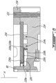
- a portion of one of the side housings, or end walls 14 is illustrated. More specifically, the portion of the end wall 14 that is shown corresponds to a portion located proximate an outer perimeter P ( Fig. 4 ) of the end wall 14 and that is configured to be in abutment against the peripheral wall 18 for defining the rotor cavity 20.
- each of the end walls 14 is configured to be secured to a respective one of opposed ends of the peripheral wall 18.
- Plates 16 are located on inner sides of the end walls 14 and define surfaces 16a on which the seals 60 of the rotor 24 are in abutment during rotation of the rotor 24.
- the end walls 14 may be made of aluminum, more specifically an aluminum alloy, due to its light weight and high thermal conductivity. However, it may be required that the surfaces of the end walls 14 in contact with the seals 60 be coated to provide a wear-resistance surface. Moreover, aluminum has high thermal coefficient of expansion and low Young's modulus, which may result in high deflections under respectively, high thermal and pressure loads.
- the plates 16 are silicon carbide plates.
- the outer body 12 that is in sealing engagement with the seals 60 of the rotor body 24 is made of silicon carbide.
- the plates 16 are thus made of a material different than a material of the peripheral wall 18 of the engine. This specific material may have the advantages of aluminum, such as high thermal conductivity combined with low density, and may lack its drawbacks, such as high thermal coefficient of expansion and low Young's modulus.
- silicon carbide's intrinsically high hardness may not require wear-resistant coating.
- the use of a silicon carbide side plate 16 provides a thermally and structurally stable running surface for the side that is also wear resistant.
- a material for the plates 16 require maximizing a ratio of the thermal conductivity to the coefficient of thermal expansion while maximizing the Young's modulus.
- heat generated by the combustion in the combustion chamber 32 is evacuated to the liquid coolant partially through the plates 16. If a heat flow through the plates 16 is insufficient, the temperature will exceed a threshold beyond which the lubricant deteriorates and impedes performance of the engine.
- the plates 16 are made thinner to increase the heat flow therethrough, they may not be stiff enough to withstand the loads imparted to the plates 16 under operation. Consequently, a balance is achieved between the thickness of the plates, the thermal conductivity of their constituent material, and their coefficient of thermal expansion.
- the plates 16 are made of silicon carbide sold by the company Kyocera under the name SC 1000.
- This type of silicon carbide has a high thermal conductivity and a low coefficient of thermal expansion as well as a high Young's modulus. Moreover, a hardness of this material is greater than that of silicon carbide coatings that may be used in other rotary engines.
- the thickness of the plates 16 ranges from 3,175 mm to 12,7 mm (1/8" to 1/2"), preferably from 3,175 mm to 9,525 mm (1/8" to 3/8"), preferably from 6,35 mm to 7,94 mm (1/4" to 5/16").
- the thickness of the plates 16 is substantially greater than that of a coating of silicon carbide, which is typically in the range of 0,254 mm to 0,381 mm (10 to 15 thousandths of an inch).
- the thickness of the plates 16 may not scale with other dimensions of the engine when increasing a size of the engine as the thermal conditions do not change with the size of the engine.
- the silicon carbide plates 16 may transmit thermal stress to the side walls 14.
- the plates 16 are mechanically unconstrained, that is floating, such that mechanical deformations imposed on it by surrounding structures might be minimized. Below is described one possible embodiment allowing the plates 16 to be mechanically unconstrained.
- the side wall 14 includes a peripheral section 14a, which is in abutment with the peripheral wall 18, and a center section 14b ( Fig. 4 ), which is circumferentially surrounded by the peripheral section 14a.
- the peripheral section 14a of the end wall 14 may be secured to the peripheral wall 18.
- the center section 14b of one of the side walls 14 faces the center section 14b of the other of the side walls 14.
- the side walls 14 are secured to the peripheral wall 18 with any suitable means known in the art.
- a sealing member 19 is located between the peripheral wall 18 and the peripheral portions 14a of the side walls 14 for limiting combustion gases from leaking out of the rotor cavity 20.
- the sealing member 19 may be a O-ring.
- the sealing member 19 may be received within an annular recess, which may be defined by one or more of the peripheral wall 18 and the end wall 14.
- the side wall 14 defines a recess 14c for receiving the plate 16.
- the peripheral portion 14a of the side wall 14 extends from the outer perimeter P to the recess 14c.
- a surface 14d of the peripheral portion 14a of the side wall 14 that faces the peripheral wall 18 is axially offset from a surface 14e of the center portion 14b of the side wall.
- a magnitude of the offset corresponds to a depth of the recess 14c and may correspond to a thickness t of the plate 16.
- the plate 16 is therefore in abutment with the surface 14e of the center portion 14b of the side wall 14.
- a sealing surface of the plate 16 located on a side of the plate 16 that faces the rotor cavity, may be aligned with the peripheral section 14a of the end wall 14.
- the side wall 14 defines an abutment surface 14f.
- the abutment surface 14f is defined by a shoulder created by the offset of the surfaces 14d, 14e of the peripheral and central portions 14a, 14b of the side wall 14.
- a gap may remain between a peripheral section of the plate 16 and the abutment surface 14f of the side wall 14.
- the plate 16 is spaced apart from the abutment surface 14f.
- a size of the gap may change during operation of the engine 10 as the side wall 14 and the plate 16 may expand at different rates with an increase of a temperature in the rotor cavity 20.
- the space between the plate 16 and the abutment surface 14f of the side wall 14 may allow relative thermal expansion between the plate 16 and the side wall 14 so that thermal stress transferred from the plate 16 to the peripheral wall 18 and the end wall 14 might be minimized.
- a periphery of the plate 16 is contained axially between the housing 18 and the side wall 14. In other words, the periphery of the plate 16 is sandwiched between the side wall 14 and the peripheral wall 18.
- a sealing member 21 is located at the periphery of the plate 16 for limiting the combustion gases to leak out of the rotor cavity 20 and for limiting the cooling fluid to leak into the combustion chamber 32 ( Fig. 1 ). As shown more specifically in Figs. 4-5 , the sealing member 21 is contained within a recess 16b defined by the plate 16.
- the sealing member 21 may be a O-ring. Any suitable sealing member may be used.
- the sealing member 21 and the abutment surface 14f of the side wall 14 allows the plate 16 to move radially relative to the side wall.
- Such a movement, along a radial direction relative to the axis of rotation of the rotor body 24, may be required in a configuration in which the side wall 14 is made of a material having a coefficient of thermal expansion different than that of the plate 16.
- the side wall 14 further defines a pocket 14g that may circumferentially extend a full circumference of the side wall 14.
- the pocket 14g is annular.
- the pocket 14g may not cover an entirety of the center portion 14b of the side wall 14.
- the pocket 14g is configured for circulating a liquid coolant, such as water for cooling the plate 16.
- the pocket 14g may be part of the fluid circuitry 12a and is in fluid flow communication with the conduits 18b that are defined in the peripheral wall 18.
- the pocket 14g extends from the surface 14e of the center portion 14b and away from the rotor cavity 20.
- a depth D of the pocket 14g is defined by a distance along the axis of rotation of the rotor body 24 between the surface 14e of the center portion 14b and a bottom surface 14h of the pocket 14g.
- the peripheral portion 14a of the side wall 14 defines a plurality of ribs 14i that are circumferentially distributed around the rotor cavity.
- the ribs 14i defines the abutment surface 14f and a portion of the surface 14e of the center portion 14b of the side wall 14. Consequently, and in the depicted embodiment, the abutment surface 14f is defined by a plurality of surfaces defined by the ribs 14i.
- the ribs 14i may be configured to support a pressure load imparted by a combustion of a mixture of air and fuel within the combustion chambers 32.
- Cavities or spaces 14j are defined between the ribs 14i. More specifically, each pair of two consecutive ones of the ribs 14i defines a space 14j therebetween.
- the spaces 14j are in fluid communication with the pocket 14g and with the conduits 18b of the peripheral wall 18. Stated otherwise, the conduits 18b are in fluid communication with the pocket 14g via the spaces 14j between the ribs 14i.
- the spaces 14j may allow the liquid coolant to flow from the pocket 14g to the conduits 18b of the peripheral wall 18. It is understood that the liquid coolant may be circulated in closed loop and through a heat exchanger.
- the heat exchanger may be used to dissipate heat to an environment outside the engine; the heat transferred from the engine to the liquid coolant.
- a flow F1 of the liquid coolant circulates within the pocket 14g.
- the flow F1 is divided in sub-flows F2; each of the sub-flows F2 circulating within a respective one of the spaces 14i and within a respective one of the conduits 18b of the coolant circuitry 12a.
- the liquid coolant may be circulated out of the outer body 12 and within a heat exchanger for extracting the heat. The liquid coolant may then be reinjected in the coolant circuitry 12a for further heat extraction.
- FIG. 6-7 another embodiment of the outer body is generally shown at 120.
- the recess 118c that receives the sealing member 21 is defined by the peripheral wall 118 instead of by the plate 116.
- FIG. 8 another embodiment of the outer body is generally shown at 220.
- bolts 221 are used to secure the peripheral wall 218 to the end walls 214.
- the end walls 214 defines a plurality of supports 214s for supporting the plates 216.
- the liquid coolant may circulate between the supports 214s.
- the plates 216 may have an epitrochoid shape and may define an aperture 216a for receiving a bearing support BS of the engine.
- a transfer housing 220 is used for sealing and centering an inner diameter of the plate 216 with respect to the peripheral wall 218.
- the transfer housing 220 may be made of an aluminum alloy.
- the transfer housing 220 is annular and extends circumferentially all around the aperture 216a of the plate 216.
- the transfer housing 220 includes a plate-engaging section 220a and an end wall-engaging section 220b connected to the plate-engaging section 220a via a connecting section 220c.
- the transfer housing 220 may have a "Z" shape when seen in cross-section.
- the plate-engaging section 220a is radially inward of the end wall-engaging section 220b relative to an axis A of the bearing support BS.
- each of the plate-engaging section 220a and the end wall-engaging section 220b defines a groove 220d for receiving a sealing member 220e, such as an O-ring.
- the sealing members 220e are used to seal an oil cavity and a cooling jacket. In other words, the sealing members 220e are used to prevent the lubricant from mixing with the liquid coolant.
- the oil cavity is located between the rotor 24 ( Fig. 1 ) and the plate 16.
- a material and dimensions of the transfer housing 220 are selected such that there are interference fits with both the end wall 214 and the plate 216. More specifically, the transfer housing 220 may be tightly fitted to the end wall 214 at the end wall-engaging section 220b and tightly fitted against a peripheral wall of the aperture 216a defined through the plate 216 at the plate-engaging section 220a. In some cases, the interference fit between the transfer housing 220 and the end wall 214 and the plate 216 is present at steady operating conditions of the engine. When the engine is starting, there may be no interference fit. The interference fit may gradually build as the engine is warming up.
- the liquid coolant may be circulated through the conduits 18b defined in the peripheral wall 18 and through the pockets 14g located between the plates 16 and the end walls 14.
- the liquid coolant is circulated from the conduits 18b in the peripheral wall 18 to the pockets 14g via the spaces 14j defined between the ribs 14i of the end walls 14.
- the liquid coolant may therefore be in direct contact with the silicon carbide plates 16 to pick up heat generated by combustion of fuel in the combustion chambers 32 ( Fig. 1 ) via conduction from the inner sides of the plates 16 that face the rotor cavity to outer sides of the plates 16 that face the pockets 14g and via convection from the outer sides of the plates 16 to the liquid coolant circulating in the pockets 14g.
- a length of a thermal path from the combustion chambers 32 to the liquid coolant may be minimized.
- a thickness of material that needs to be travelled by the heat generated by the combustion is minimized and may correspond to the thickness t of the plates 16.
- the present disclosure describes using a side housing assembly for which the side plate (seal running surface) is a silicon carbide plate.
- Silicon carbide may offer the advantages of aluminum (e.g., high thermal conductivity combined with low density) but without its drawbacks (e.g., high thermal coefficient of expansion and low Young's modulus).
- silicon carbide's intrinsically high hardness may not require wear-resistant coating.
- the use of a silicon carbide side plate may thus provide a thermally and structurally stable running surface for the side that is also wear resistant.
- the present discloses the use of silicon carbide as side seal running surface in a Wankel engine, or any other rotary engine, as well as different mechanical arrangements that may allow the use a of a side plate made of ceramic.
- the silicon carbide plate is mechanically unconstrained, that is floating, such that mechanical deformations imposed on it by surrounding structures may be minimized.
Landscapes
- Engineering & Computer Science (AREA)
- Mechanical Engineering (AREA)
- General Engineering & Computer Science (AREA)
- Cylinder Crankcases Of Internal Combustion Engines (AREA)
- Rotary Pumps (AREA)
Claims (9)
- Rotationskolbenverbrennungsmotor (10), umfassend: einen Rotor (24); ein Gehäuse, das einen Rotorhohlraum (20) umschreibt, wobei der Rotor (24) in dem Rotorhohlraum (20) aufgenommen ist, wobei das Gehäuse eine Umfangswand (18, 118, 218) und eine an der Umfangswand (18, 118, 218) befestigte Seitengehäusebaugruppe aufweist, wobei die Seitengehäusebaugruppe Platten (16, 116, 216) aufweist, die an beabstandeten Enden der Umfangswand (18, 118, 218) angeordnet sind, wobei die Platten (16, 116, 216) Dichtungslaufflächen (16a) definieren, die in dichtendem Eingriff mit gegenüberliegenden Endflächen (26) des Rotors (24) stehen, dadurch gekennzeichnet, dass:die Platten (16, 116, 216) Siliziumkarbidplatten sind;die Seitengehäusebaugruppe zwei Endwände (14, 214) beinhaltet, die an gegenüberliegenden Enden der Umfangswand (18, 118, 218) befestigt sind, wobei die Platten (16, 116, 216) an Innenseiten der Endwände (14, 214) angeordnet sind und Umfänge der Platten (16, 116, 216) zwischen den Endwänden (14, 214) und der Umfangswand (18, 118, 218) eingeklemmt sind;die Endwände (14, 214) aus einem anderen Material als die Platten (16, 116, 216) hergestellt sind; unddie Platten (16, 116, 216) schwimmen, derart, dass mechanische Verformungen, die durch umgebende Strukturen auf sie einwirken, minimiert werden.
- Rotationskolbenverbrennungsmotor nach Anspruch 1, wobei die Endwände (14, 214) an ihren Innenseiten Aussparungen (14c) definieren und die Platten (16, 116, 216) in den Aussparungen (14c) aufgenommen sind.
- Rotationskolbenverbrennungsmotor nach Anspruch 2, wobei die Endwände (14, 214) Anlageflächen (14f) an den Aussparungen (14c) definieren und in Richtung der Platten (16, 116, 216) ausgerichtet sind, wobei die Platten (16, 116, 216) von den Anlageflächen (14f) beabstandet sind.
- Rotationskolbenverbrennungsmotor nach einem der Ansprüche 1 bis 3, wobei die Seitengehäusebaugruppe Taschen (14g) zwischen den Endwänden (14, 214) und den Platten (16, 116, 216) definiert, wobei die Taschen (14g) für die Zirkulation eines flüssigen Kühlmittels konfiguriert sind.
- Rotationskolbenverbrennungsmotor nach Anspruch 4, wobei die Endwände (14, 214) eine Vielzahl von Rippen (14i) aufweisen, die in Umfangsrichtung um den Rotorhohlraum (20) verteilt ist, wobei die Taschen (14g) mit Räumen (14j) in Verbindung stehen, die zwischen den Rippen (14i) definiert sind.
- Rotationskolbenverbrennungsmotor nach Anspruch 4 oder 5, wobei die Umfangswand (18, 118, 218) Kühlmittelkanäle (18b, 118b) definiert, wobei die Kühlmittelkanäle (18b, 118b) in strömungstechnischer Verbindung mit den Taschen (14g) stehen.
- Rotationskolbenverbrennungsmotor nach einem der Ansprüche 1 bis 6, wobei Dichtungselemente (21) zwischen den Umfängen der Platten (16, 116) und der Umfangswand (18, 118) angeordnet sind.
- Rotationskolbenverbrennungsmotor nach Anspruch 7, wobei die Dichtungselemente (21) innerhalb von durch die Platten (16) definierten Aussparungen (16b) angeordnet sind.
- Rotationskolbenverbrennungsmotor nach Anspruch 7, wobei die Dichtungselemente (21) innerhalb von durch die Umfangswand (118) definierten Aussparungen (118c) angeordnet sind.
Applications Claiming Priority (2)
| Application Number | Priority Date | Filing Date | Title |
|---|---|---|---|
| US201862782454P | 2018-12-20 | 2018-12-20 | |
| US16/665,428 US11613995B2 (en) | 2018-12-20 | 2019-10-28 | Rotary engine with housing having silicon carbide plate |
Publications (2)
| Publication Number | Publication Date |
|---|---|
| EP3670833A1 EP3670833A1 (de) | 2020-06-24 |
| EP3670833B1 true EP3670833B1 (de) | 2024-06-19 |
Family
ID=69005423
Family Applications (1)
| Application Number | Title | Priority Date | Filing Date |
|---|---|---|---|
| EP19219031.2A Active EP3670833B1 (de) | 2018-12-20 | 2019-12-20 | Rotationskolbenmotor mit gehäuse mit siliziumkarbidplatte |
Country Status (5)
| Country | Link |
|---|---|
| US (1) | US11613995B2 (de) |
| EP (1) | EP3670833B1 (de) |
| CA (1) | CA3060734A1 (de) |
| ES (1) | ES2983963T3 (de) |
| PL (1) | PL3670833T3 (de) |
Families Citing this family (17)
| Publication number | Priority date | Publication date | Assignee | Title |
|---|---|---|---|---|
| US11333068B1 (en) * | 2021-03-23 | 2022-05-17 | Pratt & Whitney Canada Corp. | Side wall for rotary engine housing |
| JP7745740B2 (ja) * | 2021-07-14 | 2025-09-29 | カール アウセラー フローリアン | ロータリピストンコンプレッサ |
| US11761376B1 (en) * | 2022-11-11 | 2023-09-19 | Pratt & Whitney Canada Corp. | Side plate for rotary engine |
| US12172268B2 (en) | 2022-12-01 | 2024-12-24 | Pratt & Whitney Canada Corp. | Socket assembly for engaging a nut |
| US12123370B2 (en) * | 2023-03-08 | 2024-10-22 | Pratt & Whitney Canada Corp. | Rotary engine shim design for floating side plates |
| US12421912B2 (en) * | 2023-03-24 | 2025-09-23 | Pratt & Whitney Canada Corp. | Rotary engine with seal having elastomeric member and shield |
| US12180838B2 (en) | 2023-04-07 | 2024-12-31 | Pratt & Whitney Canada Corp. | Rotor assembly with cooling channels separated by ribs for a rotary engine |
| US12110796B1 (en) | 2023-07-13 | 2024-10-08 | Pratt & Whitney Canada Corp. | Seal assembly for a rotary engine housing |
| US12203410B1 (en) * | 2023-07-13 | 2025-01-21 | Pratt & Whitney Canada Corp. | Housing assembly for rotary engine |
| US12252991B2 (en) | 2023-07-13 | 2025-03-18 | Pratt & Whitney Canada Corp. | Seal assembly for a rotary engine housing |
| US12152490B1 (en) * | 2023-07-18 | 2024-11-26 | Pratt & Whitney Canada Corp. | Fretting resistant rotary engine housings |
| US12110819B1 (en) * | 2023-09-20 | 2024-10-08 | Pratt & Whitney Canada Corp. | Side plate for rotary engine |
| US12558747B2 (en) | 2023-09-25 | 2026-02-24 | Pratt & Whitney Canada Corp. | Method of assembling parts with different coefficients of thermal expansion |
| US12168933B1 (en) | 2023-11-17 | 2024-12-17 | Pratt & Whitney Canada Corp. | Impingement cooling assembly for an aircraft rotary engine housing |
| US12291991B1 (en) * | 2023-12-14 | 2025-05-06 | Pratt & Whitney Canada Corp. | Housing assembly for rotary engine |
| US12104550B1 (en) | 2024-01-18 | 2024-10-01 | Pratt & Whitney Canada Corp. | Rotary engine with side housing having a side plate with a ceramic matrix composite core |
| US12435661B1 (en) * | 2024-04-08 | 2025-10-07 | Pratt & Whitney Canada Corp. | Rotary engine with seal having shield and elastomeric member |
Citations (2)
| Publication number | Priority date | Publication date | Assignee | Title |
|---|---|---|---|---|
| GB2432630A (en) * | 2005-11-23 | 2007-05-30 | Paul John Worley | Near-adiabatic internal combustion rotary engine |
| US20110126795A1 (en) * | 2008-05-07 | 2011-06-02 | Shangdong Icd High Performance Fibres Co., Ltd. | Olive-shaped rotary engine |
Family Cites Families (9)
| Publication number | Priority date | Publication date | Assignee | Title |
|---|---|---|---|---|
| US3970527A (en) | 1972-12-18 | 1976-07-20 | Oxy Metal Industries Corporation | Electroformation of the running track of a rotary internal combustion engine |
| US3833320A (en) | 1973-07-05 | 1974-09-03 | Ford Motor Co | Coating for apex seals of rotary engines and method of making |
| US4259932A (en) | 1976-05-26 | 1981-04-07 | Ford Motor Company | Internal combustion engine control system |
| US4137024A (en) * | 1977-07-18 | 1979-01-30 | Curtiss-Wright Corporation | Rotor for rotary piston mechanism |
| US4782656A (en) * | 1985-03-25 | 1988-11-08 | Hansen Engine Corporation | Rotary valve assembly for engine |
| DE102008026920A1 (de) | 2007-12-01 | 2009-06-04 | Michael Dr. Fabritius | Kreiskolbenbrennkraftmaschine |
| DE102010034979A1 (de) | 2010-08-20 | 2012-02-23 | Kkm Gmbh | Kühlkreislauf in einer Kreiskolbenbrennkraftmaschine |
| US9896934B2 (en) * | 2013-12-17 | 2018-02-20 | Pratt & Whitney Canada Corp. | Rotary engine with rotor land |
| DE102016012262A1 (de) | 2016-10-13 | 2018-04-19 | Kkm Gmbh | Platten von Kreiskolbenbrennkraftmaschinen mit optimierten Oberflächen |
-
2019
- 2019-10-28 US US16/665,428 patent/US11613995B2/en active Active
- 2019-10-29 CA CA3060734A patent/CA3060734A1/en active Pending
- 2019-12-20 PL PL19219031.2T patent/PL3670833T3/pl unknown
- 2019-12-20 ES ES19219031T patent/ES2983963T3/es active Active
- 2019-12-20 EP EP19219031.2A patent/EP3670833B1/de active Active
Patent Citations (2)
| Publication number | Priority date | Publication date | Assignee | Title |
|---|---|---|---|---|
| GB2432630A (en) * | 2005-11-23 | 2007-05-30 | Paul John Worley | Near-adiabatic internal combustion rotary engine |
| US20110126795A1 (en) * | 2008-05-07 | 2011-06-02 | Shangdong Icd High Performance Fibres Co., Ltd. | Olive-shaped rotary engine |
Also Published As
| Publication number | Publication date |
|---|---|
| EP3670833A1 (de) | 2020-06-24 |
| US11613995B2 (en) | 2023-03-28 |
| PL3670833T3 (pl) | 2024-09-30 |
| US20200200009A1 (en) | 2020-06-25 |
| ES2983963T3 (es) | 2024-10-28 |
| CA3060734A1 (en) | 2020-06-20 |
Similar Documents
| Publication | Publication Date | Title |
|---|---|---|
| EP3670833B1 (de) | Rotationskolbenmotor mit gehäuse mit siliziumkarbidplatte | |
| US8336518B2 (en) | Rotary machine with roller controlled vanes | |
| US10247092B2 (en) | Rotary internal combustion engine with cooled insert | |
| US6435851B2 (en) | Vane pumping machine utilizing invar-class alloys for maximizing operating performance and reducing pollution emissions | |
| EP4435229B1 (de) | Rotationsmaschine mit dichtung mit elastomerelement und abschirmung | |
| US12196154B2 (en) | Rotary engine with seal having elastomeric and metallic members | |
| US20130028773A1 (en) | Apex seal for rotary internal combustion engine | |
| US12503975B1 (en) | Housing assembly for rotary engine and method of manufacturing thereof | |
| US12203410B1 (en) | Housing assembly for rotary engine | |
| EP4632191A1 (de) | Rotationsmaschine mit dichtung mit abschirmung und elastomerem element | |
| CA2782732C (en) | Gas seal arrangement for rotary internal combustion engine | |
| EP2642069B1 (de) | Öffnung für einen Drehverbrennungsmotor | |
| GB2332022A (en) | Rotary valve arrangement for an i.c. engine |
Legal Events
| Date | Code | Title | Description |
|---|---|---|---|
| PUAI | Public reference made under article 153(3) epc to a published international application that has entered the european phase |
Free format text: ORIGINAL CODE: 0009012 |
|
| STAA | Information on the status of an ep patent application or granted ep patent |
Free format text: STATUS: THE APPLICATION HAS BEEN PUBLISHED |
|
| AK | Designated contracting states |
Kind code of ref document: A1 Designated state(s): AL AT BE BG CH CY CZ DE DK EE ES FI FR GB GR HR HU IE IS IT LI LT LU LV MC MK MT NL NO PL PT RO RS SE SI SK SM TR |
|
| AX | Request for extension of the european patent |
Extension state: BA ME |
|
| STAA | Information on the status of an ep patent application or granted ep patent |
Free format text: STATUS: REQUEST FOR EXAMINATION WAS MADE |
|
| 17P | Request for examination filed |
Effective date: 20210111 |
|
| RBV | Designated contracting states (corrected) |
Designated state(s): AL AT BE BG CH CY CZ DE DK EE ES FI FR GB GR HR HU IE IS IT LI LT LU LV MC MK MT NL NO PL PT RO RS SE SI SK SM TR |
|
| STAA | Information on the status of an ep patent application or granted ep patent |
Free format text: STATUS: EXAMINATION IS IN PROGRESS |
|
| 17Q | First examination report despatched |
Effective date: 20211103 |
|
| GRAP | Despatch of communication of intention to grant a patent |
Free format text: ORIGINAL CODE: EPIDOSNIGR1 |
|
| STAA | Information on the status of an ep patent application or granted ep patent |
Free format text: STATUS: GRANT OF PATENT IS INTENDED |
|
| INTG | Intention to grant announced |
Effective date: 20240111 |
|
| GRAS | Grant fee paid |
Free format text: ORIGINAL CODE: EPIDOSNIGR3 |
|
| GRAA | (expected) grant |
Free format text: ORIGINAL CODE: 0009210 |
|
| STAA | Information on the status of an ep patent application or granted ep patent |
Free format text: STATUS: THE PATENT HAS BEEN GRANTED |
|
| AK | Designated contracting states |
Kind code of ref document: B1 Designated state(s): AL AT BE BG CH CY CZ DE DK EE ES FI FR GB GR HR HU IE IS IT LI LT LU LV MC MK MT NL NO PL PT RO RS SE SI SK SM TR |
|
| REG | Reference to a national code |
Ref country code: GB Ref legal event code: FG4D |
|
| REG | Reference to a national code |
Ref country code: CH Ref legal event code: EP |
|
| REG | Reference to a national code |
Ref country code: DE Ref legal event code: R096 Ref document number: 602019053840 Country of ref document: DE |
|
| PG25 | Lapsed in a contracting state [announced via postgrant information from national office to epo] |
Ref country code: BG Free format text: LAPSE BECAUSE OF FAILURE TO SUBMIT A TRANSLATION OF THE DESCRIPTION OR TO PAY THE FEE WITHIN THE PRESCRIBED TIME-LIMIT Effective date: 20240619 |
|
| PG25 | Lapsed in a contracting state [announced via postgrant information from national office to epo] |
Ref country code: HR Free format text: LAPSE BECAUSE OF FAILURE TO SUBMIT A TRANSLATION OF THE DESCRIPTION OR TO PAY THE FEE WITHIN THE PRESCRIBED TIME-LIMIT Effective date: 20240619 Ref country code: FI Free format text: LAPSE BECAUSE OF FAILURE TO SUBMIT A TRANSLATION OF THE DESCRIPTION OR TO PAY THE FEE WITHIN THE PRESCRIBED TIME-LIMIT Effective date: 20240619 |
|
| REG | Reference to a national code |
Ref country code: LT Ref legal event code: MG9D |
|
| PG25 | Lapsed in a contracting state [announced via postgrant information from national office to epo] |
Ref country code: GR Free format text: LAPSE BECAUSE OF FAILURE TO SUBMIT A TRANSLATION OF THE DESCRIPTION OR TO PAY THE FEE WITHIN THE PRESCRIBED TIME-LIMIT Effective date: 20240920 |
|
| REG | Reference to a national code |
Ref country code: NL Ref legal event code: MP Effective date: 20240619 |
|
| REG | Reference to a national code |
Ref country code: ES Ref legal event code: FG2A Ref document number: 2983963 Country of ref document: ES Kind code of ref document: T3 Effective date: 20241028 |
|
| PG25 | Lapsed in a contracting state [announced via postgrant information from national office to epo] |
Ref country code: LV Free format text: LAPSE BECAUSE OF FAILURE TO SUBMIT A TRANSLATION OF THE DESCRIPTION OR TO PAY THE FEE WITHIN THE PRESCRIBED TIME-LIMIT Effective date: 20240619 |
|
| PG25 | Lapsed in a contracting state [announced via postgrant information from national office to epo] |
Ref country code: NO Free format text: LAPSE BECAUSE OF FAILURE TO SUBMIT A TRANSLATION OF THE DESCRIPTION OR TO PAY THE FEE WITHIN THE PRESCRIBED TIME-LIMIT Effective date: 20240919 Ref country code: LV Free format text: LAPSE BECAUSE OF FAILURE TO SUBMIT A TRANSLATION OF THE DESCRIPTION OR TO PAY THE FEE WITHIN THE PRESCRIBED TIME-LIMIT Effective date: 20240619 Ref country code: HR Free format text: LAPSE BECAUSE OF FAILURE TO SUBMIT A TRANSLATION OF THE DESCRIPTION OR TO PAY THE FEE WITHIN THE PRESCRIBED TIME-LIMIT Effective date: 20240619 Ref country code: GR Free format text: LAPSE BECAUSE OF FAILURE TO SUBMIT A TRANSLATION OF THE DESCRIPTION OR TO PAY THE FEE WITHIN THE PRESCRIBED TIME-LIMIT Effective date: 20240920 Ref country code: FI Free format text: LAPSE BECAUSE OF FAILURE TO SUBMIT A TRANSLATION OF THE DESCRIPTION OR TO PAY THE FEE WITHIN THE PRESCRIBED TIME-LIMIT Effective date: 20240619 Ref country code: BG Free format text: LAPSE BECAUSE OF FAILURE TO SUBMIT A TRANSLATION OF THE DESCRIPTION OR TO PAY THE FEE WITHIN THE PRESCRIBED TIME-LIMIT Effective date: 20240619 Ref country code: RS Free format text: LAPSE BECAUSE OF FAILURE TO SUBMIT A TRANSLATION OF THE DESCRIPTION OR TO PAY THE FEE WITHIN THE PRESCRIBED TIME-LIMIT Effective date: 20240919 |
|
| PG25 | Lapsed in a contracting state [announced via postgrant information from national office to epo] |
Ref country code: NL Free format text: LAPSE BECAUSE OF FAILURE TO SUBMIT A TRANSLATION OF THE DESCRIPTION OR TO PAY THE FEE WITHIN THE PRESCRIBED TIME-LIMIT Effective date: 20240619 |
|
| PG25 | Lapsed in a contracting state [announced via postgrant information from national office to epo] |
Ref country code: NL Free format text: LAPSE BECAUSE OF FAILURE TO SUBMIT A TRANSLATION OF THE DESCRIPTION OR TO PAY THE FEE WITHIN THE PRESCRIBED TIME-LIMIT Effective date: 20240619 |
|
| PG25 | Lapsed in a contracting state [announced via postgrant information from national office to epo] |
Ref country code: PT Free format text: LAPSE BECAUSE OF FAILURE TO SUBMIT A TRANSLATION OF THE DESCRIPTION OR TO PAY THE FEE WITHIN THE PRESCRIBED TIME-LIMIT Effective date: 20241021 |
|
| PG25 | Lapsed in a contracting state [announced via postgrant information from national office to epo] |
Ref country code: PT Free format text: LAPSE BECAUSE OF FAILURE TO SUBMIT A TRANSLATION OF THE DESCRIPTION OR TO PAY THE FEE WITHIN THE PRESCRIBED TIME-LIMIT Effective date: 20241021 |
|
| PG25 | Lapsed in a contracting state [announced via postgrant information from national office to epo] |
Ref country code: EE Free format text: LAPSE BECAUSE OF FAILURE TO SUBMIT A TRANSLATION OF THE DESCRIPTION OR TO PAY THE FEE WITHIN THE PRESCRIBED TIME-LIMIT Effective date: 20240619 |
|
| PG25 | Lapsed in a contracting state [announced via postgrant information from national office to epo] |
Ref country code: IS Free format text: LAPSE BECAUSE OF FAILURE TO SUBMIT A TRANSLATION OF THE DESCRIPTION OR TO PAY THE FEE WITHIN THE PRESCRIBED TIME-LIMIT Effective date: 20241019 |
|
| PG25 | Lapsed in a contracting state [announced via postgrant information from national office to epo] |
Ref country code: RO Free format text: LAPSE BECAUSE OF FAILURE TO SUBMIT A TRANSLATION OF THE DESCRIPTION OR TO PAY THE FEE WITHIN THE PRESCRIBED TIME-LIMIT Effective date: 20240619 Ref country code: SK Free format text: LAPSE BECAUSE OF FAILURE TO SUBMIT A TRANSLATION OF THE DESCRIPTION OR TO PAY THE FEE WITHIN THE PRESCRIBED TIME-LIMIT Effective date: 20240619 |
|
| PG25 | Lapsed in a contracting state [announced via postgrant information from national office to epo] |
Ref country code: SM Free format text: LAPSE BECAUSE OF FAILURE TO SUBMIT A TRANSLATION OF THE DESCRIPTION OR TO PAY THE FEE WITHIN THE PRESCRIBED TIME-LIMIT Effective date: 20240619 |
|
| PG25 | Lapsed in a contracting state [announced via postgrant information from national office to epo] |
Ref country code: SM Free format text: LAPSE BECAUSE OF FAILURE TO SUBMIT A TRANSLATION OF THE DESCRIPTION OR TO PAY THE FEE WITHIN THE PRESCRIBED TIME-LIMIT Effective date: 20240619 Ref country code: SK Free format text: LAPSE BECAUSE OF FAILURE TO SUBMIT A TRANSLATION OF THE DESCRIPTION OR TO PAY THE FEE WITHIN THE PRESCRIBED TIME-LIMIT Effective date: 20240619 Ref country code: RO Free format text: LAPSE BECAUSE OF FAILURE TO SUBMIT A TRANSLATION OF THE DESCRIPTION OR TO PAY THE FEE WITHIN THE PRESCRIBED TIME-LIMIT Effective date: 20240619 Ref country code: IS Free format text: LAPSE BECAUSE OF FAILURE TO SUBMIT A TRANSLATION OF THE DESCRIPTION OR TO PAY THE FEE WITHIN THE PRESCRIBED TIME-LIMIT Effective date: 20241019 Ref country code: EE Free format text: LAPSE BECAUSE OF FAILURE TO SUBMIT A TRANSLATION OF THE DESCRIPTION OR TO PAY THE FEE WITHIN THE PRESCRIBED TIME-LIMIT Effective date: 20240619 |
|
| REG | Reference to a national code |
Ref country code: DE Ref legal event code: R097 Ref document number: 602019053840 Country of ref document: DE |
|
| PG25 | Lapsed in a contracting state [announced via postgrant information from national office to epo] |
Ref country code: DK Free format text: LAPSE BECAUSE OF FAILURE TO SUBMIT A TRANSLATION OF THE DESCRIPTION OR TO PAY THE FEE WITHIN THE PRESCRIBED TIME-LIMIT Effective date: 20240619 |
|
| PLBE | No opposition filed within time limit |
Free format text: ORIGINAL CODE: 0009261 |
|
| STAA | Information on the status of an ep patent application or granted ep patent |
Free format text: STATUS: NO OPPOSITION FILED WITHIN TIME LIMIT |
|
| 26N | No opposition filed |
Effective date: 20250320 |
|
| PG25 | Lapsed in a contracting state [announced via postgrant information from national office to epo] |
Ref country code: MC Free format text: LAPSE BECAUSE OF FAILURE TO SUBMIT A TRANSLATION OF THE DESCRIPTION OR TO PAY THE FEE WITHIN THE PRESCRIBED TIME-LIMIT Effective date: 20240619 |
|
| PG25 | Lapsed in a contracting state [announced via postgrant information from national office to epo] |
Ref country code: LU Free format text: LAPSE BECAUSE OF NON-PAYMENT OF DUE FEES Effective date: 20241220 |
|
| PG25 | Lapsed in a contracting state [announced via postgrant information from national office to epo] |
Ref country code: SE Free format text: LAPSE BECAUSE OF FAILURE TO SUBMIT A TRANSLATION OF THE DESCRIPTION OR TO PAY THE FEE WITHIN THE PRESCRIBED TIME-LIMIT Effective date: 20240619 |
|
| REG | Reference to a national code |
Ref country code: BE Ref legal event code: MM Effective date: 20241231 |
|
| REG | Reference to a national code |
Ref country code: AT Ref legal event code: UEP Ref document number: 1696027 Country of ref document: AT Kind code of ref document: T Effective date: 20240619 |
|
| PG25 | Lapsed in a contracting state [announced via postgrant information from national office to epo] |
Ref country code: BE Free format text: LAPSE BECAUSE OF NON-PAYMENT OF DUE FEES Effective date: 20241231 |
|
| PG25 | Lapsed in a contracting state [announced via postgrant information from national office to epo] |
Ref country code: IE Free format text: LAPSE BECAUSE OF NON-PAYMENT OF DUE FEES Effective date: 20241220 |
|
| REG | Reference to a national code |
Ref country code: CH Ref legal event code: U11 Free format text: ST27 STATUS EVENT CODE: U-0-0-U10-U11 (AS PROVIDED BY THE NATIONAL OFFICE) Effective date: 20260101 |
|
| PGFP | Annual fee paid to national office [announced via postgrant information from national office to epo] |
Ref country code: DE Payment date: 20251126 Year of fee payment: 7 |
|
| PGFP | Annual fee paid to national office [announced via postgrant information from national office to epo] |
Ref country code: GB Payment date: 20251120 Year of fee payment: 7 |
|
| PGFP | Annual fee paid to national office [announced via postgrant information from national office to epo] |
Ref country code: AT Payment date: 20251121 Year of fee payment: 7 |
|
| PGFP | Annual fee paid to national office [announced via postgrant information from national office to epo] |
Ref country code: IT Payment date: 20251119 Year of fee payment: 7 |
|
| PGFP | Annual fee paid to national office [announced via postgrant information from national office to epo] |
Ref country code: FR Payment date: 20251120 Year of fee payment: 7 |
|
| PGFP | Annual fee paid to national office [announced via postgrant information from national office to epo] |
Ref country code: CZ Payment date: 20251211 Year of fee payment: 7 |
|
| PGFP | Annual fee paid to national office [announced via postgrant information from national office to epo] |
Ref country code: PL Payment date: 20251120 Year of fee payment: 7 |
|
| PGFP | Annual fee paid to national office [announced via postgrant information from national office to epo] |
Ref country code: ES Payment date: 20260102 Year of fee payment: 7 |
|
| PGFP | Annual fee paid to national office [announced via postgrant information from national office to epo] |
Ref country code: CH Payment date: 20260101 Year of fee payment: 7 |