EP3670863B1 - Hilfsschmiersystem mit durchflussverwaltungsventil - Google Patents
Hilfsschmiersystem mit durchflussverwaltungsventil Download PDFInfo
- Publication number
- EP3670863B1 EP3670863B1 EP19204350.3A EP19204350A EP3670863B1 EP 3670863 B1 EP3670863 B1 EP 3670863B1 EP 19204350 A EP19204350 A EP 19204350A EP 3670863 B1 EP3670863 B1 EP 3670863B1
- Authority
- EP
- European Patent Office
- Prior art keywords
- lubricant
- starvation
- pump
- lubrication system
- component
- Prior art date
- Legal status (The legal status is an assumption and is not a legal conclusion. Google has not performed a legal analysis and makes no representation as to the accuracy of the status listed.)
- Active
Links
Images


Classifications
-
- F—MECHANICAL ENGINEERING; LIGHTING; HEATING; WEAPONS; BLASTING
- F02—COMBUSTION ENGINES; HOT-GAS OR COMBUSTION-PRODUCT ENGINE PLANTS
- F02C—GAS-TURBINE PLANTS; AIR INTAKES FOR JET-PROPULSION PLANTS; CONTROLLING FUEL SUPPLY IN AIR-BREATHING JET-PROPULSION PLANTS
- F02C7/00—Features, components parts, details or accessories, not provided for in, or of interest apart form groups F02C1/00 - F02C6/00; Air intakes for jet-propulsion plants
- F02C7/06—Arrangements of bearings; Lubricating
-
- F—MECHANICAL ENGINEERING; LIGHTING; HEATING; WEAPONS; BLASTING
- F01—MACHINES OR ENGINES IN GENERAL; ENGINE PLANTS IN GENERAL; STEAM ENGINES
- F01D—NON-POSITIVE DISPLACEMENT MACHINES OR ENGINES, e.g. STEAM TURBINES
- F01D25/00—Component parts, details, or accessories, not provided for in, or of interest apart from, other groups
- F01D25/18—Lubricating arrangements
- F01D25/20—Lubricating arrangements using lubrication pumps
-
- F—MECHANICAL ENGINEERING; LIGHTING; HEATING; WEAPONS; BLASTING
- F01—MACHINES OR ENGINES IN GENERAL; ENGINE PLANTS IN GENERAL; STEAM ENGINES
- F01M—LUBRICATING OF MACHINES OR ENGINES IN GENERAL; LUBRICATING INTERNAL COMBUSTION ENGINES; CRANKCASE VENTILATING
- F01M11/00—Component parts, details or accessories, not provided for in, or of interest apart from, groups F01M1/00 - F01M9/00
- F01M11/06—Means for keeping lubricant level constant or for accommodating movement or position of machines or engines
- F01M11/062—Accommodating movement or position of machines or engines, e.g. dry sumps
- F01M11/065—Position
- F01M11/067—Position inverted, e.g. for inverted flight
-
- F—MECHANICAL ENGINEERING; LIGHTING; HEATING; WEAPONS; BLASTING
- F01—MACHINES OR ENGINES IN GENERAL; ENGINE PLANTS IN GENERAL; STEAM ENGINES
- F01M—LUBRICATING OF MACHINES OR ENGINES IN GENERAL; LUBRICATING INTERNAL COMBUSTION ENGINES; CRANKCASE VENTILATING
- F01M1/00—Pressure lubrication
- F01M1/12—Closed-circuit lubricating systems not provided for in groups F01M1/02 - F01M1/10
- F01M2001/123—Closed-circuit lubricating systems not provided for in groups F01M1/02 - F01M1/10 using two or more pumps
-
- F—MECHANICAL ENGINEERING; LIGHTING; HEATING; WEAPONS; BLASTING
- F05—INDEXING SCHEMES RELATING TO ENGINES OR PUMPS IN VARIOUS SUBCLASSES OF CLASSES F01-F04
- F05D—INDEXING SCHEME FOR ASPECTS RELATING TO NON-POSITIVE-DISPLACEMENT MACHINES OR ENGINES, GAS-TURBINES OR JET-PROPULSION PLANTS
- F05D2260/00—Function
- F05D2260/40—Transmission of power
- F05D2260/403—Transmission of power through the shape of the drive components
- F05D2260/4031—Transmission of power through the shape of the drive components as in toothed gearing
- F05D2260/40311—Transmission of power through the shape of the drive components as in toothed gearing of the epicyclical, planetary or differential type
-
- F—MECHANICAL ENGINEERING; LIGHTING; HEATING; WEAPONS; BLASTING
- F05—INDEXING SCHEMES RELATING TO ENGINES OR PUMPS IN VARIOUS SUBCLASSES OF CLASSES F01-F04
- F05D—INDEXING SCHEME FOR ASPECTS RELATING TO NON-POSITIVE-DISPLACEMENT MACHINES OR ENGINES, GAS-TURBINES OR JET-PROPULSION PLANTS
- F05D2260/00—Function
- F05D2260/98—Lubrication
-
- F—MECHANICAL ENGINEERING; LIGHTING; HEATING; WEAPONS; BLASTING
- F05—INDEXING SCHEMES RELATING TO ENGINES OR PUMPS IN VARIOUS SUBCLASSES OF CLASSES F01-F04
- F05D—INDEXING SCHEME FOR ASPECTS RELATING TO NON-POSITIVE-DISPLACEMENT MACHINES OR ENGINES, GAS-TURBINES OR JET-PROPULSION PLANTS
- F05D2270/00—Control
- F05D2270/30—Control parameters, e.g. input parameters
- F05D2270/301—Pressure
-
- F—MECHANICAL ENGINEERING; LIGHTING; HEATING; WEAPONS; BLASTING
- F16—ENGINEERING ELEMENTS AND UNITS; GENERAL MEASURES FOR PRODUCING AND MAINTAINING EFFECTIVE FUNCTIONING OF MACHINES OR INSTALLATIONS; THERMAL INSULATION IN GENERAL
- F16N—LUBRICATING
- F16N2210/00—Applications
- F16N2210/02—Turbines
Definitions
- the present disclosure relates to gas turbine engines and, more particularly, to lubrication systems used in gas turbine engine compressors.
- Gas turbine engines typically include a fan section, a compressor section, a combustor section and a turbine section. During operation, air is pressurized in the compressor section and mixed with fuel and burned in the combustor section to generate hot combustion gases. The hot combustion gases are then communicated through the turbine section, which extracts energy from the hot combustion gases to power the compressor section, the fan section and various other loads occurring within or proximate a gas turbine engine.
- a main pump is typically driven by a high pressure spool, connected through gearing, and is used to pump lubricating fluid to all such engine components, including, for example, rolling element bearings, gear teeth, carbon seals, and journal bearings for supporting gears.
- the main pump typically pumps fluid from a passage connected to a main reservoir that holds both liquid and air. During normal operating conditions, the fluid settles at the bottom of the main reservoir and displaces air to the top. However, in a gas turbine engine mounted on an aircraft, the main reservoir may experience "negative gravity" conditions (or a negative gravity event) such as the aircraft turning upside down, the aircraft accelerating toward the Earth at a rate equal to or greater than the rate of gravity, or the aircraft decelerating at the end of a vertical ascent.
- the fluid in the main reservoir can rise to the top, which can expose an opening of the passage to air and interrupt the supply of fluid to the main pump and, consequently, interrupt the supply of fluid to the engine components requiring lubrication.
- the fluid may also rise to the tops of individual component compartments, thereby preventing the fluid within the individual component compartments from being scavenged back to the main reservoir.
- Certain engine components such as carbon seals used in the compressor and turbine sections, are relatively intolerant to lubricant starvation and can be damaged by short periods of non-lubricating operation during negative gravity conditions.
- Other components such as rolling element bearings or drive gears, may exhibit greater tolerance for lubricant starvation. In the more extreme situations, the starvation intolerant components may be rendered inoperative.
- US 2013/318939A1 discloses an apparatus for supplying lubricant to a gear assembly in a gas turbine engine including a valve having a valve inlet configured to be coupled to a source of lubricant.
- EP 1 925 856 A2 discloses a lubrication system including an auxiliary lubricant tank, a supply conduit extending from a source of lubricant to the auxiliary lubricant tank.
- a lubrication system as claimed in claim 1 is disclosed.
- a boost pump is configured to receive the lubricant from the main pump and to pump the lubricant to the starvation intolerant component.
- a scavenge pump is configured to receive the lubricant from the starvation intolerant component and the starvation tolerant component.
- the scavenge pump is configured to pump the lubricant to the storage tank.
- the bias mechanism is configured to be responsive to a fluid pressure within the lubrication system. In various embodiments, the bias mechanism is configured to be responsive to a fluid pressure in a scavenge pump exit conduit.
- the flow management valve includes a two-way valve configured to direct the lubricant to the starvation tolerant component during a normal operation state and to the valve exit conduit during a non-normal operation state.
- the flow management valve is configured to be responsive to a pressure sensor configured to detect at least one of the normal operation state and the non-normal operation state.
- the pressure sensor is configured to detect a fluid pressure downstream of the main pump and upstream of the flow management valve.
- the valve exit conduit is configured to direct the lubricant to the main pump during the non-normal operation state.
- the gas turbine engine further includes a boost pump configured to receive the lubricant from the main pump and to pump the lubricant to the one or more starvation intolerant components and a scavenge pump configured to receive the lubricant from the one or more starvation intolerant components and the one or more starvation tolerant components.
- a boost pump configured to receive the lubricant from the main pump and to pump the lubricant to the one or more starvation intolerant components
- a scavenge pump configured to receive the lubricant from the one or more starvation intolerant components and the one or more starvation tolerant components.
- the make-up reservoir is configured to provide a make-up volume of the lubricant to the lubrication system during a negative gravity event. In various embodiments, the make-up reservoir is configured to adjust a volume of the lubricant within the make-up reservoir between a normal operation volume and a negative gravity event volume.
- the flow management valve includes a two-way valve configured to direct the lubricant to the one or more starvation tolerant components during a normal operation state and to the main pump during a negative gravity event.
- the flow management valve is configured to be responsive to a pressure sensor configured to detect at least one of the normal operation state and the negative gravity event.
- references to "a,” “an” or “the” may include one or more than one and that reference to an item in the singular may also include the item in the plural. Further, all ranges may include upper and lower values and all ranges and ratio limits disclosed herein may be combined.
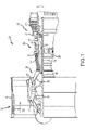
- FIG. 1 schematically illustrates a gas turbine engine 20.
- the gas turbine engine 20 is disclosed herein as a two-spool turbofan that generally incorporates a fan section 22, a compressor section 24, a combustor section 26 and a turbine section 28.
- the fan section 22 drives air along a bypass flow path B in a bypass duct defined within a nacelle 15, while the compressor section 24 drives air along a primary or core flow path C for compression and communication into the combustor section 26 and then expansion through the turbine section 28.
- the gas turbine engine 20 generally includes a low speed spool 30 and a high speed spool 32 mounted for rotation about an engine central longitudinal axis A relative to an engine static structure 36 via several bearing systems 38. It should be understood that various bearing systems at various locations may alternatively or additionally be provided and the location of the several bearing systems 38 may be varied as appropriate to the application.
- the low speed spool 30 generally includes an inner shaft 40 that interconnects a fan 42, a low pressure compressor 44 and a low pressure turbine 46.
- the inner shaft 40 is connected to the fan 42 through a speed change mechanism, which in this gas turbine engine 20 is illustrated as a fan drive gear system 48 configured to drive the fan 42 at a lower speed than the low speed spool 30.
- the high speed spool 32 includes an outer shaft 50 that interconnects a high pressure compressor 52 and a high pressure turbine 54.
- a combustor 56 is arranged in the gas turbine engine 20 between the high pressure compressor 52 and the high pressure turbine 54.
- a mid-turbine frame 57 of the engine static structure 36 is arranged generally between the high pressure turbine 54 and the low pressure turbine 46 and may include airfoils 59 in the core flow path C for guiding the flow into the low pressure turbine 46.
- the mid-turbine frame 57 further supports the several bearing systems 38 in the turbine section 28.
- the inner shaft 40 and the outer shaft 50 are concentric and rotate via the several bearing systems 38 about the engine central longitudinal axis A, which is collinear with longitudinal axes of the inner shaft 40 and the outer shaft 50.
- the air in the core flow path C is compressed by the low pressure compressor 44 and then the high pressure compressor 52, mixed and burned with fuel in the combustor 56, and then expanded over the high pressure turbine 54 and low pressure turbine 46.
- the low pressure turbine 46 and the high pressure turbine 54 rotationally drive the respective low speed spool 30 and the high speed spool 32 in response to the expansion.
- each of the positions of the fan section 22, the compressor section 24, the combustor section 26, the turbine section 28, and the fan drive gear system 48 may be varied.
- the fan drive gear system 48 may be located aft of the combustor section 26 or even aft of the turbine section 28, and the fan section 22 may be positioned forward or aft of the location of the fan drive gear system 48.
- a lubrication system 200 is configured to cycle a lubricant to and from one or more engine components (e.g., bearings, seals and drive gears) of a gas turbine engine, such as, for example, the gas turbine engine 20 described above with reference to FIG. 1 .
- engine components e.g., bearings, seals and drive gears
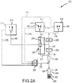
- the lubrication system 200 may include a lubricant storage tank 202 for storing a quantity of lubricant and may include a main pump 204 for drawing a supply of lubricant from the lubricant storage tank 202 and passing that lubricant to the one or more engine components, which include, for example, a first starvation intolerant component 206, a second starvation intolerant component 208 and a starvation tolerant component 210.
- the first starvation intolerant component 206 may comprise a first seal 212
- the second starvation intolerant component 208 may comprise a second seal 214
- the starvation tolerant component 210 may comprise a rolling element bearing 216.
- starvation intolerant components to include any component that is intolerant to interruptions to the supply of lubrication fluid and starvation tolerant components to include any component that is not intolerant to interruptions to the supply of lubrication fluid.
- the lubrication system 200 may also include a boost pump 218 for drawing a supply of lubricant from a main pump exit conduit 220 of the main pump 204 and passing that lubricant to one or more starvation intolerant engine components, which include, for example, the first starvation intolerant component 206 and the second starvation intolerant component 208.
- the lubrication system 200 further includes a scavenge pump 222.
- the scavenge pump 222 receives lubricant from one or more starvation tolerant components, including, for example, the first starvation intolerant component 206 and the second starvation intolerant component 208, by one or more starvation intolerant component return conduits 224.
- the scavenge pump 222 is configured to receive lubricant from one or more starvation tolerant components, including, for example, the starvation tolerant component 210, by one or more starvation tolerant component return conduits 226.
- the scavenge pump 222 comprises multiple stages, each of which includes its own inlet and is dedicated to a particular component or a compartment of such particular component.
- the lubrication system 200 further includes a make-up reservoir 228 that may act as an accumulator. As described further below, the make-up reservoir 228 is configured to receive lubricant from a scavenge pump exit conduit 230 and to discharge lubricant into the scavenge pump exit conduit 230, depending on the pressure within the scavenge pump exit conduit 230.
- the lubrication system 200 further includes one or more components configured to permit or prevent fluid flow to the one or more starvation tolerant components, including, for example, the starvation tolerant component 210, depending on whether a negative gravity event or similar situation is being experienced.
- the lubrication system 200 includes an oil flow management valve 232 that is configured to permit the flow of lubricant to the starvation tolerant component 210 during normal operation (see FIG. 2A ) and to prevent the flow of lubricant to the starvation tolerant component 210 during a negative gravity event or similar situation (see FIG. 2B ).
- the oil flow management valve 232 may include a pressure sensor 234 configured to sense the fluid pressure within the main pump exit conduit 220 of the main pump 204.
- the pressure sensor 234 is configured to operate a two-way valve 236 within the oil flow management valve 232, such that lubricant flows to the starvation tolerant component 210 during normal operation and to a main pump inlet conduit 238 during a negative gravity event.
- the oil flow management valve 232 receives lubricant from the main pump exit conduit 220.
- the pressure sensor 234 detects a normal operating pressure within the main pump exit conduit 220 and, in response, directs the lubricant flowing into the oil flow management valve 232 to the one or more starvation tolerant components, including the starvation tolerant component 210, through one or more starvation tolerant component inlet conduits 240.
- lubricant in the main pump exit conduit 220 is fed to the boost pump 218 for supply to the one or more starvation intolerant components, including the first starvation intolerant component 206 and the second starvation intolerant component 208, through one or more starvation intolerant component inlet conduits 242.
- lubricant flows, for example, to each of the first starvation intolerant component 206, the second starvation intolerant component 208 and the starvation tolerant component 210.
- the fluid pumped to each of the components exits one or more nozzles 244 to lubricate the respective component, collects within a component housing 246 and returns to the scavenge pump 222 via component return conduits, such as, for example, the one or more starvation intolerant component return conduits 224 and the one or more starvation tolerant component return conduits 226.
- component return conduits such as, for example, the one or more starvation intolerant component return conduits 224 and the one or more starvation tolerant component return conduits 226.
- the oil flow management valve 232 still receives lubricant from the main pump exit conduit 220.
- the pressure sensor 23 detects a drop in pressure within the main pump exit conduit 220 and, in response, directs the lubricant flowing into the oil flow management valve 232 to a valve exit conduit 248 configured to route the lubricant back to the main pump inlet conduit 238, thereby shutting off the flow of lubricant to the one or more starvation tolerant components, including the starvation tolerant component 210.
- lubricant in the main pump exit conduit 220 is still fed to the boost pump 218 for supply to the one or more starvation intolerant components, including the first starvation intolerant component 206 and the second starvation intolerant component 208, through one or more starvation intolerant component inlet conduits 242.
- lubricant flows, for example, only to each of the first starvation intolerant component 206 and the second starvation intolerant component 208, with no fluid flowing to the starvation tolerant component 210.
- the flow management valve 232 may still be configured to reduce flow of lubricant to the starvation intolerant components to an amount sufficient to match a specific need to such components and to efficiently use the available lubricant volume to maximize the oil supply duration during such negative gravity event.
- lubricant within the lubricant storage tank 202 or the component housing 246 associated with each of the one or more tolerant and intolerant components may collect at locations that prevent or restrict the lubricant from flowing to the main pump 204 or to the scavenge pump 222, respectively. This occurrence may result in a temporary shortage of lubricant and an attendant drop in pressure in the various conduits of the lubrication system 200, including the scavenge pump exit conduit 230 and the main pump exit conduit 220.
- the oil flow management valve 232 detects the drop in pressure and effectively shuts down a part of the lubrication system 200 - e.g., the part of the system feeding lubricant to the one or more starvation tolerant components. This reduces the need for lubricant to make up for the shortage of lubricant, but may not be sufficient in and of itself. Accordingly, in various embodiments, the reduced pressure in the scavenge pump exit conduit 230 results in an influx of lubricant from the make-up reservoir 228 to make up for any remaining shortage of lubricant.
- oil flow management valve 232 is configured to detect the drop in pressure
- disclosure contemplates such detection also be accomplished through engine control systems configured to monitor lubricant pressures at various locations throughout the lubrication system 200 or one or more of such lubricant pressures and attitudes or accelerations or like parameters of the aircraft or its motion, to determine when the oil flow management valve 232 should be closed or opened.
- the make-up reservoir 228 includes a chamber 250 defined, in part, by a piston 252 at one end.
- the piston 252 is operated by a bias mechanism which, for example, may comprise a coil spring 254.
- a bias mechanism which, for example, may comprise a coil spring 254.
- the bias mechanism is tuned to allow the chamber 250 to expand during normal operation to a normal operation volume 256, as illustrated in FIG. 2A .
- the bias mechanism responds to the drop in pressure by urging the piston 252 into the chamber 250, thereby reducing the normal operation volume to a negative gravity event volume and, consequently, pumping lubricant into the scavenge pump exit conduit 230 and into the lubricant storage tank 202.
- the negative gravity event volume may, in various embodiments, depend on the severity of the negative gravity event but, in any case, is sufficient to provide excess lubricant in an amount sufficient to make up for the shortage of lubricant (e.g., a make-up volume of lubricant).
- the lubricant e.g., the make-up volume of lubricant
- a method 300 of selectively supplying a lubricant to a starvation tolerant component of a gas turbine engine includes operating a main pump configured to receive the lubricant from a storage tank and to pump the lubricant to a flow management valve and to a starvation intolerant component.
- a negative gravity event is detected in a second step 304.
- a third step 306 of the method includes causing the flow management valve to terminate delivery of the lubricant to a starvation tolerant component and to reroute the lubricant to supply the main pump.
- the method 300 further includes operating a make-up reservoir to provide a make-up volume of the lubricant to the main pump.
- references to "one embodiment,” “an embodiment,” “various embodiments,” etc. indicate that the embodiment described may include a particular feature, structure, or characteristic, but every embodiment may not necessarily include the particular feature, structure, or characteristic. Moreover, such phrases are not necessarily referring to the same embodiment. Further, when a particular feature, structure, or characteristic is described in connection with an embodiment, it is submitted that it is within the knowledge of one skilled in the art to affect such feature, structure, or characteristic in connection with other embodiments whether or not explicitly described. After reading the description, it will be apparent to one skilled in the relevant art(s) how to implement the disclosure in alternative embodiments.
- the terms "comprises,” “comprising,” or any other variation thereof, are intended to cover a non-exclusive inclusion, such that a process, method, article, or apparatus that comprises a list of elements does not include only those elements but may include other elements not expressly listed or inherent to such process, method, article, or apparatus.
Landscapes
- Engineering & Computer Science (AREA)
- Mechanical Engineering (AREA)
- General Engineering & Computer Science (AREA)
- Chemical & Material Sciences (AREA)
- Combustion & Propulsion (AREA)
- Lubrication Of Internal Combustion Engines (AREA)
Claims (15)
- Schmiersystem (200), umfassend:einen Speichertank (202), der dazu konfiguriert ist, ein Schmiermittel zu speichern;ein Durchflussregelungsventil (232), das dazu konfiguriert ist, das Schmiermittel zu einem mangeltoleranten Bauteil (210) und zu einer Ventilausgangsleitung (248) zu leiten; undeine Hauptpumpe (204), die dazu konfiguriert ist, das Schmiermittel von dem Speichertank (202) aufzunehmen und das Schmiermittel zum Durchflussregelungsventil (232) und zu einem nicht mangeltoleranten Bauteil (206, 208) zu pumpen,gekennzeichnet durch einen Zusatzbehälter (228) in Fluidverbindung mit dem Speichertank (202), wobei der Zusatzbehälter (228) eine Kammer (250), einen Kolben (252), einen Vorspannmechanismus, der dazu konfiguriert ist, ein Volumen des Schmiermittels innerhalb der Kammer (250) anzupassen, beinhaltet.
- Schmiersystem nach Anspruch 1, ferner eine Förderpumpe (218) umfassend, die dazu konfiguriert ist, das Schmiermittel von der Hauptpumpe (204) aufzunehmen und das Schmiermittel zu dem nicht mangeltoleranten Bauteil (206, 208) zu pumpen.
- Schmiersystem nach Anspruch 2, ferner eine Rückförderpumpe (222) umfassend, die dazu konfiguriert ist, das Schmiermittel von dem nicht mangeltoleranten Bauteil (206, 208) und dem mangeltoleranten Bauteil (210) aufzunehmen.
- Schmiersystem nach Anspruch 3, wobei die Rückförderpumpe (222) dazu konfiguriert ist, das Schmiermittel zu dem Speichertank (202) zu pumpen.
- Schmiersystem nach einem vorhergehenden Anspruch, wobei der Vorspannmechanismus dazu konfiguriert ist, auf einen Fluiddruck innerhalb des Schmiersystems (200) anzusprechen, oder
wobei der Vorspannmechanismus dazu konfiguriert ist, auf einen Fluiddruck in einer Rückförderpumpenausgangsleitung (230) anzusprechen. - Schmiersystem nach einem vorhergehenden Anspruch, wobei das Durchflussregelungsventil (232) ein Zweiwegeventil (236) enthält, das dazu konfiguriert ist, das Schmiermittel während eines normalen Betriebszustands zu dem mangeltoleranten Bauteil (210) und während eines nicht normalen Betriebszustands zur Ventilausgangsleitung (248) zu leiten.
- Schmiersystem nach Anspruch 6, wobei das Durchflussregelungsventil (232) dazu konfiguriert ist, auf einen Drucksensor (234) anzusprechen, der dazu konfiguriert ist, mindestens einen von dem normalen Betriebszustand und dem nicht normalen Betriebszustand zu erkennen.
- Schmiersystem nach Anspruch 7, wobei der Drucksensor (234) dazu konfiguriert ist, einen Fluiddruck stromabwärts der Hauptpumpe (204) und stromaufwärts des Durchflussregelungsventils (232) zu erkennen.
- Schmiersystem nach einem der Ansprüche 6, 7 oder 8, wobei die Ventilausgangsleitung (248) dazu konfiguriert ist, das Schmiermittel während des nicht normalen Betriebszustands zu der Hauptpumpe (204) zu leiten.
- Gasturbinentriebwerk (20), umfassend:ein oder mehrere mangeltolerante Bauteile (210);ein oder mehrere nicht mangeltolerante Bauteile (206, 208); unddas Schmiersystem (200) nach Anspruch 1,wobei das Durchflussregelungsventil (232) dazu konfiguriert ist,das Schmiermittel selektiv zu dem einen oder den mehreren mangeltoleranten Bauteilen (210) zu leiten, unddie Hauptpumpe dazu konfiguriert ist, das Schmiermittel von dem Speichertank aufzunehmen und das Schmiermittel zu dem Durchflussregelungsventil und zu dem einen oder den mehreren nicht mangeltoleranten Bauteilen zu pumpen.
- Gasturbinentriebwerk nach Anspruch 10, ferner eine Förderpumpe (218) umfassend, die dazu konfiguriert ist, das Schmiermittel von der Hauptpumpe (204) aufzunehmen und das Schmiermittel zu dem einen oder den mehreren nicht mangeltoleranten Bauteilen (206, 208) und einer Rückförderpumpe (222) zu pumpen, die dazu konfiguriert ist, das Schmiermittel von dem einen oder den mehreren nicht mangeltoleranten Bauteilen (206, 208) und dem einen oder den mehreren mangeltoleranten Bauteilen (210) aufzunehmen.
- Gasturbinentriebwerk nach Anspruch 10 oder 11, wobei der Zusatzbehälter (228) dazu konfiguriert ist, ein Zusatzvolumen des Schmiermittels dem Schmiersystem (200) während eines negativen Schwerkraftereignisses bereitzustellen.
- Gasturbinentriebwerk nach Anspruch 10, 11 oder 12, wobei der Zusatzbehälter (228) dazu konfiguriert ist, ein Volumen des Schmiermittels innerhalb des Zusatzbehälters (228) zwischen einem normalen Betriebsvolumen (256) und einem Volumen bei einem negativen Schwerkraftereignis anzupassen.
- Gasturbinentriebwerk nach einem der Ansprüche 10 bis 13, wobei das Durchflussregelungsventil (232) ein Zweiwegeventil (236) enthält, das dazu konfiguriert ist, das Schmiermittel während eines normalen Betriebszustands zu dem einen oder den mehreren mangeltoleranten Bauteilen (210) und zur Hauptpumpe (204) während eines negativen Schwerkraftereignisses zu leiten, wobei optional das Durchflussregelungsventil (232) dazu konfiguriert ist, auf einen Drucksensor (234) anzusprechen, der dazu konfiguriert ist, mindestens einen von dem normalen Betriebszustand und dem negativen Schwerkraftereignis zu erkennen.
- Verfahren zum selektiven Liefern eines Schmiermittels zu einem mangeltoleranten Bauteil (210) eines Gasturbinentriebwerks (20), umfassend:Betreiben einer Hauptpumpe (204), die dazu konfiguriert ist, das Schmiermittel von einem Speichertank (202) aufzunehmen und das Schmiermittel zu einem Durchflussregelungsventil (232) und zu einem nicht mangeltoleranten Bauteil (206, 208) zu pumpen;Erkennen eines negativen Schwerkraftereignisses; undBewirken, dass das Durchflussregelungsventil (232) die Zufuhr des Schmiermittels zu dem mangeltoleranten Bauteil (210) beendet und das Schmiermittel umleitet, um die Hauptpumpe (204) zu versorgen,gekennzeichnet durch Betreiben eines Zusatzbehälters (228), um ein Zusatzvolumen des Schmiermittels der Hauptpumpe (204) bereitzustellen, wobei der Zusatzbehälter (228) eine Kammer (250), einen Kolben (252) und einen Vorspannmechanismus umfasst, der dazu konfiguriert ist, das Zusatzvolumen des Schmiermittels innerhalb der Kammer (250) anzupassen.
Applications Claiming Priority (1)
| Application Number | Priority Date | Filing Date | Title |
|---|---|---|---|
| US16/230,711 US11236637B2 (en) | 2018-12-21 | 2018-12-21 | Auxiliary lubrication system with flow management valve |
Publications (2)
| Publication Number | Publication Date |
|---|---|
| EP3670863A1 EP3670863A1 (de) | 2020-06-24 |
| EP3670863B1 true EP3670863B1 (de) | 2022-08-03 |
Family
ID=68296269
Family Applications (1)
| Application Number | Title | Priority Date | Filing Date |
|---|---|---|---|
| EP19204350.3A Active EP3670863B1 (de) | 2018-12-21 | 2019-10-21 | Hilfsschmiersystem mit durchflussverwaltungsventil |
Country Status (2)
| Country | Link |
|---|---|
| US (1) | US11236637B2 (de) |
| EP (1) | EP3670863B1 (de) |
Families Citing this family (13)
| Publication number | Priority date | Publication date | Assignee | Title |
|---|---|---|---|---|
| US10458330B2 (en) * | 2014-01-20 | 2019-10-29 | United Technologies Corporation | Auxiliary oil system for geared gas turbine engine |
| GB201900906D0 (en) * | 2019-01-23 | 2019-03-13 | Rolls Royce Plc | Oil scavenge system |
| US11174797B2 (en) * | 2019-03-05 | 2021-11-16 | Rolls-Royce Corporation | Oil system for a gas turbine engine having an accumulator for energy storage |
| US11415051B2 (en) * | 2020-12-22 | 2022-08-16 | General Electric Company | System for lubricating components of a gas turbine engine including a lubricant bypass conduit |
| FR3127527B1 (fr) * | 2021-09-30 | 2023-09-01 | Safran Aircraft Engines | Reservoir auxiliaire d’huile pour une turbomachine d’aeronef |
| US12486799B2 (en) * | 2021-09-30 | 2025-12-02 | Safran Aircraft Engines | Turbine engine comprising an oil supply system |
| FR3136807B1 (fr) * | 2022-06-17 | 2024-06-21 | Safran Trans Systems | Module de lubrification d’un poste de lubrification d’une turbomachine |
| US12320418B2 (en) * | 2022-06-22 | 2025-06-03 | General Electric Company | Gearbox assembly with lubricant extraction volume ratio |
| US12326115B2 (en) * | 2022-06-22 | 2025-06-10 | General Electric Company | Gearbox assembly with lubricant extraction volume ratio |
| US12421898B2 (en) | 2022-06-22 | 2025-09-23 | General Electric Company | Gearbox assembly with lubricant extraction volume ratio |
| US12523176B2 (en) | 2022-06-22 | 2026-01-13 | General Electric Company | Gearbox assembly with lubricant extraction volume ratio |
| US12345201B2 (en) | 2022-06-22 | 2025-07-01 | General Electric Company | Gearbox assembly with lubricant extraction volume ratio |
| US20250250934A1 (en) * | 2024-02-06 | 2025-08-07 | Rtx Corporation | Alternate lubrication mechanisms for vehicle bearings lubricant dispenser |
Family Cites Families (19)
| Publication number | Priority date | Publication date | Assignee | Title |
|---|---|---|---|---|
| US4153141A (en) | 1977-06-20 | 1979-05-08 | General Electric Company | Auxiliary oil supply system |
| DE3137947C2 (de) * | 1980-09-26 | 1983-10-27 | Rolls-Royce Ltd., London | Für beliebige Flugmanöver taugliches Schmierölsystem für Gasturbinentriebwerke |
| IT1232583B (it) * | 1989-02-14 | 1992-02-26 | Fiat Aviazione | Impianto di lubrificazione di organi meccanici particolarmente di impigo aeronautico provvisto di un dispositivo di emergenza atto a garantire una fornitura minima di olio lubrificante |
| US6463819B1 (en) * | 2000-10-24 | 2002-10-15 | Pratt & Whitney Canada Corp. | Uninterruptible oil supply system |
| GB0218849D0 (en) * | 2002-08-14 | 2002-09-25 | Rolls Royce Plc | Lubrication system for gas turbine engine |
| US7387189B2 (en) * | 2003-08-14 | 2008-06-17 | United Technologies Corp. | Emergency lubrication system |
| US7506724B2 (en) | 2004-07-23 | 2009-03-24 | Honeywell International Inc. | Active gas turbine lubrication system flow control |
| US8424646B2 (en) * | 2006-07-10 | 2013-04-23 | United Technologies Corporation | Interruption tolerant lubrication system |
| US8205426B2 (en) * | 2006-07-31 | 2012-06-26 | General Electric Company | Method and apparatus for operating gas turbine engines |
| US8020665B2 (en) * | 2006-11-22 | 2011-09-20 | United Technologies Corporation | Lubrication system with extended emergency operability |
| US8215454B2 (en) | 2006-11-22 | 2012-07-10 | United Technologies Corporation | Lubrication system with tolerance for reduced gravity |
| US8051869B2 (en) * | 2009-05-22 | 2011-11-08 | United Technologies Corporation | Gravity operated valve |
| US8230974B2 (en) | 2009-05-22 | 2012-07-31 | United Technologies Corporation | Windmill and zero gravity lubrication system for a gas turbine engine |
| US8833086B2 (en) * | 2012-05-31 | 2014-09-16 | United Technologies Corporation | Lubrication arrangement for a gas turbine engine gear assembly |
| US9410448B2 (en) * | 2012-05-31 | 2016-08-09 | United Technologies Corporation | Auxiliary oil system for negative gravity event |
| US10107197B2 (en) | 2012-11-30 | 2018-10-23 | United Technologies Corporation | Lubrication system for gas turbine engines |
| EP3090147B1 (de) | 2013-12-05 | 2021-04-28 | Raytheon Technologies Corporation | Hilfspumpen-überwachungssystem und verfahren |
| US10458330B2 (en) | 2014-01-20 | 2019-10-29 | United Technologies Corporation | Auxiliary oil system for geared gas turbine engine |
| US10711642B2 (en) * | 2017-03-31 | 2020-07-14 | Raytheon Technologies Corporation | Gas turbine engine lubrication system and apparatus with boost pump system |
-
2018
- 2018-12-21 US US16/230,711 patent/US11236637B2/en active Active
-
2019
- 2019-10-21 EP EP19204350.3A patent/EP3670863B1/de active Active
Also Published As
| Publication number | Publication date |
|---|---|
| US11236637B2 (en) | 2022-02-01 |
| US20200200043A1 (en) | 2020-06-25 |
| EP3670863A1 (de) | 2020-06-24 |
Similar Documents
| Publication | Publication Date | Title |
|---|---|---|
| EP3670863B1 (de) | Hilfsschmiersystem mit durchflussverwaltungsventil | |
| US20250164003A1 (en) | Electric motor driven auxiliary oil system for geared gas turbine engine | |
| US8215454B2 (en) | Lubrication system with tolerance for reduced gravity | |
| EP2898202B1 (de) | Schmiersystem mit porösen merkmalen | |
| US8020665B2 (en) | Lubrication system with extended emergency operability | |
| EP2224120B1 (de) | Schmierölhilfspumpe einer Getriebe-Antriebseinheit für Gasturbinenturbofantriebwerk | |
| EP3102807B1 (de) | Hilfsölsystem für getriebe-gasturbinenmotoren | |
| US8985278B2 (en) | Lubrication system having segmented anti-backflow feature | |
| EP3090147B1 (de) | Hilfspumpen-überwachungssystem und verfahren | |
| US11174797B2 (en) | Oil system for a gas turbine engine having an accumulator for energy storage | |
| WO2015147949A2 (en) | Auxiliary oil system for geared gas turbine engine | |
| US10711645B2 (en) | Multiple reservoir lubrication system | |
| US12276333B2 (en) | Gearbox assembly lubrication system for a turbine engine | |
| US12540669B2 (en) | Gearbox assembly | |
| US20260063054A1 (en) | Lubrication system for a turbine engine | |
| EP4116546B1 (de) | Schmiersystem mit anti-priming-funktion | |
| US20250361821A1 (en) | Integrated in-line emergency lube pump assembly for planetary gearbox configurations | |
| US20250035013A1 (en) | Method of operating a lubrication system for a turbine engine |
Legal Events
| Date | Code | Title | Description |
|---|---|---|---|
| PUAI | Public reference made under article 153(3) epc to a published international application that has entered the european phase |
Free format text: ORIGINAL CODE: 0009012 |
|
| STAA | Information on the status of an ep patent application or granted ep patent |
Free format text: STATUS: THE APPLICATION HAS BEEN PUBLISHED |
|
| AK | Designated contracting states |
Kind code of ref document: A1 Designated state(s): AL AT BE BG CH CY CZ DE DK EE ES FI FR GB GR HR HU IE IS IT LI LT LU LV MC MK MT NL NO PL PT RO RS SE SI SK SM TR |
|
| AX | Request for extension of the european patent |
Extension state: BA ME |
|
| STAA | Information on the status of an ep patent application or granted ep patent |
Free format text: STATUS: REQUEST FOR EXAMINATION WAS MADE |
|
| 17P | Request for examination filed |
Effective date: 20210106 |
|
| RBV | Designated contracting states (corrected) |
Designated state(s): AL AT BE BG CH CY CZ DE DK EE ES FI FR GB GR HR HU IE IS IT LI LT LU LV MC MK MT NL NO PL PT RO RS SE SI SK SM TR |
|
| RAP1 | Party data changed (applicant data changed or rights of an application transferred) |
Owner name: RAYTHEON TECHNOLOGIES CORPORATION |
|
| GRAP | Despatch of communication of intention to grant a patent |
Free format text: ORIGINAL CODE: EPIDOSNIGR1 |
|
| STAA | Information on the status of an ep patent application or granted ep patent |
Free format text: STATUS: GRANT OF PATENT IS INTENDED |
|
| INTG | Intention to grant announced |
Effective date: 20220223 |
|
| GRAS | Grant fee paid |
Free format text: ORIGINAL CODE: EPIDOSNIGR3 |
|
| GRAA | (expected) grant |
Free format text: ORIGINAL CODE: 0009210 |
|
| STAA | Information on the status of an ep patent application or granted ep patent |
Free format text: STATUS: THE PATENT HAS BEEN GRANTED |
|
| AK | Designated contracting states |
Kind code of ref document: B1 Designated state(s): AL AT BE BG CH CY CZ DE DK EE ES FI FR GB GR HR HU IE IS IT LI LT LU LV MC MK MT NL NO PL PT RO RS SE SI SK SM TR |
|
| REG | Reference to a national code |
Ref country code: AT Ref legal event code: REF Ref document number: 1508915 Country of ref document: AT Kind code of ref document: T Effective date: 20220815 Ref country code: CH Ref legal event code: EP |
|
| REG | Reference to a national code |
Ref country code: DE Ref legal event code: R096 Ref document number: 602019017711 Country of ref document: DE |
|
| REG | Reference to a national code |
Ref country code: IE Ref legal event code: FG4D |
|
| REG | Reference to a national code |
Ref country code: LT Ref legal event code: MG9D |
|
| REG | Reference to a national code |
Ref country code: NL Ref legal event code: MP Effective date: 20220803 |
|
| PG25 | Lapsed in a contracting state [announced via postgrant information from national office to epo] |
Ref country code: SE Free format text: LAPSE BECAUSE OF FAILURE TO SUBMIT A TRANSLATION OF THE DESCRIPTION OR TO PAY THE FEE WITHIN THE PRESCRIBED TIME-LIMIT Effective date: 20220803 Ref country code: RS Free format text: LAPSE BECAUSE OF FAILURE TO SUBMIT A TRANSLATION OF THE DESCRIPTION OR TO PAY THE FEE WITHIN THE PRESCRIBED TIME-LIMIT Effective date: 20220803 Ref country code: PT Free format text: LAPSE BECAUSE OF FAILURE TO SUBMIT A TRANSLATION OF THE DESCRIPTION OR TO PAY THE FEE WITHIN THE PRESCRIBED TIME-LIMIT Effective date: 20221205 Ref country code: NO Free format text: LAPSE BECAUSE OF FAILURE TO SUBMIT A TRANSLATION OF THE DESCRIPTION OR TO PAY THE FEE WITHIN THE PRESCRIBED TIME-LIMIT Effective date: 20221103 Ref country code: NL Free format text: LAPSE BECAUSE OF FAILURE TO SUBMIT A TRANSLATION OF THE DESCRIPTION OR TO PAY THE FEE WITHIN THE PRESCRIBED TIME-LIMIT Effective date: 20220803 Ref country code: LV Free format text: LAPSE BECAUSE OF FAILURE TO SUBMIT A TRANSLATION OF THE DESCRIPTION OR TO PAY THE FEE WITHIN THE PRESCRIBED TIME-LIMIT Effective date: 20220803 Ref country code: LT Free format text: LAPSE BECAUSE OF FAILURE TO SUBMIT A TRANSLATION OF THE DESCRIPTION OR TO PAY THE FEE WITHIN THE PRESCRIBED TIME-LIMIT Effective date: 20220803 Ref country code: FI Free format text: LAPSE BECAUSE OF FAILURE TO SUBMIT A TRANSLATION OF THE DESCRIPTION OR TO PAY THE FEE WITHIN THE PRESCRIBED TIME-LIMIT Effective date: 20220803 Ref country code: ES Free format text: LAPSE BECAUSE OF FAILURE TO SUBMIT A TRANSLATION OF THE DESCRIPTION OR TO PAY THE FEE WITHIN THE PRESCRIBED TIME-LIMIT Effective date: 20220803 |
|
| REG | Reference to a national code |
Ref country code: AT Ref legal event code: MK05 Ref document number: 1508915 Country of ref document: AT Kind code of ref document: T Effective date: 20220803 |
|
| PG25 | Lapsed in a contracting state [announced via postgrant information from national office to epo] |
Ref country code: PL Free format text: LAPSE BECAUSE OF FAILURE TO SUBMIT A TRANSLATION OF THE DESCRIPTION OR TO PAY THE FEE WITHIN THE PRESCRIBED TIME-LIMIT Effective date: 20220803 Ref country code: IS Free format text: LAPSE BECAUSE OF FAILURE TO SUBMIT A TRANSLATION OF THE DESCRIPTION OR TO PAY THE FEE WITHIN THE PRESCRIBED TIME-LIMIT Effective date: 20221203 Ref country code: HR Free format text: LAPSE BECAUSE OF FAILURE TO SUBMIT A TRANSLATION OF THE DESCRIPTION OR TO PAY THE FEE WITHIN THE PRESCRIBED TIME-LIMIT Effective date: 20220803 Ref country code: GR Free format text: LAPSE BECAUSE OF FAILURE TO SUBMIT A TRANSLATION OF THE DESCRIPTION OR TO PAY THE FEE WITHIN THE PRESCRIBED TIME-LIMIT Effective date: 20221104 |
|
| PG25 | Lapsed in a contracting state [announced via postgrant information from national office to epo] |
Ref country code: SM Free format text: LAPSE BECAUSE OF FAILURE TO SUBMIT A TRANSLATION OF THE DESCRIPTION OR TO PAY THE FEE WITHIN THE PRESCRIBED TIME-LIMIT Effective date: 20220803 Ref country code: RO Free format text: LAPSE BECAUSE OF FAILURE TO SUBMIT A TRANSLATION OF THE DESCRIPTION OR TO PAY THE FEE WITHIN THE PRESCRIBED TIME-LIMIT Effective date: 20220803 Ref country code: DK Free format text: LAPSE BECAUSE OF FAILURE TO SUBMIT A TRANSLATION OF THE DESCRIPTION OR TO PAY THE FEE WITHIN THE PRESCRIBED TIME-LIMIT Effective date: 20220803 Ref country code: CZ Free format text: LAPSE BECAUSE OF FAILURE TO SUBMIT A TRANSLATION OF THE DESCRIPTION OR TO PAY THE FEE WITHIN THE PRESCRIBED TIME-LIMIT Effective date: 20220803 Ref country code: AT Free format text: LAPSE BECAUSE OF FAILURE TO SUBMIT A TRANSLATION OF THE DESCRIPTION OR TO PAY THE FEE WITHIN THE PRESCRIBED TIME-LIMIT Effective date: 20220803 |
|
| REG | Reference to a national code |
Ref country code: DE Ref legal event code: R097 Ref document number: 602019017711 Country of ref document: DE |
|
| PG25 | Lapsed in a contracting state [announced via postgrant information from national office to epo] |
Ref country code: SK Free format text: LAPSE BECAUSE OF FAILURE TO SUBMIT A TRANSLATION OF THE DESCRIPTION OR TO PAY THE FEE WITHIN THE PRESCRIBED TIME-LIMIT Effective date: 20220803 Ref country code: MC Free format text: LAPSE BECAUSE OF FAILURE TO SUBMIT A TRANSLATION OF THE DESCRIPTION OR TO PAY THE FEE WITHIN THE PRESCRIBED TIME-LIMIT Effective date: 20220803 Ref country code: EE Free format text: LAPSE BECAUSE OF FAILURE TO SUBMIT A TRANSLATION OF THE DESCRIPTION OR TO PAY THE FEE WITHIN THE PRESCRIBED TIME-LIMIT Effective date: 20220803 |
|
| REG | Reference to a national code |
Ref country code: CH Ref legal event code: PL |
|
| PLBE | No opposition filed within time limit |
Free format text: ORIGINAL CODE: 0009261 |
|
| STAA | Information on the status of an ep patent application or granted ep patent |
Free format text: STATUS: NO OPPOSITION FILED WITHIN TIME LIMIT |
|
| REG | Reference to a national code |
Ref country code: BE Ref legal event code: MM Effective date: 20221031 |
|
| P01 | Opt-out of the competence of the unified patent court (upc) registered |
Effective date: 20230521 |
|
| PG25 | Lapsed in a contracting state [announced via postgrant information from national office to epo] |
Ref country code: LU Free format text: LAPSE BECAUSE OF NON-PAYMENT OF DUE FEES Effective date: 20221021 Ref country code: AL Free format text: LAPSE BECAUSE OF FAILURE TO SUBMIT A TRANSLATION OF THE DESCRIPTION OR TO PAY THE FEE WITHIN THE PRESCRIBED TIME-LIMIT Effective date: 20220803 |
|
| 26N | No opposition filed |
Effective date: 20230504 |
|
| PG25 | Lapsed in a contracting state [announced via postgrant information from national office to epo] |
Ref country code: LI Free format text: LAPSE BECAUSE OF NON-PAYMENT OF DUE FEES Effective date: 20221031 Ref country code: CH Free format text: LAPSE BECAUSE OF NON-PAYMENT OF DUE FEES Effective date: 20221031 |
|
| PG25 | Lapsed in a contracting state [announced via postgrant information from national office to epo] |
Ref country code: SI Free format text: LAPSE BECAUSE OF FAILURE TO SUBMIT A TRANSLATION OF THE DESCRIPTION OR TO PAY THE FEE WITHIN THE PRESCRIBED TIME-LIMIT Effective date: 20220803 |
|
| PG25 | Lapsed in a contracting state [announced via postgrant information from national office to epo] |
Ref country code: BE Free format text: LAPSE BECAUSE OF NON-PAYMENT OF DUE FEES Effective date: 20221031 |
|
| PG25 | Lapsed in a contracting state [announced via postgrant information from national office to epo] |
Ref country code: IE Free format text: LAPSE BECAUSE OF NON-PAYMENT OF DUE FEES Effective date: 20221021 |
|
| PG25 | Lapsed in a contracting state [announced via postgrant information from national office to epo] |
Ref country code: HU Free format text: LAPSE BECAUSE OF FAILURE TO SUBMIT A TRANSLATION OF THE DESCRIPTION OR TO PAY THE FEE WITHIN THE PRESCRIBED TIME-LIMIT; INVALID AB INITIO Effective date: 20191021 |
|
| PG25 | Lapsed in a contracting state [announced via postgrant information from national office to epo] |
Ref country code: CY Free format text: LAPSE BECAUSE OF FAILURE TO SUBMIT A TRANSLATION OF THE DESCRIPTION OR TO PAY THE FEE WITHIN THE PRESCRIBED TIME-LIMIT Effective date: 20220803 |
|
| PG25 | Lapsed in a contracting state [announced via postgrant information from national office to epo] |
Ref country code: MK Free format text: LAPSE BECAUSE OF FAILURE TO SUBMIT A TRANSLATION OF THE DESCRIPTION OR TO PAY THE FEE WITHIN THE PRESCRIBED TIME-LIMIT Effective date: 20220803 Ref country code: IT Free format text: LAPSE BECAUSE OF FAILURE TO SUBMIT A TRANSLATION OF THE DESCRIPTION OR TO PAY THE FEE WITHIN THE PRESCRIBED TIME-LIMIT Effective date: 20220803 |
|
| PG25 | Lapsed in a contracting state [announced via postgrant information from national office to epo] |
Ref country code: TR Free format text: LAPSE BECAUSE OF FAILURE TO SUBMIT A TRANSLATION OF THE DESCRIPTION OR TO PAY THE FEE WITHIN THE PRESCRIBED TIME-LIMIT Effective date: 20220803 |
|
| PG25 | Lapsed in a contracting state [announced via postgrant information from national office to epo] |
Ref country code: BG Free format text: LAPSE BECAUSE OF FAILURE TO SUBMIT A TRANSLATION OF THE DESCRIPTION OR TO PAY THE FEE WITHIN THE PRESCRIBED TIME-LIMIT Effective date: 20220803 |
|
| PG25 | Lapsed in a contracting state [announced via postgrant information from national office to epo] |
Ref country code: MT Free format text: LAPSE BECAUSE OF FAILURE TO SUBMIT A TRANSLATION OF THE DESCRIPTION OR TO PAY THE FEE WITHIN THE PRESCRIBED TIME-LIMIT Effective date: 20220803 |
|
| REG | Reference to a national code |
Ref country code: DE Ref legal event code: R081 Ref document number: 602019017711 Country of ref document: DE Owner name: RTX CORPORATION (N.D.GES.D. STAATES DELAWARE),, US Free format text: FORMER OWNER: RAYTHEON TECHNOLOGIES CORPORATION, FARMINGTON, CT, US |
|
| PGFP | Annual fee paid to national office [announced via postgrant information from national office to epo] |
Ref country code: GB Payment date: 20250923 Year of fee payment: 7 |
|
| PGFP | Annual fee paid to national office [announced via postgrant information from national office to epo] |
Ref country code: FR Payment date: 20250924 Year of fee payment: 7 |
|
| PGFP | Annual fee paid to national office [announced via postgrant information from national office to epo] |
Ref country code: DE Payment date: 20250923 Year of fee payment: 7 |