EP3670867A1 - Verbesserte vorrichtung zur regulierung des versorgungsdurchsatzes - Google Patents
Verbesserte vorrichtung zur regulierung des versorgungsdurchsatzes Download PDFInfo
- Publication number
- EP3670867A1 EP3670867A1 EP19215909.3A EP19215909A EP3670867A1 EP 3670867 A1 EP3670867 A1 EP 3670867A1 EP 19215909 A EP19215909 A EP 19215909A EP 3670867 A1 EP3670867 A1 EP 3670867A1
- Authority
- EP
- European Patent Office
- Prior art keywords
- pump
- flow
- pipe
- recirculation channel
- upstream
- Prior art date
- Legal status (The legal status is an assumption and is not a legal conclusion. Google has not performed a legal analysis and makes no representation as to the accuracy of the status listed.)
- Granted
Links
Images

Classifications
-
- F—MECHANICAL ENGINEERING; LIGHTING; HEATING; WEAPONS; BLASTING
- F02—COMBUSTION ENGINES; HOT-GAS OR COMBUSTION-PRODUCT ENGINE PLANTS
- F02C—GAS-TURBINE PLANTS; AIR INTAKES FOR JET-PROPULSION PLANTS; CONTROLLING FUEL SUPPLY IN AIR-BREATHING JET-PROPULSION PLANTS
- F02C9/00—Controlling gas-turbine plants; Controlling fuel supply in air- breathing jet-propulsion plants
- F02C9/26—Control of fuel supply
- F02C9/28—Regulating systems responsive to plant or ambient parameters, e.g. temperature, pressure, rotor speed
-
- F—MECHANICAL ENGINEERING; LIGHTING; HEATING; WEAPONS; BLASTING
- F02—COMBUSTION ENGINES; HOT-GAS OR COMBUSTION-PRODUCT ENGINE PLANTS
- F02C—GAS-TURBINE PLANTS; AIR INTAKES FOR JET-PROPULSION PLANTS; CONTROLLING FUEL SUPPLY IN AIR-BREATHING JET-PROPULSION PLANTS
- F02C7/00—Features, components parts, details or accessories, not provided for in, or of interest apart form groups F02C1/00 - F02C6/00; Air intakes for jet-propulsion plants
- F02C7/22—Fuel supply systems
- F02C7/236—Fuel delivery systems comprising two or more pumps
-
- F—MECHANICAL ENGINEERING; LIGHTING; HEATING; WEAPONS; BLASTING
- F02—COMBUSTION ENGINES; HOT-GAS OR COMBUSTION-PRODUCT ENGINE PLANTS
- F02C—GAS-TURBINE PLANTS; AIR INTAKES FOR JET-PROPULSION PLANTS; CONTROLLING FUEL SUPPLY IN AIR-BREATHING JET-PROPULSION PLANTS
- F02C9/00—Controlling gas-turbine plants; Controlling fuel supply in air- breathing jet-propulsion plants
- F02C9/26—Control of fuel supply
- F02C9/263—Control of fuel supply by means of fuel metering valves
-
- F—MECHANICAL ENGINEERING; LIGHTING; HEATING; WEAPONS; BLASTING
- F05—INDEXING SCHEMES RELATING TO ENGINES OR PUMPS IN VARIOUS SUBCLASSES OF CLASSES F01-F04
- F05D—INDEXING SCHEME FOR ASPECTS RELATING TO NON-POSITIVE-DISPLACEMENT MACHINES OR ENGINES, GAS-TURBINES OR JET-PROPULSION PLANTS
- F05D2210/00—Working fluids
- F05D2210/10—Kind or type
- F05D2210/13—Kind or type mixed, e.g. two-phase fluid
-
- F—MECHANICAL ENGINEERING; LIGHTING; HEATING; WEAPONS; BLASTING
- F05—INDEXING SCHEMES RELATING TO ENGINES OR PUMPS IN VARIOUS SUBCLASSES OF CLASSES F01-F04
- F05D—INDEXING SCHEME FOR ASPECTS RELATING TO NON-POSITIVE-DISPLACEMENT MACHINES OR ENGINES, GAS-TURBINES OR JET-PROPULSION PLANTS
- F05D2260/00—Function
- F05D2260/60—Fluid transfer
- F05D2260/606—Bypassing the fluid
Definitions
- the present invention relates to the field of fuel supply circuits for engines, and in particular for turbomachinery, and more particularly relates to a device for regulating the fuel supply flow rate, and a method of regulation using such a device, in which s flows a two-phase flow.
- the present invention can in particular be used for an airplane turbojet.
- Aircraft engines conventionally include fuel supply circuits, drawing fuel from tanks generally located in the wings of the aircraft. During its journey from these tanks to the engine, the fuel flows first of all in a pipe coming from these tanks and belonging to the airplane then in a pipe belonging to the engine supply circuit. The junction between these two lines therefore constitutes an interface between the airplane and the engine.
- the supply circuits of these engines include pumping equipment making it possible to pressurize the fuel before it is supplied to the combustion chamber.
- This pumping equipment generally comprises two stages: a BP pump (low pressure), and a HP pump (high pressure).
- the BP pump is generally a centrifugal pump with a paddle wheel, the proper functioning of which depends strongly on its good fuel supply.
- this type of pump is designed to operate with fluids in the liquid phase, the presence of gas in the fuel flow may affect the proper functioning of the pump.
- BP pump can be punctually supplied with a fluid essentially in the gaseous phase. This configuration can in particular lead to defusing the pump, or even give rise to vibrations, as well as the appearance of a pumping phenomenon which can damage the pump.
- the flow can be a flow of a liquid, or a two-phase flow, that is to say a flow of a fluid comprising a liquid phase and a gaseous phase comprising the vapor of the liquid and of the air initially dissolved in the liquid, and the terms “upstream” or “downstream”, are understood according to the direction of flow of the fluid in the fuel circuit (from the fuel tank to the combustion chamber).
- the variation in the degree of the flow adjustment means corresponds to a variation in the cross section of the fluid in the recirculation channel.
- gas content is meant the total volume proportion of the gas phase in the whole of the fluid over a portion of the upstream pipe.
- the value of the gas content in the upstream pipeline detected by the phase meter determines the degree of opening of the flow control means, in other words, the flow of fluid circulating in the recirculation channel and reinjected into the upstream pipeline.
- This device makes it possible to adjust the flow of fluid supplying the pump directly upstream of the latter. Thanks to this device, it is thus possible to avoid flow regimes which may adversely affect the operation of the engine, by detecting the appearance of such regimes and by simply modifying the flow rate. This is possible without the need, in the case of an aircraft engine, to limit the flight envelope. Furthermore, such a device makes it possible to dispense with oversizing the pump, which therefore makes it possible to avoid increasing its mass and its bulk. In addition, this flow regulation device makes it possible to correct the presence of the gas phase over the entire operating range, and whatever the value of the gas phase content.
- the flow adjustment means comprises a first adjustment member connected to the calculation unit, and a second adjustment member disposed on the recirculation channel, the degree of opening of the second adjustment member being controlled by the first regulating member.
- the calculation unit when the value of the gas content in the upstream pipe increases, is configured to control the at least partial closure of the second regulating member, via the first regulating member, so as to reduce the flow rate of fuel flowing in the recirculation channel.
- the recirculation channel is connected to the upstream pipe, downstream from the phase meter.
- the fluid taken from the downstream pipe and circulating in the recirculation channel is thus injected into the upstream pipe downstream of the phase meter, directly upstream of the pump.
- directly upstream we understands that the connection point between the bypass channel and the upstream pipe, and the pump, are connected only by a portion of the upstream pipe, no other element of the device being disposed on this portion.
- the first adjustment member is a servovalve
- the second adjustment member is a recirculation valve
- valve is understood a hydraulic valve with electrically controlled opening, allowing the control of its opening, more particularly the opening of the recirculation valve (or regulating valve). Furthermore, the variation in the degree of opening of the recirculation valve corresponds to a variation in the cross section of the fluid in the recirculation channel.
- the low pressure pump is a centrifugal pump with a paddle wheel.
- the present disclosure also relates to a turbomachine comprising at least one device according to any one of the preceding embodiments.
- the present disclosure also relates to a method for regulating the flow rate of fuel supply for a turbomachine using the device according to any one of the preceding embodiments, comprising steps of: determining, in the upstream pipeline, the gas content a flow supplying the pump by the phase meter; and adjusting the degree of opening of the flow control means by means of the computer as a function of the gas content in the upstream pipe, determined in the determining step.
- the computer controls the at least partial closure of the flow control means so as to decrease the flow rate of fuel circulation s 'flowing into the recirculation channel.
- the figure 1 represents an aircraft 9 comprising an engine 1 and a fuel tank 2 disposed in a wing of the aircraft 9.
- the engine 1 comprises a device for regulating the flow of fuel, the regulating device being a supply circuit 10 supplied with the fuel taken from the tank 2.
- the fuel first flows into a tank line 2a coming from the tank 2 and belonging to the aircraft 9, then in a pipe 10a belonging to the supply circuit 10 of the engine 1.
- the junction between these two pipes 2a and 10a constitutes an interface I between the aircraft 9 and the engine 1.
- the supply circuit 10 is shown diagrammatically on the figure 2 . It includes pumping equipment making it possible to pressurize the fuel before it is supplied to the combustion chamber 20.
- This pumping equipment comprises a first pump 12 (low pressure pump), and a second pump 14 (high pressure pump).
- the arrows on the figure 2 represent the direction of flow of the fuel.
- the pipe 10a is an upstream pipe, in which the fuel flows from the tank 2, and leading to the first pump 12.
- the first pump 12 opens onto a downstream pipe 10b, in which the fuel flows to the second pump 14, to which the downstream pipe 10b is connected.
- Outgoing fuel of the second pump 14 then feeds a metering device 19, then the fuel injectors of the combustion chamber 20 of the engine 1.
- the portion of fluid withdrawn by the metering device 19 downstream of the second pump 14, is re-routed upstream of the second pump 14 via a metering line 19a.
- a phase meter 30 is arranged in the upstream pipe 10a, downstream of the interface I.
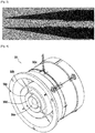
- the phase meter 30 comprises a cylindrical envelope 30a, inside which is arranged a plurality of electrodes 30b, 30c, 30d, 30e cylindrical and concentric with each other and with the cylindrical envelope 30a.
- the fluid flowing in the upstream pipe 10a flows inside the phase meter 30, along these electrodes.
- the electrodes allow an electrical capacitance to be measured, the value of which is representative of the gas content of the fluid flowing in the phase meter 30.
- the supply circuit 10 further comprises a recirculation channel 13.
- the recirculation channel 13 makes it possible to take a certain amount of fuel from the downstream pipe 10b.
- the recirculation channel 13 is connected in diversion to the downstream pipe 10b, between the first pump 12 and the second pump 14.
- the recirculation channel 13 is also connected to the upstream pipe 10a, upstream of the first pump 12 and downstream of the phase meter 30.
- a recirculation valve 18 is arranged on the recirculation channel 13.
- the opening of the recirculation valve 18 is controlled by a servovalve 16.
- the servovalve 16 controls the degree of opening of the recirculation valve 18, in d ' other words, the flow of fluid flowing in the recirculation channel 13, towards the upstream pipe 10a.
- a calculation unit 40 is connected to the phase meter 30 and to the servovalve 16.
- the control unit 40 can be of the FADEC type (for “Full Authority Digital Engine Control” in English).
- the gas content of the fluid flowing in the upstream pipe 10a, measured by the phase meter 30, is transmitted to the calculation unit 40.
- the calculation unit 40 sends a signal corresponding to the servovalve 16 which controls a degree of opening of the recirculation valve 18, according to the method described below.
- the first pump 12 is a centrifugal pump with a bladed impeller, with or without a bladed inductor upstream of said impeller. The operating principle of this centrifugal pump is described below.
- the energy is transmitted hydrodynamically.
- the fluid is accelerated by the wheel of the centrifugal pump.
- the work transmitted to the fluid, and therefore the pressure increase, is calculated from the speeds on the wheel, between the speed at the inlet of the blade and the speed at the outlet of the blade.
- the performance of the impeller therefore strongly depends on the speed triangle at the input of the pump. Indeed, the entry angle of a blading of a centrifugal pump is designed so as to guide the fluid in rotation for a given flow range. The presence of the gaseous phase at the inlet of the pump has a direct impact on the speed triangle at the inlet of the impeller, and therefore on the performance of the pump.
- the effective fuel passage section (illustrated by the gray portion on the figure 3 ) is reduced due to the occupation of the section by the gas phase (illustrated by the black portions on either side of the gray portion).
- the device according to this presentation consists in using the phase meter 30 upstream of the low pressure pump 12 in order to regulate the speed C u1 in blade entry and optimize pump performance, whatever the V / L ratio, and over the entire operating range in flow. It is also possible to block the passage of the fluid at the inlet of the low pressure pump 12.
- the phase meter 30 transmits the value V / L to the computer 40 which will control the servovalve 16, which in turn controls the recirculation valve 18 The latter then decreases the cross-section of the recirculation channel 13.
- the recirculation flow flowing in the recirculation channel is therefore reduced, as is the speed C u1 (with the ratio V / L).
- a speed C u1 is thus obtained at the inlet of the pump which is always consistent with the angle of attack of the inlet vane of the low pressure pump.
- the phase meter 30 detects a given value V / L, the operating point is then slightly shifted. To do this, the opening of the recirculation valve is reduced in order to reduce the fuel flow and get out of the critical point.
- the low pressure stage of the pump 12 may include a scroll.
- the behavior of the pump when V / L> 0 is in no way influenced by the presence of said volute.
Landscapes
- Engineering & Computer Science (AREA)
- Chemical & Material Sciences (AREA)
- Combustion & Propulsion (AREA)
- Mechanical Engineering (AREA)
- General Engineering & Computer Science (AREA)
- Structures Of Non-Positive Displacement Pumps (AREA)
- Control Of Non-Positive-Displacement Pumps (AREA)
- Flow Control (AREA)
- Control Of Positive-Displacement Pumps (AREA)
Applications Claiming Priority (1)
| Application Number | Priority Date | Filing Date | Title |
|---|---|---|---|
| FR1873060A FR3090042B1 (fr) | 2018-12-17 | 2018-12-17 | Dispositif amélioré de régulation de débit d’alimentation |
Publications (2)
| Publication Number | Publication Date |
|---|---|
| EP3670867A1 true EP3670867A1 (de) | 2020-06-24 |
| EP3670867B1 EP3670867B1 (de) | 2021-10-13 |
Family
ID=66542386
Family Applications (1)
| Application Number | Title | Priority Date | Filing Date |
|---|---|---|---|
| EP19215909.3A Active EP3670867B1 (de) | 2018-12-17 | 2019-12-13 | Verbesserte vorrichtung zur regulierung des versorgungsdurchsatzes |
Country Status (4)
| Country | Link |
|---|---|
| US (1) | US11136923B2 (de) |
| EP (1) | EP3670867B1 (de) |
| CN (1) | CN111322159B (de) |
| FR (1) | FR3090042B1 (de) |
Families Citing this family (2)
| Publication number | Priority date | Publication date | Assignee | Title |
|---|---|---|---|---|
| FR3115075B1 (fr) * | 2020-10-14 | 2022-10-21 | Safran Aircraft Engines | Circuit d’alimentation en carburant pour une chambre de combustion de turbomachine |
| US11828233B2 (en) * | 2021-11-26 | 2023-11-28 | Hamilton Sundstrand Corporation | Fuel pump systems |
Citations (3)
| Publication number | Priority date | Publication date | Assignee | Title |
|---|---|---|---|---|
| US4512722A (en) * | 1982-10-28 | 1985-04-23 | Societe Nationale d'Etude de Constudies de Mateurs d'Aviation | Device and process for monitoring cavitation in a positive displacement pump |
| US5490387A (en) * | 1994-05-25 | 1996-02-13 | Coltec Industries Inc | Flame-out resistant fuel pumping system |
| WO2018115653A1 (fr) * | 2016-12-22 | 2018-06-28 | Safran Aircraft Engines | Procede ameliore de regulation d'un circuit d'alimentation |
Family Cites Families (10)
| Publication number | Priority date | Publication date | Assignee | Title |
|---|---|---|---|---|
| FR2268956B1 (de) * | 1974-04-24 | 1977-06-24 | Messier Hispano Sa | |
| US5118258A (en) * | 1990-09-04 | 1992-06-02 | United Technologies Corporation | Dual pump fuel delivery system |
| US7007452B1 (en) * | 2003-06-13 | 2006-03-07 | Woodward Governor Company | Fuel system for a gas turbine engine |
| US7024796B2 (en) * | 2004-07-19 | 2006-04-11 | Earthrenew, Inc. | Process and apparatus for manufacture of fertilizer products from manure and sewage |
| US9222676B2 (en) * | 2010-12-30 | 2015-12-29 | Rolls-Royce Corporation | Supercritical or mixed phase fuel injector |
| CN102851080B (zh) * | 2011-06-30 | 2015-08-26 | 通用电气公司 | 整体气化联合循环发电系统和气化反应器以及方法 |
| FR2978828B1 (fr) * | 2011-08-02 | 2013-09-06 | Snecma | Capteur multi-electrode pour determiner la teneur en gaz dans un ecoulement diphasique |
| CA2923199C (en) * | 2015-03-12 | 2023-07-04 | Rolls-Royce Corporation | Return flow powered turbine |
| CN205001073U (zh) * | 2015-09-14 | 2016-01-27 | 中国能源建设集团广东省电力设计研究院有限公司 | 多燃料燃机的燃料处理及供应系统 |
| FR3042818B1 (fr) * | 2015-10-23 | 2021-12-03 | Snecma | Recirculation de fluide a travers une pompe centrifuge de turbomachine |
-
2018
- 2018-12-17 FR FR1873060A patent/FR3090042B1/fr not_active Expired - Fee Related
-
2019
- 2019-12-13 EP EP19215909.3A patent/EP3670867B1/de active Active
- 2019-12-16 US US16/715,129 patent/US11136923B2/en active Active
- 2019-12-17 CN CN201911298993.4A patent/CN111322159B/zh active Active
Patent Citations (3)
| Publication number | Priority date | Publication date | Assignee | Title |
|---|---|---|---|---|
| US4512722A (en) * | 1982-10-28 | 1985-04-23 | Societe Nationale d'Etude de Constudies de Mateurs d'Aviation | Device and process for monitoring cavitation in a positive displacement pump |
| US5490387A (en) * | 1994-05-25 | 1996-02-13 | Coltec Industries Inc | Flame-out resistant fuel pumping system |
| WO2018115653A1 (fr) * | 2016-12-22 | 2018-06-28 | Safran Aircraft Engines | Procede ameliore de regulation d'un circuit d'alimentation |
Also Published As
| Publication number | Publication date |
|---|---|
| US11136923B2 (en) | 2021-10-05 |
| CN111322159B (zh) | 2024-04-02 |
| FR3090042A1 (fr) | 2020-06-19 |
| FR3090042B1 (fr) | 2021-04-09 |
| CN111322159A (zh) | 2020-06-23 |
| EP3670867B1 (de) | 2021-10-13 |
| US20200191064A1 (en) | 2020-06-18 |
Similar Documents
| Publication | Publication Date | Title |
|---|---|---|
| EP2564045B1 (de) | Kraftstoffsystem einer turbomaschine | |
| CA2597938C (fr) | Alimentation en carburant d'un moteur d'aeronef | |
| EP3365545B1 (de) | Rückführung von flüssigkeit durch eine turbomaschinenkreiselpumpe | |
| CA2721423C (fr) | Injection d'air dans la veine d'un compresseur de turbomachine | |
| EP0307264B1 (de) | Kraftstoffverteilungssystem mit verbesserter Kraftstoffkühlung | |
| FR2953563A1 (fr) | Installation d'alimentation en carburant d'un turboreacteur d'avion | |
| EP3670867B1 (de) | Verbesserte vorrichtung zur regulierung des versorgungsdurchsatzes | |
| FR3022000A1 (fr) | Systeme d'alimentation de turbomachine en fluide avec un ensemble de pompage basse pression comprenant deux pompes en parallele | |
| EP3559430B1 (de) | Verbessertes verfahren zur regelung einer speiseschaltung | |
| EP3959427B1 (de) | Verfahren zur regelung einer turbomaschine mit einer temporären leistungserhöhungsvorrichtung | |
| EP3994358B1 (de) | Überspannungsschutzregelung für einen ladekompressor, der mit einem hilfsantrieb ausgestattet ist | |
| EP3569866A1 (de) | Kompressor und verfahren zur kontrolle des durchsatzes | |
| EP3475547B1 (de) | Schaltung und verfahren zum dosieren von kraftstoff mit kompensation von schwankungen der kraftstoffdichte | |
| FR2704905A1 (fr) | Turbomachine comportant un régulateur secondaire du débit de son alimentation en carburant. | |
| EP3449134B1 (de) | Strahlpumpe für eine turbomaschine mit beschaufelung zur rotation einer aktiven flüssigkeit | |
| FR3108657A1 (fr) | Rotor de turbine comprenant un dispositif de régulation du débit de fluide de refroidissement et turbomachine comprenant un tel rotor | |
| FR3153856A1 (fr) | Systeme d’alimentation en carburant de turbomachine | |
| WO2025074053A1 (fr) | Systeme d'alimentation en carburant de turbomachine | |
| WO2025062085A1 (fr) | Dispositif de controle des transitoires de poussee d'une turbomachine | |
| FR2986272A1 (fr) | Dispositif fluidique avec vanne de retour de carburant pour moteurs d'aeronefs, et procede d'obtention d'un tel dispositif | |
| WO2025062106A1 (fr) | Systeme d'alimentation en carburant d'une turbomachine | |
| FR3087258A1 (fr) | Dispositif d'alimentation en air comprime d'un aeronef et son procede d'utilisation | |
| FR3081029A1 (fr) | Dispositif de commande de variation du calage d'une aube de redresseur | |
| FR3074849A1 (fr) | Turbomachine d'aeronef a au moins deux corps comprenant des moyens de derivation de gaz comprimes |
Legal Events
| Date | Code | Title | Description |
|---|---|---|---|
| PUAI | Public reference made under article 153(3) epc to a published international application that has entered the european phase |
Free format text: ORIGINAL CODE: 0009012 |
|
| STAA | Information on the status of an ep patent application or granted ep patent |
Free format text: STATUS: REQUEST FOR EXAMINATION WAS MADE |
|
| 17P | Request for examination filed |
Effective date: 20191213 |
|
| AK | Designated contracting states |
Kind code of ref document: A1 Designated state(s): AL AT BE BG CH CY CZ DE DK EE ES FI FR GB GR HR HU IE IS IT LI LT LU LV MC MK MT NL NO PL PT RO RS SE SI SK SM TR |
|
| GRAP | Despatch of communication of intention to grant a patent |
Free format text: ORIGINAL CODE: EPIDOSNIGR1 |
|
| STAA | Information on the status of an ep patent application or granted ep patent |
Free format text: STATUS: GRANT OF PATENT IS INTENDED |
|
| INTG | Intention to grant announced |
Effective date: 20210702 |
|
| GRAS | Grant fee paid |
Free format text: ORIGINAL CODE: EPIDOSNIGR3 |
|
| GRAA | (expected) grant |
Free format text: ORIGINAL CODE: 0009210 |
|
| STAA | Information on the status of an ep patent application or granted ep patent |
Free format text: STATUS: THE PATENT HAS BEEN GRANTED |
|
| AK | Designated contracting states |
Kind code of ref document: B1 Designated state(s): AL AT BE BG CH CY CZ DE DK EE ES FI FR GB GR HR HU IE IS IT LI LT LU LV MC MK MT NL NO PL PT RO RS SE SI SK SM TR |
|
| REG | Reference to a national code |
Ref country code: GB Ref legal event code: FG4D Free format text: NOT ENGLISH |
|
| REG | Reference to a national code |
Ref country code: CH Ref legal event code: EP |
|
| REG | Reference to a national code |
Ref country code: DE Ref legal event code: R096 Ref document number: 602019008333 Country of ref document: DE |
|
| REG | Reference to a national code |
Ref country code: IE Ref legal event code: FG4D Free format text: LANGUAGE OF EP DOCUMENT: FRENCH |
|
| REG | Reference to a national code |
Ref country code: AT Ref legal event code: REF Ref document number: 1438359 Country of ref document: AT Kind code of ref document: T Effective date: 20211115 |
|
| REG | Reference to a national code |
Ref country code: SE Ref legal event code: TRGR |
|
| REG | Reference to a national code |
Ref country code: LT Ref legal event code: MG9D |
|
| REG | Reference to a national code |
Ref country code: NL Ref legal event code: MP Effective date: 20211013 |
|
| REG | Reference to a national code |
Ref country code: AT Ref legal event code: MK05 Ref document number: 1438359 Country of ref document: AT Kind code of ref document: T Effective date: 20211013 |
|
| PG25 | Lapsed in a contracting state [announced via postgrant information from national office to epo] |
Ref country code: RS Free format text: LAPSE BECAUSE OF FAILURE TO SUBMIT A TRANSLATION OF THE DESCRIPTION OR TO PAY THE FEE WITHIN THE PRESCRIBED TIME-LIMIT Effective date: 20211013 Ref country code: LT Free format text: LAPSE BECAUSE OF FAILURE TO SUBMIT A TRANSLATION OF THE DESCRIPTION OR TO PAY THE FEE WITHIN THE PRESCRIBED TIME-LIMIT Effective date: 20211013 Ref country code: FI Free format text: LAPSE BECAUSE OF FAILURE TO SUBMIT A TRANSLATION OF THE DESCRIPTION OR TO PAY THE FEE WITHIN THE PRESCRIBED TIME-LIMIT Effective date: 20211013 Ref country code: BG Free format text: LAPSE BECAUSE OF FAILURE TO SUBMIT A TRANSLATION OF THE DESCRIPTION OR TO PAY THE FEE WITHIN THE PRESCRIBED TIME-LIMIT Effective date: 20220113 Ref country code: AT Free format text: LAPSE BECAUSE OF FAILURE TO SUBMIT A TRANSLATION OF THE DESCRIPTION OR TO PAY THE FEE WITHIN THE PRESCRIBED TIME-LIMIT Effective date: 20211013 |
|
| PG25 | Lapsed in a contracting state [announced via postgrant information from national office to epo] |
Ref country code: IS Free format text: LAPSE BECAUSE OF FAILURE TO SUBMIT A TRANSLATION OF THE DESCRIPTION OR TO PAY THE FEE WITHIN THE PRESCRIBED TIME-LIMIT Effective date: 20220213 Ref country code: PT Free format text: LAPSE BECAUSE OF FAILURE TO SUBMIT A TRANSLATION OF THE DESCRIPTION OR TO PAY THE FEE WITHIN THE PRESCRIBED TIME-LIMIT Effective date: 20220214 Ref country code: PL Free format text: LAPSE BECAUSE OF FAILURE TO SUBMIT A TRANSLATION OF THE DESCRIPTION OR TO PAY THE FEE WITHIN THE PRESCRIBED TIME-LIMIT Effective date: 20211013 Ref country code: NO Free format text: LAPSE BECAUSE OF FAILURE TO SUBMIT A TRANSLATION OF THE DESCRIPTION OR TO PAY THE FEE WITHIN THE PRESCRIBED TIME-LIMIT Effective date: 20220113 Ref country code: NL Free format text: LAPSE BECAUSE OF FAILURE TO SUBMIT A TRANSLATION OF THE DESCRIPTION OR TO PAY THE FEE WITHIN THE PRESCRIBED TIME-LIMIT Effective date: 20211013 Ref country code: LV Free format text: LAPSE BECAUSE OF FAILURE TO SUBMIT A TRANSLATION OF THE DESCRIPTION OR TO PAY THE FEE WITHIN THE PRESCRIBED TIME-LIMIT Effective date: 20211013 Ref country code: HR Free format text: LAPSE BECAUSE OF FAILURE TO SUBMIT A TRANSLATION OF THE DESCRIPTION OR TO PAY THE FEE WITHIN THE PRESCRIBED TIME-LIMIT Effective date: 20211013 Ref country code: GR Free format text: LAPSE BECAUSE OF FAILURE TO SUBMIT A TRANSLATION OF THE DESCRIPTION OR TO PAY THE FEE WITHIN THE PRESCRIBED TIME-LIMIT Effective date: 20220114 Ref country code: ES Free format text: LAPSE BECAUSE OF FAILURE TO SUBMIT A TRANSLATION OF THE DESCRIPTION OR TO PAY THE FEE WITHIN THE PRESCRIBED TIME-LIMIT Effective date: 20211013 |
|
| REG | Reference to a national code |
Ref country code: DE Ref legal event code: R097 Ref document number: 602019008333 Country of ref document: DE |
|
| PG25 | Lapsed in a contracting state [announced via postgrant information from national office to epo] |
Ref country code: SM Free format text: LAPSE BECAUSE OF FAILURE TO SUBMIT A TRANSLATION OF THE DESCRIPTION OR TO PAY THE FEE WITHIN THE PRESCRIBED TIME-LIMIT Effective date: 20211013 Ref country code: SK Free format text: LAPSE BECAUSE OF FAILURE TO SUBMIT A TRANSLATION OF THE DESCRIPTION OR TO PAY THE FEE WITHIN THE PRESCRIBED TIME-LIMIT Effective date: 20211013 Ref country code: RO Free format text: LAPSE BECAUSE OF FAILURE TO SUBMIT A TRANSLATION OF THE DESCRIPTION OR TO PAY THE FEE WITHIN THE PRESCRIBED TIME-LIMIT Effective date: 20211013 Ref country code: MC Free format text: LAPSE BECAUSE OF FAILURE TO SUBMIT A TRANSLATION OF THE DESCRIPTION OR TO PAY THE FEE WITHIN THE PRESCRIBED TIME-LIMIT Effective date: 20211013 Ref country code: EE Free format text: LAPSE BECAUSE OF FAILURE TO SUBMIT A TRANSLATION OF THE DESCRIPTION OR TO PAY THE FEE WITHIN THE PRESCRIBED TIME-LIMIT Effective date: 20211013 Ref country code: DK Free format text: LAPSE BECAUSE OF FAILURE TO SUBMIT A TRANSLATION OF THE DESCRIPTION OR TO PAY THE FEE WITHIN THE PRESCRIBED TIME-LIMIT Effective date: 20211013 Ref country code: CZ Free format text: LAPSE BECAUSE OF FAILURE TO SUBMIT A TRANSLATION OF THE DESCRIPTION OR TO PAY THE FEE WITHIN THE PRESCRIBED TIME-LIMIT Effective date: 20211013 |
|
| PLBE | No opposition filed within time limit |
Free format text: ORIGINAL CODE: 0009261 |
|
| STAA | Information on the status of an ep patent application or granted ep patent |
Free format text: STATUS: NO OPPOSITION FILED WITHIN TIME LIMIT |
|
| 26N | No opposition filed |
Effective date: 20220714 |
|
| REG | Reference to a national code |
Ref country code: BE Ref legal event code: MM Effective date: 20211231 |
|
| PG25 | Lapsed in a contracting state [announced via postgrant information from national office to epo] |
Ref country code: LU Free format text: LAPSE BECAUSE OF NON-PAYMENT OF DUE FEES Effective date: 20211213 Ref country code: IE Free format text: LAPSE BECAUSE OF NON-PAYMENT OF DUE FEES Effective date: 20211213 Ref country code: AL Free format text: LAPSE BECAUSE OF FAILURE TO SUBMIT A TRANSLATION OF THE DESCRIPTION OR TO PAY THE FEE WITHIN THE PRESCRIBED TIME-LIMIT Effective date: 20211013 |
|
| PG25 | Lapsed in a contracting state [announced via postgrant information from national office to epo] |
Ref country code: SI Free format text: LAPSE BECAUSE OF FAILURE TO SUBMIT A TRANSLATION OF THE DESCRIPTION OR TO PAY THE FEE WITHIN THE PRESCRIBED TIME-LIMIT Effective date: 20211013 Ref country code: BE Free format text: LAPSE BECAUSE OF NON-PAYMENT OF DUE FEES Effective date: 20211231 |
|
| PG25 | Lapsed in a contracting state [announced via postgrant information from national office to epo] |
Ref country code: CY Free format text: LAPSE BECAUSE OF FAILURE TO SUBMIT A TRANSLATION OF THE DESCRIPTION OR TO PAY THE FEE WITHIN THE PRESCRIBED TIME-LIMIT Effective date: 20211013 |
|
| PG25 | Lapsed in a contracting state [announced via postgrant information from national office to epo] |
Ref country code: HU Free format text: LAPSE BECAUSE OF FAILURE TO SUBMIT A TRANSLATION OF THE DESCRIPTION OR TO PAY THE FEE WITHIN THE PRESCRIBED TIME-LIMIT; INVALID AB INITIO Effective date: 20191213 |
|
| REG | Reference to a national code |
Ref country code: CH Ref legal event code: PL |
|
| PG25 | Lapsed in a contracting state [announced via postgrant information from national office to epo] |
Ref country code: LI Free format text: LAPSE BECAUSE OF NON-PAYMENT OF DUE FEES Effective date: 20221231 Ref country code: CH Free format text: LAPSE BECAUSE OF NON-PAYMENT OF DUE FEES Effective date: 20221231 |
|
| PG25 | Lapsed in a contracting state [announced via postgrant information from national office to epo] |
Ref country code: MK Free format text: LAPSE BECAUSE OF FAILURE TO SUBMIT A TRANSLATION OF THE DESCRIPTION OR TO PAY THE FEE WITHIN THE PRESCRIBED TIME-LIMIT Effective date: 20211013 |
|
| PG25 | Lapsed in a contracting state [announced via postgrant information from national office to epo] |
Ref country code: MT Free format text: LAPSE BECAUSE OF FAILURE TO SUBMIT A TRANSLATION OF THE DESCRIPTION OR TO PAY THE FEE WITHIN THE PRESCRIBED TIME-LIMIT Effective date: 20211013 |
|
| PG25 | Lapsed in a contracting state [announced via postgrant information from national office to epo] |
Ref country code: TR Free format text: LAPSE BECAUSE OF FAILURE TO SUBMIT A TRANSLATION OF THE DESCRIPTION OR TO PAY THE FEE WITHIN THE PRESCRIBED TIME-LIMIT Effective date: 20211013 |
|
| PGFP | Annual fee paid to national office [announced via postgrant information from national office to epo] |
Ref country code: GB Payment date: 20251229 Year of fee payment: 7 |
|
| PGFP | Annual fee paid to national office [announced via postgrant information from national office to epo] |
Ref country code: FR Payment date: 20251222 Year of fee payment: 7 |
|
| PGFP | Annual fee paid to national office [announced via postgrant information from national office to epo] |
Ref country code: SE Payment date: 20251217 Year of fee payment: 7 |
|
| PGFP | Annual fee paid to national office [announced via postgrant information from national office to epo] |
Ref country code: DE Payment date: 20251222 Year of fee payment: 7 |
|
| PGFP | Annual fee paid to national office [announced via postgrant information from national office to epo] |
Ref country code: IT Payment date: 20251231 Year of fee payment: 7 |