EP3670899A1 - Method for assembling a wind turbine and wind turbine assembled according to said method - Google Patents
Method for assembling a wind turbine and wind turbine assembled according to said method Download PDFInfo
- Publication number
- EP3670899A1 EP3670899A1 EP18382969.6A EP18382969A EP3670899A1 EP 3670899 A1 EP3670899 A1 EP 3670899A1 EP 18382969 A EP18382969 A EP 18382969A EP 3670899 A1 EP3670899 A1 EP 3670899A1
- Authority
- EP
- European Patent Office
- Prior art keywords
- annular section
- annular
- connections
- wind turbine
- sections
- Prior art date
- Legal status (The legal status is an assumption and is not a legal conclusion. Google has not performed a legal analysis and makes no representation as to the accuracy of the status listed.)
- Granted
Links
Images


Classifications
-
- F—MECHANICAL ENGINEERING; LIGHTING; HEATING; WEAPONS; BLASTING
- F03—MACHINES OR ENGINES FOR LIQUIDS; WIND, SPRING, OR WEIGHT MOTORS; PRODUCING MECHANICAL POWER OR A REACTIVE PROPULSIVE THRUST, NOT OTHERWISE PROVIDED FOR
- F03D—WIND MOTORS
- F03D13/00—Assembly, mounting or commissioning of wind motors; Arrangements specially adapted for transporting wind motor components
- F03D13/20—Arrangements for mounting or supporting wind motors; Masts or towers for wind motors
-
- F—MECHANICAL ENGINEERING; LIGHTING; HEATING; WEAPONS; BLASTING
- F03—MACHINES OR ENGINES FOR LIQUIDS; WIND, SPRING, OR WEIGHT MOTORS; PRODUCING MECHANICAL POWER OR A REACTIVE PROPULSIVE THRUST, NOT OTHERWISE PROVIDED FOR
- F03D—WIND MOTORS
- F03D13/00—Assembly, mounting or commissioning of wind motors; Arrangements specially adapted for transporting wind motor components
- F03D13/10—Assembly of wind motors; Arrangements for erecting wind motors
-
- F—MECHANICAL ENGINEERING; LIGHTING; HEATING; WEAPONS; BLASTING
- F03—MACHINES OR ENGINES FOR LIQUIDS; WIND, SPRING, OR WEIGHT MOTORS; PRODUCING MECHANICAL POWER OR A REACTIVE PROPULSIVE THRUST, NOT OTHERWISE PROVIDED FOR
- F03D—WIND MOTORS
- F03D13/00—Assembly, mounting or commissioning of wind motors; Arrangements specially adapted for transporting wind motor components
- F03D13/10—Assembly of wind motors; Arrangements for erecting wind motors
- F03D13/112—Assembly of wind motors; Arrangements for erecting wind motors of towers; of masts
-
- F—MECHANICAL ENGINEERING; LIGHTING; HEATING; WEAPONS; BLASTING
- F03—MACHINES OR ENGINES FOR LIQUIDS; WIND, SPRING, OR WEIGHT MOTORS; PRODUCING MECHANICAL POWER OR A REACTIVE PROPULSIVE THRUST, NOT OTHERWISE PROVIDED FOR
- F03D—WIND MOTORS
- F03D13/00—Assembly, mounting or commissioning of wind motors; Arrangements specially adapted for transporting wind motor components
- F03D13/20—Arrangements for mounting or supporting wind motors; Masts or towers for wind motors
- F03D13/201—Towers
- F03D13/205—Connection means, e.g. joints between segments
-
- E—FIXED CONSTRUCTIONS
- E04—BUILDING
- E04H—BUILDINGS OR LIKE STRUCTURES FOR PARTICULAR PURPOSES; SWIMMING OR SPLASH BATHS OR POOLS; MASTS; FENCING; TENTS OR CANOPIES, IN GENERAL
- E04H12/00—Towers; Masts or poles; Chimney stacks; Water-towers; Methods of erecting such structures
- E04H12/02—Structures made of specified materials
- E04H12/12—Structures made of specified materials of concrete or other stone-like material, with or without internal or external reinforcements, e.g. with metal coverings, with permanent form elements
-
- E—FIXED CONSTRUCTIONS
- E04—BUILDING
- E04H—BUILDINGS OR LIKE STRUCTURES FOR PARTICULAR PURPOSES; SWIMMING OR SPLASH BATHS OR POOLS; MASTS; FENCING; TENTS OR CANOPIES, IN GENERAL
- E04H12/00—Towers; Masts or poles; Chimney stacks; Water-towers; Methods of erecting such structures
- E04H12/34—Arrangements for erecting or lowering towers, masts, poles, chimney stacks, or the like
- E04H12/342—Arrangements for stacking tower sections on top of each other
-
- E—FIXED CONSTRUCTIONS
- E04—BUILDING
- E04H—BUILDINGS OR LIKE STRUCTURES FOR PARTICULAR PURPOSES; SWIMMING OR SPLASH BATHS OR POOLS; MASTS; FENCING; TENTS OR CANOPIES, IN GENERAL
- E04H9/00—Buildings, groups of buildings or shelters adapted to withstand or provide protection against abnormal external influences, e.g. war-like action, earthquake or extreme climate
-
- F—MECHANICAL ENGINEERING; LIGHTING; HEATING; WEAPONS; BLASTING
- F05—INDEXING SCHEMES RELATING TO ENGINES OR PUMPS IN VARIOUS SUBCLASSES OF CLASSES F01-F04
- F05B—INDEXING SCHEME RELATING TO WIND, SPRING, WEIGHT, INERTIA OR LIKE MOTORS, TO MACHINES OR ENGINES FOR LIQUIDS COVERED BY SUBCLASSES F03B, F03D AND F03G
- F05B2230/00—Manufacture
- F05B2230/60—Assembly methods
- F05B2230/61—Assembly methods using auxiliary equipment for lifting or holding
-
- F—MECHANICAL ENGINEERING; LIGHTING; HEATING; WEAPONS; BLASTING
- F05—INDEXING SCHEMES RELATING TO ENGINES OR PUMPS IN VARIOUS SUBCLASSES OF CLASSES F01-F04
- F05B—INDEXING SCHEME RELATING TO WIND, SPRING, WEIGHT, INERTIA OR LIKE MOTORS, TO MACHINES OR ENGINES FOR LIQUIDS COVERED BY SUBCLASSES F03B, F03D AND F03G
- F05B2240/00—Components
- F05B2240/40—Use of a multiplicity of similar components
-
- F—MECHANICAL ENGINEERING; LIGHTING; HEATING; WEAPONS; BLASTING
- F05—INDEXING SCHEMES RELATING TO ENGINES OR PUMPS IN VARIOUS SUBCLASSES OF CLASSES F01-F04
- F05B—INDEXING SCHEME RELATING TO WIND, SPRING, WEIGHT, INERTIA OR LIKE MOTORS, TO MACHINES OR ENGINES FOR LIQUIDS COVERED BY SUBCLASSES F03B, F03D AND F03G
- F05B2260/00—Function
- F05B2260/30—Retaining components in desired mutual position
- F05B2260/301—Retaining bolts or nuts
-
- Y—GENERAL TAGGING OF NEW TECHNOLOGICAL DEVELOPMENTS; GENERAL TAGGING OF CROSS-SECTIONAL TECHNOLOGIES SPANNING OVER SEVERAL SECTIONS OF THE IPC; TECHNICAL SUBJECTS COVERED BY FORMER USPC CROSS-REFERENCE ART COLLECTIONS [XRACs] AND DIGESTS
- Y02—TECHNOLOGIES OR APPLICATIONS FOR MITIGATION OR ADAPTATION AGAINST CLIMATE CHANGE
- Y02E—REDUCTION OF GREENHOUSE GAS [GHG] EMISSIONS, RELATED TO ENERGY GENERATION, TRANSMISSION OR DISTRIBUTION
- Y02E10/00—Energy generation through renewable energy sources
- Y02E10/70—Wind energy
- Y02E10/72—Wind turbines with rotation axis in wind direction
-
- Y—GENERAL TAGGING OF NEW TECHNOLOGICAL DEVELOPMENTS; GENERAL TAGGING OF CROSS-SECTIONAL TECHNOLOGIES SPANNING OVER SEVERAL SECTIONS OF THE IPC; TECHNICAL SUBJECTS COVERED BY FORMER USPC CROSS-REFERENCE ART COLLECTIONS [XRACs] AND DIGESTS
- Y02—TECHNOLOGIES OR APPLICATIONS FOR MITIGATION OR ADAPTATION AGAINST CLIMATE CHANGE
- Y02E—REDUCTION OF GREENHOUSE GAS [GHG] EMISSIONS, RELATED TO ENERGY GENERATION, TRANSMISSION OR DISTRIBUTION
- Y02E10/00—Energy generation through renewable energy sources
- Y02E10/70—Wind energy
- Y02E10/728—Onshore wind turbines
-
- Y—GENERAL TAGGING OF NEW TECHNOLOGICAL DEVELOPMENTS; GENERAL TAGGING OF CROSS-SECTIONAL TECHNOLOGIES SPANNING OVER SEVERAL SECTIONS OF THE IPC; TECHNICAL SUBJECTS COVERED BY FORMER USPC CROSS-REFERENCE ART COLLECTIONS [XRACs] AND DIGESTS
- Y02—TECHNOLOGIES OR APPLICATIONS FOR MITIGATION OR ADAPTATION AGAINST CLIMATE CHANGE
- Y02P—CLIMATE CHANGE MITIGATION TECHNOLOGIES IN THE PRODUCTION OR PROCESSING OF GOODS
- Y02P70/00—Climate change mitigation technologies in the production process for final industrial or consumer products
- Y02P70/50—Manufacturing or production processes characterised by the final manufactured product
Definitions
- the object of the invention is a method for assembling a wind turbine in locations where earthquakes may occur which, using suitable means, achieves a balance between the speed of execution of the assembly of the wind turbine and the guarantee that the tower will resist loads associated with possible earthquakes during the assembly.
- Another object of the present invention is a wind turbine assembled according to the above method.
- the tower Due to the height of the wind turbines, the tower has to be divided into several annular sections which are stacked during the wind turbine assembly stage thus forming the full height of the tower. Dividing the tower into sections has the advantage that each section has a size such that its transport by road or rail is easier.
- Document EP2541047 discloses a method for assembling a wind turbine comprising: a tower comprising a plurality of concrete annular sections; a nacelle and a rotor; the method comprising the nacelle on one upper section of the concrete annular sections, and then assembling the rotor to the nacelle, wherein main connections for connecting the concrete annular sections to each other using main connecting means for resisting the loads provoked by the rotor are performed after stacking the nacelle onto the upper annular section and before assembling the rotor to the nacelle.
- this method does not take into account the possibility of occurrence of earthquakes during the assembly of the wind turbine, so it would not be feasible for seismic locations.
- the method of the present invention solves the problem described above, by providing a method and a system capable of making the wind turbine subassembly stable during the assembly of the same in the event of an earthquake.
- This invention describes the characteristics of connections between sections of the tower which are carried out during the assembly of the wind turbine that allow not only to execute them very quickly but also to minimize the risk of collapse of the wind turbine in the event of an earthquake.
- the invention provides a method for assembling a wind turbine comprising a stage wherein auxiliary connections are performed between a first and a second annular sections before stacking a third section, so that the possibility of an earthquake damaging the wind turbine during its assembly is minimized. This is achieved by reducing the time that the sections remain without any connection capable of withstanding said potential seismic loads.
- the method object of the invention is implemented in a wind turbine comprising a tower, a nacelle and a rotor.
- the tower is of the type comprising stackable annular sections, wherein at least two of these annular sections, e.g a first and a second annular sections, are made preferably of concrete.
- the invention relates, according to a first aspect thereof, to an assembly method for a wind turbine comprising a tower (1), a nacelle (2) and a rotor.
- the tower (1) is of the type comprising stackable annular sections (3, 4, 5, 6), wherein at least two of the annular sections (3, 4, 5, 6), e.g. a first (3) and a second (4) annular sections, are made of concrete.
- the method of the invention relates to stacking, upon the first annular section (3), the second annular section (4) and, once the second annular section is stacked, connecting the first annular section (3) to the second annular section (4) by means of performing auxiliary connections capable of withstanding seismic loads induced by an earthquake, for allowing the tower (1) to withstand loads induced by an earthquake that may occur during assembling.
- the steps of stacking and performing auxiliary connections are performed for any further annular concrete section (5, 6), so that the auxiliary connections still allow the connected sections (4, 5, 6) to withstand loads induced by an earthquake that may occur during the assembly.
- This step is repeated with the rest of the concrete annular sections (5, 6) until all concrete annular sections (3, 4, 5, 6) are stacked upon each other.
- the main connection connecting the nacelle (2) to the top annular section is performed before performing any of the main connections connecting the annular sections (3, 4, 5, 6) to each other, wherein the main connections connecting annular sections (3, 4, 5, 6) located upwardly are performed before those for annular sections (3, 4, 5, 6) located near the bottom due to the upper sections have a greater possibility of overturning in case of earthquakes.
- the main connections may be performed beginning with a bottom part of the tower (1), i.e., first the main connection connecting the first annular section (3) to the second annular section (4), and then the main connection connecting the second annular sections (4) to the third annular section (5) and so on.
- annular section (4, 5, 6) In general, for each pair of adjacent annular sections (3, 4, 5, 6) made of concrete, one of the adjacent annular sections (3, 4, 5, 6), referred to as upper annular section (4, 5, 6) is stacked upon the other adjacent annular section (3, 4, 5, 6), referred to as lower annular section (3, 4, 5), wherein the upper annular section (4, 5, 6) has bars (8) as explained above for the second annular section (4), whereas the lower annular section (3, 4, 5) has housings (9) as explained above for the first annular section (3).
- Figure 3 also shows the connection between a lower and an upper annular sections, specifically first (3) and second (4) annular sections.
- the resin (11) is inserted (preferably poured) in at least one of the housings (9) of the lower annular section (3, 4, 5).
- resin (11) may be inserted so that some or all of the housings (9) are partially or totally filled with resin (11).
- the housings (9) which are filled with resin (11) are preferably filled up to 30%, more preferably up to 40 %, of the volume of the housings (9).
- the resin (11) is preferably inserted in non-contiguous housings (9), see figure 3 .
- Stacking an annular section (4, 5, 6) upon a previously mounted annular section (3, 4, 5) may take a stacking time of approximatively 3 hours.
- performing any auxiliary connection takes a time which is shorter than the stacking time, so that the assembling of the wind turbine is not delayed by performing the auxiliary connections.
- the time taken for performing an auxiliary connection may be preselected by, for instance, selecting an appropriate kind of resin (11).
- the partial application of resin (11) in the housings (9) of each annular concrete section (3, 4, 5, 6), as explained above, is preferably done in a time shorter than or equal to the first pre-set time of application of the resin (11) in order to reduce the possibility of the tower (1) collapsing in the eventual occurrence of an earthquake and also in order to reduce the spectrum of loads that the auxiliary connection has to withstand; if the application of resin (11) takes more time, the exposure time increases, and the greater the exposure time the higher the probability of having an earthquake of a greater magnitude.
- the auxiliary connections enable the tower (1) to withstand the loads that may suffer the structure in such an event. In this sense, the sooner the auxiliary connections are finished, the lower the exposure time of the annular sections (3, 4, 5, 6) to a potential earthquake without safe connections.
- Main connections show grout (10) inserted in the housings (9) and in the gap (18) that exists between the two adjacent annular sections.
- Main connections show grout (10) inserted in the housings (9) and in the gap (18) that exists between the two adjacent annular sections.
- the rotor is placed, and the wind turbine is capable of withstanding all operational loads induced by said rotor once in operation (due to the wind acting on the surface of the blades and the rotor's own weight).
Landscapes
- Engineering & Computer Science (AREA)
- Chemical & Material Sciences (AREA)
- Life Sciences & Earth Sciences (AREA)
- Mechanical Engineering (AREA)
- Sustainable Energy (AREA)
- Combustion & Propulsion (AREA)
- Sustainable Development (AREA)
- General Engineering & Computer Science (AREA)
- Architecture (AREA)
- Civil Engineering (AREA)
- Structural Engineering (AREA)
- Materials Engineering (AREA)
- Wood Science & Technology (AREA)
- Wind Motors (AREA)
Abstract
Description
- The object of the invention is a method for assembling a wind turbine in locations where earthquakes may occur which, using suitable means, achieves a balance between the speed of execution of the assembly of the wind turbine and the guarantee that the tower will resist loads associated with possible earthquakes during the assembly.
- Another object of the present invention is a wind turbine assembled according to the above method.
- The wind turbines comprise a tower, a nacelle which houses the electrical generator and a rotor formed in turn by at least two blades. The tower of the wind turbine supports the nacelle and the rotor. Large wind turbines have steel, lattice, or reinforced concrete towers or even mixed-type towers, the latter comprising sections of different materials, for example, a lower section of concrete and an upper section of steel or lattice.
- Due to the height of the wind turbines, the tower has to be divided into several annular sections which are stacked during the wind turbine assembly stage thus forming the full height of the tower. Dividing the tower into sections has the advantage that each section has a size such that its transport by road or rail is easier.
- One of the most commonly used materials for large towers is concrete, since it involves competitive costs and performance compared to those for the production of steel towers of similar characteristics. However, the weight of each concrete tower section can easily exceed one hundred tons, this fact being infrequent for metal tower sections, so stacking the concrete sections requires heavy-tonnage lifting and positioning means. The cost of using such lifting and positioning means, which may be for example a crane, is directly related to the tonnage and height that it is capable of handling and the time of use thereof. This high-tonnage crane is also used for lifting and positioning the nacelle, as the weight of the nacelle may also exceed 100 tons.
- The design of wind turbine components and the design of the connections between them once placed, should take into account the loads they will have to bear throughout their useful life to ensure the proper functioning thereof. In particular, the connections between different concrete sections of the tower are adapted to withstand the loads they will have to bear throughout their useful life.
- In addition to the expected loads that the wind turbine must bear, such as gravitational loads, assembly loads, inertial loads, aerodynamic loads, operational loads, etc., other loads must also be taken into account, depending on the location where the wind turbine is to be installed, such as earthquakes.
- As it is known, an earthquake is a phenomenon of sudden and transient shaking of the surface of the Earth produced by the release of accumulated energy in the form of seismic waves, and of course, wind turbines do not escape this reality. Therefore, the construction period of the wind turbine is a very vulnerable situation, since a seismic event could occur during the assembly of the wind turbines, when the wind turbine components have not been fully fixed.
- Document
EP2541047 (Acciona Windpower) discloses a method for assembling a wind turbine comprising: a tower comprising a plurality of concrete annular sections; a nacelle and a rotor; the method comprising the nacelle on one upper section of the concrete annular sections, and then assembling the rotor to the nacelle, wherein main connections for connecting the concrete annular sections to each other using main connecting means for resisting the loads provoked by the rotor are performed after stacking the nacelle onto the upper annular section and before assembling the rotor to the nacelle. However, this method does not take into account the possibility of occurrence of earthquakes during the assembly of the wind turbine, so it would not be feasible for seismic locations. - Therefore, the method of the present invention solves the problem described above, by providing a method and a system capable of making the wind turbine subassembly stable during the assembly of the same in the event of an earthquake.
- This invention describes the characteristics of connections between sections of the tower which are carried out during the assembly of the wind turbine that allow not only to execute them very quickly but also to minimize the risk of collapse of the wind turbine in the event of an earthquake.
- More particularly, the invention provides a method for assembling a wind turbine comprising a stage wherein auxiliary connections are performed between a first and a second annular sections before stacking a third section, so that the possibility of an earthquake damaging the wind turbine during its assembly is minimized. This is achieved by reducing the time that the sections remain without any connection capable of withstanding said potential seismic loads.
- The method object of the invention is implemented in a wind turbine comprising a tower, a nacelle and a rotor. The tower is of the type comprising stackable annular sections, wherein at least two of these annular sections, e.g a first and a second annular sections, are made preferably of concrete.
- As a general concept, according to the method of the invention, all annular sections are consecutively stacked upon each other, wherein one of the annular sections, referred to as "top annular section", is stacked atop of all the other annular sections, and finally the nacelle is stacked upon the top annular section. The auxiliary connections are performed not only for connecting the second annular section to the first annular section, but also auxiliary connections are performed, for connecting the third annular section to the second annular section, after the third annular section is stacked, but before a fourth annular section, or the nacelle, are stacked, an so on.
- As a consequence, during the period of time that it takes the wind turbine to be completely assembled, the wind turbine is protected against eventual seismic loads, since auxiliary connections are provided as the annular sections are being stacked.
- For withstanding all operation loads induced by the wind on the wind turbine including the rotor, main connections, as explained below, are performed connecting the first and the second annular sections to each other; in general, the main connections connect each pair of consecutively stacked annular sections to each other, as well as the top annular section and the nacelle to each other.
- The execution of the auxiliary connection takes substantially less time than the execution of the main connections. In general, this applies to all auxiliary connections with respect to corresponding main connections, for all annular sections. This fact, together with the fact that the execution of the auxiliary connection connecting the first and the second annular section to each other, is made prior to the stacking of the third annular section, brings the consequence that the assembling method proposed minimizes, on the one hand, damage caused to the tower as it is being mounted at each step of the assembling, as well as also minimizes the possibility that the tower could crumble during an earthquake and, on the other hand, minimizes the spectrum of earthquake loads that would potentially affect the tower as mounted at each step, by reducing the time at which sections remain without an auxiliary connection that withstand said potential loads.
- The auxiliary connections are configured to acquire a first resistance level needed to withstand loads induced by an earthquake in a first time and the main connections are configured to acquire a second resistance level needed to withstand all the operation loads of the wind turbine in a second time, wherein the second time is longer than the first time.
- To complement the description being made and for the sake of a better understanding of the characteristics of the invention according to a preferred practical embodiment thereof, attached as an integral part of said description are a set of drawings wherein, for the purpose of illustration and not limiting the scope of the invention, the following is shown:
-
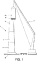
Figure 1 . - Shows a schematic view of a particular embodiment wherein the tower comprises stackable sections and a crane is stacking a section onto the lower sections. -
Figure 2 . - Shows a schematic view of a tower comprising four stacked sections wherein a crane is stacking the nacelle onto the top section. -
Figure 3 . - Shows a schematic view of a section along a vertical plane of two adjacent sections and a plan view of the lower section which shows a first embodiment of auxiliary connections of sections to each other. -
Figure 4 . - Shows a schematic view of a section along a vertical plane of two adjacent sections and a plan view of the lower section which shows a second embodiment of auxiliary connections of sections to each other. -
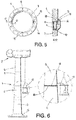
Figure 5 . - Shows a schematic view of a section along a vertical plane of two adjacent sections and a plan view of the lower section which shows a third embodiment of auxiliary connections of sections to each other. -
Figure 6 . - Shows a schematic view of an embodiment of the main connections. - Next, a detailed description of a preferred embodiment of the present invention shall be provided, with the help of the above referred
figures 1-6 - The invention relates, according to a first aspect thereof, to an assembly method for a wind turbine comprising a tower (1), a nacelle (2) and a rotor. The tower (1) is of the type comprising stackable annular sections (3, 4, 5, 6), wherein at least two of the annular sections (3, 4, 5, 6), e.g. a first (3) and a second (4) annular sections, are made of concrete.
- This method can be applied to any wind-turbine tower (1) regardless the number of concrete annular sections that it comprises.
- The annular sections (3, 4, 5, 6) may comprise, besides first (3) and second (4) annular sections, at least one further annular section (5, 6), made of concrete. The tower (1) may additionally comprise other annular sections (not shown in the figures) which are not made of concrete but, for example are made of steel.
- The method of the invention relates to stacking, upon the first annular section (3), the second annular section (4) and, once the second annular section is stacked, connecting the first annular section (3) to the second annular section (4) by means of performing auxiliary connections capable of withstanding seismic loads induced by an earthquake, for allowing the tower (1) to withstand loads induced by an earthquake that may occur during assembling.
- When the tower (1) comprises the further annular sections (5, 6) made of concrete, the invention relates to a repetitive method, wherein all concrete annular sections (3, 4, 5, 6) are consecutively stacked upon each other, i.e. the third annular section (5) is stacked upon the second annular section (4), the fourth annular section (6) is stacked upon the third annular section (5), and so on, until all concrete annular sections (3, 4, 5, 6) are stacked. Then, if the tower (1) comprises the above-referred non-concrete annular section, these are stacked upon the concrete annular sections (3, 4, 5, 6). Finally, the nacelle (2) and the rotor are mounted atop of all stacked annular sections, whether concrete or non-concrete.
-
Figure 1 shows part of the assembly method of the invention. By means of a lifting and positioning means (7), such as a crane (7), all annular sections (3, 4, 5, 6) of the tower (1) are lifted and positioned in a stacked manner. - For connecting the annular sections (3, 4, 5, 6) to each other, auxiliary connections are provided, performed by auxiliary connection means, and which are intended to withstand seismic loads induced by an earthquake, for allowing the tower to withstand loads induced by an earthquake that may occur during the assembling. According to a preferred embodiment, the auxiliary connections may further be intended to withstand loads induced by the wind on the wind turbine in absence of the rotor, but not loads induced by the rotor and the wind in the rotor. According to a more preferred embodiment, the auxiliary connections may be further intended to withstand loads induced by the wind on the wind turbine including the rotor, preferably with the blades in a feathered position. More preferably with the blades in a feathered position when the wind turbine is not operating. In the feathered position, the blades do not barely offer any resistance to the wind, therefore the rotor is freely rotatable, although much slower than in operation, so that the loads in the feathered position are much lower that the operation loads.
- The auxiliary connections, besides withstanding loads induced by the wind on the wind turbine, including the rotor with the blades in a feathered position, are capable of transmitting self-weight loads and loads induced by an earthquake to the base of the tower (1), withstanding not only compression stress but also bending, tensile and shear stress and enabling loads to be withstood during the assembly. According to the above, the auxiliary connections, when properly dimensioned, allow the rotor to be mounted using the same crane (7) without needing to previously perform the main connections, which would be performed later, thereby releasing the crane (7) for mounting another wind turbine or being dismantled.
- The method of the invention stands out in that the auxiliary connections for the first (3) and the second annular section (4) are performed before any other annular section, whether concrete or non-concrete, is stacked upon the second annular section (4).
- In the case wherein the tower (1) comprises the further concrete annular sections (5, 6), auxiliary connections are also performed after each concrete annular section (4, 5, 6) is stacked, but before any next annular section (whether concrete or non-concrete) or the nacelle, are stacked.
- In particular, in the following steps of the method, after the first (3) and the second (4) annular sections have been stacked and auxiliary connections have already been performed for connecting the second (4) and the first (3) annular sections to each other, the steps of stacking and performing auxiliary connections are performed for any further annular concrete section (5, 6), so that the auxiliary connections still allow the connected sections (4, 5, 6) to withstand loads induced by an earthquake that may occur during the assembly. This step is repeated with the rest of the concrete annular sections (5, 6) until all concrete annular sections (3, 4, 5, 6) are stacked upon each other.
- What is intended by performing auxiliary connections immediately after stacking each annular section (3, 4, 5), but before any next annular sections or the nacelle is stacked, is finding a balance between, on one side, a reduced time-consuming assembly method of the wind turbine and, on the other side, a lower risk of the wind turbine collapsing in case of an eventual earthquake during the assembling thereof. Also, once the tower (1) is securely assembled and comprises all the required auxiliary connections performed, the use of the large-tonnage crane (7) is no longer necessary, since the auxiliary connections ensure that the tower (1) will not to be damaged nor collapse due to potential earthquakes. Therefore, the crane (7) may be moved to another location and devoted to other assembly tasks in other wind turbines within the wind farm. Thus, the time of use of the large-tonnage crane (7) is reduced when constructing a tower (1) or a set of towers (1) with this method.
- Besides the above-referred auxiliary connections, each pair of adjacent annular sections (3, 4, 5, 6) are further connected to each other, as well as a top annular section, whether concrete or non-concrete, and which is stacked atop of all stacked annular sections, is connected to the nacelle (2), by means of main connections, which are intended to withstand all operation loads induced by the wind (and possible earthquakes) on the wind turbine including the rotor.
- According to a preferred embodiment, the main connection connecting the nacelle (2) to the top annular section is performed before performing any of the main connections connecting the annular sections (3, 4, 5, 6) to each other, wherein the main connections connecting annular sections (3, 4, 5, 6) located upwardly are performed before those for annular sections (3, 4, 5, 6) located near the bottom due to the upper sections have a greater possibility of overturning in case of earthquakes. Alternatively, the main connections may be performed beginning with a bottom part of the tower (1), i.e., first the main connection connecting the first annular section (3) to the second annular section (4), and then the main connection connecting the second annular sections (4) to the third annular section (5) and so on.
-
Figure 2 represents a step of the method object of the invention wherein, by means of the crane (7), the nacelle (2) is lifted and positioned onto the top annular section. Later a main connection must be performed for connecting the nacelle (2) and the upper annular section (6). Finally, main connections are performed for connecting all the concrete annular sections (3, 4, 5, 6) to each other by means of main connecting means. - Also preferably, the auxiliary connections are further configured to acquire a first resistance level needed to withstand loads induced by an earthquake in a first time and the main connections are configured to acquire a second resistance level needed to withstand all the operation loads of the wind turbine in a second time, longer than the first time.
- As explained above, at least the first (3) and the second (4) annular sections are made of concrete. Preferably, one, some or all, of the further annular sections (5, 6) are also made of concrete. In particular, the top annular section (6) may also be made of concrete. However, as an alternative, the tower (1) may comprise other annular sections not made of concrete but, for instance, selected types of steel, the annular sections (3, 4, 5, 6) made of concrete occupying the lower position, wherein the annular sections not made of concrete would be stacked upon the annular sections (3, 4, 5, 6) made of concrete.
- According to a preferred embodiment for performing the auxiliary connections, see
figure 3 , the first annular section (3) comprises housings (9), located in an upper flange of the first annular section (3), and the second annular section (4) comprises bars (8) emanating at least from a lower flange of the second annular section (4). The housings (9) of the first annular section (3) are configured to allocate the bars (8) of the second annular section (4), for defining bar (8)-housing (9) assemblies wherein the bars (8) are inserted into the housings (9). In general, for each pair of adjacent annular sections (3, 4, 5, 6) made of concrete, one of the adjacent annular sections (3, 4, 5, 6), referred to as upper annular section (4, 5, 6) is stacked upon the other adjacent annular section (3, 4, 5, 6), referred to as lower annular section (3, 4, 5), wherein the upper annular section (4, 5, 6) has bars (8) as explained above for the second annular section (4), whereas the lower annular section (3, 4, 5) has housings (9) as explained above for the first annular section (3). -
Figure 3 also shows the connection between a lower and an upper annular sections, specifically first (3) and second (4) annular sections. Once the bars (8) have been introduced into the housings (9), the auxiliary connections are later performed. - Preferably, the housings (9) are distributed homogeneously along the upper flange of each lower annular section (3, 4, 5); for instance, the housings (9) are located perimetrally, at a uniform angular spacing, as seen on
figures 3-5 . - For performing the auxiliary connections, once the upper annular section has been stacked over the lower annular section, and always before stacking another annular section over the upper annular section, the resin (11) is inserted (preferably poured) in at least one of the housings (9) of the lower annular section (3, 4, 5). In particular, resin (11) may be inserted so that some or all of the housings (9) are partially or totally filled with resin (11). Preferably, only some, but not all, of the housings (9), for instance, between 20 % and 40%, are partially or completely filled with resin (11). The housings (9) which are filled with resin (11) are preferably filled up to 30%, more preferably up to 40 %, of the volume of the housings (9). The resin (11) is preferably inserted in non-contiguous housings (9), see
figure 3 . - As a result of the resin (11) having been hardened, a temporary anchor is achieved. This ensures that the bars (8) withstand bending (flexion) stress during the assembly of the wind turbine in the case of lateral loads due to the effect of eventual earthquakes.
- Stacking an annular section (4, 5, 6) upon a previously mounted annular section (3, 4, 5) may take a stacking time of
approximatively 3 hours. According to a preferred embodiment, performing any auxiliary connection takes a time which is shorter than the stacking time, so that the assembling of the wind turbine is not delayed by performing the auxiliary connections. The time taken for performing an auxiliary connection may be preselected by, for instance, selecting an appropriate kind of resin (11). - Preferably, by way of example, the step of partially filling with resin (11) in some or all the housings (9) takes a first predetermined time which is preferably 40 minutes or less, more preferably 30 minutes or less. Later, a second predetermined time after the housing (9) is partially filled, for allowing the resin (11) to cure, may be waited, before stacking the third annular section (5) or the nacelle (2) upon the second annular section (4). As explained above, the combined duration of the first and the second predetermined times is preferably less than the stacking time, preferably less than three hours.
- The partial application of resin (11) in the housings (9) of each annular concrete section (3, 4, 5, 6), as explained above, is preferably done in a time shorter than or equal to the first pre-set time of application of the resin (11) in order to reduce the possibility of the tower (1) collapsing in the eventual occurrence of an earthquake and also in order to reduce the spectrum of loads that the auxiliary connection has to withstand; if the application of resin (11) takes more time, the exposure time increases, and the greater the exposure time the higher the probability of having an earthquake of a greater magnitude. This is achieved because the auxiliary connections enable the tower (1) to withstand the loads that may suffer the structure in such an event. In this sense, the sooner the auxiliary connections are finished, the lower the exposure time of the annular sections (3, 4, 5, 6) to a potential earthquake without safe connections.
- For performing the main connections between adjacent annular sections (3, 4, 5, 6), the housings (9) that are partially filled with resin (11) are completed later by totally being filled with grout (10). Additionally, grout (10) is inserted in the (empty) housings (9) wherein resin (11) has not been inserted. According to a preferred embodiment, performing the main connections may comprise a further stage of inserting (for example, pouring) grout (10), or a functionally equivalent product, for filling the gap (18) that exists between each pair of consecutively-stacked annular sections (3, 4, 5, 6). Concrete may be used instead or grout (10). Resin (11) may also be used instead of grout (10).
- As it has been mentioned before, later on, by performing the main connections, a final connection will be achieved by filling with grout (10) the remaining empty volume in the housings (9), i.e.the volume not filled with resin (10), so that all the bars (8) substantially withstand the same loads.
-
Figure 3 shows an embodiment in which, after the execution of the main connections, some of the housings (9) will comprise resin (11) in a lower area and grout (10) in the upper area, and the gap (18) that exists between the two adjacent annular sections (specifically the first (3) and the second (4) annular sections) is filled with grout (10). - Performing the main connections connecting the nacelle (2) and the top annular section (6) to each other may comprise fastening the nacelle (2) and the top annular section (6) with retaining elements.
-
Figure 4 shows a second embodiment of the auxiliary connections. According to such embodiment, at a lower part of at least one of the housings (9) there is a recess (12) which is open towards the interior of the lower annular section (3, 4, 5), so that the step of performing the auxiliary connections comprises the following stages: - accessing the bars (8) of the upper annular section (4, 5, 6) through the recesses (12) of the lower annular section (3, 4, 5), and
- fastening a retaining element (13) to the bar (8) within the recess (12).
- Main connections show grout (10) inserted in the housings (9) and in the gap (18) that exists between the two adjacent annular sections.
-
Figure 5 shows an alternative embodiment for the auxiliary connections wherein lugs (14, 15) and dowel rods (16) are used. According to such an embodiment, the auxiliary connections may be performed by means of first lugs (14) which are integral with, or attached to, the upper flange of the lower annular section (3, 4, 5), and second lugs (15) which are integral with, or attached to, the lower flange of the upper annular section (4, 5, 6), so that the performing of the auxiliary connections comprises the stages of: - connecting the first lugs (14) to the second lugs (15) by interposing dowel rods (16) therebetween, and
- blocking the dowel rods (16).
- Said lugs (14, 15) can be positioned and fixed to the walls of the annular sections (3, 4, 5, 6) in a factory at the time of manufacture thereof, or alternatively performed on site when assembling the wind turbine. Preferably, and for each connection, one of the first lugs (14) is factory-fixed to one of the sections (3) and another one of the second lugs (15) is fixed to the adjacent section (4) when assembling the tower (1), allowing adjustment of the position to ensure contact of the planes of any first lug (14) and corresponding second lug (15). Thus, the problems of tolerances in components of large dimensions are overcome.
- Main connections show grout (10) inserted in the housings (9) and in the gap (18) that exists between the two adjacent annular sections.
- The method for performing the auxiliary connections involving annular sections (3, 4, 5, 6) of the tower (1), according to the invention, is time-wise far less costly than performing the main connections involving said annular sections (3, 4, 5, 6). Thus, the operating time of the crane (7), which is a high-tonnage crane (7), can be reduced, as the components of the wind turbine including nacelle (2) and tower (1) will be safely connected through connections that enable the assembly to stand the loads related to phenomenon that may occur during the assembly stage. Later, the main connections required for standing all the operational loads of the wind turbine and hence performed before turning on the wind turbine so that it can start generating power, can be performed using other means different than the high-tonnage crane (7).
- The speed of execution of the auxiliary connections enables the entire process to be performed continuously using a single crane (7) and thus reduce the operating time of the high-tonnage crane (7) for the assembly of the wind turbine. Said crane (7) can be used once the auxiliary connections are performed and all the heavy components stacked to assemble another wind turbine in the wind farm.
- Taking into account the properties of the resin (11) and grout (10), mainly Young's modulus (E), and establishing an adequate ratio between the dimensions of the areas that include resin (11) and the dimensions of the areas that includes grout (10), suitable properties of strength of the final union are reached. In general, the Young's modulus (E) achieved by the resin (11) is lower than that achieved by the grout (10), so that if the whole housings (9) were filled only with resin (11), the bars (8) inserted into these housings (9) would withstand lower load than the bars (8) inserted in those housings (9) filled only with grout (10). In one embodiment, the dimension of the area of the housing (9) including resin (11) is less than 50% of the total volume of the housing (9). In this way, the bars (8) that are inserted in these housings (9), after being completely filled with grout (10) and after the grout (10) has set, work similarly to the rest of the bars (8) inserted in housings (9) filled only with grout (10) despite the different properties (Young modulus) of resin and grout. The total time required for carrying out the main connections is the sum of that required to perform the grout (10) injection, plus the time required for the grout (10) to cure in each of the main connections. Therefore, the total execution time of main connections amounts to over 24 hours in general, often being over 48 or even 72 hours.
- Once all the main connections have been performed, the rotor is placed, and the wind turbine is capable of withstanding all operational loads induced by said rotor once in operation (due to the wind acting on the surface of the blades and the rotor's own weight).
-
Figure 6 shows an embodiment for accessing the joints between the concrete annular sections (3, 4, 5, 6) and for performing the main connections, wherein lifting means are used which comprise a hanging platform (17) suspended from the nacelle (2) or from the upper section (6) of the tower (1), thus avoiding the use of large cranes (7) or intermediate platforms. - Preferably, the tower (1) is a frustoconical tower (1).
- Below, a table is shown, indicating, as a percentage, a ratio of the number of housings (9) filled with resin (11) with respect to the total number of housings (9) for each annular section, as a function of the height at which the annular section is located. As can be observed, there are 6 annular sections defining 5 joints. The total volume filled of the set of housings (9) decreases as the height is increased, however in the annular section (5) immediately below the upper annular section (6), corresponding to a height of 100 m, it increases. The lowest line of the chart (TOTAL) indicates the percentage ratio of the housings (9) filled with resin (11) with respect to the total number of housings (9) for the whole tower (1).
H(m) % 100 27 80 25 60 27 40 35 20 39 TOTAL 30 - The connection for connecting the lowest annular section and the foundation (19), and the connection for connecting the top annular section (6) (the highest section) and the nacelle (2) are main connections, do not make use of auxiliary connections.
- The invention also relates, according to a second aspect, to a wind turbine comprising a tower (1), a nacelle (2) and a rotor, wherein the wind turbine is assembled according to the method described above.
Claims (20)
- Method for assembling a wind turbine, wherein the wind turbine comprises a tower (1), a nacelle (2) and a rotor, the tower (1) comprising stackable annular sections (3, 4, 5, 6), wherein the method comprises the following steps:- stacking, upon a first annular section (3), a second annular section (4), by using lifting and positioning means (7);- performing auxiliary connections for connecting the first (3) and the second (4) annular sections to each other by using auxiliary connecting means,the method being characterized in that the auxiliary connections are performed prior to stacking a third annular section (5) or another wind turbine component upon the second annular section (4), wherein the auxiliary connections are further configured to withstand seismic loads induced by an earthquake.
- Method according to claim 1, characterized in that it further comprises the steps of:- once the auxiliary connections for connecting the first annular section (3) to the second annular section (4) have been performed, stacking, upon the second annular section (4), the third annular section (5), by using the lifting and positioning means (7), so that the third annular section (5) stays atop of all stacked annular sections (3, 4, 5);- performing auxiliary connections for connecting the stacked third annular section (5) to the second annular section (4); and- repeating the above referred two steps, so that a plurality of annular sections (5, 6) are stacked upon each other, and corresponding auxiliary connections for connecting any two consecutively stacked annular sections (4, 5, 6) are performed, wherein the auxiliary connections are performed before stacking another annular section.
- Method according to any of claims 1-2, characterized in that it further comprises stacking the nacelle above all stacked annular sections (3, 4, 5, 6), wherein the auxiliary connections are further configured to withstand loads induced by the wind on the wind turbine in absence of the rotor.
- Method according to claim 3, characterized in that it further comprises attaching the rotor to the nacelle, wherein the auxiliary connections are further configured to withstand loads induced by the wind on the wind turbine including the rotor with the blades in a feathered position.
- Method according to any of claims 1-4, characterized in that it further comprises a step of performing main connections for connecting the first (3) and the second (4) annular sections to each other intended to withstand all operation loads induced by the wind on the wind turbine including the rotor.
- Method according to claims 2 and 5, characterized in that it further comprises the following steps:- performing main connections connecting any two adjacent annular sections (4, 5, 6) to each other; and- performing a main connection connecting the nacelle (2) and the top annular section (6) to each other;wherein one main connection of the main connections, connecting the nacelle (2) and the top annular section (6) to each other is performed before performing the main connections connecting any two adjacent annular sections (4, 5, 6) to each other.
- Method according to any of claims 5 and 6, characterized in that the auxiliary connections are further configured to acquire a first resistance level needed to withstand loads induced by an earthquake in a first time and the main connections are configured to acquire a second resistance level needed to withstand all the operation loads of the wind turbine in a second time longer than the first time.
- Method according to any of the previous claims, characterized in that at least the first (3) and second (4) annular sections are made of concrete.
- Method according to any of claims 2-8, characterized in that, for performing the first auxiliary connections, one lower annular section of each pair of annular sections connected by auxiliary connections comprises an upper flange with housings (9), wherein one upper annular section (4) comprises a lower flange wherefrom bars (8) emanate, so that the housings (9) are configured to allocate the bars (8), defining bar (8)-housing (9) assemblies.
- Method according to claim 9, characterized in that the step of performing the auxiliary connections comprises anyone of the following:- partially or completely filling with resin (11) only some of the housings (9); or- partially or completely filling with resin (11) all the housings (9).
- Method according to claim 10, characterized in that a number of filled housings (9), which is lower than the total number of housings (9) located in the upper flange of the first annular section (3), is filled at least partially with resin (11).
- Method according to any of claims 10-11, characterized in that the step of performing the main connections for connecting the first annular section (3) and the second annular section (4) to each other comprise completing the filling of the housings (9) that already comprise resin (11) with grout (10) and/or filling with grout (10) the housings (9) that have not been filled with resin (11).
- Method according to claim 12, characterized in that the performing of the main connections further comprises filling with grout (10) a gap (18) left between the first (3) and the second (4) annular sections.
- Method according to claim 9, characterized in that the housings (9) are distributed homogeneously along the upper flange of the annular sections (3, 4, 5, 6).
- Method according to any of claims 12-14, characterized in that the step of partially filling some or all the housings (9) with resin (11) takes a first predetermined time which is preferably 40 minutes or less, more preferably 30 minutes or less.
- Method according to claim 15, characterized in that further comprises a step of waiting a second predetermined time after the resin (11) is partially filled, for allowing the resin (11) to cure, before stacking the third annular section (5) or the nacelle (2) upon the second annular section (4).
- Method according to claim 16, characterized in that the combined duration of the first predetermined time plus the second predetermined time is lower than a stacking time necessary for stacking an annular section (4, 5, 6) upon a previously mounted annular section (3, 4, 5), preferably less than 3 hours.
- Method according to claim 9, characterized in that at a lower part of at least one of the housings (9) there is a recess (12) which is open towards the interior of the lower annular section (3, 4, 5), so that the step of performing the auxiliary connections comprises the following stages:- accessing the bars (8) of the upper annular section (4, 5, 6) through the recesses (12) of the lower annular section (3) and- fastening a retaining element (13) to the bar (8) within the recess (12).
- Method according to claim 9, characterized in that, first lugs (14) are attached to, or integral with, the upper flange of the lower annular section (3, 4, 5), as well as and second lugs (15) are attached to, or integral with, the lower flange of the upper annular section (4, 5, 6), so that performing the auxiliary connections comprises the stages of:- connecting the first lugs (14) to the second lugs (15) by interposing dowel rods (16) therebetween, and- blocking the dowel rods (16).
- Wind turbine comprising a tower (1), a nacelle (2) and a rotor, characterized in that the wind turbine is assembled according to the method of any of the preceding claims.
Priority Applications (5)
| Application Number | Priority Date | Filing Date | Title |
|---|---|---|---|
| ES18382969T ES2979263T3 (en) | 2018-12-21 | 2018-12-21 | Method for assembling a wind turbine and wind turbine assembled according to said method |
| DK18382969.6T DK3670899T3 (en) | 2018-12-21 | 2018-12-21 | PROCEDURE FOR ASSEMBLY OF A WINDMILL AND WINDMILL ASSEMBLED ON THE BASIS OF THE PROCEDURE |
| EP18382969.6A EP3670899B1 (en) | 2018-12-21 | 2018-12-21 | Method for assembling a wind turbine and wind turbine assembled according to said method |
| US16/707,676 US11821403B2 (en) | 2018-12-21 | 2019-12-09 | Method for assembling a wind turbine and wind turbine assembled according to said method |
| CL2019003797A CL2019003797A1 (en) | 2018-12-21 | 2019-12-20 | Method for mounting a wind turbine and generator assembled according to said method |
Applications Claiming Priority (1)
| Application Number | Priority Date | Filing Date | Title |
|---|---|---|---|
| EP18382969.6A EP3670899B1 (en) | 2018-12-21 | 2018-12-21 | Method for assembling a wind turbine and wind turbine assembled according to said method |
Publications (2)
| Publication Number | Publication Date |
|---|---|
| EP3670899A1 true EP3670899A1 (en) | 2020-06-24 |
| EP3670899B1 EP3670899B1 (en) | 2024-03-13 |
Family
ID=65010503
Family Applications (1)
| Application Number | Title | Priority Date | Filing Date |
|---|---|---|---|
| EP18382969.6A Active EP3670899B1 (en) | 2018-12-21 | 2018-12-21 | Method for assembling a wind turbine and wind turbine assembled according to said method |
Country Status (5)
| Country | Link |
|---|---|
| US (1) | US11821403B2 (en) |
| EP (1) | EP3670899B1 (en) |
| CL (1) | CL2019003797A1 (en) |
| DK (1) | DK3670899T3 (en) |
| ES (1) | ES2979263T3 (en) |
Families Citing this family (7)
| Publication number | Priority date | Publication date | Assignee | Title |
|---|---|---|---|---|
| CN107620680B (en) * | 2017-09-11 | 2018-10-23 | 北京金风科创风电设备有限公司 | Streamlined body for inhibiting vibration of enclosure structure, equipment and method for hoisting tower drum |
| CN113279917B (en) | 2020-02-20 | 2023-03-03 | 江苏金风科技有限公司 | Tower sections and wind turbines |
| WO2022258119A1 (en) * | 2021-06-07 | 2022-12-15 | Vestas Wind Systems A/S | System and method for assembling a wind turbine |
| ES2938008B2 (en) * | 2021-10-01 | 2024-04-16 | Esteyco S A | INSTALLATION PROCEDURE OF A TOWER AND TOWER INSTALLED WITH SUCH PROCEDURE |
| EP4343145A1 (en) * | 2023-06-21 | 2024-03-27 | Nordex Energy Spain, S.A.U. | Set of concrete segments of adjacent sections of a wind turbine tower, and method of assembling a wind turbine |
| EP4481144A1 (en) * | 2023-06-23 | 2024-12-25 | Nordex Energy Spain, S.A.U. | Concrete segment of a section of a wind turbine tower, set of a concrete segment and heating means, concrete section, wind turbine, mould and method of assembling the wind turbine |
| EP4530422A1 (en) * | 2023-09-26 | 2025-04-02 | Nordex Energy Spain, S.A.U. | Concrete segment of a section of a wind turbine tower, mould configured to cast a concrete segment |
Citations (2)
| Publication number | Priority date | Publication date | Assignee | Title |
|---|---|---|---|---|
| EP2541047A2 (en) | 2011-06-30 | 2013-01-02 | Acciona Windpower S.a. | Wind turbine assembling method and wind turbine assembled according to said method |
| US20140298737A1 (en) * | 2011-06-09 | 2014-10-09 | Esteyco Energia S.L. | Socket-projection fixing assembly |
Family Cites Families (6)
| Publication number | Priority date | Publication date | Assignee | Title |
|---|---|---|---|---|
| DE102007031065B4 (en) * | 2007-06-28 | 2011-05-05 | Nordex Energy Gmbh | Wind turbine tower |
| PT2253782E (en) * | 2009-05-19 | 2013-11-18 | Pacadar Sa | Support structure for a wind turbine |
| SE535860C2 (en) * | 2010-02-09 | 2013-01-15 | Erigovis Ab | Procedure for producing a tower for a wind turbine |
| DE102010039796A1 (en) * | 2010-06-14 | 2011-12-15 | Max Bögl Bauunternehmung GmbH & Co. KG | Tower with an adapter piece and method of making a tower with an adapter piece |
| GB201215004D0 (en) * | 2012-08-23 | 2012-10-10 | Blade Dynamics Ltd | Wind turbine tower |
| WO2015131174A1 (en) * | 2014-02-28 | 2015-09-03 | University Of Maine System Board Of Trustees | Hybrid concrete - composite tower for a wind turbine |
-
2018
- 2018-12-21 DK DK18382969.6T patent/DK3670899T3/en active
- 2018-12-21 EP EP18382969.6A patent/EP3670899B1/en active Active
- 2018-12-21 ES ES18382969T patent/ES2979263T3/en active Active
-
2019
- 2019-12-09 US US16/707,676 patent/US11821403B2/en active Active
- 2019-12-20 CL CL2019003797A patent/CL2019003797A1/en unknown
Patent Citations (2)
| Publication number | Priority date | Publication date | Assignee | Title |
|---|---|---|---|---|
| US20140298737A1 (en) * | 2011-06-09 | 2014-10-09 | Esteyco Energia S.L. | Socket-projection fixing assembly |
| EP2541047A2 (en) | 2011-06-30 | 2013-01-02 | Acciona Windpower S.a. | Wind turbine assembling method and wind turbine assembled according to said method |
Also Published As
| Publication number | Publication date |
|---|---|
| ES2979263T3 (en) | 2024-09-25 |
| EP3670899B1 (en) | 2024-03-13 |
| CL2019003797A1 (en) | 2020-12-11 |
| US11821403B2 (en) | 2023-11-21 |
| US20200200148A1 (en) | 2020-06-25 |
| DK3670899T3 (en) | 2024-05-27 |
Similar Documents
| Publication | Publication Date | Title |
|---|---|---|
| EP3670899B1 (en) | Method for assembling a wind turbine and wind turbine assembled according to said method | |
| EP2541047B1 (en) | Wind turbine assembling method and wind turbine assembled according to said method | |
| EP2374966B1 (en) | Method of building a hybrid tower for a wind generator | |
| AU2019300467B2 (en) | Foundation for a wind turbine | |
| EP3467304B1 (en) | Tower section for automatically raising a wind turbine and automatic raising method for same | |
| FI3516121T3 (en) | Foundation for a wind turbine | |
| US10738499B2 (en) | Concrete towers manufacturing method for wind turbines and concrete tower for wind turbine | |
| WO2017039923A2 (en) | Equipment tower having a concrete plinth | |
| JP6638140B2 (en) | Basic structure of tower structure | |
| EP3910195B1 (en) | Tower section arrangement for a guyed tower of a wind turbine, guyed wind turbine tower, wind turbine and method for assembling a wind turbine | |
| WO2023126974A1 (en) | Portable footing based telecom tower | |
| JP7486187B2 (en) | How to dismantle tower-type wind power generation equipment | |
| KR20100109458A (en) | The foundation design for the tower shaped structure | |
| JP7409720B2 (en) | How to dismantle tower-type wind power generation equipment | |
| RU2782228C2 (en) | Foundation for wind power plant | |
| EP3246493A1 (en) | A method for construction of a mast for a windmill | |
| EP3401445B1 (en) | Anchoring section for a foundation structure | |
| AU2011201502B8 (en) | Method of building a hybrid tower for a wind generator | |
| JPH02140372A (en) | Iron tower pushing-up construction method | |
| CN120584230A (en) | Wind turbine self-lifting system and assembly method | |
| JP2023034844A (en) | Inversion method of tower-like building | |
| WO2019086137A1 (en) | Method for erecting a tower comprising a multi-part tower section and sub-section of a multi-part tower section of a tower |
Legal Events
| Date | Code | Title | Description |
|---|---|---|---|
| PUAI | Public reference made under article 153(3) epc to a published international application that has entered the european phase |
Free format text: ORIGINAL CODE: 0009012 |
|
| STAA | Information on the status of an ep patent application or granted ep patent |
Free format text: STATUS: THE APPLICATION HAS BEEN PUBLISHED |
|
| AK | Designated contracting states |
Kind code of ref document: A1 Designated state(s): AL AT BE BG CH CY CZ DE DK EE ES FI FR GB GR HR HU IE IS IT LI LT LU LV MC MK MT NL NO PL PT RO RS SE SI SK SM TR |
|
| AX | Request for extension of the european patent |
Extension state: BA ME |
|
| STAA | Information on the status of an ep patent application or granted ep patent |
Free format text: STATUS: REQUEST FOR EXAMINATION WAS MADE |
|
| 17P | Request for examination filed |
Effective date: 20201223 |
|
| RBV | Designated contracting states (corrected) |
Designated state(s): AL AT BE BG CH CY CZ DE DK EE ES FI FR GB GR HR HU IE IS IT LI LT LU LV MC MK MT NL NO PL PT RO RS SE SI SK SM TR |
|
| STAA | Information on the status of an ep patent application or granted ep patent |
Free format text: STATUS: EXAMINATION IS IN PROGRESS |
|
| 17Q | First examination report despatched |
Effective date: 20220714 |
|
| P01 | Opt-out of the competence of the unified patent court (upc) registered |
Effective date: 20230530 |
|
| GRAP | Despatch of communication of intention to grant a patent |
Free format text: ORIGINAL CODE: EPIDOSNIGR1 |
|
| STAA | Information on the status of an ep patent application or granted ep patent |
Free format text: STATUS: GRANT OF PATENT IS INTENDED |
|
| RIC1 | Information provided on ipc code assigned before grant |
Ipc: E04H 12/34 20060101ALI20230927BHEP Ipc: E04H 12/12 20060101ALI20230927BHEP Ipc: F03D 13/20 20160101ALI20230927BHEP Ipc: F03D 13/10 20160101AFI20230927BHEP |
|
| INTG | Intention to grant announced |
Effective date: 20231019 |
|
| GRAS | Grant fee paid |
Free format text: ORIGINAL CODE: EPIDOSNIGR3 |
|
| GRAA | (expected) grant |
Free format text: ORIGINAL CODE: 0009210 |
|
| STAA | Information on the status of an ep patent application or granted ep patent |
Free format text: STATUS: THE PATENT HAS BEEN GRANTED |
|
| AK | Designated contracting states |
Kind code of ref document: B1 Designated state(s): AL AT BE BG CH CY CZ DE DK EE ES FI FR GB GR HR HU IE IS IT LI LT LU LV MC MK MT NL NO PL PT RO RS SE SI SK SM TR |
|
| REG | Reference to a national code |
Ref country code: GB Ref legal event code: FG4D |
|
| REG | Reference to a national code |
Ref country code: CH Ref legal event code: EP |
|
| REG | Reference to a national code |
Ref country code: DE Ref legal event code: R096 Ref document number: 602018066524 Country of ref document: DE |
|
| REG | Reference to a national code |
Ref country code: IE Ref legal event code: FG4D |
|
| REG | Reference to a national code |
Ref country code: DK Ref legal event code: T3 Effective date: 20240524 |
|
| PG25 | Lapsed in a contracting state [announced via postgrant information from national office to epo] |
Ref country code: LT Free format text: LAPSE BECAUSE OF FAILURE TO SUBMIT A TRANSLATION OF THE DESCRIPTION OR TO PAY THE FEE WITHIN THE PRESCRIBED TIME-LIMIT Effective date: 20240313 |
|
| REG | Reference to a national code |
Ref country code: LT Ref legal event code: MG9D |
|
| REG | Reference to a national code |
Ref country code: NL Ref legal event code: MP Effective date: 20240313 |
|
| PG25 | Lapsed in a contracting state [announced via postgrant information from national office to epo] |
Ref country code: RS Free format text: LAPSE BECAUSE OF FAILURE TO SUBMIT A TRANSLATION OF THE DESCRIPTION OR TO PAY THE FEE WITHIN THE PRESCRIBED TIME-LIMIT Effective date: 20240613 Ref country code: HR Free format text: LAPSE BECAUSE OF FAILURE TO SUBMIT A TRANSLATION OF THE DESCRIPTION OR TO PAY THE FEE WITHIN THE PRESCRIBED TIME-LIMIT Effective date: 20240313 |
|
| REG | Reference to a national code |
Ref country code: GR Ref legal event code: EP Ref document number: 20240401260 Country of ref document: GR Effective date: 20240716 |
|
| PG25 | Lapsed in a contracting state [announced via postgrant information from national office to epo] |
Ref country code: RS Free format text: LAPSE BECAUSE OF FAILURE TO SUBMIT A TRANSLATION OF THE DESCRIPTION OR TO PAY THE FEE WITHIN THE PRESCRIBED TIME-LIMIT Effective date: 20240613 Ref country code: NO Free format text: LAPSE BECAUSE OF FAILURE TO SUBMIT A TRANSLATION OF THE DESCRIPTION OR TO PAY THE FEE WITHIN THE PRESCRIBED TIME-LIMIT Effective date: 20240613 Ref country code: LT Free format text: LAPSE BECAUSE OF FAILURE TO SUBMIT A TRANSLATION OF THE DESCRIPTION OR TO PAY THE FEE WITHIN THE PRESCRIBED TIME-LIMIT Effective date: 20240313 Ref country code: HR Free format text: LAPSE BECAUSE OF FAILURE TO SUBMIT A TRANSLATION OF THE DESCRIPTION OR TO PAY THE FEE WITHIN THE PRESCRIBED TIME-LIMIT Effective date: 20240313 Ref country code: FI Free format text: LAPSE BECAUSE OF FAILURE TO SUBMIT A TRANSLATION OF THE DESCRIPTION OR TO PAY THE FEE WITHIN THE PRESCRIBED TIME-LIMIT Effective date: 20240313 Ref country code: BG Free format text: LAPSE BECAUSE OF FAILURE TO SUBMIT A TRANSLATION OF THE DESCRIPTION OR TO PAY THE FEE WITHIN THE PRESCRIBED TIME-LIMIT Effective date: 20240313 |
|
| REG | Reference to a national code |
Ref country code: AT Ref legal event code: MK05 Ref document number: 1665981 Country of ref document: AT Kind code of ref document: T Effective date: 20240313 |
|
| PG25 | Lapsed in a contracting state [announced via postgrant information from national office to epo] |
Ref country code: SE Free format text: LAPSE BECAUSE OF FAILURE TO SUBMIT A TRANSLATION OF THE DESCRIPTION OR TO PAY THE FEE WITHIN THE PRESCRIBED TIME-LIMIT Effective date: 20240313 Ref country code: LV Free format text: LAPSE BECAUSE OF FAILURE TO SUBMIT A TRANSLATION OF THE DESCRIPTION OR TO PAY THE FEE WITHIN THE PRESCRIBED TIME-LIMIT Effective date: 20240313 |
|
| PG25 | Lapsed in a contracting state [announced via postgrant information from national office to epo] |
Ref country code: NL Free format text: LAPSE BECAUSE OF FAILURE TO SUBMIT A TRANSLATION OF THE DESCRIPTION OR TO PAY THE FEE WITHIN THE PRESCRIBED TIME-LIMIT Effective date: 20240313 |
|
| REG | Reference to a national code |
Ref country code: ES Ref legal event code: FG2A Ref document number: 2979263 Country of ref document: ES Kind code of ref document: T3 Effective date: 20240925 |
|
| PG25 | Lapsed in a contracting state [announced via postgrant information from national office to epo] |
Ref country code: NL Free format text: LAPSE BECAUSE OF FAILURE TO SUBMIT A TRANSLATION OF THE DESCRIPTION OR TO PAY THE FEE WITHIN THE PRESCRIBED TIME-LIMIT Effective date: 20240313 |
|
| PG25 | Lapsed in a contracting state [announced via postgrant information from national office to epo] |
Ref country code: IS Free format text: LAPSE BECAUSE OF FAILURE TO SUBMIT A TRANSLATION OF THE DESCRIPTION OR TO PAY THE FEE WITHIN THE PRESCRIBED TIME-LIMIT Effective date: 20240713 |
|
| PG25 | Lapsed in a contracting state [announced via postgrant information from national office to epo] |
Ref country code: SM Free format text: LAPSE BECAUSE OF FAILURE TO SUBMIT A TRANSLATION OF THE DESCRIPTION OR TO PAY THE FEE WITHIN THE PRESCRIBED TIME-LIMIT Effective date: 20240313 Ref country code: PT Free format text: LAPSE BECAUSE OF FAILURE TO SUBMIT A TRANSLATION OF THE DESCRIPTION OR TO PAY THE FEE WITHIN THE PRESCRIBED TIME-LIMIT Effective date: 20240715 |
|
| PG25 | Lapsed in a contracting state [announced via postgrant information from national office to epo] |
Ref country code: CZ Free format text: LAPSE BECAUSE OF FAILURE TO SUBMIT A TRANSLATION OF THE DESCRIPTION OR TO PAY THE FEE WITHIN THE PRESCRIBED TIME-LIMIT Effective date: 20240313 Ref country code: EE Free format text: LAPSE BECAUSE OF FAILURE TO SUBMIT A TRANSLATION OF THE DESCRIPTION OR TO PAY THE FEE WITHIN THE PRESCRIBED TIME-LIMIT Effective date: 20240313 |
|
| PG25 | Lapsed in a contracting state [announced via postgrant information from national office to epo] |
Ref country code: AT Free format text: LAPSE BECAUSE OF FAILURE TO SUBMIT A TRANSLATION OF THE DESCRIPTION OR TO PAY THE FEE WITHIN THE PRESCRIBED TIME-LIMIT Effective date: 20240313 |
|
| PG25 | Lapsed in a contracting state [announced via postgrant information from national office to epo] |
Ref country code: PL Free format text: LAPSE BECAUSE OF FAILURE TO SUBMIT A TRANSLATION OF THE DESCRIPTION OR TO PAY THE FEE WITHIN THE PRESCRIBED TIME-LIMIT Effective date: 20240313 |
|
| PG25 | Lapsed in a contracting state [announced via postgrant information from national office to epo] |
Ref country code: SK Free format text: LAPSE BECAUSE OF FAILURE TO SUBMIT A TRANSLATION OF THE DESCRIPTION OR TO PAY THE FEE WITHIN THE PRESCRIBED TIME-LIMIT Effective date: 20240313 |
|
| PG25 | Lapsed in a contracting state [announced via postgrant information from national office to epo] |
Ref country code: SM Free format text: LAPSE BECAUSE OF FAILURE TO SUBMIT A TRANSLATION OF THE DESCRIPTION OR TO PAY THE FEE WITHIN THE PRESCRIBED TIME-LIMIT Effective date: 20240313 Ref country code: SK Free format text: LAPSE BECAUSE OF FAILURE TO SUBMIT A TRANSLATION OF THE DESCRIPTION OR TO PAY THE FEE WITHIN THE PRESCRIBED TIME-LIMIT Effective date: 20240313 Ref country code: RO Free format text: LAPSE BECAUSE OF FAILURE TO SUBMIT A TRANSLATION OF THE DESCRIPTION OR TO PAY THE FEE WITHIN THE PRESCRIBED TIME-LIMIT Effective date: 20240313 Ref country code: PT Free format text: LAPSE BECAUSE OF FAILURE TO SUBMIT A TRANSLATION OF THE DESCRIPTION OR TO PAY THE FEE WITHIN THE PRESCRIBED TIME-LIMIT Effective date: 20240715 Ref country code: PL Free format text: LAPSE BECAUSE OF FAILURE TO SUBMIT A TRANSLATION OF THE DESCRIPTION OR TO PAY THE FEE WITHIN THE PRESCRIBED TIME-LIMIT Effective date: 20240313 Ref country code: IS Free format text: LAPSE BECAUSE OF FAILURE TO SUBMIT A TRANSLATION OF THE DESCRIPTION OR TO PAY THE FEE WITHIN THE PRESCRIBED TIME-LIMIT Effective date: 20240713 Ref country code: EE Free format text: LAPSE BECAUSE OF FAILURE TO SUBMIT A TRANSLATION OF THE DESCRIPTION OR TO PAY THE FEE WITHIN THE PRESCRIBED TIME-LIMIT Effective date: 20240313 Ref country code: CZ Free format text: LAPSE BECAUSE OF FAILURE TO SUBMIT A TRANSLATION OF THE DESCRIPTION OR TO PAY THE FEE WITHIN THE PRESCRIBED TIME-LIMIT Effective date: 20240313 Ref country code: AT Free format text: LAPSE BECAUSE OF FAILURE TO SUBMIT A TRANSLATION OF THE DESCRIPTION OR TO PAY THE FEE WITHIN THE PRESCRIBED TIME-LIMIT Effective date: 20240313 |
|
| REG | Reference to a national code |
Ref country code: DE Ref legal event code: R097 Ref document number: 602018066524 Country of ref document: DE |
|
| PLBE | No opposition filed within time limit |
Free format text: ORIGINAL CODE: 0009261 |
|
| STAA | Information on the status of an ep patent application or granted ep patent |
Free format text: STATUS: NO OPPOSITION FILED WITHIN TIME LIMIT |
|
| 26N | No opposition filed |
Effective date: 20241216 |
|
| PG25 | Lapsed in a contracting state [announced via postgrant information from national office to epo] |
Ref country code: SI Free format text: LAPSE BECAUSE OF FAILURE TO SUBMIT A TRANSLATION OF THE DESCRIPTION OR TO PAY THE FEE WITHIN THE PRESCRIBED TIME-LIMIT Effective date: 20240313 |
|
| PG25 | Lapsed in a contracting state [announced via postgrant information from national office to epo] |
Ref country code: MC Free format text: LAPSE BECAUSE OF FAILURE TO SUBMIT A TRANSLATION OF THE DESCRIPTION OR TO PAY THE FEE WITHIN THE PRESCRIBED TIME-LIMIT Effective date: 20240313 |
|
| REG | Reference to a national code |
Ref country code: CH Ref legal event code: PL |
|
| PG25 | Lapsed in a contracting state [announced via postgrant information from national office to epo] |
Ref country code: LU Free format text: LAPSE BECAUSE OF NON-PAYMENT OF DUE FEES Effective date: 20241221 |
|
| GBPC | Gb: european patent ceased through non-payment of renewal fee |
Effective date: 20241221 |
|
| REG | Reference to a national code |
Ref country code: BE Ref legal event code: MM Effective date: 20241231 |
|
| PG25 | Lapsed in a contracting state [announced via postgrant information from national office to epo] |
Ref country code: GB Free format text: LAPSE BECAUSE OF NON-PAYMENT OF DUE FEES Effective date: 20241221 Ref country code: BE Free format text: LAPSE BECAUSE OF NON-PAYMENT OF DUE FEES Effective date: 20241231 |
|
| PG25 | Lapsed in a contracting state [announced via postgrant information from national office to epo] |
Ref country code: FR Free format text: LAPSE BECAUSE OF NON-PAYMENT OF DUE FEES Effective date: 20241231 |
|
| PG25 | Lapsed in a contracting state [announced via postgrant information from national office to epo] |
Ref country code: CH Free format text: LAPSE BECAUSE OF NON-PAYMENT OF DUE FEES Effective date: 20241231 |
|
| PG25 | Lapsed in a contracting state [announced via postgrant information from national office to epo] |
Ref country code: IE Free format text: LAPSE BECAUSE OF NON-PAYMENT OF DUE FEES Effective date: 20241221 |
|
| PGFP | Annual fee paid to national office [announced via postgrant information from national office to epo] |
Ref country code: DK Payment date: 20251217 Year of fee payment: 8 |
|
| PGFP | Annual fee paid to national office [announced via postgrant information from national office to epo] |
Ref country code: GR Payment date: 20251215 Year of fee payment: 8 Ref country code: TR Payment date: 20251217 Year of fee payment: 8 |
|
| PGFP | Annual fee paid to national office [announced via postgrant information from national office to epo] |
Ref country code: ES Payment date: 20260119 Year of fee payment: 8 |
|
| PGFP | Annual fee paid to national office [announced via postgrant information from national office to epo] |
Ref country code: DE Payment date: 20251222 Year of fee payment: 8 |
|
| PGFP | Annual fee paid to national office [announced via postgrant information from national office to epo] |
Ref country code: IT Payment date: 20251231 Year of fee payment: 8 |