EP3670948B1 - Palier à roulement pourvu de bague d'arrêt radiale permettant de limiter la déformation radiale du palier à roulement - Google Patents
Palier à roulement pourvu de bague d'arrêt radiale permettant de limiter la déformation radiale du palier à roulement Download PDFInfo
- Publication number
- EP3670948B1 EP3670948B1 EP19217624.6A EP19217624A EP3670948B1 EP 3670948 B1 EP3670948 B1 EP 3670948B1 EP 19217624 A EP19217624 A EP 19217624A EP 3670948 B1 EP3670948 B1 EP 3670948B1
- Authority
- EP
- European Patent Office
- Prior art keywords
- ring
- rolling bearing
- bearing
- axial direction
- tongue
- Prior art date
- Legal status (The legal status is an assumption and is not a legal conclusion. Google has not performed a legal analysis and makes no representation as to the accuracy of the status listed.)
- Active
Links
Images

Classifications
-
- F—MECHANICAL ENGINEERING; LIGHTING; HEATING; WEAPONS; BLASTING
- F16—ENGINEERING ELEMENTS AND UNITS; GENERAL MEASURES FOR PRODUCING AND MAINTAINING EFFECTIVE FUNCTIONING OF MACHINES OR INSTALLATIONS; THERMAL INSULATION IN GENERAL
- F16C—SHAFTS; FLEXIBLE SHAFTS; ELEMENTS OR CRANKSHAFT MECHANISMS; ROTARY BODIES OTHER THAN GEARING ELEMENTS; BEARINGS
- F16C33/00—Parts of bearings; Special methods for making bearings or parts thereof
- F16C33/30—Parts of ball or roller bearings
- F16C33/58—Raceways; Race rings
- F16C33/583—Details of specific parts of races
- F16C33/586—Details of specific parts of races outside the space between the races, e.g. end faces or bore of inner ring
-
- F—MECHANICAL ENGINEERING; LIGHTING; HEATING; WEAPONS; BLASTING
- F16—ENGINEERING ELEMENTS AND UNITS; GENERAL MEASURES FOR PRODUCING AND MAINTAINING EFFECTIVE FUNCTIONING OF MACHINES OR INSTALLATIONS; THERMAL INSULATION IN GENERAL
- F16C—SHAFTS; FLEXIBLE SHAFTS; ELEMENTS OR CRANKSHAFT MECHANISMS; ROTARY BODIES OTHER THAN GEARING ELEMENTS; BEARINGS
- F16C19/00—Bearings with rolling contact, for exclusively rotary movement
- F16C19/52—Bearings with rolling contact, for exclusively rotary movement with devices affected by abnormal or undesired conditions
- F16C19/522—Bearings with rolling contact, for exclusively rotary movement with devices affected by abnormal or undesired conditions related to load on the bearing, e.g. bearings with load sensors or means to protect the bearing against overload
-
- F—MECHANICAL ENGINEERING; LIGHTING; HEATING; WEAPONS; BLASTING
- F16—ENGINEERING ELEMENTS AND UNITS; GENERAL MEASURES FOR PRODUCING AND MAINTAINING EFFECTIVE FUNCTIONING OF MACHINES OR INSTALLATIONS; THERMAL INSULATION IN GENERAL
- F16C—SHAFTS; FLEXIBLE SHAFTS; ELEMENTS OR CRANKSHAFT MECHANISMS; ROTARY BODIES OTHER THAN GEARING ELEMENTS; BEARINGS
- F16C33/00—Parts of bearings; Special methods for making bearings or parts thereof
- F16C33/30—Parts of ball or roller bearings
- F16C33/58—Raceways; Race rings
- F16C33/60—Raceways; Race rings divided or split, e.g. comprising two juxtaposed rings
- F16C33/61—Raceways; Race rings divided or split, e.g. comprising two juxtaposed rings formed by wires
-
- F—MECHANICAL ENGINEERING; LIGHTING; HEATING; WEAPONS; BLASTING
- F16—ENGINEERING ELEMENTS AND UNITS; GENERAL MEASURES FOR PRODUCING AND MAINTAINING EFFECTIVE FUNCTIONING OF MACHINES OR INSTALLATIONS; THERMAL INSULATION IN GENERAL
- F16C—SHAFTS; FLEXIBLE SHAFTS; ELEMENTS OR CRANKSHAFT MECHANISMS; ROTARY BODIES OTHER THAN GEARING ELEMENTS; BEARINGS
- F16C2226/00—Joining parts; Fastening; Assembling or mounting parts
- F16C2226/50—Positive connections
- F16C2226/70—Positive connections with complementary interlocking parts
- F16C2226/76—Positive connections with complementary interlocking parts with tongue and groove or key and slot
-
- F—MECHANICAL ENGINEERING; LIGHTING; HEATING; WEAPONS; BLASTING
- F16—ENGINEERING ELEMENTS AND UNITS; GENERAL MEASURES FOR PRODUCING AND MAINTAINING EFFECTIVE FUNCTIONING OF MACHINES OR INSTALLATIONS; THERMAL INSULATION IN GENERAL
- F16C—SHAFTS; FLEXIBLE SHAFTS; ELEMENTS OR CRANKSHAFT MECHANISMS; ROTARY BODIES OTHER THAN GEARING ELEMENTS; BEARINGS
- F16C2300/00—Application independent of particular apparatuses
- F16C2300/10—Application independent of particular apparatuses related to size
- F16C2300/14—Large applications, e.g. bearings having an inner diameter exceeding 500 mm
Definitions
- the present invention is based on a rolling bearing with an inner ring and an outer ring and at least one row of rolling elements located between the inner ring and the outer ring, which run in raceways of a raceway system provided for this purpose.
- Such rolling bearings are sometimes exposed to extreme loads, depending on the intended use. If the rotary joint of a roller bearing is overloaded, for example due to a mechanical shock, it may happen that the outer ring and inner ring of the roller bearing separate and the rotary joint falls apart.
- multi-row rotary connections such as the double-row tapered roller wire bearing, limit the separation of the inner ring and outer ring in the axial direction through a form fit of the raceway system.
- a force acting in the axial direction on the inner ring or on the outer ring is extremely large, one of the rings can be radially deformed so that the rotary joint can no longer limit the separation of the rings. In the extreme case, the roller bearing would be separated.
- roller bearings that are designed as wire roller bearings.
- the rolling elements run on running wires made of hardened steel.
- the bearing rings in which the running wires are inserted are usually made of aluminum to reduce weight. Although these bearing rings are designed for the loads in normal operation, they deform under extreme loads stronger than, for example, roller bearing steel with the same cross-section, which can lead to the roller bearing breaking up.
- the track system of the rotary joint is usually enlarged so that the forces to be expected are not sufficient to bring about a radial deformation which is large enough to cancel the form fit in the rotary joint.
- Another possibility of preventing the rolling bearing from separating would be to significantly strengthen the ring cross-sections or to strengthen the screw connection.
- the above-mentioned possibilities from the prior art result in a substantial increase in the roller bearing cross-section and thus a disadvantageous significant increase in the weight and costs of the roller bearing.
- the roller bearing according to the invention enables, through the nose on the first ring, a radial deformation of the first ring and / or the second ring to a sufficient extent To limit a small amount, so that no separation of the first ring and the second ring by axial forces is possible. Furthermore, the spacing of the nose from the walls of the groove enables the roller bearing to function unimpaired during normal operation of the roller bearing. If the first ring and the second ring are displaced against one another in the radial direction by deformation, a form fit between the nose and the groove is created.
- the extreme mechanical loads can be mechanical shocks, for example. Mechanical shocks in the context of the present invention are sudden, large loads. The extreme mechanical loads can also be static mechanical loads or static or dynamic tensile forces, static or dynamic bending or tilting moments.
- the roller bearing according to the invention makes it possible to prevent separation of the first ring and the second ring due to any strong axial loads which would lead to a movement of the first bearing ring in the axial direction.
- the spacing is designed such that, during normal operation, a gap is formed between the nose and the groove that runs around the nose. Because of this gap, the nose and groove are neither in direct nor in indirect interaction with one another during normal operation. Only in the event of an extreme load can the first and / or the second ring be deformed in such a way that the groove and nose come into contact and further deformation is prevented.
- the two rings thus form a radial catch ring for the respective other ring to limit radial deformations of the roller bearing.
- the axial direction in the sense of the present invention is a direction parallel to the axis of rotation of the roller bearing, that is to say a direction orthogonal to the main plane of extent of the roller bearing.
- Radial direction within the meaning of the present invention is a the direction of rotation of the roller bearing intersecting parallel to the main plane of extent of the roller bearing and thus orthogonal to the axial direction.
- the nose is concentric around the axis of rotation. This enables an improvement in the protection against radial deformations of the first ring in comparison with non-circumferential noses.
- the first ring has a plurality of lugs engaging in the groove of the second ring in the axial direction. It is conceivable, for example, that the tabs of the plurality of tabs are arranged distributed uniformly in the circumferential direction on the first ring. It is thus advantageously possible to save the weight of the roller bearing.
- the first ring has a first partial ring and a second partial ring. This enables simple assembly of the rolling bearing. It is conceivable that the first partial ring and the second partial ring are screwed together. However, it is also conceivable that the second ring has a further first partial ring and a further second partial ring.
- the roller bearing is a multi-row rotary roller joint. This enables reliable operation of the rolling bearing even under high loads.
- the rotary roller joint is preferably a double-row tapered roller bearing.
- the double row tapered roller bearing offers a stable form fit in the axial direction.
- the nose is formed in one piece with the first partial ring, the first partial ring protruding beyond a row of rollers of the roller bearing in the axial direction.
- the one-piece connection of the nose on the first partial ring with the first partial ring enables a particularly durable construction and thus prevents separation the rings of the rolling bearing even under extreme mechanical loads.
- the nose can also be integrally connected to the second bearing ring and engage in a groove in the first bearing ring.
- the first ring is an inner ring of the roller bearing and the second ring is an outer ring of the roller bearing.
- the first ring is an outer ring of the roller bearing and the second ring is an inner ring of the roller bearing.
- the second ring has a means for driving the second ring, the means preferably being a row of teeth.
- the means preferably being a row of teeth.
- a gap is arranged between the nose and the surface of the second ring in the region of the groove, a seal for sealing the gap being arranged on the first ring and / or on the second ring , wherein the seal is preferably a circumferential rubber lip.
- the invention is used in a roller bearing which is an angular roller or angular contact ball bearing.
- Angular contact roller and angular contact ball bearings have a pressure angle between the radial plane and the pressure line, due to which axial loads can be broken down into effective components in the axial and radial directions.
- the angular roller or angular contact ball bearing preferably has a pressure angle in the range from 30 ° to 60 °.
- Wire race bearings contain running wires on which the rolling elements of the rolling bearing run.
- the running wires are usually made of hardened steel and placed in bearing rings, which are preferably made of aluminum to reduce weight. Due to the two-part design of the bearing ring and bearing raceway in wire-race bearings and also because of the usually lower strength and higher elasticity of the ring materials, ring deformations can occur under high loads, especially in wire-race bearings, which bring the nose into contact with the groove and thus prevent the rings from separating .
- the nose has a wall thickness that is at least 50% of the diameter of the rolling elements of the rolling bearing with the largest diameter.
- a key factor in the design of rolling bearings is the diameter of the largest rolling elements, which typically transmit the highest loads.
- Another subject matter of the present invention for solving the object set at the beginning is a method for operating a roller bearing according to the invention having the features of independent claim 9.
- the method according to the invention makes it possible to limit the radial deformation of the first ring and / or the second ring to a sufficiently small amount so that the first ring and the second ring cannot be separated by axial forces. If the first ring and the second ring are displaced against one another in the radial direction by deformation, a form fit between the nose and the groove is created. This form fit prevents further deformation of the roller bearing in the radial direction, as a result of which the form fit of the raceway system, which prevents separation of the first ring from the second ring, is not resolved.
- Another object of the present invention for solving the object set out at the beginning is a device having a roller bearing according to one of claims 1 to 8.
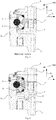
- FIG. 1 is a schematic partial sectional view of a roller bearing 100 according to the prior art.
- the roller bearing 100 has the first ring 1 and the second ring 2, which are arranged concentrically and are rotatably connected to one another with a two-row roller bearing with the roller bodies 3.
- the first ring 1 is a split ring. It has the first partial ring 1 'and the second partial ring 1 ′′, which are screwed together in the bore 8. This enables simple assembly of the roller bearing 100.
- the second ring 2 has the means 7 for driving the roller bearing 100 Operating loads in the axial direction A, the form fit in the raceway system prevents the first ring 1 and the second ring 2 from being separated in the axial direction A.
- the first ring 1 may move in the radial direction R. deformed so that the form fit in the raceway system is no longer given. Consequently, the first ring 1 and the second ring 2 separate under the action of the load in the axial direction A.
- FIG. 2 is a schematic partial sectional view of a rolling bearing 100 according to an exemplary embodiment of the present invention.
- the roller bearing 100 like that in FIG Figure 1
- the rolling bearing 100 shown has the split first ring 1 with the first partial ring 1 'and the second partial ring 1 "and the second ring 2.
- the first ring 1 and the second ring 2 are rotatably connected to one another by rolling elements 3 rolling between them
- Ring 2 has the means 7 for driving the roller bearing 100.
- the first partial ring 1 ′ and the second partial ring 1 ′′ are screwed together in the bore 8.
- the roller bearing 100 shown has the first ring 1, the nose 4, which engages in the groove 5 of the second ring 2.
- the nose 4 is spaced from the surface of the second ring 2 in the area of the groove 5, so that there is no friction between the first ring 1 and the second ring 2 when the roller bearing 100 is in operation.
- the roller bearing 100 shown is an angular roller bearing which is designed as a wire roller bearing.
- the nose 4 has a wall thickness that is greater than 50% of the diameter of the rolling elements 3 of the rolling bearing 100. In the case of the rolling bearing 100 shown, both rows of rolling elements have the same diameter, which are thus both rolling elements with the largest diameter in the sense of this application are valid.
- the form fit in the raceway system prevents the first ring 1 and the second ring 2 from being separated in the axial direction A.
- the first ring 1 deforms in the radial direction R. This deformation is, however, limited by a form fit between the nose 4 and the groove 5, which in turn maintains the form fit in the track system in the axial direction A and thus prevents it that the first ring 1 and the second ring 2 are separated.
- FIG. 3 A schematic diagram of an apparatus 200 in accordance with an exemplary embodiment of the present invention is shown.
- the device 200 has the rotatable upper part 201 and the lower part 202.
- the upper part 201 and the lower part are connected to the roller bearing 100 according to the invention.
Landscapes
- Engineering & Computer Science (AREA)
- General Engineering & Computer Science (AREA)
- Mechanical Engineering (AREA)
- Rolling Contact Bearings (AREA)
Claims (10)
- Palier à roulement (100) comprenant une première bague (1) et une deuxième bague (2) agencée concentriquement à la première bague (1), la première bague (1) étant une bague intérieure du palier à roulement (100) et la deuxième bague (2) étant une bague extérieure du palier à roulement (100) ou la première bague (1) étant une bague extérieure du palier à roulement (100) et la deuxième bague (2) étant une bague intérieure du palier à roulement (100), le palier à roulement (100) étant une liaison de rotation à plusieurs rangées, dans laquelle une séparation de la bague intérieure et de la bague extérieure dans la direction axiale (A) est limitée par un accouplement de forme dans le système de piste de déplacement et le palier à roulement (100) est un palier à rouleaux oblique ou à billes oblique, dans lequel la première bague (1) et la deuxième bague (2) sont reliées de manière rotative l'une par rapport à l'autre autour d'un axe de rotation agencé dans la direction axiale (A), la première bague (1) comprenant un bec (4) pénétrant dans la direction axiale (A) dans une rainure (5), concentrique autour de l'axe de rotation, de la deuxième bague (2), caractérisé en ce que le bec (4) est espacé de la rainure (5) de telle sorte qu'une fente entourant le bec (4) soit formée dans un mode d'exploitation normal entre le bec (4) et la rainure (5), et le bec (4) présente une épaisseur de paroi qui est supérieure à 50 % du diamètre des corps de roulement du palier à roulement (100) ayant le plus grand diamètre, et, en cas de sollicitations extrêmes dans la direction axiale (A) avec déformation de la première bague (1) dans la direction radiale (R), un accouplement de forme du bec (4) avec la rainure (5) se met en place, qui limite la déformation et maintient l'accouplement de forme dans le système de piste de déplacement dans la direction axiale (A).
- Palier à roulement (100) selon la revendication 1, dans lequel le bec (4) est concentrique autour de l'axe de rotation.
- Palier à roulement (100) selon l'une quelconque des revendications précédentes, dans lequel la première bague (1) comprend au moins une première bague partielle (1') et une deuxième bague partielle (1").
- Palier à roulement (100) selon l'une quelconque des revendications précédentes, dans lequel le palier à roulement (100) est une liaison de rotation à rouleaux à plusieurs rangées.
- Palier à roulement (100) selon la revendication 4, dans lequel le bec (4) est formé d'un seul tenant avec la première bague partielle (1'), la première bague partielle (1') dépassant une rangée de rouleaux du palier à roulement (100) dans la direction axiale (A).
- Palier à roulement (100) selon l'une quelconque des revendications précédentes, dans lequel la deuxième bague (2) comprend un moyen (7) pour l'entraînement du palier à roulement (100), le moyen (7) étant de préférence une rangée de dents.
- Palier à roulement (100) selon l'une quelconque des revendications précédentes, dans lequel une fente est agencée entre le bec (4) et la surface de la deuxième bague (2) dans la zone de la rainure (5), un joint d'étanchéité étant agencé au niveau de la première bague (1) et/ou au niveau de la deuxième bague (2) pour l'étanchéification de la fente, le joint d'étanchéité étant de préférence une lèvre en caoutchouc circonférentielle.
- Palier à roulement (100) selon l'une quelconque des revendications précédentes, dans lequel le palier à roulement (100) est un palier à roulement à fils.
- Procédé d'exploitation d'un palier à roulement (100) selon l'une quelconque des revendications précédentes,
dans lequel des déformations de la première bague (1) dans une direction radiale (R) orthogonale à la direction axiale (A) sont provoquées par un mouvement de la première bague (1) dans la direction axiale (A) par rapport à la deuxième bague (2),
dans lequel les déformations de la première bague (1) dans la direction radiale (R) sont limitées par un accouplement de forme du bec (4) avec la rainure (5), dans lequel le mouvement de la première bague (1) dans la direction axiale (A) est limité par la limitation des déformations de la première bague (1) dans la direction radiale (R). - Dispositif (200) comprenant un palier à roulement (100) selon l'une quelconque des revendications 1 à 8.
Applications Claiming Priority (1)
| Application Number | Priority Date | Filing Date | Title |
|---|---|---|---|
| DE102018222789.6A DE102018222789A1 (de) | 2018-12-21 | 2018-12-21 | Wälzlager mit radialem Fangring zur Begrenzung von radialen Verformungen des Wälzlagers |
Publications (2)
| Publication Number | Publication Date |
|---|---|
| EP3670948A1 EP3670948A1 (fr) | 2020-06-24 |
| EP3670948B1 true EP3670948B1 (fr) | 2021-08-04 |
Family
ID=68965664
Family Applications (1)
| Application Number | Title | Priority Date | Filing Date |
|---|---|---|---|
| EP19217624.6A Active EP3670948B1 (fr) | 2018-12-21 | 2019-12-18 | Palier à roulement pourvu de bague d'arrêt radiale permettant de limiter la déformation radiale du palier à roulement |
Country Status (2)
| Country | Link |
|---|---|
| EP (1) | EP3670948B1 (fr) |
| DE (1) | DE102018222789A1 (fr) |
Citations (1)
| Publication number | Priority date | Publication date | Assignee | Title |
|---|---|---|---|---|
| DD17558A1 (de) * | 1957-08-21 | 1959-10-13 | Drehkranz für Krane, Bagger und sonstige Rotations- und Schwenkgeräte |
Family Cites Families (7)
| Publication number | Priority date | Publication date | Assignee | Title |
|---|---|---|---|---|
| US2488825A (en) * | 1945-10-22 | 1949-11-22 | Palumbo Vincent | Antifriction bearing |
| DE1818279U (de) * | 1959-02-11 | 1960-09-15 | Rudolf Lensing | Lagerelement fuer langsamlaufende drehverbindungen. |
| JPH07109646A (ja) * | 1993-10-12 | 1995-04-25 | Fukuhara Seiki Seisakusho:Kk | 丸編機のシリンダー基筒部におけるベアリング装置 |
| JP2000192357A (ja) * | 1998-12-21 | 2000-07-11 | Precision Fukuhara Works Ltd | 丸編機における油漏れ防止装置 |
| DE102008035003A1 (de) * | 2008-07-25 | 2010-02-04 | Rothe Erde Gmbh | Rollenlager, insbesondere mittenfreies Großwälzlager |
| DE102013100679A1 (de) * | 2013-01-23 | 2014-07-24 | Thyssenkrupp Rothe Erde Gmbh | Zylinderrollenlager |
| DE102014104863B4 (de) * | 2014-04-04 | 2018-02-22 | Thyssenkrupp Ag | Wälzlageranordnung und Windkraftanlage |
-
2018
- 2018-12-21 DE DE102018222789.6A patent/DE102018222789A1/de not_active Ceased
-
2019
- 2019-12-18 EP EP19217624.6A patent/EP3670948B1/fr active Active
Patent Citations (1)
| Publication number | Priority date | Publication date | Assignee | Title |
|---|---|---|---|---|
| DD17558A1 (de) * | 1957-08-21 | 1959-10-13 | Drehkranz für Krane, Bagger und sonstige Rotations- und Schwenkgeräte |
Also Published As
| Publication number | Publication date |
|---|---|
| DE102018222789A1 (de) | 2020-06-25 |
| EP3670948A1 (fr) | 2020-06-24 |
Similar Documents
| Publication | Publication Date | Title |
|---|---|---|
| EP2035718B1 (fr) | Roulement à contact oblique à deux rangées comprenant une bague extérieure de roulement en deux parties et une bague intérieure de roulement à une rangée | |
| EP2024653B1 (fr) | Palier à roulement avec deux bagues internes et un agencement d'étanchéité pour l'étanchéité du joint de séparation entre les bagues internes | |
| EP2715162B2 (fr) | Couronne d'orientation | |
| EP2640990B1 (fr) | Ensemble palier à palier de sécurité | |
| WO2019201662A1 (fr) | Palier à roulement de grande dimension | |
| EP1972802B1 (fr) | Roulement à rouleaux oblique | |
| DE102014106587B4 (de) | Wälzlager, insbesondere Vierpunktlager oder Doppelvierpunktlager für Windkraftanlagen | |
| EP1837536A2 (fr) | Roulement à rouleaux à contact oblique | |
| DE102016214350A1 (de) | Verfahren und Vorrichtung zur Herstellung eines Schrägrollenlagers | |
| EP3109493A1 (fr) | Agencement de palier a roulement et logement de pale pour une eolienne | |
| DE102014205912A1 (de) | Montagesystem für einreihige Wälzlager | |
| DE102014219702A1 (de) | Laufbahnstruktur für ein Wälzlager und Verfahren | |
| DE102014210155A1 (de) | Pendelrollenlager und Verfahren zur Montage eines Pendelrollenlagers | |
| DE10311851B4 (de) | Schwenklagerung | |
| EP3670948A1 (fr) | Palier à roulement pourvu de bague d'arrêt radiale permettant de limiter la déformation radiale du palier à roulement | |
| DE102013225331B4 (de) | Lageranordnung mit Labyrinthdichtung | |
| DE102022213073A1 (de) | Wälzlager mit auskragender Nase und Getriebe | |
| EP2944836B1 (fr) | Palier à roulement | |
| DE102018105242B3 (de) | Radial-schrägrollenlager | |
| DE102021208077B4 (de) | Sicherungsring zur axialen Sicherung eines Wälzlagers, Lageranordnung mit dem Sicherungsring sowie Verfahren zur Montage des Sicherungsrings | |
| DE102020131335B4 (de) | Wälzlager | |
| EP1995476B1 (fr) | Roulement à fils | |
| DE102015118599A1 (de) | Lageranordnung | |
| EP2644920A2 (fr) | Roulement avec joint d'étanchéité bloqué dans une gorge prevue sur la face d'une bague de roulement | |
| DE102014205812A1 (de) | Wälzlager |
Legal Events
| Date | Code | Title | Description |
|---|---|---|---|
| PUAI | Public reference made under article 153(3) epc to a published international application that has entered the european phase |
Free format text: ORIGINAL CODE: 0009012 |
|
| STAA | Information on the status of an ep patent application or granted ep patent |
Free format text: STATUS: THE APPLICATION HAS BEEN PUBLISHED |
|
| AK | Designated contracting states |
Kind code of ref document: A1 Designated state(s): AL AT BE BG CH CY CZ DE DK EE ES FI FR GB GR HR HU IE IS IT LI LT LU LV MC MK MT NL NO PL PT RO RS SE SI SK SM TR |
|
| AX | Request for extension of the european patent |
Extension state: BA ME |
|
| STAA | Information on the status of an ep patent application or granted ep patent |
Free format text: STATUS: REQUEST FOR EXAMINATION WAS MADE |
|
| 17P | Request for examination filed |
Effective date: 20210111 |
|
| RBV | Designated contracting states (corrected) |
Designated state(s): AL AT BE BG CH CY CZ DE DK EE ES FI FR GB GR HR HU IE IS IT LI LT LU LV MC MK MT NL NO PL PT RO RS SE SI SK SM TR |
|
| RAP1 | Party data changed (applicant data changed or rights of an application transferred) |
Owner name: THYSSENKRUPP ROTHE ERDE GERMANY GMBH Owner name: THYSSENKRUPP AG |
|
| GRAP | Despatch of communication of intention to grant a patent |
Free format text: ORIGINAL CODE: EPIDOSNIGR1 |
|
| STAA | Information on the status of an ep patent application or granted ep patent |
Free format text: STATUS: GRANT OF PATENT IS INTENDED |
|
| INTG | Intention to grant announced |
Effective date: 20210407 |
|
| GRAS | Grant fee paid |
Free format text: ORIGINAL CODE: EPIDOSNIGR3 |
|
| GRAA | (expected) grant |
Free format text: ORIGINAL CODE: 0009210 |
|
| STAA | Information on the status of an ep patent application or granted ep patent |
Free format text: STATUS: THE PATENT HAS BEEN GRANTED |
|
| AK | Designated contracting states |
Kind code of ref document: B1 Designated state(s): AL AT BE BG CH CY CZ DE DK EE ES FI FR GB GR HR HU IE IS IT LI LT LU LV MC MK MT NL NO PL PT RO RS SE SI SK SM TR |
|
| REG | Reference to a national code |
Ref country code: GB Ref legal event code: FG4D Free format text: NOT ENGLISH |
|
| REG | Reference to a national code |
Ref country code: AT Ref legal event code: REF Ref document number: 1417269 Country of ref document: AT Kind code of ref document: T Effective date: 20210815 |
|
| REG | Reference to a national code |
Ref country code: CH Ref legal event code: EP |
|
| REG | Reference to a national code |
Ref country code: DE Ref legal event code: R096 Ref document number: 502019001963 Country of ref document: DE |
|
| REG | Reference to a national code |
Ref country code: IE Ref legal event code: FG4D Free format text: LANGUAGE OF EP DOCUMENT: GERMAN |
|
| REG | Reference to a national code |
Ref country code: LT Ref legal event code: MG9D |
|
| REG | Reference to a national code |
Ref country code: NL Ref legal event code: MP Effective date: 20210804 |
|
| PG25 | Lapsed in a contracting state [announced via postgrant information from national office to epo] |
Ref country code: ES Free format text: LAPSE BECAUSE OF FAILURE TO SUBMIT A TRANSLATION OF THE DESCRIPTION OR TO PAY THE FEE WITHIN THE PRESCRIBED TIME-LIMIT Effective date: 20210804 Ref country code: SE Free format text: LAPSE BECAUSE OF FAILURE TO SUBMIT A TRANSLATION OF THE DESCRIPTION OR TO PAY THE FEE WITHIN THE PRESCRIBED TIME-LIMIT Effective date: 20210804 Ref country code: RS Free format text: LAPSE BECAUSE OF FAILURE TO SUBMIT A TRANSLATION OF THE DESCRIPTION OR TO PAY THE FEE WITHIN THE PRESCRIBED TIME-LIMIT Effective date: 20210804 Ref country code: BG Free format text: LAPSE BECAUSE OF FAILURE TO SUBMIT A TRANSLATION OF THE DESCRIPTION OR TO PAY THE FEE WITHIN THE PRESCRIBED TIME-LIMIT Effective date: 20211104 Ref country code: LT Free format text: LAPSE BECAUSE OF FAILURE TO SUBMIT A TRANSLATION OF THE DESCRIPTION OR TO PAY THE FEE WITHIN THE PRESCRIBED TIME-LIMIT Effective date: 20210804 Ref country code: FI Free format text: LAPSE BECAUSE OF FAILURE TO SUBMIT A TRANSLATION OF THE DESCRIPTION OR TO PAY THE FEE WITHIN THE PRESCRIBED TIME-LIMIT Effective date: 20210804 Ref country code: HR Free format text: LAPSE BECAUSE OF FAILURE TO SUBMIT A TRANSLATION OF THE DESCRIPTION OR TO PAY THE FEE WITHIN THE PRESCRIBED TIME-LIMIT Effective date: 20210804 Ref country code: NO Free format text: LAPSE BECAUSE OF FAILURE TO SUBMIT A TRANSLATION OF THE DESCRIPTION OR TO PAY THE FEE WITHIN THE PRESCRIBED TIME-LIMIT Effective date: 20211104 Ref country code: PT Free format text: LAPSE BECAUSE OF FAILURE TO SUBMIT A TRANSLATION OF THE DESCRIPTION OR TO PAY THE FEE WITHIN THE PRESCRIBED TIME-LIMIT Effective date: 20211206 |
|
| PG25 | Lapsed in a contracting state [announced via postgrant information from national office to epo] |
Ref country code: PL Free format text: LAPSE BECAUSE OF FAILURE TO SUBMIT A TRANSLATION OF THE DESCRIPTION OR TO PAY THE FEE WITHIN THE PRESCRIBED TIME-LIMIT Effective date: 20210804 Ref country code: LV Free format text: LAPSE BECAUSE OF FAILURE TO SUBMIT A TRANSLATION OF THE DESCRIPTION OR TO PAY THE FEE WITHIN THE PRESCRIBED TIME-LIMIT Effective date: 20210804 Ref country code: GR Free format text: LAPSE BECAUSE OF FAILURE TO SUBMIT A TRANSLATION OF THE DESCRIPTION OR TO PAY THE FEE WITHIN THE PRESCRIBED TIME-LIMIT Effective date: 20211105 |
|
| PG25 | Lapsed in a contracting state [announced via postgrant information from national office to epo] |
Ref country code: NL Free format text: LAPSE BECAUSE OF FAILURE TO SUBMIT A TRANSLATION OF THE DESCRIPTION OR TO PAY THE FEE WITHIN THE PRESCRIBED TIME-LIMIT Effective date: 20210804 |
|
| PG25 | Lapsed in a contracting state [announced via postgrant information from national office to epo] |
Ref country code: DK Free format text: LAPSE BECAUSE OF FAILURE TO SUBMIT A TRANSLATION OF THE DESCRIPTION OR TO PAY THE FEE WITHIN THE PRESCRIBED TIME-LIMIT Effective date: 20210804 |
|
| REG | Reference to a national code |
Ref country code: DE Ref legal event code: R097 Ref document number: 502019001963 Country of ref document: DE |
|
| PG25 | Lapsed in a contracting state [announced via postgrant information from national office to epo] |
Ref country code: SM Free format text: LAPSE BECAUSE OF FAILURE TO SUBMIT A TRANSLATION OF THE DESCRIPTION OR TO PAY THE FEE WITHIN THE PRESCRIBED TIME-LIMIT Effective date: 20210804 Ref country code: SK Free format text: LAPSE BECAUSE OF FAILURE TO SUBMIT A TRANSLATION OF THE DESCRIPTION OR TO PAY THE FEE WITHIN THE PRESCRIBED TIME-LIMIT Effective date: 20210804 Ref country code: RO Free format text: LAPSE BECAUSE OF FAILURE TO SUBMIT A TRANSLATION OF THE DESCRIPTION OR TO PAY THE FEE WITHIN THE PRESCRIBED TIME-LIMIT Effective date: 20210804 Ref country code: EE Free format text: LAPSE BECAUSE OF FAILURE TO SUBMIT A TRANSLATION OF THE DESCRIPTION OR TO PAY THE FEE WITHIN THE PRESCRIBED TIME-LIMIT Effective date: 20210804 Ref country code: CZ Free format text: LAPSE BECAUSE OF FAILURE TO SUBMIT A TRANSLATION OF THE DESCRIPTION OR TO PAY THE FEE WITHIN THE PRESCRIBED TIME-LIMIT Effective date: 20210804 Ref country code: AL Free format text: LAPSE BECAUSE OF FAILURE TO SUBMIT A TRANSLATION OF THE DESCRIPTION OR TO PAY THE FEE WITHIN THE PRESCRIBED TIME-LIMIT Effective date: 20210804 |
|
| PLBE | No opposition filed within time limit |
Free format text: ORIGINAL CODE: 0009261 |
|
| STAA | Information on the status of an ep patent application or granted ep patent |
Free format text: STATUS: NO OPPOSITION FILED WITHIN TIME LIMIT |
|
| 26N | No opposition filed |
Effective date: 20220506 |
|
| PG25 | Lapsed in a contracting state [announced via postgrant information from national office to epo] |
Ref country code: MC Free format text: LAPSE BECAUSE OF FAILURE TO SUBMIT A TRANSLATION OF THE DESCRIPTION OR TO PAY THE FEE WITHIN THE PRESCRIBED TIME-LIMIT Effective date: 20210804 Ref country code: IT Free format text: LAPSE BECAUSE OF FAILURE TO SUBMIT A TRANSLATION OF THE DESCRIPTION OR TO PAY THE FEE WITHIN THE PRESCRIBED TIME-LIMIT Effective date: 20210804 |
|
| PG25 | Lapsed in a contracting state [announced via postgrant information from national office to epo] |
Ref country code: SI Free format text: LAPSE BECAUSE OF FAILURE TO SUBMIT A TRANSLATION OF THE DESCRIPTION OR TO PAY THE FEE WITHIN THE PRESCRIBED TIME-LIMIT Effective date: 20210804 |
|
| REG | Reference to a national code |
Ref country code: BE Ref legal event code: MM Effective date: 20211231 |
|
| PG25 | Lapsed in a contracting state [announced via postgrant information from national office to epo] |
Ref country code: LU Free format text: LAPSE BECAUSE OF NON-PAYMENT OF DUE FEES Effective date: 20211218 Ref country code: IE Free format text: LAPSE BECAUSE OF NON-PAYMENT OF DUE FEES Effective date: 20211218 |
|
| PG25 | Lapsed in a contracting state [announced via postgrant information from national office to epo] |
Ref country code: FR Free format text: LAPSE BECAUSE OF NON-PAYMENT OF DUE FEES Effective date: 20211231 Ref country code: BE Free format text: LAPSE BECAUSE OF NON-PAYMENT OF DUE FEES Effective date: 20211231 |
|
| PG25 | Lapsed in a contracting state [announced via postgrant information from national office to epo] |
Ref country code: CY Free format text: LAPSE BECAUSE OF FAILURE TO SUBMIT A TRANSLATION OF THE DESCRIPTION OR TO PAY THE FEE WITHIN THE PRESCRIBED TIME-LIMIT Effective date: 20210804 |
|
| PG25 | Lapsed in a contracting state [announced via postgrant information from national office to epo] |
Ref country code: HU Free format text: LAPSE BECAUSE OF FAILURE TO SUBMIT A TRANSLATION OF THE DESCRIPTION OR TO PAY THE FEE WITHIN THE PRESCRIBED TIME-LIMIT; INVALID AB INITIO Effective date: 20191218 |
|
| REG | Reference to a national code |
Ref country code: CH Ref legal event code: PL |
|
| PG25 | Lapsed in a contracting state [announced via postgrant information from national office to epo] |
Ref country code: LI Free format text: LAPSE BECAUSE OF NON-PAYMENT OF DUE FEES Effective date: 20221231 Ref country code: CH Free format text: LAPSE BECAUSE OF NON-PAYMENT OF DUE FEES Effective date: 20221231 |
|
| PG25 | Lapsed in a contracting state [announced via postgrant information from national office to epo] |
Ref country code: MK Free format text: LAPSE BECAUSE OF FAILURE TO SUBMIT A TRANSLATION OF THE DESCRIPTION OR TO PAY THE FEE WITHIN THE PRESCRIBED TIME-LIMIT Effective date: 20210804 |
|
| PG25 | Lapsed in a contracting state [announced via postgrant information from national office to epo] |
Ref country code: TR Free format text: LAPSE BECAUSE OF FAILURE TO SUBMIT A TRANSLATION OF THE DESCRIPTION OR TO PAY THE FEE WITHIN THE PRESCRIBED TIME-LIMIT Effective date: 20210804 |
|
| GBPC | Gb: european patent ceased through non-payment of renewal fee |
Effective date: 20231218 |
|
| PG25 | Lapsed in a contracting state [announced via postgrant information from national office to epo] |
Ref country code: MT Free format text: LAPSE BECAUSE OF FAILURE TO SUBMIT A TRANSLATION OF THE DESCRIPTION OR TO PAY THE FEE WITHIN THE PRESCRIBED TIME-LIMIT Effective date: 20210804 |
|
| PG25 | Lapsed in a contracting state [announced via postgrant information from national office to epo] |
Ref country code: GB Free format text: LAPSE BECAUSE OF NON-PAYMENT OF DUE FEES Effective date: 20231218 |
|
| PG25 | Lapsed in a contracting state [announced via postgrant information from national office to epo] |
Ref country code: GB Free format text: LAPSE BECAUSE OF NON-PAYMENT OF DUE FEES Effective date: 20231218 |
|
| PGFP | Annual fee paid to national office [announced via postgrant information from national office to epo] |
Ref country code: DE Payment date: 20251211 Year of fee payment: 7 |
|
| REG | Reference to a national code |
Ref country code: AT Ref legal event code: MM01 Ref document number: 1417269 Country of ref document: AT Kind code of ref document: T Effective date: 20241218 |
|
| PG25 | Lapsed in a contracting state [announced via postgrant information from national office to epo] |
Ref country code: AT Free format text: LAPSE BECAUSE OF NON-PAYMENT OF DUE FEES Effective date: 20241218 |
|
| PGFP | Annual fee paid to national office [announced via postgrant information from national office to epo] |
Ref country code: AT Payment date: 20260410 Year of fee payment: 5 |