EP3670985A1 - Système de rétention, système - Google Patents
Système de rétention, système Download PDFInfo
- Publication number
- EP3670985A1 EP3670985A1 EP18213241.5A EP18213241A EP3670985A1 EP 3670985 A1 EP3670985 A1 EP 3670985A1 EP 18213241 A EP18213241 A EP 18213241A EP 3670985 A1 EP3670985 A1 EP 3670985A1
- Authority
- EP
- European Patent Office
- Prior art keywords
- retainer
- base
- recess
- component
- projection
- Prior art date
- Legal status (The legal status is an assumption and is not a legal conclusion. Google has not performed a legal analysis and makes no representation as to the accuracy of the status listed.)
- Withdrawn
Links
Images

Classifications
-
- F—MECHANICAL ENGINEERING; LIGHTING; HEATING; WEAPONS; BLASTING
- F16—ENGINEERING ELEMENTS AND UNITS; GENERAL MEASURES FOR PRODUCING AND MAINTAINING EFFECTIVE FUNCTIONING OF MACHINES OR INSTALLATIONS; THERMAL INSULATION IN GENERAL
- F16B—DEVICES FOR FASTENING OR SECURING CONSTRUCTIONAL ELEMENTS OR MACHINE PARTS TOGETHER, e.g. NAILS, BOLTS, CIRCLIPS, CLAMPS, CLIPS OR WEDGES; JOINTS OR JOINTING
- F16B2/00—Friction-grip releasable fastenings
- F16B2/02—Clamps, i.e. with gripping action effected by positive means other than the inherent resistance to deformation of the material of the fastening
- F16B2/06—Clamps, i.e. with gripping action effected by positive means other than the inherent resistance to deformation of the material of the fastening external, i.e. with contracting action
- F16B2/10—Clamps, i.e. with gripping action effected by positive means other than the inherent resistance to deformation of the material of the fastening external, i.e. with contracting action using pivoting jaws
-
- B—PERFORMING OPERATIONS; TRANSPORTING
- B60—VEHICLES IN GENERAL
- B60R—VEHICLES, VEHICLE FITTINGS, OR VEHICLE PARTS, NOT OTHERWISE PROVIDED FOR
- B60R16/00—Electric or fluid circuits specially adapted for vehicles and not otherwise provided for; Arrangement of elements of electric or fluid circuits specially adapted for vehicles and not otherwise provided for
- B60R16/02—Electric or fluid circuits specially adapted for vehicles and not otherwise provided for; Arrangement of elements of electric or fluid circuits specially adapted for vehicles and not otherwise provided for electric constitutive elements
- B60R16/0207—Wire harnesses
- B60R16/0215—Protecting, fastening and routing means therefor
-
- F—MECHANICAL ENGINEERING; LIGHTING; HEATING; WEAPONS; BLASTING
- F16—ENGINEERING ELEMENTS AND UNITS; GENERAL MEASURES FOR PRODUCING AND MAINTAINING EFFECTIVE FUNCTIONING OF MACHINES OR INSTALLATIONS; THERMAL INSULATION IN GENERAL
- F16B—DEVICES FOR FASTENING OR SECURING CONSTRUCTIONAL ELEMENTS OR MACHINE PARTS TOGETHER, e.g. NAILS, BOLTS, CIRCLIPS, CLAMPS, CLIPS OR WEDGES; JOINTS OR JOINTING
- F16B2/00—Friction-grip releasable fastenings
- F16B2/02—Clamps, i.e. with gripping action effected by positive means other than the inherent resistance to deformation of the material of the fastening
- F16B2/14—Clamps, i.e. with gripping action effected by positive means other than the inherent resistance to deformation of the material of the fastening using wedges
-
- F—MECHANICAL ENGINEERING; LIGHTING; HEATING; WEAPONS; BLASTING
- F16—ENGINEERING ELEMENTS AND UNITS; GENERAL MEASURES FOR PRODUCING AND MAINTAINING EFFECTIVE FUNCTIONING OF MACHINES OR INSTALLATIONS; THERMAL INSULATION IN GENERAL
- F16L—PIPES; JOINTS OR FITTINGS FOR PIPES; SUPPORTS FOR PIPES, CABLES OR PROTECTIVE TUBING; MEANS FOR THERMAL INSULATION IN GENERAL
- F16L3/00—Supports for pipes, cables or protective tubing, e.g. hangers, holders, clamps, cleats, clips, brackets
- F16L3/08—Supports for pipes, cables or protective tubing, e.g. hangers, holders, clamps, cleats, clips, brackets substantially surrounding the pipe, cable or protective tubing
- F16L3/10—Supports for pipes, cables or protective tubing, e.g. hangers, holders, clamps, cleats, clips, brackets substantially surrounding the pipe, cable or protective tubing divided, i.e. with two members engaging the pipe, cable or protective tubing
- F16L3/1075—Supports for pipes, cables or protective tubing, e.g. hangers, holders, clamps, cleats, clips, brackets substantially surrounding the pipe, cable or protective tubing divided, i.e. with two members engaging the pipe, cable or protective tubing with two members, the two members being joined with a hinge on one side and fastened together on the other side
Definitions
- the present invention relates to a retainer, in particular a self-locking retainer, the retainer comprising a base and a cover that can be moved relative to the base between an open position and a locked position, with a reception space for components being formed between the base and the cover in the locked position.
- the invention further relates to a system comprising a retainer and a component.
- retainers are used. Moreover, to ensure that the position of the component relative to the further component does not change over time, comparatively high assembly forces typically only achievable through the use of tools are exerted on the retainer during the assembly of the retainer.
- Such a retainer in particular a self-locking retainer, comprises a base and a cover that can be moved relative to the base between an open position and a locked position, with a reception space for components being formed between the base and the cover in the locked position, wherein the base comprises a recess at an inner sidewall of the base and the cover comprises a projection that is received in the recess in the locked position, wherein part of the projection forms part of the reception space in the locked position and wherein the projection is configured to be moveable in the recess in the locked position.
- a retainer is formed by means of which a linear movement of the component stored in the retainer can be counteracted by an increase in the interference experienced between the projection that is moveable in the recess and the recess in the locked position. This means that if the component wants to move in one direction the movement of the projection in the retainer is able to counteract this movement so that the component maintains its position in the retainer.
- the use of the retainers can be more environmentally friendly than cable ties or the use of double sided tape.
- the projection may be of two-part design with a material of the first part being softer than a material of the second part, preferably with the first part being configured to directly contact the component when the component is arranged within the retainer.
- the first part may be configured to contact the component in the locked position and the second part is configured to contact the recess in the locked position.
- the second part may be configured to be moveable relative to the sidewall in the recess in the locked position.
- the second part may have a back wall that is configured to contact said recess and that is shaped complementary to said sidewall.
- the projection may have one or more planar surfaces that project into the reception space in the locked position.
- planar surfaces are also comparatively simple to manufacture.
- the base may comprise two openings at opposing sides, preferably wherein the openings may have a U-shaped or V-shaped cross-section. In this way a component can be guided through the retainer in a simple manner. Moreover, U-shaped as well as V-shaped openings can be produced in a comparatively simple manner.
- the recess may extend from a top side to a bottom side of the base. In this way a complete side of the retainer can be formed to be able to interact with the projection in order to enhance the contact area and contact force between the projection and the component stored within the retainer.
- a valley of the recess may be inclined with respect to the bottom side of the base.
- By forming the recess such that it is inclined with respect to the bottom side of the base further facilitates the interaction between the base and the coved, more specifically between the projection and the recess.
- the recess may have one of a U-shaped or V-shaped shape at least in a cross-section in a plane extending in parallel to the bottom side. Such shapes aid in increasing the contact force between the retainer and the component and hence in maintaining the predefined position of the component within the retainer. Moreover, U-shaped as well as V-shaped openings can be produced in a comparatively simple manner.
- One or more lugs may be provided at a side of the base disposed opposite to the recess, with the lugs projecting into the reception space, preferably with the lugs being able to be arranged at the top side.
- the lugs aid in avoiding the component from exiting the retainer on closing the cover relative to the base as they can prevent the component from escaping upwardly.
- the lugs also aid in increasing a contact force between the component and the retainer to maintain the predefined position of the component within the retainer for a longer period of time than was previously possible.
- At least one of the cover and the base may be configured to be coupled to a further component, preferably wherein at least one of the base and the cover may comprise a connector portion at an outer side thereof.
- the cover may be pivotable about a pivot axis relative to the base between the open position and the locked position, preferably wherein one of the cover and the base may comprise an axle that may be received in one or more sleeves arranged at the other one of the cover and the base.
- one of the cover and the base may comprise an axle that may be received in one or more sleeves arranged at the other one of the cover and the base.
- the cover may be locked at the base by means of a snap fit connection, with one of the base and the cover being able to comprise a nose cooperating with a recess provided at the other one of the base and the cover.
- a snap fit connection is a secure and easy to form type of connection.
- the present invention relates to a system comprising a retainer and a component received in the reception space of the retainer, wherein the component is e.g. one of a wire, a cable, a cable harness, a duct, a hose, and a pipe, wherein the component is retained in a self-locking manner in the reception space by means of an interaction between the component, the recess and the projection.
- the component is e.g. one of a wire, a cable, a cable harness, a duct, a hose, and a pipe, wherein the component is retained in a self-locking manner in the reception space by means of an interaction between the component, the recess and the projection.
- a friction between the projection and the component may be greater than the friction between the projection and the base. In this way one can enhance the interaction between the projection, the recess and the component to be stored in the retainer to ensure the component maintains its position within the retainer over time.
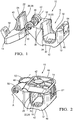
- Fig. 1 shows a perspective schematic view of a retainer 10 in an open position, i.e. a state in which the retainer 10 is delivered to a customer.
- the retainer 10 comprises a base 12 and a cover 14 that can be moved relative to the base 12 between the open position and a locked position, i.e. an assembly state of the retainer 10.
- a reception space 16 for components 100 is formed between the base 12 and the cover 14 in the locked position.
- the cover 14 is pivotable about a pivot axis A relative to the base 12 between the open position and the locked position.
- the cover 14 comprises an axle 48 that is received in two sleeves 50 arranged at the base 12.
- the base 12 comprises a recess 18 at an inner sidewall 20 of the base 12 and the cover 14 comprises a projection 22 that is received in the recess 18 in the locked position (see e.g. Fig. 2 ), with part of the projection 22 forming part of the reception space 16 in the locked position.
- the projection 22 is configured to be moveable in the recess 18 in the locked position.
- the projection 22 is of two-part design with a material of the first part 24 being softer than a material of the second part 26. By forming the material of the first part 24 softer than the material of the second part 26 one can facilitate that the friction ⁇ s between the projection 22 and the component 100 to be stored in the retainer 10 is greater than the friction ⁇ H between the projection 22 and the base 12.
- the first part 24, i.e. the softer part, is configured to contact the component 100 in the locked position and the second part 26, i.e. the harder part, is configured to contact the recess 18 in the locked position.
- the recess 18 extends from a top side 32 to a bottom side 34 of the base 12.
- a valley 36 of the recess 18 is inclined with respect to the bottom side 34 of the base 12.
- An angle of inclination of the valley 36 is typically selected in the range of 95° to 125° and in the present embodiment amounts to 105°.
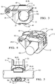
- the base 12 comprises two openings 30 at opposing sides, with the openings 30 having a U-shaped shape in the embodiment shown. It should be noted that the openings 30 could also have a V-shaped shape. As indicated in Fig. 3 , the component 100, such as a pipe is guided through each of the openings 30.
- Both the cover 14 and the base 12 of the retainer 10 comprise a respective connector portion 42 via which the retainer can be coupled to a further component, such as the chassis of a vehicle (not shown).
- a further component such as the chassis of a vehicle (not shown).
- the connector portion 42 provided at the base is arranged at an outer side 46 of the base 12.
- the connector portion 42 provided at the cover 14 is arranged at an outer side 44 of the cover 14.
- connector portion 42 may be provided at the retainer 10 and that the position of the connector portion(s) 42 may vary in comparison to the ones shown in the Figures.
- the cover 14 can be locked to the base 12 by means of a snap fit connection 52 (see Fig. 2 showing the assembled snap fit connection 52).
- the base 12 comprises a nose 54 cooperating with a recess 56 provided at the cover 14.
- Fig. 2 shows a perspective schematic view of the retainer 10 of Fig. 1 in a locked position.
- the second part 26 of the projection 22, like the projection 22 is configured to be moveable relative to the sidewall 20 in the recess 18 in the locked position. The reason for this will be explained in the following.
- the projection 22 has two planar surfaces 40 arranged at the first part 24 disposed opposite to the second part.
- the planar surfaces 40 project into the reception space 16 in the locked position.
- the component 100 to be stored in the reception space 16 can be clamped into position by means of the interaction of the planar surfaces 40 and the base 12.
- Fig. 3 shows a perspective schematic side view of the retainer 10 in the locked position with the component 100 arranged therein.
- the component is locked in position between the base 12, the cover 14, the projection 22 and lugs 38 (see Fig. 5 )
- Fig. 4 shows a perspective schematic view of a system 102 having the retainer of Fig. 3 in the locked position with the component 100 arranged therein.
- the component 100 is retained in a self-locking manner in the reception space 16 by means of an interaction between the component 100, the recess 18 and the projection 22.
- Fig. 5 shows a top view of the retainer 10 of Fig. 4 with the cover 14 removed.
- the second part 26 has a back wall 28 that is configured to contact said recess 18.
- the back wall 28 is shaped complementary to said sidewall 20.
- the back wall 28 has the shape of a wedge that is received in the recess 18.
- the angle of the wedge shape of the back wall 28 of the projection 22 may be selected in the range of 90° to 175° and in the embodiment illustrated in Fig. 5 amounts to 155°.
- the recess 18 has a shape that is one of a U-shaped or V-shaped shape at least in a cross-section in a plane extending in parallel to the bottom side 34.
- the shape of the recess 18 is selected complementary to the shape of the projection 22.
- an opening angle of the recess may be selected in the range of 90° to 175° and in the embodiment illustrated in Fig. 5 amounts to 155°.
- Three lugs 38 are provided at a side of the base 12 disposed opposite to the recess 18, with the lugs 38 projecting into the reception space 16.
- the lugs 38 are arranged at the top side 32 and ensure that the component 100 is held in the reception space 16 on assembly of the system 102.
- the lugs 38 further aid in increasing the contact force between the retainer 10 and the component 100, by fixing the component 100 in the retainer 10.
- Fig. 6a & 6b show schematic views explaining the self-locking functional concept of the retainer 10.
- the line movement results in a translation b1 of the projection 22 and increases the interference a (which is equal to the retention force Fs) between the projection 22 and the component 100.
- the increase in interference counteracts the translational movement of the component 100 in the direction of the arrow B.
- This can amongst other things be achieved by the projection 22 interacting with the recess 18 and can be further enhanced by ensuring that the friction ⁇ s between the projection 22 and the component 100 is greater than the friction ⁇ H between the projection 22 and the base 12.
- Fig. 7a & 7b show further schematic views showing the self-locking functional concept of the retainer 10. This is based on canter leaver effects that are achievable by means of the cover 14 being pivotable relative to the base 12 and the clamping effect exerted thereby on the component 100.
- the cover 14 exerts a downwards force on the projection 22 which causes the projection 22 to wedge itself between the sidewall 20 and the component 100 thereby increasing the contact force F s on the component 100 as indicated in Fig. 7b .
- the assembly force F A in combination with the position of the projection 22 leads to a leverage effect and increases the force Fw of the projection 22 on the component 100.
- the angle of the wedge shape of the back wall 28 of the projection 22 leads to a further multiplication of the force and results in a high contact force on the line Fs.
Landscapes
- Engineering & Computer Science (AREA)
- General Engineering & Computer Science (AREA)
- Mechanical Engineering (AREA)
- Details Of Indoor Wiring (AREA)
Priority Applications (1)
| Application Number | Priority Date | Filing Date | Title |
|---|---|---|---|
| EP18213241.5A EP3670985A1 (fr) | 2018-12-17 | 2018-12-17 | Système de rétention, système |
Applications Claiming Priority (1)
| Application Number | Priority Date | Filing Date | Title |
|---|---|---|---|
| EP18213241.5A EP3670985A1 (fr) | 2018-12-17 | 2018-12-17 | Système de rétention, système |
Publications (1)
| Publication Number | Publication Date |
|---|---|
| EP3670985A1 true EP3670985A1 (fr) | 2020-06-24 |
Family
ID=64744528
Family Applications (1)
| Application Number | Title | Priority Date | Filing Date |
|---|---|---|---|
| EP18213241.5A Withdrawn EP3670985A1 (fr) | 2018-12-17 | 2018-12-17 | Système de rétention, système |
Country Status (1)
| Country | Link |
|---|---|
| EP (1) | EP3670985A1 (fr) |
Cited By (2)
| Publication number | Priority date | Publication date | Assignee | Title |
|---|---|---|---|---|
| JP2022140230A (ja) * | 2021-03-10 | 2022-09-26 | 竹内工業株式会社 | ケーブル保持具 |
| US11959571B2 (en) | 2022-08-18 | 2024-04-16 | Panduit Corp. | Cable clamp with adjustment latches |
Citations (4)
| Publication number | Priority date | Publication date | Assignee | Title |
|---|---|---|---|---|
| EP0656501A2 (fr) * | 1993-12-02 | 1995-06-07 | Emhart Inc. | Dispositif de fixation pour un faisceau de câbles |
| WO2010011567A1 (fr) * | 2008-07-21 | 2010-01-28 | Illinois Tool Works Inc. | Attache pour tube |
| US20120318935A1 (en) * | 2011-06-16 | 2012-12-20 | Benedetti Steven M | Multiple tube diameter retaining insert |
| US20170194781A1 (en) * | 2015-12-30 | 2017-07-06 | Preformed Line Products | Cable spacer clamp arm liner |
-
2018
- 2018-12-17 EP EP18213241.5A patent/EP3670985A1/fr not_active Withdrawn
Patent Citations (4)
| Publication number | Priority date | Publication date | Assignee | Title |
|---|---|---|---|---|
| EP0656501A2 (fr) * | 1993-12-02 | 1995-06-07 | Emhart Inc. | Dispositif de fixation pour un faisceau de câbles |
| WO2010011567A1 (fr) * | 2008-07-21 | 2010-01-28 | Illinois Tool Works Inc. | Attache pour tube |
| US20120318935A1 (en) * | 2011-06-16 | 2012-12-20 | Benedetti Steven M | Multiple tube diameter retaining insert |
| US20170194781A1 (en) * | 2015-12-30 | 2017-07-06 | Preformed Line Products | Cable spacer clamp arm liner |
Cited By (3)
| Publication number | Priority date | Publication date | Assignee | Title |
|---|---|---|---|---|
| JP2022140230A (ja) * | 2021-03-10 | 2022-09-26 | 竹内工業株式会社 | ケーブル保持具 |
| US11959571B2 (en) | 2022-08-18 | 2024-04-16 | Panduit Corp. | Cable clamp with adjustment latches |
| US12331860B2 (en) | 2022-08-18 | 2025-06-17 | Panduit Corp. | Cable clamp with adjustment latches |
Similar Documents
| Publication | Publication Date | Title |
|---|---|---|
| US10677377B2 (en) | Conduit clip and conduit clip arrangement with a conduit clip and a conduit | |
| US5725185A (en) | Cable clamp bracket assembly | |
| CN102016333B (zh) | 将两个零件保持在一起的夹子 | |
| EP2815477B1 (fr) | Dispositif de retenue de câbles et procédé pour retenir des câbles dans un aéronef | |
| US20060191701A1 (en) | Hinge for Cable Trough Cover | |
| US7098401B1 (en) | Grommet with reduced insertion force | |
| US6916986B1 (en) | Hinge for cable trough cover | |
| WO2009147763A1 (fr) | Passe-fil | |
| CN113302404A (zh) | 用于将附接部件紧固在承载件边缘上的紧固夹 | |
| JP2020072583A (ja) | 連結具、及び、ワイヤハーネス | |
| US4613198A (en) | Electrical connector backshell | |
| EP3525304B1 (fr) | Passe-câble, élément électronique et procédé de formation d'un passe-câble | |
| JP6515820B2 (ja) | パイプ取付部品およびパイプの端部構造 | |
| KR20140003643A (ko) | 경로 유지 부재 구비 코르게이트 튜브 및 와이어 하네스 | |
| KR101950699B1 (ko) | 설치가 용이한 차량용 그로밋 | |
| JP4252921B2 (ja) | ワイヤーハーネスの取付構造およびワイヤーハーネス | |
| US8075333B2 (en) | Electric plug connector with guide | |
| JP2006320181A (ja) | 電線束保護チューブ用の補助部材 | |
| US20210098899A1 (en) | Connector | |
| JP2017053468A (ja) | バンド | |
| US20190118740A1 (en) | Cable retention member | |
| EP1013508A2 (fr) | Manchon ayant une bride élastique pour etre montée sur un panneau | |
| JP5765254B2 (ja) | グロメット | |
| EP3595106B1 (fr) | Conduit de câble | |
| JP2020205733A (ja) | ワイヤハーネス |
Legal Events
| Date | Code | Title | Description |
|---|---|---|---|
| PUAI | Public reference made under article 153(3) epc to a published international application that has entered the european phase |
Free format text: ORIGINAL CODE: 0009012 |
|
| STAA | Information on the status of an ep patent application or granted ep patent |
Free format text: STATUS: THE APPLICATION HAS BEEN PUBLISHED |
|
| AK | Designated contracting states |
Kind code of ref document: A1 Designated state(s): AL AT BE BG CH CY CZ DE DK EE ES FI FR GB GR HR HU IE IS IT LI LT LU LV MC MK MT NL NO PL PT RO RS SE SI SK SM TR |
|
| AX | Request for extension of the european patent |
Extension state: BA ME |
|
| STAA | Information on the status of an ep patent application or granted ep patent |
Free format text: STATUS: THE APPLICATION IS DEEMED TO BE WITHDRAWN |
|
| 18D | Application deemed to be withdrawn |
Effective date: 20210112 |