EP3671014A1 - Module de phares à del et module lumineux à del destiné à être utilisé dans un tel module de phares à del - Google Patents
Module de phares à del et module lumineux à del destiné à être utilisé dans un tel module de phares à del Download PDFInfo
- Publication number
- EP3671014A1 EP3671014A1 EP19202186.3A EP19202186A EP3671014A1 EP 3671014 A1 EP3671014 A1 EP 3671014A1 EP 19202186 A EP19202186 A EP 19202186A EP 3671014 A1 EP3671014 A1 EP 3671014A1
- Authority
- EP
- European Patent Office
- Prior art keywords
- led light
- light module
- optical unit
- module
- led
- Prior art date
- Legal status (The legal status is an assumption and is not a legal conclusion. Google has not performed a legal analysis and makes no representation as to the accuracy of the status listed.)
- Granted
Links
Images








Classifications
-
- F—MECHANICAL ENGINEERING; LIGHTING; HEATING; WEAPONS; BLASTING
- F21—LIGHTING
- F21S—NON-PORTABLE LIGHTING DEVICES; SYSTEMS THEREOF; VEHICLE LIGHTING DEVICES SPECIALLY ADAPTED FOR VEHICLE EXTERIORS
- F21S41/00—Illuminating devices specially adapted for vehicle exteriors, e.g. headlamps
- F21S41/10—Illuminating devices specially adapted for vehicle exteriors, e.g. headlamps characterised by the light source
- F21S41/14—Illuminating devices specially adapted for vehicle exteriors, e.g. headlamps characterised by the light source characterised by the type of light source
- F21S41/141—Light emitting diodes [LED]
- F21S41/147—Light emitting diodes [LED] the main emission direction of the LED being angled to the optical axis of the illuminating device
- F21S41/148—Light emitting diodes [LED] the main emission direction of the LED being angled to the optical axis of the illuminating device the main emission direction of the LED being perpendicular to the optical axis
-
- F—MECHANICAL ENGINEERING; LIGHTING; HEATING; WEAPONS; BLASTING
- F21—LIGHTING
- F21S—NON-PORTABLE LIGHTING DEVICES; SYSTEMS THEREOF; VEHICLE LIGHTING DEVICES SPECIALLY ADAPTED FOR VEHICLE EXTERIORS
- F21S41/00—Illuminating devices specially adapted for vehicle exteriors, e.g. headlamps
- F21S41/10—Illuminating devices specially adapted for vehicle exteriors, e.g. headlamps characterised by the light source
- F21S41/19—Attachment of light sources or lamp holders
- F21S41/192—Details of lamp holders, terminals or connectors
Definitions
- the present invention relates to an LED headlight module according to the preamble of claim 1, preferably for use in a motor vehicle for generating a main light function, and an LED light module for use in such an LED headlight module. Furthermore, the invention relates to a method for mounting an LED light module of an LED headlight module on an optical unit of the LED headlight module separate from the LED light module according to the preamble of claim 18.
- the LED light sources are in generally not exchangeable or only with considerable effort.
- the precise installation of the LED light module on the optics unit is very complex and error-prone when producing LED headlight modules.
- the heat sink is constructed in two parts, a deflection element in the form of a reflector being attached to a first part of the heat sink, for example by means of screws, and an LED light source being attached and making electrical contact with the other part of the heat sink.
- the two parts of the heat sink have mutually complementary positioning and fastening means, so that the two parts can be arranged in a defined position relative to one another during assembly and can be detachably fastened to one another by means of an adapter designed as a metal bracket.
- the positioning and fastening means must be formed directly on or in the two parts of the heat sink.
- the metal bracket merely holds the one heat sink part relative to the other heat sink part in a vertical z-direction after these have been previously positioned in an xy plane by the positioning means.
- the heat sink is designed in two parts in order to achieve interchangeability of the light source. This reduces the efficiency of the heat sink and increases the number of parts. In addition, the requirement for fastening the deflecting element to one part of the heat sink by means of screws results in increased assembly effort.
- Another disadvantage of the known LED headlight module is that the positioning pins and the corresponding positioning recesses have to be formed on or in the two parts of the heat sink. Due to the design, both parts of the heat sink must be designed as die-cast aluminum parts, which results in increased costs.
- an LED headlight module in which an LED light source can be replaced as part of an LED light module. It is a position-accurate assembly of the LED light module with respect to an optical unit with a deflection element without additional or separate mounting devices by simply clipping or The entire LED light module can be locked onto the optical unit. By simply unlocking the clip or snap connection, disassembly or replacement of the LED light module is also possible.
- the LED light module is placed obliquely on a front edge of a base plate of the optical unit directed in the light exit direction, so that the front edge engages in undercuts formed on the light module, which hold the light module on the optical unit in the z direction.
- the light module is then pivoted downward about an axis of rotation, which is formed by the front edge of the base plate held in the undercuts, so that the rear edge of the base plate engages with latching hooks formed on the light module, which also engage the light module in z. Hold the direction on the optical unit.
- a spring element acting on the rear edge of the base plate presses the light module or stop elements attached thereto against a reference geometry formed on the front edge of the base plate, so that the light module is also fixed in a defined position in the xy plane.
- the relatively large space requirement which is required for the pivoting movement of the light module relative to the optical unit during assembly or disassembly, is problematic.
- the reflector can be damaged in the field of vision (e.g. scratching or damage to a reflection surface of the reflector).
- the spring travel of the locking hooks and the spring element must be made relatively short for reasons of space, so that the locking hooks and the spring element can be overstretched when the light module is mounted on the optical unit.
- the present invention is therefore based on the object of proposing an LED headlight module with exchangeable LED light source in which, on the one hand, assembly and disassembly is simple, quick and takes up as little space as possible and on the other hand, the LED light source is held as precisely as possible after installation, safely and reliably with respect to an optical unit of the headlight module.
- an LED headlight module for a motor vehicle headlight is proposed with the features of claim 1.
- an LED headlight module which comprises an LED light module and an optical unit separate from the LED light module.
- the LED light module has a circuit board on which at least one LED light source for emitting light is fastened and electrically contacted, and an adapter separate from the circuit board for releasably fastening the LED light module to the optical unit.
- the optical unit has at least one optical deflecting element for bundling and deflecting at least some of the emitted light in a light exit direction of the LED headlight module.
- the circuit board and the adapter are at least indirectly rigidly attached to one another.
- the LED light module has at least one stop element which is arranged and designed on the LED light module in such a way that it enables the LED light module to be positioned in an exact position relative to the optical unit in an xy plane by using a corresponding reference geometry the optical unit interacts.
- the adapter comprises at least one spring element which, when the LED light module is mounted, presses the at least one stop element of the LED light module to position the LED light module in the xy plane against the reference geometry of the optical unit.
- the adapter also has a fastening arrangement for releasably fastening the precisely positioned LED light module in the z direction on the optical unit.
- the fastening arrangement comprises at least one first holding element which is articulated on the adapter in an articulation area and has a holding arm which is resilient in a z-direction and an active surface formed thereon, which extends essentially in a plane parallel to the xy plane and which has the LED positioned exactly in position.
- Light module holds in the z direction on the optical unit.
- the active surface acts on a partial area of the optical unit which, when the LED light module is positioned precisely, lies opposite the partial area of the optical unit on which the at least one stop element acts.
- the LED light module of the LED headlight module comprises a circuit board and an adapter for fastening the LED light module to the optical unit of the LED headlight module.
- the deflecting element of the optical unit is designed, for example, as a reflector with a specular reflection surface on a side of the reflector directed in the light exit direction.
- the adapter can be made of plastic or a metal sheet, in particular a spring steel sheet.
- the adapter can also consist of a material mix or of several components made of different materials (e.g. plastic and spring steel).
- the LED light module preferably also comprises a heat sink, preferably in the form of a one-piece bent sheet metal part, for example made of a spring steel sheet.
- the adapter and the board are rigidly attached to each other. They are preferably fastened together on a heat sink of the LED light module.
- the adapter can be fastened to a heat sink by means of screws or in some other way, the circuit board being clamped between the adapter and the heat sink. Since the circuit board, the adapter and the heat sink are then rigidly connected to one another, the various elements for the precise positioning and fastening of the LED light module relative to the optical unit could in principle be formed or arranged on any part (circuit board, adapter or heat sink) of the light module .
- the adapter can be produced easily and inexpensively and can be provided with suitable elements without any problems, which enable the LED light module to be positioned and / or attached to the optical unit in a precise position. This results in a particularly simple and inexpensive construction of the LED light module.
- the fastening arrangement also has at least one second holding element articulated on the adapter in an articulation area with a holding arm resilient in a z direction and an active surface formed thereon, which is essentially in a plane parallel to the xy- Plane extends and which holds the precisely positioned LED light module in the z-direction on the optical unit, the active surface acting on a partial area of the optical unit, which in the precisely positioned LED light module between the partial area of the optical unit, on the the at least one first holding element acts, and lies in the partial area of the optical unit on which the at least one stop element acts.
- the articulation area of the holding element lies on the adapter and the at least one stop element of the LED light module.
- the second holding elements differ from the first holding elements in particular in that they act on different partial areas of the optical element in order to hold the LED light module securely detachably in the z direction on the optical element. While the active surface of the at least one first holding element acts more in an edge region on a surface of the base plate of the optical unit, the active surface of the at least one second holding element acts on the surface of the base plate at a distance from the edge region rather than at a distance from the edge region.
- all holding elements which releasably attach the precisely positioned LED light module in the z-direction to the optical unit, are articulated on the adapter on the same side of the adapter in the articulation area.
- the LED light module is preferably placed obliquely from behind on a rear edge of a base plate of the optical unit.
- the light module is pressed with low force so far in the direction of the front edge of the base plate (in the light exit direction of the headlight module) against the force of the at least one spring element until the at least one stop element is pushed over the referencing geometry of the optical unit at the front edge of the base plate and the LED light module can be pivoted about an axis of rotation running along the rear edge of the base plate.
- the resilient holding arm of the holding element or elements slides along with its active surface, starting from the rear edge of the base plate on the underside of the base plate, until it reaches the portion of the base plate via which it acts on the optical unit and due to its spring action, the LED light module and the optical unit press against each other in the z direction.
- the spring force of the at least one spring element pushes the at least one stop element of the LED light module against the referencing geometry of the optical unit, so that the LED light module is also positioned and held in the xy plane relative to the optical unit.
- the LED headlight module With the LED headlight module according to the invention, a particularly simple and positionally accurate mounting of the LED light module with respect to the optical unit or the deflection element is possible without additional or separate mounting devices. In addition, simple disassembly or replacement of the LED light module is possible. It is particularly advantageous that only a very small space for the pivoting movement is required for the assembly or disassembly of the light module. Furthermore, there can be no damage to the reflector in the viewing area (for example in the area of a reflecting reflection surface or visible diaphragms), since the light module is placed on the rear edge of the base plate of the optical unit that is outside the viewing area.
- the holding arm of the holding element or elements is designed to be resilient in the z direction, the spring travel of the holding arm being designed to be relatively long, so that an overextension of the holding arm of the holding element or elements is excluded when the LED light module is mounted on the optical unit.
- the LED headlight module according to the invention has a robust referencing geometry (cf. for example also the DE 10 2016 119 792 A1 ) for precise referencing of the LED light module relative to the optical unit in an xy plane.
- the referencing geometry is formed on the optical unit, preferably on a front edge of a base plate of the optical unit, and interacts with the stop elements which are formed on the LED light module.
- the stop elements are preferably integrated in or attached to the adapter which is attached to the LED light module. If the adapter is made of plastic, the stop elements can be formed at the same time as the adapter is being manufactured, for example by means of injection molding. Alternatively, the stop elements can also be arranged or formed on the circuit board.
- referencing pins can be attached by means of a press fit, by means of screws or in some other way.
- a reference part made of plastic, which has appropriate Referencing surfaces that act as stop elements have to be attached to the circuit board, the adapter or the heat sink. It is advantageous if the referencing part is attached to the heat sink of the light module together with the adapter and the circuit board, for example by means of a common screw.
- the referencing geometry of the optical unit is designed, in cooperation with the stop elements of the LED light module, to position it in an xy plane relative to the optical unit.
- the referencing geometry is preferably formed on a front edge of a base plate of the optical unit.
- the referencing geometry includes, in particular, a first stop surface acting in the x direction, which extends in the y direction, and in the y direction offset from the first stop surface, two further V-shaped stop surfaces, each in x and in act in the y direction.
- the first stop surface of the referencing geometry interacts with a corresponding first stop element of the LED light module.
- the two further V-shaped stop faces interact with a corresponding other stop element of the LED light module.
- the LED light module is pre-assembled by attaching the adapter to the heat sink together with the circuit board. This can be done in particular by means of screws. With the adapter attached to the heat sink, the circuit board can be clamped between the adapter and the heat sink and thus indirectly attached to the adapter and the heat sink. It is also conceivable that the circuit board is attached to the heat sink independently of the adapter, for example by means of at least one screw. Integrated in the adapter are both positioning means for the precise positioning of the adapter relative to the LED light source or the printed circuit board, as well as the stop elements which interact with the reference geometry for precise positioning relative to the optical unit.
- the at least one spring element and the holding arms of the first and - if present - second holding elements are integrally formed with the adapter. If the LED light module is positioned exactly in relation to the optical unit with the deflecting element in the xy plane and is correctly positioned and held in the z direction, the LED light source is in the required position and Alignment relative to the deflection element (for example the reflection surface of a reflector) so that the LED headlight module can generate the intended light distribution.
- the deflection element for example the reflection surface of a reflector
- the preassembled LED light module is then manually placed obliquely on the optical unit, pivoted relative to it and then automatically held in the precisely defined position on the optical unit by means of the holding arm of the holding element or elements.
- the LED light module executes an approximately translatory movement in a positive x-direction and approximately parallel to a surface extension of the base plate of the optical unit until the stop elements of the LED light module are located in front of the referencing geometry of the optical unit, so that the optical unit can then be pivoted about an axis of rotation, which is approximately formed by the rear edge region of the base plate, as part of the pivoting movement.
- the stop elements come into active engagement with the referencing geometry.
- the axis of rotation preferably runs parallel to the y-axis, a front section of the light module moving in the direction of the optical unit as part of the pivoting movement.
- a spring force of the at least one holding arm of the holding element or elements acts in the direction of the pivoting movement.
- the circuit board of the light module preferably runs parallel to the base plate of the optical unit.
- the light module can now be released, two things then happening in particular: the at least one spring element presses the at least one stop element of the LED light module against the referencing geometry of the Optics unit (and thus ensures that the light module is positioned precisely in relation to the optics unit in the xy plane) and the at least one holding arm of the holding element or springs, which resilient in the z direction, presses the light module and the optics unit against each other (and thus ensures exact positioning) in the z direction).
- the LED light module is thus positioned and held in three-dimensional space relative to the optical unit.
- the LED headlight module not only has the advantage that a defective LED light source (together with the LED light module) can be replaced, but also that the LED headlight module is installed by the manufacturer of the headlight module, in particular that the positioner is fixed correctly and in position LED light module on the optics unit, can be carried out quickly and reliably even by unskilled people or even fully automated using an assembly robot.
- the term position encompasses both a position and an orientation of the light module relative to the optical unit.
- a translatory movement of the light module relative to the optical unit in the positive x direction is initially carried out against the spring force of the at least one spring element, so that the stop elements stand out from the referencing geometry.
- a pivoting movement of the light module relative to the optics unit is then carried out about the axis of rotation, a front section of the light module moving away from the optics unit as part of the pivoting movement.
- the spring force of the at least one holding arm of the holding element or elements acts counter to this pivoting movement.
- the LED light module is moved in an approximately translatory movement in a negative x-direction and moved approximately parallel to a surface extension of the base plate of the optical element until the effective surface of the at least one holding arm of the holding element or elements no longer coincides with the Optics unit is in contact.
- the light module can then be removed from the optics unit and replaced.
- no holding or spring elements or other fastening or holding elements are provided which grip around or hold the front edge of a base plate of the optical unit.
- All holding or spring elements are operatively connected to the rear edge of the base plate or, if necessary, a partial area of the base plate between the rear and the front edge.
- the at least one spring element, as well as the at least one holding arm of the holding element or elements in the articulation area are preferably articulated on the adapter on its rearward side in the assembled state of the LED light module in such a way that they are arranged next to one another in particular in the y direction.
- No holding or spring elements are arranged on the forward-facing side of the adapter.
- a motor vehicle headlight is designated in its entirety with reference number 2.
- the headlight 2 is designed for installation in a corresponding installation opening on the front of a motor vehicle.
- the headlight 2 comprises a housing 4, which is preferably made of plastic.
- the housing 4 has a light exit opening 8, which is closed by a transparent cover plate 10.
- This is preferably made of plastic or glass. It can be designed with or without optically active elements (for example prisms or cylindrical lenses) for scattering the light passing through.
- An LED headlight module 12 according to the invention is arranged in the interior of the housing 4 Figure 23 is only shown schematically.
- the LED headlight module 12 serves to generate any headlight function (so-called main light function) or a part thereof.
- the headlight function can be, for example, a low beam, a high beam, a fog light, or any adaptive light distribution (e.g. in the form of bad weather light, a city light, a country road or overland light, a motorway light, a so-called continuous high beam (also as glare-free high beam or partial high beam referred to) or in the form of a so-called marker light).
- At least one further light module can also be arranged in the interior of the housing 4 of the headlight 2, which either generates another headlight function alone or together with the LED headlight module 12 the headlight function.
- the further light modules can also be designed as LED modules, or else have other types of light sources, for example an incandescent lamp, gas discharge lamp, laser light source, etc.
- the at least one further light module can also be designed as an LED light module according to the invention.
- the at least one further light module can be designed as a so-called reflection module or as a projection module.
- the light emitted by the light source is bundled by means of primary optics, for example in the form of a reflector, and deflected in the light exit direction 6.
- the light distribution of the resulting headlight function is essentially determined by the shape of a reflecting surface of the reflector. This usually has a parabolic basic shape.
- a scattering, in particular in the horizontal direction, of the light passing through can be brought about by optically active elements on the cover plate 10 and / or the reflection surface.
- the light emitted by the light source is bundled by means of primary optics, for example in the form of a reflector or a lens element, and deflected in the light exit direction 6.
- primary optics for example in the form of a reflector or a lens element
- deflected in the light exit direction 6 When using a reflector, it usually has an ellipsoidal basic shape.
- a secondary lens is arranged in the beam path of the light bundled by the primary lens, for example in the form of a projection lens or a projection reflector, which maps an intermediate light distribution generated by the primary lens in a focal plane of the secondary lens as a resultant light distribution of the headlight function on the road ahead of the motor vehicle.
- a diaphragm arrangement with an edge can be arranged which shadows or deflects part of the bundled light and the edge of which is projected onto the road by the secondary optics as a light-dark boundary of a dimmed light distribution.
- the LED headlight module 12 can be designed as a reflection module or as a projection module.
- secondary optics for example in the form of a projection lens, are not shown in the figures.
- LED headlight modules 12 use semiconductor light sources, in particular in the form of one or more light-emitting diodes (LEDs) 22, which are combined to form an LED chip 22a. Under normal operating conditions, semiconductor light sources generally have a significantly longer lifespan than conventional light sources. In practice, no LED headlight modules 12 have yet been known in which the LED light sources 22 can be exchanged easily, quickly and inexpensively. Currently, if one or more LED light sources 22 is defective, the entire headlight 2 must always be replaced, which is associated with considerable effort and correspondingly high costs for material and working time. The previously proposed solutions for LED headlight modules with interchangeable LED light sources (e.g.
- the LED headlight module 12 comprises an LED light module 20 with at least one LED light source 22 for emitting light and an optical unit 24 separate from the LED light module 20 with at least one optical deflection element 26.
- the deflection element 26 is designed, for example, as a reflector .
- the deflection element 26 can of course also be used as a lens or as another suitable optical element Element be formed. In this case, the lens would then have a receptacle or holder on which the LED light module 20 could be positioned precisely and releasably attached.
- the LED light module 20 comprises a printed circuit board (PCB) 28, on which the at least one LED light source 22 is fastened and electrically contacted.
- PCB printed circuit board
- a total of three LED light sources 22 are arranged next to one another in the y direction on an LED chip 22a.
- the contacting of the LED light sources 22 leads via conductor tracks of the circuit board 28 to an electrical connector 28a.
- the electrical connector 28a is preferably arranged on the side of the circuit board 28 on which the LED light sources 22 are located.
- a control device for controlling and / or supplying energy to the LED light sources 22 is connected to the LED light module 20 by means of a corresponding plug connector (not shown).
- the LED light module 20 comprises a heat sink 30 made of a material with a good thermal conductivity.
- the heat sink 30 is in particular made of a metal with a thermal conductivity of over 70 W / (m ⁇ K), preferably of over 100 W / (m ⁇ K), very particularly preferably of at least 235 W / (m ⁇ K).
- Aluminum is proposed in particular as the material for the heat sink 30.
- the heat sink 30 is preferably designed as a one-piece bent sheet metal part.
- the LED light module 20 comprises an adapter 32 separate from the heat sink 30 and the circuit board 28 for the precise positioning and releasable attachment of the LED light module 20 to the optical unit 24 of the LED headlight module 12.
- the adapter 32 (cf. Figure 4 ) made of a metal sheet, in particular a spring steel sheet.
- a metal sheet in particular a spring steel sheet.
- the adapter 32 can be punched out of the metal sheet and then bent into the desired shape.
- the adapter 32 is rigidly fastened by means of three fastening screws 34, which are guided through corresponding holes 34a in the adapter 32, on an underside (the surface directed in the negative z direction) of the heat sink 30. It is also conceivable to use a different number of fastening screws 34 use or attach the adapter 32 to the heat sink 30 in a manner other than by means of screws.
- the circuit board 28 When the adapter 32 is fastened to the heat sink 30, the circuit board 28 is arranged in between, so that when the adapter 32 is fastened, it is clamped between an upper side (the surface directed in the positive z direction) of the adapter 32 and the underside of the heat sink 30, and thus indirectly is attached to the adapter 32 and the heat sink 30.
- Suitable positioning means pins and corresponding recesses or holes
- the positioning means of the adapter 32 can be easily formed in one piece with the rest of the adapter 32 during the manufacture of the adapter 32, for example when punching or bending.
- Corresponding positioning means that can engage with the positioning means of the adapter 32 can be formed in a simple manner in the board 28.
- Another type of attachment of the circuit board 28 to the heat sink 30 would also be conceivable, e.g. Glue or weld.
- the LED light sources 22 During the operation of the LED light sources 22, they emit heat, which is conducted indirectly via the circuit board 28 to the heat sink 30, which emits them to the environment.
- special areas can be provided in the board 28, or the entire board 28 can be made of a special material or have a special structure, so that a particularly good heat transfer from the light sources 22 or the LED chip 22a to the heat sink 30 is made possible.
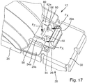
- FIG. 1 to 17 A first exemplary embodiment of an LED light module 20 according to the invention is shown.
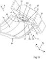
- This has at least one stop element 46, 48, which is arranged on the LED light module 20 and designed to position the LED light module 20 in an exact position relative to the optical unit 24 in at least one plane with a corresponding reference geometry 40, 42, 44 the optics unit 24 (cf. Figures 3 and 16 ) cooperate.
- two stop elements 46, 48 are provided. Through the interaction of the stop elements 46, 48 with the referencing geometry 40, 42, 44, the relative position between the optics unit 24 and the LED light module 20 that can be detachably attached to it can be predetermined precisely in an xy plane.
- the referencing geometry comprises a first stop surface 40, which acts in the x direction and extends in the y direction. Furthermore, the referencing geometry comprises two further V-shaped stop faces 42, 44, which each act in the x and y directions and each extend obliquely to the x direction and the y direction. The two V-shaped stop surfaces 42, 44 are formed offset in the y-direction from the first stop surface 40 on the optical element 24.
- the optics unit 24 has a base plate 24a on which the deflection element 26, which is designed as a reflector, is arranged.
- the base plate 24a and the deflection element 26 are formed as a single piece.
- the first abutment surface 40 and the further inclined abutment surfaces 42, 44 are preferably formed on a front edge section 24d of the base plate 24a directed in the direction of travel or x-direction.
- the stop elements are designed as referencing pins 46, 48 which are attached to the circuit board 28.
- the referencing pins 46, 48 are inserted into holes in the board 28 which are drilled with high precision with respect to the LEDs 22 and are fixed therein.
- the pins 46, 48 can be fixed on the circuit board 28, for example, by means of a press fit, adhesive, lacquer or in some other way.
- the referencing pin 48 when the LED light module 20 is mounted on the optics unit 24, has an operative connection with the abutting surfaces 42, 44 of the optics unit 24 and ensures that the LED light module 20 in the x-direction and in the y-direction is positioned relative to the optical unit 24.
- the referencing pin 46 interacts with the stop surface 40 and ensures that the LED light module 20 can no longer be rotated about a vertical axis of rotation, which is defined by a longitudinal axis of the referencing pin 48 (parallel to the z-axis) is.
- the stop elements 46, 48 are not formed on the board 28, but in the form of referencing surfaces of a referencing part 60 made of plastic (cf. Figure 5 ).
- the referencing part 60 is fastened to the LED light module 20 or with respect to the circuit board 28, the heat sink 30 and the adapter 32, for example by means of one of the screws 34 which is guided through an opening 62 in the referencing part 60.
- Other types of fastening are also conceivable.
- the referencing surfaces 46, 48 are in particular designed as distal end surfaces of conically shaped or tapered projections 64 directed in the negative x direction.
- the reference part 60 can be produced by means of an injection molding process. If the adapter 32 is made of plastic, the referencing part 60 as an integral part of the adapter 32 could be formed in one piece with it and produced together with it.
- the adapter 32 has two spring elements 50 which, when the LED light module 20 is mounted, the stop elements 46, 48 of the LED light module 20 for the positionally accurate positioning of the LED light module 20 relative to the optical unit 24 against the referencing geometry 40, 42, 44 Press the optics unit 24.
- the spring elements 50 are each formed, for example, as a leaf spring or spring clip in one piece with the adapter 32 and are supported on the optical unit 24. They are preferably supported on a rear edge section 24c (directed in the negative x direction) of the base plate 24a of the optical unit 24.
- the base plate 24a is then, as it were, clamped between the stop elements 46, 48 and the spring elements 50. Due to the interaction of the spring elements 50 on the one hand and the stop elements 46, 48 and the referencing geometry 40, 42, 44 on the other hand, the LED light module 20 is positioned in the xy plane relative to the optics unit 24.
- the adapter 32 also has a fastening arrangement for releasably fastening the precisely positioned LED light module 20 to the optics unit 24.
- the fastening arrangement is designed in particular, the LED light module 20 in the to hold the z direction on the optical unit 24.
- the fastening arrangement has a first holding element 56 articulated on the adapter 32 in an articulation area 78 with a holding arm 56a resilient in a z direction and an active surface 56b formed thereon, which extends essentially in a plane parallel to the xy plane and which holds the precisely positioned LED light module 20 in the z-direction on the optics unit 24, the active surface 56b acting on a partial area of the optics unit 24 which, when the precisely positioned LED light module 20 is located, lies opposite the partial area of the optics unit 24 on which the at least one Stop element 46, 48 acts.
- more than one holding element 56 or the holding arm 56a can also be provided.
- the articulation area 78 of the holding arm 56a is spaced apart from the stop elements 46, 48 or the front edge area 24d of the base plate 24a.
- the active surface 56b of the holding arm 56a can also act on a partial area of the optical unit 24 which lies in a rear edge area 24c of the base plate 24a.
- the holding arm 56a is designed to be resilient in the z direction, so that when the LED light module 20 is mounted on the optical unit 24, the base plate 24a of the optical unit 24 can be pushed under the holding arm 56a without problems and the light module 20 can nevertheless be securely mounted in z Direction is held relative to the base plate 24a.
- the fastening arrangement has two second holding elements 52, 54 articulated on the adapter 32 in an articulation area 78, each with a holding arm 52a, 54a resilient in the z direction and an active surface 52b, 54b formed thereon.
- a second holding element or more than the two holding elements 52, 54 or two holding arms 52a, 54a can be provided.
- the articulation area 78 of the holding arms 52a, 54a is spaced apart from the stop elements 46, 48 or the front edge area 24d of the base plate 24a.
- the articulation area 78 of the holding elements 52, 54, 56 is preferably located on a rear area of the adapter directed against the light exit direction 6 32 arranged so that the articulation region 78 is arranged behind the rear edge region 24c of the base plate 24a when the LED light module 20 is positioned precisely on the optical unit 24.
- This has, for example DE 10 2017 122 560 the advantage that there are no holding elements 52, 54 on the front edge region 24d of the base plate 24a in the light emission region of the light reflected by the deflection element 26, which could disrupt the light distribution.
- the active surfaces 52b, 54b extend essentially in a plane parallel to the xy plane and hold the precisely positioned LED light module 20 in the z direction on the optical unit 24.
- the active surfaces 52b, 54b of the holding arms 52a, 52b act on a partial area the optical unit 24, which in this example lies between the articulation area 78 of the holding elements 52, 54 on the adapter 32 and the stop elements 46, 48 of the LED light module 20. More specifically, the active surfaces 52b, 54b of the holding arms 52a, 52b act on a partial area of the base plate 24a which lies between the front edge area and the rear edge area of the base plate 24a.
- two passage openings 80 are formed in the deflection element 26 adjacent to the base plate 24a, through which the resilient holding arms 52a, 54a extend when the LED light module 20 is held on the optical unit 24, so that the partial area of the base plate 24a on which the active surfaces are located 52b, 54b of the resilient holding arms 52a, 54a of the second holding elements 52, 54 act on a side of the deflection element 26 which is opposite the articulation region 78 of the resilient holding arms 52a, 54a.
- This enables a particularly secure mounting of the LED light module 20 on the optics unit 24.
- the fastening arrangement or the holding arms 52, 54, 56 and the spring elements 50 are formed in one piece with the adapter 32.
- the articulation region 78 of the holding arms 52, 54, 56 and the spring elements 50 are preferably arranged next to one another on the same side of the adapter 32. When the LED light module 20 is mounted, this side is located on the rear edge region of the base plate 24a of the optical unit 24.
- the interaction of the holding arms 52, 54, 56 makes the adapter 32 and with it the entire LED light module 20 special held securely and reliably in the z direction on the base plate 24a of the optical unit 24.
- the LED light module 20 is preassembled by attaching the adapter 32 and the circuit board 28 to the heat sink 30.
- the referencing part 60 with the referencing surfaces 46, 48 can be attached to the circuit board 28 beforehand.
- the referencing part 60 can also be attached to the heat sink 30 separately or together with the adapter 32 and the circuit board 28.
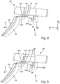
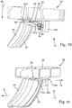
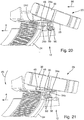
- the pre-assembled LED light module 20 is manually placed on the optics unit 24, in particular on a rear edge section 24c of the base plate 24a (cf. Figures 8 and 19th ) and releasably attached to it by a combined translation / swivel movement (cf. Figures 9 to 11 or 20 to 22).
- the light module 20 according to FIG Figures 18 to 22 only a first central holding element 56 with a holding arm 56a, which is arranged between the two spring elements 50.
- the LED light module 20 is held on the optical unit 24 solely by the holding arm 56a.
- the holding arm 56a also does not act on a partial area of the base plate 24a of the optical unit 24, but rather on a projection 24b which is attached to the deflection element 26 and projects rearward in the negative x direction.
- the preassembled LED light module 20 is first placed on the optical unit 24 from behind in a slightly inclined position with the front section of the light module 20 tilted slightly upwards (cf. Figures 8 and 19th ).
- a translatory movement of the obliquely placed light module 20 in the positive x direction is then carried out (cf. Figures 9 or 20).
- the translatory movement is indicated by an arrow 66.
- the active surfaces 56b; 52b, 54b of the holding arms 56a; 52a, 54a can be arranged on the underside of the partial area of the optical unit 24 on which they act in the assembled position. In the first exemplary embodiment, this is the underside of the base plate 24a of the optical unit 24 (cf.
- the holding element 56 comprises the rear edge region of the projection 24b, ie the active surface 56b of the holding arm 56a lies on the underside of the projection 24b (cf. Figure 10 ).
- the spring elements 50 in the first exemplary embodiment or the one spring element 50 (in the second exemplary embodiment) are elastically deformed against their spring force.
- the translational movement 66 is continued until the stop elements 46, 48 are arranged beyond (or in the positive x direction in front) the referencing geometry 40, 42, 44 of the optical unit 24.
- the LED light module 20 is now pivoted in a pivoting movement about an axis of rotation which is approximately formed by the rear edge region of the base plate 24a (cf. Figures 10 and 21st ). Due to the resilient design of the holding elements 52, 54, 56 in the z direction, the axis of rotation is not precisely defined.
- the pivoting movement is indicated in the figures by an arrow 68 and takes place counterclockwise, ie the front section of the LED light module 20 is moved in the negative z direction.
- the axis of rotation preferably runs parallel to the y-axis.
- the pivoting movement is ended when the underside of the LED light module 20 comes to rest on the upper side of the base plate 24a of the optical unit 24. Then the LED light module 20 is released. Due to the spring force of the prestressed spring elements 50, the light module 20 is moved relative to the optical unit 24 in the negative x-direction until the stop elements 46, 48 interact with the reference geometry 40, 42, 44 of the optical unit 24 (cf. Figures 11 and 22 ). The corresponding translatory movement is designated by reference numeral 70. The LED light module 20 is thus positioned and held in the xy plane relative to the optical unit 24. The detachable attachment of the light module 20 in the z direction to the optical unit 24 is carried out by the holding elements 56; 52, 54.
- the assembly of the LED headlight module 12 by placing and swiveling the LED light module 20 on the optical unit 24 can thus be carried out quickly and easily, with one hand and without visual contact (ie blind) even in very confined spaces. Due to the action of the holding arms 52a, 54a, 56a, the LED light module 20 is held securely and reliably in the z-direction on the optics unit 24, even when subjected to mechanical stress (for example vibrations and impacts), such as during operation of the motor vehicle on which the Headlight 2 is mounted with the LED headlight module 12, may occur.
- mechanical stress for example vibrations and impacts
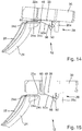
- the disassembly of the LED light module 20 from the optics unit 24 is described below with reference to FIG Figures 12 to 15 explained in more detail. It is basically carried out in the reverse order of assembly.
- the LED light module 20 is first moved forward in the positive x direction against the spring force of the at least one spring element 50 relative to the optical unit 24 (cf. Figure 12 ; Arrow 72). This releases the active engagement between the stop elements 46, 48 of the light module 20 and the corresponding referencing geometry 40, 42, 44 of the optical unit 24.
- the LED light module 20 is pivoted clockwise about the axis of rotation, the front section of the light module 20 moved in the positive z direction (cf. Figure 12 ; Arrow 74).
- the swivel movement is only a few degrees of angle, in any case significantly less than in previously known solutions, where the swivel movement is at least 15 °.
- the stop elements 46, 48 are arranged above the referencing geometry 40, 42, 44 (cf. Figure 13 )
- the inclined LED light module 20 is moved translationally in the negative x-direction (arrow 76).
- the rear edge section 24c of the base plate 24a of the optical unit 24 emerges from the holding arm 56a of the first holding element 56 or from the holding arms 52a, 54a of the second holding elements 52, 54 and the active surface 56b of the holding arm 56a slides along the underside of the projection 24b in Direction of the rear edge section and the active surfaces 52b, 54b of the holding arms 52a, 54a slide along the underside of the base plate 24a in the direction of the rear edge section 24c (cf. Figure 14 ).
- the LED light module 20 can then be lifted off the optics unit 24 (cf. Figure 15 ); disassembly is now complete.
Landscapes
- Engineering & Computer Science (AREA)
- General Engineering & Computer Science (AREA)
- Physics & Mathematics (AREA)
- Microelectronics & Electronic Packaging (AREA)
- Optics & Photonics (AREA)
- Non-Portable Lighting Devices Or Systems Thereof (AREA)
Applications Claiming Priority (1)
| Application Number | Priority Date | Filing Date | Title |
|---|---|---|---|
| DE202018107292.7U DE202018107292U1 (de) | 2018-12-19 | 2018-12-19 | LED-Scheinwerfermodul und LED-Lichtmodul zur Verwendung in einem solchen LED-Scheinwerfermodul |
Publications (2)
| Publication Number | Publication Date |
|---|---|
| EP3671014A1 true EP3671014A1 (fr) | 2020-06-24 |
| EP3671014B1 EP3671014B1 (fr) | 2023-01-25 |
Family
ID=68242447
Family Applications (1)
| Application Number | Title | Priority Date | Filing Date |
|---|---|---|---|
| EP19202186.3A Active EP3671014B1 (fr) | 2018-12-19 | 2019-10-09 | Module de phares à del et module lumineux à del destiné à être utilisé dans un tel module de phares à del |
Country Status (2)
| Country | Link |
|---|---|
| EP (1) | EP3671014B1 (fr) |
| DE (1) | DE202018107292U1 (fr) |
Families Citing this family (4)
| Publication number | Priority date | Publication date | Assignee | Title |
|---|---|---|---|---|
| DE102020108894A1 (de) | 2020-03-31 | 2021-09-30 | HELLA GmbH & Co. KGaA | Lichtmodul, Scheinwerfer, Kraftfahrzeug sowie Verfahren zum Herstellen des Lichtmoduls |
| DE102022108283B4 (de) | 2022-04-06 | 2026-04-23 | Marelli Germany Gmbh | Lichtmodul, Kraftfahrzeugbeleuchtungseinrichtung mit einem solchen Lichtmodul und Verfahren zur Montage eines optischen Systems eines Lichtmoduls an einem Lichtquellenmodul des Lichtmoduls |
| CN119836543A (zh) | 2022-08-03 | 2025-04-15 | 亮锐有限责任公司 | 头灯组件和组装的方法 |
| DE102023136305A1 (de) * | 2023-12-21 | 2025-06-26 | HELLA GmbH & Co. KGaA | Lichtmodul für eine Kraftfahrzeug-Beleuchtungseinrichtung |
Citations (8)
| Publication number | Priority date | Publication date | Assignee | Title |
|---|---|---|---|---|
| US20080008427A1 (en) * | 2006-07-07 | 2008-01-10 | Koito Manufacturing Co., Ltd. | Light emitting module and lighting device for vehicle |
| DE102007050893A1 (de) * | 2007-10-24 | 2009-04-30 | Continental Automotive Gmbh | Verfahren zum Positionieren und Montieren einer LED-Baueinheit sowie Positionierkörper hierfür |
| US20100067251A1 (en) * | 2008-09-17 | 2010-03-18 | Ichikoh Industries, Ltd. | Vehicle lighting device |
| US20120007506A1 (en) * | 2010-07-12 | 2012-01-12 | Koito Manufacturing Co., Ltd. | Vehicular lamp |
| EP2915698A1 (fr) * | 2014-03-06 | 2015-09-09 | HDO -Druckguss- und Oberflächentechnik GmbH | Lampe à del |
| US20150308652A1 (en) | 2012-11-30 | 2015-10-29 | Valeo lluminacion | Motor vehicle lighting and/or signalling device |
| DE102016119792A1 (de) | 2016-10-18 | 2018-04-19 | Automotive Lighting Reutlingen Gmbh | Verfahren zur Anordnung eines Schaltungsträgers und Beleuchtungseinrichtung für ein Kraftfahrzeug mit einem nach diesem Verfahren angeordneten Schaltungsträger |
| DE102017122560A1 (de) | 2017-09-28 | 2019-03-28 | Automotive Lighting Reutlingen Gmbh | LED-Scheinwerfermodul |
Family Cites Families (2)
| Publication number | Priority date | Publication date | Assignee | Title |
|---|---|---|---|---|
| CN108431490B (zh) * | 2016-01-12 | 2020-11-03 | 亮锐控股有限公司 | 具有准确光学元件定位的照明布置 |
| DE102016113937A1 (de) * | 2016-07-28 | 2018-02-01 | HELLA GmbH & Co. KGaA | Lichtmodul für eine Beleuchtungseinrichtung eines Fahrzeugs |
-
2018
- 2018-12-19 DE DE202018107292.7U patent/DE202018107292U1/de active Active
-
2019
- 2019-10-09 EP EP19202186.3A patent/EP3671014B1/fr active Active
Patent Citations (8)
| Publication number | Priority date | Publication date | Assignee | Title |
|---|---|---|---|---|
| US20080008427A1 (en) * | 2006-07-07 | 2008-01-10 | Koito Manufacturing Co., Ltd. | Light emitting module and lighting device for vehicle |
| DE102007050893A1 (de) * | 2007-10-24 | 2009-04-30 | Continental Automotive Gmbh | Verfahren zum Positionieren und Montieren einer LED-Baueinheit sowie Positionierkörper hierfür |
| US20100067251A1 (en) * | 2008-09-17 | 2010-03-18 | Ichikoh Industries, Ltd. | Vehicle lighting device |
| US20120007506A1 (en) * | 2010-07-12 | 2012-01-12 | Koito Manufacturing Co., Ltd. | Vehicular lamp |
| US20150308652A1 (en) | 2012-11-30 | 2015-10-29 | Valeo lluminacion | Motor vehicle lighting and/or signalling device |
| EP2915698A1 (fr) * | 2014-03-06 | 2015-09-09 | HDO -Druckguss- und Oberflächentechnik GmbH | Lampe à del |
| DE102016119792A1 (de) | 2016-10-18 | 2018-04-19 | Automotive Lighting Reutlingen Gmbh | Verfahren zur Anordnung eines Schaltungsträgers und Beleuchtungseinrichtung für ein Kraftfahrzeug mit einem nach diesem Verfahren angeordneten Schaltungsträger |
| DE102017122560A1 (de) | 2017-09-28 | 2019-03-28 | Automotive Lighting Reutlingen Gmbh | LED-Scheinwerfermodul |
Also Published As
| Publication number | Publication date |
|---|---|
| DE202018107292U1 (de) | 2020-03-23 |
| EP3671014B1 (fr) | 2023-01-25 |
Similar Documents
| Publication | Publication Date | Title |
|---|---|---|
| EP2888519B1 (fr) | Procédé de positionnement d'un élément modeleur de lumière | |
| EP3671014B1 (fr) | Module de phares à del et module lumineux à del destiné à être utilisé dans un tel module de phares à del | |
| WO2019063298A1 (fr) | Module de projecteur à del | |
| DE102012213844B4 (de) | Lichtmodul für KFZ-Scheinwerfer mit zwei Optikeinheiten und zugehörigen Befestigungseinrichtungen | |
| EP2317213B1 (fr) | Module de diode luminescente d'un dispositif d'éclairage de véhicule automobile et dispositif d'éclairage de véhicule automobile | |
| EP2820348B1 (fr) | Dispositif d'illumination | |
| EP3339720B1 (fr) | Ensemble d'optique primaire destiné à être utilisé dans un dispositif d'éclairage du véhicule automobile et dispositif d'éclairage du véhicule automobile doté d'un tel ensemble d'optique primaire | |
| EP2488785B1 (fr) | Phare de projection pour véhicules | |
| WO2006066530A1 (fr) | Dispositif d'eclairage dote d'au moins une diode electroluminescente et phare de vehicule | |
| EP2915698A1 (fr) | Lampe à del | |
| EP3366984B1 (fr) | Dispositif d'éclairage d'un véhicule automobile | |
| EP2693109A2 (fr) | Module d'éclairage | |
| DE102021125553A1 (de) | Leuchten-Einheit | |
| EP2888520B1 (fr) | Module d'éclairage pour véhicule à moteur | |
| DE102006039705A1 (de) | Linsenvorsatz für einen Scheinwerfer | |
| WO2018161988A1 (fr) | Dispositif d'éclairage pour véhicules et procédé de montage | |
| AT17812U1 (de) | Leuchtvorrichtung für ein Kraftfahrzeug mit einem Leuchtmodul | |
| DE102021201873A1 (de) | Reflektor, leuchte, werkzeug, fahrzeug und verfahren zur herstellung einer leuchte | |
| DE102012219007B4 (de) | Beleuchtungseinrichtung für ein Kraftfahrzeug | |
| DE102022108281B4 (de) | Lichtmodul und Kraftfahrzeugbeleuchtungseinrichtung mit einem solchen Lichtmodul | |
| WO2023088815A1 (fr) | Module lumineux pour un dispositif d'éclairage d'un véhicule | |
| DE102016108260A1 (de) | Verfahren zur Anordnung eines Schaltungsträgers und Vorrichtung zur Anordnung eines Schaltungsträgers | |
| EP4224057A1 (fr) | Module d'éclairage, dispositif d'éclairage de véhicule automobile et procédé de fabrication | |
| DE102022108283B4 (de) | Lichtmodul, Kraftfahrzeugbeleuchtungseinrichtung mit einem solchen Lichtmodul und Verfahren zur Montage eines optischen Systems eines Lichtmoduls an einem Lichtquellenmodul des Lichtmoduls | |
| DE102021124889A1 (de) | Lichtmodul mit einer Befestigungseinrichtung |
Legal Events
| Date | Code | Title | Description |
|---|---|---|---|
| PUAI | Public reference made under article 153(3) epc to a published international application that has entered the european phase |
Free format text: ORIGINAL CODE: 0009012 |
|
| STAA | Information on the status of an ep patent application or granted ep patent |
Free format text: STATUS: THE APPLICATION HAS BEEN PUBLISHED |
|
| AK | Designated contracting states |
Kind code of ref document: A1 Designated state(s): AL AT BE BG CH CY CZ DE DK EE ES FI FR GB GR HR HU IE IS IT LI LT LU LV MC MK MT NL NO PL PT RO RS SE SI SK SM TR |
|
| AX | Request for extension of the european patent |
Extension state: BA ME |
|
| STAA | Information on the status of an ep patent application or granted ep patent |
Free format text: STATUS: REQUEST FOR EXAMINATION WAS MADE |
|
| 17P | Request for examination filed |
Effective date: 20201208 |
|
| RBV | Designated contracting states (corrected) |
Designated state(s): AL AT BE BG CH CY CZ DE DK EE ES FI FR GB GR HR HU IE IS IT LI LT LU LV MC MK MT NL NO PL PT RO RS SE SI SK SM TR |
|
| GRAP | Despatch of communication of intention to grant a patent |
Free format text: ORIGINAL CODE: EPIDOSNIGR1 |
|
| STAA | Information on the status of an ep patent application or granted ep patent |
Free format text: STATUS: GRANT OF PATENT IS INTENDED |
|
| INTG | Intention to grant announced |
Effective date: 20221031 |
|
| GRAS | Grant fee paid |
Free format text: ORIGINAL CODE: EPIDOSNIGR3 |
|
| GRAA | (expected) grant |
Free format text: ORIGINAL CODE: 0009210 |
|
| STAA | Information on the status of an ep patent application or granted ep patent |
Free format text: STATUS: THE PATENT HAS BEEN GRANTED |
|
| AK | Designated contracting states |
Kind code of ref document: B1 Designated state(s): AL AT BE BG CH CY CZ DE DK EE ES FI FR GB GR HR HU IE IS IT LI LT LU LV MC MK MT NL NO PL PT RO RS SE SI SK SM TR |
|
| REG | Reference to a national code |
Ref country code: GB Ref legal event code: FG4D Free format text: NOT ENGLISH |
|
| REG | Reference to a national code |
Ref country code: CH Ref legal event code: EP |
|
| REG | Reference to a national code |
Ref country code: AT Ref legal event code: REF Ref document number: 1546131 Country of ref document: AT Kind code of ref document: T Effective date: 20230215 Ref country code: IE Ref legal event code: FG4D Free format text: LANGUAGE OF EP DOCUMENT: GERMAN |
|
| REG | Reference to a national code |
Ref country code: DE Ref legal event code: R096 Ref document number: 502019006860 Country of ref document: DE |
|
| REG | Reference to a national code |
Ref country code: LT Ref legal event code: MG9D |
|
| REG | Reference to a national code |
Ref country code: NL Ref legal event code: MP Effective date: 20230125 |
|
| PG25 | Lapsed in a contracting state [announced via postgrant information from national office to epo] |
Ref country code: NL Free format text: LAPSE BECAUSE OF FAILURE TO SUBMIT A TRANSLATION OF THE DESCRIPTION OR TO PAY THE FEE WITHIN THE PRESCRIBED TIME-LIMIT Effective date: 20230125 |
|
| PG25 | Lapsed in a contracting state [announced via postgrant information from national office to epo] |
Ref country code: RS Free format text: LAPSE BECAUSE OF FAILURE TO SUBMIT A TRANSLATION OF THE DESCRIPTION OR TO PAY THE FEE WITHIN THE PRESCRIBED TIME-LIMIT Effective date: 20230125 Ref country code: PT Free format text: LAPSE BECAUSE OF FAILURE TO SUBMIT A TRANSLATION OF THE DESCRIPTION OR TO PAY THE FEE WITHIN THE PRESCRIBED TIME-LIMIT Effective date: 20230525 Ref country code: NO Free format text: LAPSE BECAUSE OF FAILURE TO SUBMIT A TRANSLATION OF THE DESCRIPTION OR TO PAY THE FEE WITHIN THE PRESCRIBED TIME-LIMIT Effective date: 20230425 Ref country code: LV Free format text: LAPSE BECAUSE OF FAILURE TO SUBMIT A TRANSLATION OF THE DESCRIPTION OR TO PAY THE FEE WITHIN THE PRESCRIBED TIME-LIMIT Effective date: 20230125 Ref country code: LT Free format text: LAPSE BECAUSE OF FAILURE TO SUBMIT A TRANSLATION OF THE DESCRIPTION OR TO PAY THE FEE WITHIN THE PRESCRIBED TIME-LIMIT Effective date: 20230125 Ref country code: HR Free format text: LAPSE BECAUSE OF FAILURE TO SUBMIT A TRANSLATION OF THE DESCRIPTION OR TO PAY THE FEE WITHIN THE PRESCRIBED TIME-LIMIT Effective date: 20230125 Ref country code: ES Free format text: LAPSE BECAUSE OF FAILURE TO SUBMIT A TRANSLATION OF THE DESCRIPTION OR TO PAY THE FEE WITHIN THE PRESCRIBED TIME-LIMIT Effective date: 20230125 |
|
| PG25 | Lapsed in a contracting state [announced via postgrant information from national office to epo] |
Ref country code: SE Free format text: LAPSE BECAUSE OF FAILURE TO SUBMIT A TRANSLATION OF THE DESCRIPTION OR TO PAY THE FEE WITHIN THE PRESCRIBED TIME-LIMIT Effective date: 20230125 Ref country code: PL Free format text: LAPSE BECAUSE OF FAILURE TO SUBMIT A TRANSLATION OF THE DESCRIPTION OR TO PAY THE FEE WITHIN THE PRESCRIBED TIME-LIMIT Effective date: 20230125 Ref country code: IS Free format text: LAPSE BECAUSE OF FAILURE TO SUBMIT A TRANSLATION OF THE DESCRIPTION OR TO PAY THE FEE WITHIN THE PRESCRIBED TIME-LIMIT Effective date: 20230525 Ref country code: GR Free format text: LAPSE BECAUSE OF FAILURE TO SUBMIT A TRANSLATION OF THE DESCRIPTION OR TO PAY THE FEE WITHIN THE PRESCRIBED TIME-LIMIT Effective date: 20230426 Ref country code: FI Free format text: LAPSE BECAUSE OF FAILURE TO SUBMIT A TRANSLATION OF THE DESCRIPTION OR TO PAY THE FEE WITHIN THE PRESCRIBED TIME-LIMIT Effective date: 20230125 |
|
| REG | Reference to a national code |
Ref country code: DE Ref legal event code: R097 Ref document number: 502019006860 Country of ref document: DE |
|
| PG25 | Lapsed in a contracting state [announced via postgrant information from national office to epo] |
Ref country code: SM Free format text: LAPSE BECAUSE OF FAILURE TO SUBMIT A TRANSLATION OF THE DESCRIPTION OR TO PAY THE FEE WITHIN THE PRESCRIBED TIME-LIMIT Effective date: 20230125 Ref country code: RO Free format text: LAPSE BECAUSE OF FAILURE TO SUBMIT A TRANSLATION OF THE DESCRIPTION OR TO PAY THE FEE WITHIN THE PRESCRIBED TIME-LIMIT Effective date: 20230125 Ref country code: EE Free format text: LAPSE BECAUSE OF FAILURE TO SUBMIT A TRANSLATION OF THE DESCRIPTION OR TO PAY THE FEE WITHIN THE PRESCRIBED TIME-LIMIT Effective date: 20230125 Ref country code: DK Free format text: LAPSE BECAUSE OF FAILURE TO SUBMIT A TRANSLATION OF THE DESCRIPTION OR TO PAY THE FEE WITHIN THE PRESCRIBED TIME-LIMIT Effective date: 20230125 Ref country code: CZ Free format text: LAPSE BECAUSE OF FAILURE TO SUBMIT A TRANSLATION OF THE DESCRIPTION OR TO PAY THE FEE WITHIN THE PRESCRIBED TIME-LIMIT Effective date: 20230125 |
|
| PG25 | Lapsed in a contracting state [announced via postgrant information from national office to epo] |
Ref country code: SK Free format text: LAPSE BECAUSE OF FAILURE TO SUBMIT A TRANSLATION OF THE DESCRIPTION OR TO PAY THE FEE WITHIN THE PRESCRIBED TIME-LIMIT Effective date: 20230125 |
|
| PLBE | No opposition filed within time limit |
Free format text: ORIGINAL CODE: 0009261 |
|
| STAA | Information on the status of an ep patent application or granted ep patent |
Free format text: STATUS: NO OPPOSITION FILED WITHIN TIME LIMIT |
|
| 26N | No opposition filed |
Effective date: 20231026 |
|
| PG25 | Lapsed in a contracting state [announced via postgrant information from national office to epo] |
Ref country code: SI Free format text: LAPSE BECAUSE OF FAILURE TO SUBMIT A TRANSLATION OF THE DESCRIPTION OR TO PAY THE FEE WITHIN THE PRESCRIBED TIME-LIMIT Effective date: 20230125 |
|
| PG25 | Lapsed in a contracting state [announced via postgrant information from national office to epo] |
Ref country code: IT Free format text: LAPSE BECAUSE OF FAILURE TO SUBMIT A TRANSLATION OF THE DESCRIPTION OR TO PAY THE FEE WITHIN THE PRESCRIBED TIME-LIMIT Effective date: 20230125 Ref country code: MC Free format text: LAPSE BECAUSE OF FAILURE TO SUBMIT A TRANSLATION OF THE DESCRIPTION OR TO PAY THE FEE WITHIN THE PRESCRIBED TIME-LIMIT Effective date: 20230125 |
|
| REG | Reference to a national code |
Ref country code: CH Ref legal event code: PL |
|
| REG | Reference to a national code |
Ref country code: BE Ref legal event code: MM Effective date: 20231031 |
|
| PG25 | Lapsed in a contracting state [announced via postgrant information from national office to epo] |
Ref country code: LU Free format text: LAPSE BECAUSE OF NON-PAYMENT OF DUE FEES Effective date: 20231009 |
|
| GBPC | Gb: european patent ceased through non-payment of renewal fee |
Effective date: 20231009 |
|
| PG25 | Lapsed in a contracting state [announced via postgrant information from national office to epo] |
Ref country code: LU Free format text: LAPSE BECAUSE OF NON-PAYMENT OF DUE FEES Effective date: 20231009 |
|
| PG25 | Lapsed in a contracting state [announced via postgrant information from national office to epo] |
Ref country code: GB Free format text: LAPSE BECAUSE OF NON-PAYMENT OF DUE FEES Effective date: 20231009 |
|
| PG25 | Lapsed in a contracting state [announced via postgrant information from national office to epo] |
Ref country code: CH Free format text: LAPSE BECAUSE OF NON-PAYMENT OF DUE FEES Effective date: 20231031 |
|
| PG25 | Lapsed in a contracting state [announced via postgrant information from national office to epo] |
Ref country code: GB Free format text: LAPSE BECAUSE OF NON-PAYMENT OF DUE FEES Effective date: 20231009 Ref country code: CH Free format text: LAPSE BECAUSE OF NON-PAYMENT OF DUE FEES Effective date: 20231031 |
|
| PG25 | Lapsed in a contracting state [announced via postgrant information from national office to epo] |
Ref country code: BE Free format text: LAPSE BECAUSE OF NON-PAYMENT OF DUE FEES Effective date: 20231031 |
|
| PG25 | Lapsed in a contracting state [announced via postgrant information from national office to epo] |
Ref country code: IE Free format text: LAPSE BECAUSE OF NON-PAYMENT OF DUE FEES Effective date: 20231009 |
|
| PGFP | Annual fee paid to national office [announced via postgrant information from national office to epo] |
Ref country code: FR Payment date: 20240919 Year of fee payment: 6 |
|
| PG25 | Lapsed in a contracting state [announced via postgrant information from national office to epo] |
Ref country code: IE Free format text: LAPSE BECAUSE OF NON-PAYMENT OF DUE FEES Effective date: 20231009 |
|
| PG25 | Lapsed in a contracting state [announced via postgrant information from national office to epo] |
Ref country code: BG Free format text: LAPSE BECAUSE OF FAILURE TO SUBMIT A TRANSLATION OF THE DESCRIPTION OR TO PAY THE FEE WITHIN THE PRESCRIBED TIME-LIMIT Effective date: 20230125 |
|
| PG25 | Lapsed in a contracting state [announced via postgrant information from national office to epo] |
Ref country code: BG Free format text: LAPSE BECAUSE OF FAILURE TO SUBMIT A TRANSLATION OF THE DESCRIPTION OR TO PAY THE FEE WITHIN THE PRESCRIBED TIME-LIMIT Effective date: 20230125 |
|
| PGFP | Annual fee paid to national office [announced via postgrant information from national office to epo] |
Ref country code: AT Payment date: 20240923 Year of fee payment: 6 |
|
| PG25 | Lapsed in a contracting state [announced via postgrant information from national office to epo] |
Ref country code: CY Free format text: LAPSE BECAUSE OF FAILURE TO SUBMIT A TRANSLATION OF THE DESCRIPTION OR TO PAY THE FEE WITHIN THE PRESCRIBED TIME-LIMIT; INVALID AB INITIO Effective date: 20191009 |
|
| REG | Reference to a national code |
Ref country code: DE Ref legal event code: R081 Ref document number: 502019006860 Country of ref document: DE Owner name: MARELLI GERMANY GMBH, DE Free format text: FORMER OWNER: AUTOMOTIVE LIGHTING REUTLINGEN GMBH, 72762 REUTLINGEN, DE |
|
| PG25 | Lapsed in a contracting state [announced via postgrant information from national office to epo] |
Ref country code: HU Free format text: LAPSE BECAUSE OF FAILURE TO SUBMIT A TRANSLATION OF THE DESCRIPTION OR TO PAY THE FEE WITHIN THE PRESCRIBED TIME-LIMIT; INVALID AB INITIO Effective date: 20191009 |
|
| REG | Reference to a national code |
Ref country code: DE Ref legal event code: R084 Ref document number: 502019006860 Country of ref document: DE |
|
| REG | Reference to a national code |
Ref country code: AT Ref legal event code: HC Ref document number: 1546131 Country of ref document: AT Kind code of ref document: T Owner name: MARELLI GERMANY GMBH, DE Effective date: 20250903 |
|
| PG25 | Lapsed in a contracting state [announced via postgrant information from national office to epo] |
Ref country code: TR Free format text: LAPSE BECAUSE OF FAILURE TO SUBMIT A TRANSLATION OF THE DESCRIPTION OR TO PAY THE FEE WITHIN THE PRESCRIBED TIME-LIMIT Effective date: 20230125 |
|
| PGFP | Annual fee paid to national office [announced via postgrant information from national office to epo] |
Ref country code: DE Payment date: 20250923 Year of fee payment: 7 |