EP3671030B1 - Verbindungsvorrichtung für einen beleuchtungskörper - Google Patents
Verbindungsvorrichtung für einen beleuchtungskörper Download PDFInfo
- Publication number
- EP3671030B1 EP3671030B1 EP19217643.6A EP19217643A EP3671030B1 EP 3671030 B1 EP3671030 B1 EP 3671030B1 EP 19217643 A EP19217643 A EP 19217643A EP 3671030 B1 EP3671030 B1 EP 3671030B1
- Authority
- EP
- European Patent Office
- Prior art keywords
- connection
- luminaire
- housing
- board
- electronic
- Prior art date
- Legal status (The legal status is an assumption and is not a legal conclusion. Google has not performed a legal analysis and makes no representation as to the accuracy of the status listed.)
- Active
Links
Images




Classifications
-
- F—MECHANICAL ENGINEERING; LIGHTING; HEATING; WEAPONS; BLASTING
- F21—LIGHTING
- F21V—FUNCTIONAL FEATURES OR DETAILS OF LIGHTING DEVICES OR SYSTEMS THEREOF; STRUCTURAL COMBINATIONS OF LIGHTING DEVICES WITH OTHER ARTICLES, NOT OTHERWISE PROVIDED FOR
- F21V21/00—Supporting, suspending, or attaching arrangements for lighting devices; Hand grips
- F21V21/002—Supporting, suspending, or attaching arrangements for lighting devices; Hand grips making direct electrical contact, e.g. by piercing
-
- F—MECHANICAL ENGINEERING; LIGHTING; HEATING; WEAPONS; BLASTING
- F21—LIGHTING
- F21V—FUNCTIONAL FEATURES OR DETAILS OF LIGHTING DEVICES OR SYSTEMS THEREOF; STRUCTURAL COMBINATIONS OF LIGHTING DEVICES WITH OTHER ARTICLES, NOT OTHERWISE PROVIDED FOR
- F21V21/00—Supporting, suspending, or attaching arrangements for lighting devices; Hand grips
- F21V21/02—Wall, ceiling, or floor bases; Fixing pendants or arms to the bases
- F21V21/03—Ceiling bases, e.g. ceiling roses
-
- F—MECHANICAL ENGINEERING; LIGHTING; HEATING; WEAPONS; BLASTING
- F21—LIGHTING
- F21S—NON-PORTABLE LIGHTING DEVICES; SYSTEMS THEREOF; VEHICLE LIGHTING DEVICES SPECIALLY ADAPTED FOR VEHICLE EXTERIORS
- F21S8/00—Lighting devices intended for fixed installation
- F21S8/02—Lighting devices intended for fixed installation of recess-mounted type, e.g. downlighters
- F21S8/024—Lighting devices intended for fixed installation of recess-mounted type, e.g. downlighters intended to be recessed in a wall or like vertical structure, e.g. building facade
-
- F—MECHANICAL ENGINEERING; LIGHTING; HEATING; WEAPONS; BLASTING
- F21—LIGHTING
- F21V—FUNCTIONAL FEATURES OR DETAILS OF LIGHTING DEVICES OR SYSTEMS THEREOF; STRUCTURAL COMBINATIONS OF LIGHTING DEVICES WITH OTHER ARTICLES, NOT OTHERWISE PROVIDED FOR
- F21V23/00—Arrangement of electric circuit elements in or on lighting devices
- F21V23/003—Arrangement of electric circuit elements in or on lighting devices the elements being electronics drivers or controllers for operating the light source, e.g. for a LED array
- F21V23/004—Arrangement of electric circuit elements in or on lighting devices the elements being electronics drivers or controllers for operating the light source, e.g. for a LED array arranged on a substrate, e.g. a printed circuit board
- F21V23/006—Arrangement of electric circuit elements in or on lighting devices the elements being electronics drivers or controllers for operating the light source, e.g. for a LED array arranged on a substrate, e.g. a printed circuit board the substrate being distinct from the light source holder
-
- F—MECHANICAL ENGINEERING; LIGHTING; HEATING; WEAPONS; BLASTING
- F21—LIGHTING
- F21V—FUNCTIONAL FEATURES OR DETAILS OF LIGHTING DEVICES OR SYSTEMS THEREOF; STRUCTURAL COMBINATIONS OF LIGHTING DEVICES WITH OTHER ARTICLES, NOT OTHERWISE PROVIDED FOR
- F21V23/00—Arrangement of electric circuit elements in or on lighting devices
- F21V23/06—Arrangement of electric circuit elements in or on lighting devices the elements being coupling devices, e.g. connectors
-
- H—ELECTRICITY
- H02—GENERATION; CONVERSION OR DISTRIBUTION OF ELECTRIC POWER
- H02G—INSTALLATION OF ELECTRIC CABLES OR LINES, OR OF COMBINED OPTICAL AND ELECTRIC CABLES OR LINES
- H02G3/00—Installations of electric cables or lines or protective tubing therefor in or on buildings, equivalent structures or vehicles
- H02G3/02—Details
- H02G3/08—Distribution boxes; Connection or junction boxes
- H02G3/18—Distribution boxes; Connection or junction boxes providing line outlets
- H02G3/20—Ceiling roses or other lighting sets
-
- H—ELECTRICITY
- H05—ELECTRIC TECHNIQUES NOT OTHERWISE PROVIDED FOR
- H05B—ELECTRIC HEATING; ELECTRIC LIGHT SOURCES NOT OTHERWISE PROVIDED FOR; CIRCUIT ARRANGEMENTS FOR ELECTRIC LIGHT SOURCES, IN GENERAL
- H05B47/00—Circuit arrangements for operating light sources in general, i.e. where the type of light source is not relevant
- H05B47/10—Controlling the light source
- H05B47/175—Controlling the light source by remote control
- H05B47/19—Controlling the light source by remote control via wireless transmission
-
- F—MECHANICAL ENGINEERING; LIGHTING; HEATING; WEAPONS; BLASTING
- F21—LIGHTING
- F21V—FUNCTIONAL FEATURES OR DETAILS OF LIGHTING DEVICES OR SYSTEMS THEREOF; STRUCTURAL COMBINATIONS OF LIGHTING DEVICES WITH OTHER ARTICLES, NOT OTHERWISE PROVIDED FOR
- F21V23/00—Arrangement of electric circuit elements in or on lighting devices
- F21V23/04—Arrangement of electric circuit elements in or on lighting devices the elements being switches
- F21V23/0435—Arrangement of electric circuit elements in or on lighting devices the elements being switches activated by remote control means
-
- F—MECHANICAL ENGINEERING; LIGHTING; HEATING; WEAPONS; BLASTING
- F21—LIGHTING
- F21V—FUNCTIONAL FEATURES OR DETAILS OF LIGHTING DEVICES OR SYSTEMS THEREOF; STRUCTURAL COMBINATIONS OF LIGHTING DEVICES WITH OTHER ARTICLES, NOT OTHERWISE PROVIDED FOR
- F21V23/00—Arrangement of electric circuit elements in or on lighting devices
- F21V23/04—Arrangement of electric circuit elements in or on lighting devices the elements being switches
- F21V23/0442—Arrangement of electric circuit elements in or on lighting devices the elements being switches activated by means of a sensor, e.g. motion or photodetectors
- F21V23/045—Arrangement of electric circuit elements in or on lighting devices the elements being switches activated by means of a sensor, e.g. motion or photodetectors the sensor receiving a signal from a remote controller
Definitions
- the present invention relates to a connection device for a luminaire.
- DCL devices are mounted in recessed boxes themselves mounted in walls or ceilings and having predefined dimensions. DCL devices also have predefined dimensions depending on the boxes in which they are installed, and have a central duct intended to allow the insertion of a luminaire hooking screw. DCL devices are formed by a box containing electronic components and connection members.
- US 2018/115131 describes an electrical appliance connection device, comprising a zone for connection to an electrical network and a box forming an interior volume in which are integrated electrical supply members of the luminaire and a control and communication system.
- the invention intends to remedy by proposing a new connection device for a luminaire, the assembly and integration of connected functions of which are greatly facilitated.
- connection device for a luminaire comprising a box intended to be installed in an assembly space in a wall of a room, this device comprising a connection socket for a luminaire and a zone connection to an electrical network.
- the box forms an internal volume in which are integrated electrical supply members of the luminaire, connection devices between the luminaire connection socket and the connection area to the electrical network and a control and communication system with a device external to the connection device.
- the control and communication system comprises a radio-frequency communication antenna
- the device comprises a front face integral with the housing and configured to protrude outside the mounting space, the antenna being provided in a zone of the device located in a volume delimited by the front face, and the front face has a wall provided with a reduction in thickness forming a cavity oriented on an internal side of the housing and in which the antenna of communication
- the DCL box already contains all the components necessary for carrying out remote controls.
- the ease of assembly is greatly improved, since the intervention of an electrician is no longer necessary to connect the communication systems.
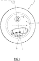
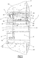
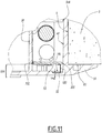
- the figure 1 shows a connection device 2 for a luminaire not shown, comprising a box 4 intended to be installed in a mounting space 6 visible to figures 5 and 11 , provided in a wall 8 of a room in a room not shown.
- This connection device 2 commonly called “DCL” for Luminaire Connection Device, comprises a standardized connection socket 10 for the luminaire and a connection area 12 to an electrical network. The purpose of this device is to facilitate the installation of lighting for the occupant of the room.
- connection socket 10 is located on a front face 14 of the housing 4, which protrudes outside the wall 8, and which comprises a flange 140 which extends against the wall 8.
- the connection area 12 is located on a rear face 16 of box 4 and located in the assembly space 6.
- the case 4 has a cylindrical shape with a circular section centered on a central axis X4.
- the central axis X4 is perpendicular to the wall 8 in which the mounting space 6 is provided.
- the wall 8 is vertical, the device 2 being mounted in a wall.
- the wall 8 can be horizontal, the device 2 being mounted in a ceiling.
- the box 4 comprises a central duct 18 centered on the central axis X4 and extending over the entire length of the box 4 along the central axis X4.
- This central duct 18 is intended to receive by screwing a rod terminated by a hook allowing a luminaire to be suspended.
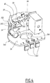
- the box 4 forms an internal volume V in which are integrated electrical supply members of the luminaire, connection members between the connection socket 10 of the luminaire and the connection zone 12 to the electrical network, and a control and monitoring system. communication with a device external to the connection device 2.
- the device 2 centralizes, in the same box 4, functions for adapting and regulating the power supply 20, a microprocessor 22 implementing operating software (" firmware ”) and a communication module, colored diodes 24 indicating operating states of the device, a button 26 for controlling the device 2 and for implementing certain functions, in particular pairing with an external electronic device, and a relay 28, 342 for switching on the luminaire.
- the connection device 2 is supplied with mains electricity via the connection zone 12.
- the diodes 24, the button 26 and the relay 28, 342 are electrically connected to the microprocessor 22.
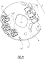
- the control and communication system is provided on an electronic card 30 visible at the figure 6 and mounted in the box 4.
- This card 30 comprises in particular the microprocessor 22, two diodes 24 and the push button 26.
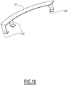
- the control and communication system comprises a radio-frequency communication antenna 32 connected to the card 30.
- the antenna 32 In order to allow the transmission and reception of waves, for example of Bluetooth or Zigbee technology, the antenna 32 must be located outside the volume of the mounting space 6 so that the material of the wall 8, for example concrete, does not prevent the propagation of waves.
- the front face 14, integral with the housing 4 is therefore configured to protrude outside the mounting space 6, and the antenna 32 is provided in a zone of the device 2 located in a volume V14 delimited by the front face 14.
- the antenna 32 is located beyond an external face 80 of the wall 8.
- the antenna 32 comprises feet 320 fixed on the card 30, and which allow an elevation of the antenna 32 relative to the card 30.
- the front face 14 has a wall provided with a reduction in thickness 14a forming a cavity 14b oriented on an internal side of the housing 4 and in which the communication antenna 32 is received. This reduction in thickness allows an improvement in the reception and emission of waves by the antenna 32.
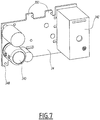
- the electrical power supply members of the electronic device and of the luminaire are provided on an electronic card 34 mounted in the box 4. These members are configured to provide and regulate the direct current supply from the received alternating current mains supply. by the device 2.
- On this card 34 are in particular installed a filter capacitor 340 and a relay 342.
- connection members between the connection socket 10 of the luminaire and the connection zone 12 to the electrical network are provided on an electronic card 36 mounted in the box 4.
- This card 36 comprises in particular three connection terminals 360 (phase, neutral, ground ) forming the connection socket 10 to the luminaire, and three connection terminals 362 (phase, neutral, earth) forming the connection zone 12 to the electrical network.
- the electronic card 34 is oriented parallel to the central axis X4, and the cards 30 and 36 are oriented perpendicular to the central axis X4.
- the card 30 is fixed on a first axial edge 344 of the card 34, located on the side of the front face 14, and the card 36 is fixed on a second axial edge 346 of the card 34, opposite to the first axial edge 344 according to l 'central axis X4, that is to say on the side of the rear face 16.
- the control and communication components in particular the button 26 and the antenna 32, are located near the front face 14, of so as to protrude outside the wall 8, while the connection terminals 362 are on the rear face 16 so as to be able to be connected to electric wires present in the assembly space 6.
- the electronic cards 30 and 36 have a respective external contour 300 and 364 semi-circular centered on the central axis X4 and delimited by an internal wall 40 of the box 4, and a respective central orifice 302 and 366 extending around the central duct 18 of the box 4.
- the electronic cards 30, 34 and 36 are fixed to each other by embedding members and welds ensuring the electrical connection between the cards.
- the card 34 comprises two fixing and connection tabs 348 (phase and neutral) to the card 36. These two tabs 348 are received in two complementary holes 368 provided on the card 36.
- the tabs 348 are provided with tracks conductors, not shown, which provide electrical contact with conductive tracks, not shown, provided on the periphery of the orifices 368. Welds, not shown, ensure the mechanical strength of the assembly of the tabs 348 and the orifices 368 as well as electrical conduction.
- the card 34 also comprises two fixing and connection lugs 350 (phase and neutral), which are received in two complementary holes 304 of the card 30.
- Conductive tracks and welds, not shown, ensure the mechanical strength of the. assembly of tabs 350 and orifices 304 and electrical conduction.
- the box 4 can include two assembled parts 4A and 4B.
- the part 4A is cylindrical in shape and carries the front face 14.
- the assembly formed by the three cards 30, 34 and 36 is inserted into the part 4A.
- the part 4B carries the rear face 16 and closes the interior volume V of the box 4 and encapsulates the cards 30, 34 and 36 in the box 4.
Landscapes
- Engineering & Computer Science (AREA)
- General Engineering & Computer Science (AREA)
- Computer Networks & Wireless Communication (AREA)
- Microelectronics & Electronic Packaging (AREA)
- Architecture (AREA)
- Civil Engineering (AREA)
- Structural Engineering (AREA)
- Arrangement Of Elements, Cooling, Sealing, Or The Like Of Lighting Devices (AREA)
- Support Of Aerials (AREA)
- Coupling Device And Connection With Printed Circuit (AREA)
Claims (5)
- Anschlussvorrichtung (2) für eine Leuchte, mit einem Gehäuse (4), das vorgesehen ist, in einem Einbauraum (6) in einer Wand (8) eines Raumes installiert zu werden, wobei diese Vorrichtung (2) eine Anschlussbuchse (10) einer Leuchte und einen Bereich (12) für den Anschluss an ein elektrisches Netz umfasst, wobei das Gehäuse (4) ein Innenvolumen (V) bildet, in das elektrische Versorgungselemente der Leuchte, Verbindungselemente zwischen der Anschlussbuchse (10) der Leuchte und dem Bereich (12) für den Anschluss an das elektrische Netz und ein System zur Steuerung und Kommunikation mit einem Gerät außerhalb der Anschlussvorrichtung (2) integriert sind, wobei diese Vorrichtung dadurch gekennzeichnet ist, dass das Steuer- und Kommunikationssystem eine Hochfrequenz-Kommunikationsantenne (32) umfasst, dass die Vorrichtung (2) eine mit dem Gehäuse (4) fest verbundene Vorderseite (14) aufweist, die ausgebildet ist, aus dem Montageraum (6) herauszuragen, wobei die Antenne (32) in einem Bereich der Vorrichtung (2) vorgesehen ist, der sich in einem von der Vorderseite (14) begrenzten Volumen (V14) befindet, und dass die Vorderseite (14) eine mit einer Dickenverringerung (14a) versehene Wand aufweist, die einen Hohlraum (14b) bildet, der zu einer Innenseite des Gehäuses (4) hin ausgerichtet ist und in dem die Kommunikationsantenne (32) aufgenommen ist.
- Anschlussvorrichtung nach Anspruch 1, dadurch gekennzeichnet, dass die elektrischen Versorgungselemente der Leuchte auf einer ersten, im Gehäuse (4) montierten Elektronikplatine (34) vorgesehen sind, dass die Verbindungselemente zwischen der Anschlussdose (10) der Leuchte und dem Bereich (12) für den Anschluss an das elektrische Netz auf einer zweiten, im Gehäuse (4) montierten Elektronikplatine (36) vorgesehen sind, und dass das Steuer- und Kommunikationssystem auf einer dritten, im Gehäuse (4) montierten Elektronikplatine (30) vorgesehen ist.
- Anschlussvorrichtung nach Anspruch 2, dadurch gekennzeichnet, dass die erste Elektronikplatine (34) parallel zu einer Mittelachse (X4) des Gehäuses (4) ausgerichtet ist und dass die zweite und die dritte Platine (36, 30) senkrecht zur Mittelachse (X4) ausgerichtet sind, wobei die zweite Platine (36) an einem ersten axialen Rand (346) der ersten Platine (34) und die dritte Platine (30) an einem zweiten axialen Rand (344) der ersten Platine (34) entgegengesetzt zu dem ersten axialen Rand (346) entlang der Mittelachse (X4) befestigt ist.
- Anschlussvorrichtung nach Anspruch 3, dadurch gekennzeichnet, dass die Elektronikplatinen (30, 34, 36) durch Einsteckelemente (348, 350, 368, 304) und Lötstellen, die die elektrische Verbindung zwischen den Karten sicherstellen, befestigt sind.
- Anschlussvorrichtung nach einem der Ansprüche 3 und 4, dadurch gekennzeichnet, dass die zweite (36) und die dritte (30) Elektronikplatine eine halbkreisförmige Außenkontur (364, 300), die auf die Mittelachse (X4) zentriert und durch eine Innenwand (40) des Gehäuses (4) begrenzt ist, und eine zentrale Öffnung (366, 302), die sich um einen zentralen Kanal (18) des Gehäuses (4) herum erstreckt, aufweisen.
Applications Claiming Priority (1)
| Application Number | Priority Date | Filing Date | Title |
|---|---|---|---|
| FR1873226A FR3090224B1 (fr) | 2018-12-18 | 2018-12-18 | Dispositif de connexion pour un luminaire |
Publications (2)
| Publication Number | Publication Date |
|---|---|
| EP3671030A1 EP3671030A1 (de) | 2020-06-24 |
| EP3671030B1 true EP3671030B1 (de) | 2021-06-30 |
Family
ID=66530244
Family Applications (1)
| Application Number | Title | Priority Date | Filing Date |
|---|---|---|---|
| EP19217643.6A Active EP3671030B1 (de) | 2018-12-18 | 2019-12-18 | Verbindungsvorrichtung für einen beleuchtungskörper |
Country Status (6)
| Country | Link |
|---|---|
| US (1) | US11029012B2 (de) |
| EP (1) | EP3671030B1 (de) |
| CN (1) | CN111336479B (de) |
| AU (1) | AU2019283762B2 (de) |
| ES (1) | ES2887952T3 (de) |
| FR (1) | FR3090224B1 (de) |
Families Citing this family (1)
| Publication number | Priority date | Publication date | Assignee | Title |
|---|---|---|---|---|
| FR3090224B1 (fr) * | 2018-12-18 | 2021-03-12 | Schneider Electric Ind Sas | Dispositif de connexion pour un luminaire |
Family Cites Families (35)
| Publication number | Priority date | Publication date | Assignee | Title |
|---|---|---|---|---|
| US7888597B2 (en) * | 2008-10-02 | 2011-02-15 | Aslan Industries Corporation | Fixture box enclosure |
| DE102009022401A1 (de) * | 2009-01-21 | 2010-07-22 | Abb Ag | Leuchte, insbesondere Wandleuchte |
| US9039271B2 (en) * | 2010-03-24 | 2015-05-26 | Cree, Inc. | Interface and fabrication method for lighting and other electrical devices |
| EP2567430B2 (de) * | 2010-05-06 | 2022-02-23 | TESGL Limited | Verbesserungen an und in zusammenhang mit elektrischen verbindern |
| US8398435B2 (en) * | 2011-05-05 | 2013-03-19 | General Electric Company | Receptacle connector between controller and lighting fixture |
| US8864514B2 (en) * | 2010-10-07 | 2014-10-21 | General Electric Company | Controller device |
| US9882361B2 (en) * | 2011-08-01 | 2018-01-30 | Snaprays Llc | Active cover plates |
| US9366418B2 (en) * | 2011-09-30 | 2016-06-14 | Graham GIFFORD | Method, apparatus and system for connecting a light emitting diode light fixture to a mains power conductor |
| SG195090A1 (en) * | 2012-10-22 | 2013-12-30 | Aztech Technologies Pte Ltd | An led lighting device having elastically biased end caps |
| KR101999660B1 (ko) * | 2012-11-08 | 2019-10-01 | 엘지이노텍 주식회사 | 통신 모듈을 포함하는 조명 장치 |
| US11221110B2 (en) * | 2013-03-13 | 2022-01-11 | Smartbotics, Inc. | LED light bulb construction and manufacture |
| US9062837B2 (en) * | 2013-04-05 | 2015-06-23 | Cooper Technologies Company | Housings and related components for luminaires |
| JP6235698B2 (ja) * | 2013-04-23 | 2017-11-22 | フィリップス ライティング ホールディング ビー ヴィ | アンテナを含む照明デバイス及び照明器具 |
| US10753558B2 (en) * | 2013-07-05 | 2020-08-25 | DMF, Inc. | Lighting apparatus and methods |
| DE202013007161U1 (de) * | 2013-08-12 | 2013-10-10 | Abb Ag | Elektrisches Installationsgerät mit Beleuchtungselement |
| US20150087174A1 (en) * | 2013-09-25 | 2015-03-26 | Osram Sylvania Inc. | Mountable connector box for electrical device |
| AU2015202768B2 (en) * | 2014-05-22 | 2019-02-07 | Gooee Limited | Sensor Arrangements |
| US9447953B2 (en) * | 2014-05-30 | 2016-09-20 | Generation Brands Llc | Adjustable luminaire |
| US9729791B2 (en) * | 2014-10-31 | 2017-08-08 | Ubiquiti Networks, Inc. | Micro camera and multi-purpose mounting base |
| SG10201501166SA (en) * | 2015-02-13 | 2016-09-29 | Xin Yu Sg Pte Ltd | A Communications Device |
| US20180017243A1 (en) * | 2015-01-26 | 2018-01-18 | Energyficient Lighting Syst. | Unitary Led Lighting Assembly With O-Ring and Related Systems and Methods |
| MX373411B (es) * | 2015-01-26 | 2020-05-27 | Energyficient Lighting Systems Inc | Ensamble de iluminacion led modular y sistemas y metodos relacionados. |
| AU2016262102B2 (en) * | 2015-05-12 | 2021-07-08 | Skyx Platforms Corp. | Smart quick connect device for electrical fixtures |
| US10302292B2 (en) * | 2016-01-07 | 2019-05-28 | Michael W. May | Connector system for lighting assembly |
| US10733944B2 (en) * | 2016-02-19 | 2020-08-04 | Signify Holding B.V. | Configurable modes for lighting systems |
| US10290265B2 (en) * | 2016-02-19 | 2019-05-14 | Eaton Intelligent Power Limited | Configurable modes for lighting systems |
| US10330268B2 (en) * | 2016-04-25 | 2019-06-25 | Epistar Corporation | SSL retrofit fixture |
| GB2568415B (en) * | 2017-02-16 | 2020-04-01 | Aurora Ltd | A sensor arrangement for a luminaire assembly |
| US10422494B2 (en) * | 2017-05-03 | 2019-09-24 | Eaton Intelligent Power Limited | High mast luminaire |
| US9970634B1 (en) * | 2017-05-04 | 2018-05-15 | Cooper Technologies Company | Recessed luminaire for remodel applications |
| US11175002B2 (en) * | 2017-06-23 | 2021-11-16 | Nulite Lighting | LED driver box |
| US10330279B2 (en) * | 2017-08-01 | 2019-06-25 | Kenall Manufacturing Company | Luminaire with rear-mounted sensing assembly |
| WO2019133669A1 (en) * | 2017-12-27 | 2019-07-04 | DMF, Inc. | Methods and apparatus for adjusting a luminaire |
| US10571099B2 (en) * | 2018-04-20 | 2020-02-25 | Eaton Intelligent Power Limited | Surface mount luminaire |
| FR3090224B1 (fr) * | 2018-12-18 | 2021-03-12 | Schneider Electric Ind Sas | Dispositif de connexion pour un luminaire |
-
2018
- 2018-12-18 FR FR1873226A patent/FR3090224B1/fr not_active Expired - Fee Related
-
2019
- 2019-12-03 US US16/701,273 patent/US11029012B2/en active Active
- 2019-12-16 AU AU2019283762A patent/AU2019283762B2/en active Active
- 2019-12-18 EP EP19217643.6A patent/EP3671030B1/de active Active
- 2019-12-18 CN CN201911307104.6A patent/CN111336479B/zh active Active
- 2019-12-18 ES ES19217643T patent/ES2887952T3/es active Active
Also Published As
| Publication number | Publication date |
|---|---|
| RU2019141073A (ru) | 2021-06-15 |
| FR3090224A1 (fr) | 2020-06-19 |
| AU2019283762B2 (en) | 2025-07-03 |
| FR3090224B1 (fr) | 2021-03-12 |
| AU2019283762A1 (en) | 2020-07-02 |
| US20200191372A1 (en) | 2020-06-18 |
| CN111336479A (zh) | 2020-06-26 |
| US11029012B2 (en) | 2021-06-08 |
| EP3671030A1 (de) | 2020-06-24 |
| CN111336479B (zh) | 2023-05-05 |
| ES2887952T3 (es) | 2021-12-29 |
Similar Documents
| Publication | Publication Date | Title |
|---|---|---|
| EP3325875B1 (de) | Anschluss für elektrogeräte | |
| EP2936638A1 (de) | Elektrisches gehäuse für eine elektrische vorrichtung | |
| EP3671030B1 (de) | Verbindungsvorrichtung für einen beleuchtungskörper | |
| FR2956526A1 (fr) | Systeme de connexion electrique comprenant une prise murale et une prise mobile destinee a etre reliee a un equipement electrique et prevue pour cooperer avec ladite prise murale | |
| EP0464451A1 (de) | Verstellbarer elektrischer Verbinder, zur Installation zwischen ein elektrisches Verbrauchergerät und einer Wandsteckdose | |
| FR3097083A1 (fr) | Boîtier électrique pour luminaire de plafond | |
| EP3836315A1 (de) | Steckdose | |
| FR2698729A1 (fr) | Dispositif de connexion électrique d'une pluralité de câbles. | |
| EP2951899B1 (de) | Zweiteiliger installationskasten | |
| EP3651278B1 (de) | Steckdose mit leuchtquelle | |
| FR2731397A1 (fr) | Installation d'alimentation electrique pour caravane ou similaire | |
| FR2970539A1 (fr) | Module individuel pour collecteur de circuit d'eau de plancher chauffant | |
| FR2958087A1 (fr) | Dispositif de connexion pour recevoir une information provenant d'une ligne electrique integree dans une cloison un support ou pour emettre une information sur la ligne electrique | |
| EP1077351A1 (de) | Elektrisches Steuergerät für einen Heizkörper, insbesondere einen elektrischen Handtuchtrockner | |
| FR3066856A1 (fr) | Mecanisme d’appareillage electrique et appareillage electrique comprenant un tel mecanisme | |
| EP2924825B1 (de) | Produkt mit akustischer Lokalisierungsvorrichtung für elektrische Anlage, die ein Netz und mindestens eine Geräteausstattung umfasst, und entsprechende Anlage, die zusätzlich mindestens ein solches Produkt umfasst | |
| FR2794905A1 (fr) | Dispositif destine a s'inserer, simplement et rapidement, dans un systeme d'eclairage, entre la douille et la lampe, pour le controle de cette derniere | |
| EP1002345B1 (de) | Elektrische verbindungsdose | |
| FR2524652A1 (fr) | Recepteur de rayonnement, optique susceptible d'etre associee a un tel recepteur, et montage correspondant | |
| FR2803119A1 (fr) | Dispositif encastrable permettant d'augmenter le rayon d'action d'une installation electrique mobile | |
| FR2613544A1 (fr) | Dispositif pour prise electrique murale | |
| FR2760907A1 (fr) | Chemin de cable de faux-plafond ou de plancher technique | |
| EP1130685A2 (de) | Zusatzeinrichtung zur Bereitstellung von Platz für zeitweiliges Verbinden | |
| FR3051289A1 (fr) | Appareillage electrique equipe de systemes de fixation a griffes | |
| FR3103641A1 (fr) | Équipement électrique à pièce de bridage anti-translation |
Legal Events
| Date | Code | Title | Description |
|---|---|---|---|
| PUAI | Public reference made under article 153(3) epc to a published international application that has entered the european phase |
Free format text: ORIGINAL CODE: 0009012 |
|
| STAA | Information on the status of an ep patent application or granted ep patent |
Free format text: STATUS: THE APPLICATION HAS BEEN PUBLISHED |
|
| AK | Designated contracting states |
Kind code of ref document: A1 Designated state(s): AL AT BE BG CH CY CZ DE DK EE ES FI FR GB GR HR HU IE IS IT LI LT LU LV MC MK MT NL NO PL PT RO RS SE SI SK SM TR |
|
| AX | Request for extension of the european patent |
Extension state: BA ME |
|
| STAA | Information on the status of an ep patent application or granted ep patent |
Free format text: STATUS: REQUEST FOR EXAMINATION WAS MADE |
|
| 17P | Request for examination filed |
Effective date: 20201127 |
|
| RBV | Designated contracting states (corrected) |
Designated state(s): AL AT BE BG CH CY CZ DE DK EE ES FI FR GB GR HR HU IE IS IT LI LT LU LV MC MK MT NL NO PL PT RO RS SE SI SK SM TR |
|
| GRAP | Despatch of communication of intention to grant a patent |
Free format text: ORIGINAL CODE: EPIDOSNIGR1 |
|
| STAA | Information on the status of an ep patent application or granted ep patent |
Free format text: STATUS: GRANT OF PATENT IS INTENDED |
|
| RIC1 | Information provided on ipc code assigned before grant |
Ipc: F21V 21/03 20060101AFI20210129BHEP Ipc: H02G 3/08 20060101ALI20210129BHEP Ipc: F21V 23/04 20060101ALI20210129BHEP Ipc: H02G 3/20 20060101ALI20210129BHEP |
|
| INTG | Intention to grant announced |
Effective date: 20210304 |
|
| RIN1 | Information on inventor provided before grant (corrected) |
Inventor name: PETTINOTTO, GILLES Inventor name: JONSSON, MICHAEL Inventor name: DALBE, MICHEL |
|
| GRAS | Grant fee paid |
Free format text: ORIGINAL CODE: EPIDOSNIGR3 |
|
| GRAA | (expected) grant |
Free format text: ORIGINAL CODE: 0009210 |
|
| STAA | Information on the status of an ep patent application or granted ep patent |
Free format text: STATUS: THE PATENT HAS BEEN GRANTED |
|
| AK | Designated contracting states |
Kind code of ref document: B1 Designated state(s): AL AT BE BG CH CY CZ DE DK EE ES FI FR GB GR HR HU IE IS IT LI LT LU LV MC MK MT NL NO PL PT RO RS SE SI SK SM TR |
|
| REG | Reference to a national code |
Ref country code: CH Ref legal event code: EP |
|
| REG | Reference to a national code |
Ref country code: AT Ref legal event code: REF Ref document number: 1406661 Country of ref document: AT Kind code of ref document: T Effective date: 20210715 |
|
| REG | Reference to a national code |
Ref country code: DE Ref legal event code: R096 Ref document number: 602019005772 Country of ref document: DE |
|
| REG | Reference to a national code |
Ref country code: IE Ref legal event code: FG4D Free format text: LANGUAGE OF EP DOCUMENT: FRENCH |
|
| REG | Reference to a national code |
Ref country code: LT Ref legal event code: MG9D |
|
| PG25 | Lapsed in a contracting state [announced via postgrant information from national office to epo] |
Ref country code: BG Free format text: LAPSE BECAUSE OF FAILURE TO SUBMIT A TRANSLATION OF THE DESCRIPTION OR TO PAY THE FEE WITHIN THE PRESCRIBED TIME-LIMIT Effective date: 20210930 Ref country code: HR Free format text: LAPSE BECAUSE OF FAILURE TO SUBMIT A TRANSLATION OF THE DESCRIPTION OR TO PAY THE FEE WITHIN THE PRESCRIBED TIME-LIMIT Effective date: 20210630 Ref country code: FI Free format text: LAPSE BECAUSE OF FAILURE TO SUBMIT A TRANSLATION OF THE DESCRIPTION OR TO PAY THE FEE WITHIN THE PRESCRIBED TIME-LIMIT Effective date: 20210630 |
|
| REG | Reference to a national code |
Ref country code: NL Ref legal event code: MP Effective date: 20210630 |
|
| REG | Reference to a national code |
Ref country code: AT Ref legal event code: MK05 Ref document number: 1406661 Country of ref document: AT Kind code of ref document: T Effective date: 20210630 |
|
| PG25 | Lapsed in a contracting state [announced via postgrant information from national office to epo] |
Ref country code: GR Free format text: LAPSE BECAUSE OF FAILURE TO SUBMIT A TRANSLATION OF THE DESCRIPTION OR TO PAY THE FEE WITHIN THE PRESCRIBED TIME-LIMIT Effective date: 20211001 Ref country code: NO Free format text: LAPSE BECAUSE OF FAILURE TO SUBMIT A TRANSLATION OF THE DESCRIPTION OR TO PAY THE FEE WITHIN THE PRESCRIBED TIME-LIMIT Effective date: 20210930 Ref country code: LV Free format text: LAPSE BECAUSE OF FAILURE TO SUBMIT A TRANSLATION OF THE DESCRIPTION OR TO PAY THE FEE WITHIN THE PRESCRIBED TIME-LIMIT Effective date: 20210630 Ref country code: SE Free format text: LAPSE BECAUSE OF FAILURE TO SUBMIT A TRANSLATION OF THE DESCRIPTION OR TO PAY THE FEE WITHIN THE PRESCRIBED TIME-LIMIT Effective date: 20210630 Ref country code: RS Free format text: LAPSE BECAUSE OF FAILURE TO SUBMIT A TRANSLATION OF THE DESCRIPTION OR TO PAY THE FEE WITHIN THE PRESCRIBED TIME-LIMIT Effective date: 20210630 |
|
| REG | Reference to a national code |
Ref country code: ES Ref legal event code: FG2A Ref document number: 2887952 Country of ref document: ES Kind code of ref document: T3 Effective date: 20211229 |
|
| PG25 | Lapsed in a contracting state [announced via postgrant information from national office to epo] |
Ref country code: SK Free format text: LAPSE BECAUSE OF FAILURE TO SUBMIT A TRANSLATION OF THE DESCRIPTION OR TO PAY THE FEE WITHIN THE PRESCRIBED TIME-LIMIT Effective date: 20210630 Ref country code: EE Free format text: LAPSE BECAUSE OF FAILURE TO SUBMIT A TRANSLATION OF THE DESCRIPTION OR TO PAY THE FEE WITHIN THE PRESCRIBED TIME-LIMIT Effective date: 20210630 Ref country code: RO Free format text: LAPSE BECAUSE OF FAILURE TO SUBMIT A TRANSLATION OF THE DESCRIPTION OR TO PAY THE FEE WITHIN THE PRESCRIBED TIME-LIMIT Effective date: 20210630 Ref country code: NL Free format text: LAPSE BECAUSE OF FAILURE TO SUBMIT A TRANSLATION OF THE DESCRIPTION OR TO PAY THE FEE WITHIN THE PRESCRIBED TIME-LIMIT Effective date: 20210630 Ref country code: PT Free format text: LAPSE BECAUSE OF FAILURE TO SUBMIT A TRANSLATION OF THE DESCRIPTION OR TO PAY THE FEE WITHIN THE PRESCRIBED TIME-LIMIT Effective date: 20211102 Ref country code: SM Free format text: LAPSE BECAUSE OF FAILURE TO SUBMIT A TRANSLATION OF THE DESCRIPTION OR TO PAY THE FEE WITHIN THE PRESCRIBED TIME-LIMIT Effective date: 20210630 Ref country code: CZ Free format text: LAPSE BECAUSE OF FAILURE TO SUBMIT A TRANSLATION OF THE DESCRIPTION OR TO PAY THE FEE WITHIN THE PRESCRIBED TIME-LIMIT Effective date: 20210630 Ref country code: AT Free format text: LAPSE BECAUSE OF FAILURE TO SUBMIT A TRANSLATION OF THE DESCRIPTION OR TO PAY THE FEE WITHIN THE PRESCRIBED TIME-LIMIT Effective date: 20210630 |
|
| PG25 | Lapsed in a contracting state [announced via postgrant information from national office to epo] |
Ref country code: PL Free format text: LAPSE BECAUSE OF FAILURE TO SUBMIT A TRANSLATION OF THE DESCRIPTION OR TO PAY THE FEE WITHIN THE PRESCRIBED TIME-LIMIT Effective date: 20210630 |
|
| REG | Reference to a national code |
Ref country code: DE Ref legal event code: R097 Ref document number: 602019005772 Country of ref document: DE |
|
| PG25 | Lapsed in a contracting state [announced via postgrant information from national office to epo] |
Ref country code: DK Free format text: LAPSE BECAUSE OF FAILURE TO SUBMIT A TRANSLATION OF THE DESCRIPTION OR TO PAY THE FEE WITHIN THE PRESCRIBED TIME-LIMIT Effective date: 20210630 |
|
| PLBE | No opposition filed within time limit |
Free format text: ORIGINAL CODE: 0009261 |
|
| STAA | Information on the status of an ep patent application or granted ep patent |
Free format text: STATUS: NO OPPOSITION FILED WITHIN TIME LIMIT |
|
| PG25 | Lapsed in a contracting state [announced via postgrant information from national office to epo] |
Ref country code: AL Free format text: LAPSE BECAUSE OF FAILURE TO SUBMIT A TRANSLATION OF THE DESCRIPTION OR TO PAY THE FEE WITHIN THE PRESCRIBED TIME-LIMIT Effective date: 20210630 |
|
| 26N | No opposition filed |
Effective date: 20220331 |
|
| PG25 | Lapsed in a contracting state [announced via postgrant information from national office to epo] |
Ref country code: MC Free format text: LAPSE BECAUSE OF FAILURE TO SUBMIT A TRANSLATION OF THE DESCRIPTION OR TO PAY THE FEE WITHIN THE PRESCRIBED TIME-LIMIT Effective date: 20210630 |
|
| REG | Reference to a national code |
Ref country code: BE Ref legal event code: MM Effective date: 20211231 |
|
| PG25 | Lapsed in a contracting state [announced via postgrant information from national office to epo] |
Ref country code: LU Free format text: LAPSE BECAUSE OF NON-PAYMENT OF DUE FEES Effective date: 20211218 Ref country code: IE Free format text: LAPSE BECAUSE OF NON-PAYMENT OF DUE FEES Effective date: 20211218 |
|
| PG25 | Lapsed in a contracting state [announced via postgrant information from national office to epo] |
Ref country code: BE Free format text: LAPSE BECAUSE OF NON-PAYMENT OF DUE FEES Effective date: 20211231 |
|
| PG25 | Lapsed in a contracting state [announced via postgrant information from national office to epo] |
Ref country code: LT Free format text: LAPSE BECAUSE OF FAILURE TO SUBMIT A TRANSLATION OF THE DESCRIPTION OR TO PAY THE FEE WITHIN THE PRESCRIBED TIME-LIMIT Effective date: 20210630 |
|
| PG25 | Lapsed in a contracting state [announced via postgrant information from national office to epo] |
Ref country code: CY Free format text: LAPSE BECAUSE OF FAILURE TO SUBMIT A TRANSLATION OF THE DESCRIPTION OR TO PAY THE FEE WITHIN THE PRESCRIBED TIME-LIMIT Effective date: 20210630 |
|
| PG25 | Lapsed in a contracting state [announced via postgrant information from national office to epo] |
Ref country code: HU Free format text: LAPSE BECAUSE OF FAILURE TO SUBMIT A TRANSLATION OF THE DESCRIPTION OR TO PAY THE FEE WITHIN THE PRESCRIBED TIME-LIMIT; INVALID AB INITIO Effective date: 20191218 |
|
| REG | Reference to a national code |
Ref country code: CH Ref legal event code: PL |
|
| PG25 | Lapsed in a contracting state [announced via postgrant information from national office to epo] |
Ref country code: LI Free format text: LAPSE BECAUSE OF NON-PAYMENT OF DUE FEES Effective date: 20221231 Ref country code: CH Free format text: LAPSE BECAUSE OF NON-PAYMENT OF DUE FEES Effective date: 20221231 |
|
| PG25 | Lapsed in a contracting state [announced via postgrant information from national office to epo] |
Ref country code: MK Free format text: LAPSE BECAUSE OF FAILURE TO SUBMIT A TRANSLATION OF THE DESCRIPTION OR TO PAY THE FEE WITHIN THE PRESCRIBED TIME-LIMIT Effective date: 20210630 |
|
| GBPC | Gb: european patent ceased through non-payment of renewal fee |
Effective date: 20231218 |
|
| PG25 | Lapsed in a contracting state [announced via postgrant information from national office to epo] |
Ref country code: MT Free format text: LAPSE BECAUSE OF FAILURE TO SUBMIT A TRANSLATION OF THE DESCRIPTION OR TO PAY THE FEE WITHIN THE PRESCRIBED TIME-LIMIT Effective date: 20210630 |
|
| PG25 | Lapsed in a contracting state [announced via postgrant information from national office to epo] |
Ref country code: GB Free format text: LAPSE BECAUSE OF NON-PAYMENT OF DUE FEES Effective date: 20231218 |
|
| PG25 | Lapsed in a contracting state [announced via postgrant information from national office to epo] |
Ref country code: GB Free format text: LAPSE BECAUSE OF NON-PAYMENT OF DUE FEES Effective date: 20231218 |
|
| PGFP | Annual fee paid to national office [announced via postgrant information from national office to epo] |
Ref country code: IT Payment date: 20241220 Year of fee payment: 6 |
|
| PGFP | Annual fee paid to national office [announced via postgrant information from national office to epo] |
Ref country code: ES Payment date: 20250113 Year of fee payment: 6 |
|
| PG25 | Lapsed in a contracting state [announced via postgrant information from national office to epo] |
Ref country code: TR Free format text: LAPSE BECAUSE OF FAILURE TO SUBMIT A TRANSLATION OF THE DESCRIPTION OR TO PAY THE FEE WITHIN THE PRESCRIBED TIME-LIMIT Effective date: 20210630 |
|
| PGFP | Annual fee paid to national office [announced via postgrant information from national office to epo] |
Ref country code: FR Payment date: 20251230 Year of fee payment: 7 |
|
| PGFP | Annual fee paid to national office [announced via postgrant information from national office to epo] |
Ref country code: DE Payment date: 20251229 Year of fee payment: 7 |