EP3671034B1 - Lampe réglable - Google Patents
Lampe réglable Download PDFInfo
- Publication number
- EP3671034B1 EP3671034B1 EP19216880.5A EP19216880A EP3671034B1 EP 3671034 B1 EP3671034 B1 EP 3671034B1 EP 19216880 A EP19216880 A EP 19216880A EP 3671034 B1 EP3671034 B1 EP 3671034B1
- Authority
- EP
- European Patent Office
- Prior art keywords
- distance
- light sources
- distance meter
- luminosity
- light source
- Prior art date
- Legal status (The legal status is an assumption and is not a legal conclusion. Google has not performed a legal analysis and makes no representation as to the accuracy of the status listed.)
- Active
Links
Images

Classifications
-
- F—MECHANICAL ENGINEERING; LIGHTING; HEATING; WEAPONS; BLASTING
- F21—LIGHTING
- F21V—FUNCTIONAL FEATURES OR DETAILS OF LIGHTING DEVICES OR SYSTEMS THEREOF; STRUCTURAL COMBINATIONS OF LIGHTING DEVICES WITH OTHER ARTICLES, NOT OTHERWISE PROVIDED FOR
- F21V23/00—Arrangement of electric circuit elements in or on lighting devices
- F21V23/04—Arrangement of electric circuit elements in or on lighting devices the elements being switches
- F21V23/0442—Arrangement of electric circuit elements in or on lighting devices the elements being switches activated by means of a sensor, e.g. motion or photodetectors
- F21V23/0471—Arrangement of electric circuit elements in or on lighting devices the elements being switches activated by means of a sensor, e.g. motion or photodetectors the sensor detecting the proximity, the presence or the movement of an object or a person
-
- F—MECHANICAL ENGINEERING; LIGHTING; HEATING; WEAPONS; BLASTING
- F21—LIGHTING
- F21L—LIGHTING DEVICES OR SYSTEMS THEREOF, BEING PORTABLE OR SPECIALLY ADAPTED FOR TRANSPORTATION
- F21L4/00—Electric lighting devices with self-contained electric batteries or cells
- F21L4/005—Electric lighting devices with self-contained electric batteries or cells the device being a pocket lamp
-
- F—MECHANICAL ENGINEERING; LIGHTING; HEATING; WEAPONS; BLASTING
- F21—LIGHTING
- F21V—FUNCTIONAL FEATURES OR DETAILS OF LIGHTING DEVICES OR SYSTEMS THEREOF; STRUCTURAL COMBINATIONS OF LIGHTING DEVICES WITH OTHER ARTICLES, NOT OTHERWISE PROVIDED FOR
- F21V23/00—Arrangement of electric circuit elements in or on lighting devices
- F21V23/04—Arrangement of electric circuit elements in or on lighting devices the elements being switches
- F21V23/0414—Arrangement of electric circuit elements in or on lighting devices the elements being switches specially adapted to be used with portable lighting devices
-
- H—ELECTRICITY
- H05—ELECTRIC TECHNIQUES NOT OTHERWISE PROVIDED FOR
- H05B—ELECTRIC HEATING; ELECTRIC LIGHT SOURCES NOT OTHERWISE PROVIDED FOR; CIRCUIT ARRANGEMENTS FOR ELECTRIC LIGHT SOURCES, IN GENERAL
- H05B45/00—Circuit arrangements for operating light-emitting diodes [LED]
- H05B45/10—Controlling the intensity of the light
-
- H—ELECTRICITY
- H05—ELECTRIC TECHNIQUES NOT OTHERWISE PROVIDED FOR
- H05B—ELECTRIC HEATING; ELECTRIC LIGHT SOURCES NOT OTHERWISE PROVIDED FOR; CIRCUIT ARRANGEMENTS FOR ELECTRIC LIGHT SOURCES, IN GENERAL
- H05B45/00—Circuit arrangements for operating light-emitting diodes [LED]
- H05B45/10—Controlling the intensity of the light
- H05B45/18—Controlling the intensity of the light using temperature feedback
-
- H—ELECTRICITY
- H05—ELECTRIC TECHNIQUES NOT OTHERWISE PROVIDED FOR
- H05B—ELECTRIC HEATING; ELECTRIC LIGHT SOURCES NOT OTHERWISE PROVIDED FOR; CIRCUIT ARRANGEMENTS FOR ELECTRIC LIGHT SOURCES, IN GENERAL
- H05B47/00—Circuit arrangements for operating light sources in general, i.e. where the type of light source is not relevant
- H05B47/10—Controlling the light source
- H05B47/105—Controlling the light source in response to determined parameters
- H05B47/115—Controlling the light source in response to determined parameters by determining the presence or movement of objects or living beings
-
- F—MECHANICAL ENGINEERING; LIGHTING; HEATING; WEAPONS; BLASTING
- F21—LIGHTING
- F21Y—INDEXING SCHEME ASSOCIATED WITH SUBCLASSES F21K, F21L, F21S and F21V, RELATING TO THE FORM OR THE KIND OF THE LIGHT SOURCES OR OF THE COLOUR OF THE LIGHT EMITTED
- F21Y2115/00—Light-generating elements of semiconductor light sources
- F21Y2115/10—Light-emitting diodes [LED]
-
- Y—GENERAL TAGGING OF NEW TECHNOLOGICAL DEVELOPMENTS; GENERAL TAGGING OF CROSS-SECTIONAL TECHNOLOGIES SPANNING OVER SEVERAL SECTIONS OF THE IPC; TECHNICAL SUBJECTS COVERED BY FORMER USPC CROSS-REFERENCE ART COLLECTIONS [XRACs] AND DIGESTS
- Y02—TECHNOLOGIES OR APPLICATIONS FOR MITIGATION OR ADAPTATION AGAINST CLIMATE CHANGE
- Y02B—CLIMATE CHANGE MITIGATION TECHNOLOGIES RELATED TO BUILDINGS, e.g. HOUSING, HOUSE APPLIANCES OR RELATED END-USER APPLICATIONS
- Y02B20/00—Energy efficient lighting technologies, e.g. halogen lamps or gas discharge lamps
- Y02B20/40—Control techniques providing energy savings, e.g. smart controller or presence detection
Definitions
- the present invention relates to a hand lamp according to the preamble of claim 1, an illuminant for a hand lamp according to the preamble of claim 12 and a method for distance-dependent lighting according to the preamble of claim 13.
- At least two electrically operated light sources are provided in such a hand lamp.
- 2004/0114921 A1 teaches an automotive headlight having a plurality of individually addressable diodes which are turned on and off depending on whether they are momentarily aligned to illuminate a surface at a particular distance.
- the WO 2017/192911 A1 describes a hand lamp with at least one electrically operated lamp and a distance meter that determines the distance from the distance meter to an object.
- the present invention is therefore based on the object of specifying a hand lamp that protects the user from injury from the light emitted by the illuminant, for example when adjusting the illumination.
- the object is achieved by a hand lamp with the characterizing features of claim 1.
- the dimming of a lamp can start with a delay after the distance meter or people have detected a distance from a surface, which is why a hand lamp that is purely dimmed also falls below a stored minimum distance from a surface, at least for a short time luminous intensity that is harmful to the human eye can be emitted.
- the portable hand lamp according to the invention has a combination of switching off the lamp and dimming the lamp. Both individual lamps and all lamps can be assigned to the individual functions, with a control device being able to control some of the lamps for switching off and another part of the lamps for dimming.
- the hand lamp has at least one light source that can be dimmed and at least one light source that can be switched off.
- the number of lamps that are switched off can depend on the specific distance between the hand lamp and a surface, in particular a face. The shorter the distance, the more lighting means can be designed so that they can be switched off by means of the control device in this situation. As a result, a particularly low initial residual light intensity of the hand lamp can be provided when it falls below this, which is intended to protect the eye when you look into the hand lamp from a short distance until the dimming process of the light source that does not switch off is complete. When the dimming process is complete, one or a subgroup or all of the lamps that have been switched on are switched on again for a desired overall luminous intensity (also dimmed, i.e. with reduced luminosity compared to a maximum possible luminosity). The desired total luminous intensity can be stored in a control device in such a way that, depending on the currently measured distance, it is less than a value that is harmful to the eye.
- the process of the initial switch-off can be based on a measured change in distance or a measured distance.
- switching off individual lamps or all lamps is particularly expedient if a sudden drop in the distance is determined by the distance meter. This can happen, for example, if the hand lamp is suddenly held in someone's face.
- the distance meter can determine, for example, a drop in the distance from several meters to a few centimeters in a very short time and/or the absolute distance of the distance meter from the surface.
- the light intensity of the hand lamp as a whole, i.e. all the lamps together, can be adjusted to the measured distance.
- At least 2 lamps can be provided, which are designed or can be controlled to at least switch off, with only one lamp switching off when the distance falls below a first instance, and another/second lamp also switching off when the distance falls below a second distance, which is less than the first distance.
- the dimming process of a third lamp provided can start, in which case the residual intensity of the dimmed lamp can also depend on the distance of the distance meter or the hand lamp from the surface. If the distance of the illuminant from a surface in the direction of illumination falls below a third level, the third illuminant can also be switched off.
- the control device can also select and vary the lamps to be switched off from a group of lamps, which can be beneficial to the service life of individual lamps.
- the illuminants that can be switched off can also be dimmable. After a lamp has been switched off, it can, if necessary, be put back into operation with a reduced intensity and/or be controllable in a dimmable manner.
- the second lamp can also be dimmed with or independently of the third lamp. If the distance falls below the second specific distance, the already dimmed second illuminant can also be switched off. This switching of simultaneous dimming and switching off can take place with a plurality of light sources, individual light sources and/or groups of light sources being controllable for dimming and/or switching off.
- the individual lamps preferably have different emission angles, whereby lamps which have a wider emission angle can preferably be switched off first.
- the residual intensity present can be focused in a close range by all of the light sources still emitting light (when switched off and/or dimmed).
- the luminosity can be adjusted dynamically/continuously to the specific distance.
- the hand lamp can also only have a dimming function.
- the hand lamp can in particular be a mobile hand lamp, for example a hand lamp.
- the distance measuring device can be designed in one piece or in multiple pieces and can be provided with, for example, a transmitting and a receiving unit.
- a control device can be provided which converts the distance determined by the distance meter into a corresponding control of the brightness, ie the luminosity, of the lighting means.
- a voltage and/or an amperage with which the lighting means is operated can be adjustable. In particular, this can have an impact on the output power of the light source, ie the luminosity or brightness.
- the control device can be provided to throttle the output power of the lighting means by adjusting corresponding parameters or to at least partially cancel the throttling again.
- a corresponding control and/or regulating device can bring about the dimming and/or switching off described above, preferably of individual lighting means (groups).
- the control device mentioned above can also be a regulating device.
- the regulating device mentioned according to the invention can also be a control device.
- the control device can also have a controlling function.
- control device is designed to increase the luminosity of the illuminant at a greater distance and at a smaller distance from an object or a to reduce surface.
- the adjustment can preferably be linear or exponential to the distance.
- an electrical energy source can be provided for operating the electrical lighting means.
- the energy source can be any energy source that provides electrical energy to at least the illuminant, but preferably also to the distance meter and/or a control device. It is preferably a battery and/or an accumulator, a solar-powered energy source or an energy source that can be charged manually.
- connection element to an electrical energy source is to be understood as meaning a means which makes it possible to connect the hand-held lamp to an energy source.
- This can be a classic power cable, for example, which can be operatively connected to the listed components of the hand lamp.
- the illuminant can be an individual illuminant element or a group of illuminant elements.
- the illuminant elements can be controlled individually or in subgroups or as a whole by the control device.
- the overall luminosity of the hand lamp can thus be provided, for example, by reducing the luminosity of individual illuminant elements, switching off individual illuminant elements, reducing the luminosity of a subgroup of illuminant elements, switching off a subgroup of illuminant elements or reducing the luminosity of the illuminant elements overall.
- a subgroup can form a subset of the totality of illuminant elements.
- the individual illuminant elements can have different luminosity, ie they can be high-energy and low-energy illuminant elements, for example.
- high energy or low energy can mean that the lamps have different outputs or shine with different brightness.
- high energy or low energy can mean that the lamps have different outputs or shine with different brightness.
- high energy or low energy can mean that the lamps have different outputs or shine with different brightness.
- high energy or low energy can mean that the lamps have different outputs or shine with different brightness.
- high energy or low energy can mean that the lamps have different outputs or shine with different brightness.
- high energy particularly in the field of LED technology
- low energy particularly in the field of LED technology
- the necessary power consumption for effective lamps can be further reduced, which is why the transition between high and low energy can shift accordingly, especially downwards.
- This value preferably 0.3 watts, can be an example of a limit value that can be set if an object (eye) is located directly in front of the lamp or the distance meter and/or the lamp.
- the illuminant elements can be provided with different emission angles or emission directions.
- the distance meter is either aligned in such a way that it measures a distance roughly in the center of the light cone, which results from the different beam angles/beam directions.
- the range finder can be aligned in a lighting direction of lighting elements in which most lighting elements are aligned or in the direction in which the most lighting effect of all lighting elements takes place, for example in an unregulated state, for example a state in which the illuminant elements have their individual maximum luminosity.
- the illuminant elements can be arranged as a cluster, for example, and can be connected to one or more heat sinks on one or more motherboards.
- the illuminant elements can also be referred to as light sources.
- the hand lamp can have an actuating element with which the hand lamp can be switched on and off.
- an actuating element with which the hand lamp can be switched on and off.
- the hand lamp can also be designed, for example, in such a way that it always lights up when energy is provided in the energy source or via the connection element to an electrical energy source.
- the control device can also be connected to a control device, which activates the control device based on the distance information measured by the distance meter, and the control device correspondingly regulates the flow of energy between the lamp and the energy source or the connection element to an electrical energy source.
- the distance meter is not limited to a specific embodiment.
- the distance measurement of the range finder can be based in particular on an infrared signal, a transit time measurement or a laser measurement.
- light reflections or angle reflections, in particular from electromagnetic radiation can be taken into account when determining the distance, ie the distance of the distance meter from an object or a surface.
- Ultrasound or other methods are also conceivable in principle and are not intended to limit the basic idea of the present invention.
- Luminosity can be understood in particular as the output power of a light source or a group of light sources or all of the light sources. It relates in particular to the brightness of the radiation or the proportion of electromagnetic radiation which can be perceived by the human eye and/or which can damage the human eye if its intensity reaches a damaging level.
- the luminosity can be calculated in particular in watt luminous power or lumen. This can also include areas of UV or IR radiation.
- the lighting means and/or the distance meter can be adjusted.
- the adjustability can be implemented, for example, as an interchangeability on the hand lamp.
- the adjustability can also be an orientation of the light source and/or the distance meter relative to a base body of the hand lamp.
- the individual adjustability options can also be provided in combination with one another. In principle, it can be possible to provide illuminants and/or rangefinders on the hand lamp in an interchangeable manner according to the needs of the situation, for example to be able to provide illuminants with higher luminosity and/or rangefinders with different measuring ranges.
- a receptacle can be provided for this purpose, which is designed, for example, as an adapter connection, which on the one hand provides a current-conducting connection between the electrical energy source or the connecting element to the electrical energy source and the illuminant and/or the distance meter.
- the receptacle can additionally or alternatively function as an adapter element, with the receptacle being able to accommodate illuminants and/or range finders.
- the distance measuring device and/or the illuminant can be releasably connected to the base body of the hand-held lamp.
- the distance meter forms a unit with the at least one illuminant.
- a lamp can be provided, which is formed from one or more lamp elements, with a distance meter being aligned in the direction of illumination of the lamps, which can determine a distance from the distance meter or the lamps to a surface or an object.
- the unit which can have a distance meter with at least one light source, can in particular form an exchangeable unit, which can be connected uniformly, for example, in the receptacle, which can also be provided as an adapter connection.
- a light source with a correspondingly adapted or generally available distance meter can be easily (replaceably) arranged on the holder of the hand-held lamp.
- the unit can in particular have a light source which has a distance meter in the direction of light at the edge of a light source element arrangement or between the individual light source elements.
- the hand lamp can also be equipped with UV lamps, flexible light tubes, mirrors or illuminated magnets, for example.
- the hand-held lamp has at least one other lamp in addition to the one lamp, which is also connected to the distance meter and the energy source or another energy source.
- the additional light source can be a discrete individual light source, a group of additional light sources and/or a second light source that is functionally different from the first light source.
- the first light source can have a single light source element or a group of light source elements which, for example, emit primarily in the visible range, whereas the other light source is another discrete one Illuminant element or another group of illuminant elements, which emit, for example, in a different spectral range of light than the first illuminant.
- the difference between the illuminant and the illuminant element, as defined, should consist in the fact that the illuminant represents an umbrella term under which the illuminant element can fall.
- a light source can thus be, for example, a single light source element or a group of light source elements.
- the distance meter is adjustable/set to determine a distance from the respective light source to the surface or the object, with the luminosity of the light source being correspondingly controllable and with information on the position of the light source being compared can/are stored in the distance meter, preferably in the control device.
- distance measuring devices and lamps can be provided in different areas of the hand lamp.
- a face can be closer to the illuminant than to the distance meter. This can lead to serious deviations in the distance between the illuminant and the face and between the distance meter and the face, particularly in a close range of the object (face) from the hand-held lamp.
- the distance meter in several angles or can determine one or more distances simultaneously at discrete angles to the flashlight.
- the face is provided in the effective range of the range finder, this can be designed not to take into account its distance for the regulation of the light source, but rather the actual distance of the object (face) from the light source.
- information can be stored in the regulating device or a control device that defines the position of the lamp relative to the distance meter, so that the distance between the lamp and the distance meter can be determined based on the information about the distance between the object (face) and the distance meter.
- the control device can be provided to regulate, in particular dim, the luminosity of the illuminant based on a measured, calculated or ascertained distance between the illuminant and the object, ie to reduce the luminosity of the illuminant. This can, for example, prevent damage to the eyes of a user of the hand lamp who accidentally looks into the light source of the hand lamp.
- An expedient development of the present invention can consist in providing a socket for at least one illuminant and/or the distance meter, which has at least one or more longitudinal webs, of which at least one is an electrical connection between the energy source and the illuminant and/or the distance meter provides.
- At least two longitudinal webs are provided, between which the at least one lamp and/or the distance meter are arranged and which at least partially surround the lamp and/or the distance meter.
- At least 2 of the longitudinal webs can form a frame which has an opening at least on one side, in particular is U-shaped (the frame).
- U-shaped the frame
- a base body of the hand lamp can be provided at one end of the longitudinal webs, whereas in an opposite end area of the longitudinal webs or in another area along the longitudinal webs the illuminant and/or the distance meter, in particular the socket for a Lamps and / or the distance meter can be provided.
- the receptacle which can in particular be designed as an adapter, is provided.
- the hand lamp can have a receptacle for a light source and/or a distance meter at the end, wherein the hand lamp and/or distance meter, in particular their receptacle, housing or unit, can be releasably connected to the hand lamp.
- the webs can at least partially contribute to electrification of the illuminant or of the distance measuring device at the end or in an end region of the longitudinal webs.
- a receptacle in which a hand lamp and/or a distance meter can be exchangeably accommodated in the form of a unit can also be realized independently of the longitudinal webs.
- the light source and / or the distance meter are pivotally adjustable (adjustability according to claim 2), wherein the light source and / or the Rangefinders can be stored, in particular pivoted, so that they can be changed in their orientation relative to the socket.
- the illuminant and/or the distance meter can be variably mountable on the longitudinal web or between the longitudinal webs, in particular on or in the U-shape, which can be formed by at least two longitudinal webs.
- the receptacle or the illuminant and/or the distance meter can be rotatably mounted transversely to a longitudinal direction of the longitudinal webs.
- the rotatable mounting of the receptacle or the illuminant and/or the distance meter can be at least 45°, preferably 90°, particularly preferably 180° or 270°.
- the receptacle or the distance measuring device and/or the illuminant can be freely rotatable along an axis, preferably transverse to a longitudinal direction of the longitudinal webs.
- a sliding contact can preferably be provided for this purpose, which can also maintain a connection to the energy source during or after a reorientation of the receptacle or the illuminant and/or the distance meter.
- a free space can be formed between the webs between a base body, which can be designed, for example, as a handle for the hand lamp, and the receptacle or the lamp and/or the distance meter, which can be designed as a viewing window, for example, to accommodate a magnifying glass.
- the distance measuring device to form a unit with at least one illuminant, which preferably has an angular, round, oval or spherical geometry.
- the unit may be as previously described Be version in which the at least one lamp and the distance meter can be provided.
- the invention also relates to an illuminant for a hand lamp according to claim 12, the illuminant having: a group of illuminant elements, a distance meter (72, 73) aligned in the direction of illumination of the illuminant elements, which measures a distance between the illuminant (30) or distance meter (72, 73) and a surface or an object and a control device which is in operative connection with the distance meter (72, 73), controls the luminosity of at least one lighting element depending on the determined distance and switches off at least a second lighting element immediately if the distance falls below a specified distance, whereby a reduced residual light intensity of the light source is provided and that the control device is designed, after completion of a dimming of the at least one light source element, the at least second light source element with adapted luminosity up to a distance-dependent total tswitch the luminous intensity of the lamp elements back on again after dimming.
- the illuminant can be designed with an integrated distance meter, which can be arranged to the side of the illuminant and aligned in the same direction as the illuminant emits light.
- the light source can be formed with a socket, by means of which the light source can be provided in a receptacle of the hand lamp, in particular in an exchangeable manner.
- a charging station can be provided which can charge the energy store in the hand lamp.
- the charging station can be provided with a receptacle into which at least part of the hand lamp can be inserted and contacted with electrical contacts or inductively charges the internal energy store via corresponding coils.
- a motion detector and/or a distance measuring device can be provided on the charging station, which detects a movement or, depending on a distance to the distance measuring device of the charging station, the brightness of the hand lamp when it is in operative connection with the charging station located, regulates.
- the invention further relates to a method according to claim 13.
- a receptacle preferably an adapter
- a detachably connectable energy source for a detachably connectable energy source.
- the hand lamp can also have a Bluetooth transmitter and/or receiver (radio receiver and/or transmitter), by means of which remote control of the hand lamp is possible.
- a Bluetooth transmitter and/or receiver radio receiver and/or transmitter
- Such a hand lamp would only activate the lamp immediately before the target is reached (e.g. a few meters, but also only a few centimetres) based on the distance measured by the sensor.
- a strobe head can also be used (strobe mode), i.e. a high-frequency switching on and off of at least one of the lamps, preferably all of the lamps in the lamp. This can confuse the hunted game or in the case of defense (police, border security,...) confuse an attacker. It is preferably provided that a second distance can be stored. When the first distance is reached, the light source can be activated and when the second distance is reached, the strobe function can start. Which of the two distances triggers which function can be freely set.
- the stroboscopic function can take place either at the first or at the second distance, it being possible for the first distance in the lighting direction to be greater than the second.
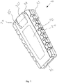
- figure 1 shows a first embodiment of a hand lamp 10 according to the invention.
- this can have a base body 20, which can be operatively connected to the other components.
- a grip area 21 can be arranged on the side of the base body, which enables the hand lamp to be held particularly firmly.
- a carrying clip 23 can be arranged on a rear side, by means of which the hand-held lamp can be arranged on a belt, for example.
- a U-shaped receptacle 25 which can be formed from at least two webs 26 and 27, preferably with the base body 20.
- a light source 30 is arranged, which can also have a distance meter. The illuminant and/or the range finder can be pivoted in the socket 25 .
- the illuminant and/or the range finder can be provided approximately orthogonally to a longitudinal axis of the hand lamp or a longitudinal axis of the webs 26 and 27 .
- a variable beam angle of the light source 30 of the hand lamp can be provided in relation to the base body of the hand lamp.
- the direction in which the lamp emits light can be changed at right angles to a longitudinal axis of the base body or the longitudinal axis of the webs 26 and 27 parallel to them or at any angle in between.
- the lighting means 30 and/or the range finder are mounted freely rotatable about its axis in the receptacle 25 .
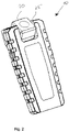
- figure 3 describes a second embodiment of the hand lamp 40 according to the invention, which can have a first light source 30 with or without a distance meter. This can be connected via adapter elements 31 to webs 32 arranged on the side. This ensures that the illuminant 30 and/or the distance meter on the hand lamp can be replaced.
- a free space 50 can be formed, in particular between the light source 30 and a base body of the hand lamp, which space can accommodate a magnifying glass, for example.
- the magnifying glass is delimited by an upper edge 51 or a lower edge 52. In principle, however, the magnifying glass can also be provided between the webs 42 and 43 without a mount at the top or bottom.
- the edge 51 does not form a bridge between the webs 42 and 43 and thus does not form an interruption in the intended shape, which the two webs 42 and 43, in particular in connection with the base body 48, form.
- a U-shaped form is to be assumed even in this case.
- a second illuminant with or without a distance meter can be provided in an area between the base body 48 and the illuminant 30 with or without a distance meter. In principle, it is expedient to provide only one distance meter. However, this can have elements that are arranged in different areas of the hand lamp.
- a first part of a distance measuring device for example a transmission device for transmitting an acoustic or electromagnetic signal, could be arranged in the area of illuminant 30, whereas a receiver for the acoustic or electromagnetic signal from the element in the area of illuminant 30 could be arranged in the area of illuminant 41 is provided.
- the arrangement of the two elements can also be reversed.
- the additional illuminant and/or the range finder can also be provided in a foot area of the hand lamp, with a base body 48 being provided between the illuminant 30 with or without range finder and the second illuminant 41 with or without range finder.
- the hand lamp 40 can have a button 44, by means of which the hand lamp can be switched on and off and/or a basic brightness of the hand lamp and/or a distance-dependent brightness of the hand lamp (the lamp/lamps) can be adjusted.
- the hand lamp can have a display 45 which shows the status of a management memory provided, which is provided in the base body 48, for example.
- a connection for a charging means 46 can be provided, for example a USB connection, via which an energy storage device of the hand-held lamp can be charged within the hand-held lamp.
- a hook 47 can be provided for proper attachment, which can preferably be rotatably attached to the base body 48 .
- the detachable connection between the lamp 30 and the webs 42 and 43 via the adapter elements 31 can make it possible to replace the lamp and/or the distance meter at a head end of the hand lamp.
- the hand lamp which can also have another lamp, can be adapted to the conditions as required.
- a lamp with lower or higher luminosity, a lamp with or without a distance meter or another device that can be operated by means of electricity can be provided on the hand lamp in the head area.
- the illuminant 30 with or without a range finder according to FIG figure 3 can be provided in a socket in relation to which the illuminant and/or the distance meter can be rotatably mounted.
- the axis of rotation is basically arbitrary, but can preferably be provided approximately orthogonally to the webs 42 and 43 or transversely to a longitudinal axis of the base body 48 .
- the lighting means can be freely adjusted in its lighting direction with respect to the base body, with or without a distance meter.
- the second light source 41 can also be provided on the hand lamp 40 with the same axis as the light source 30 or with a different one.
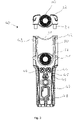
- figure 4 shows the second embodiment of the present invention in an assembled state between the illuminant 30 and/or the distance meter the body 48 via the webs 42 and 43.
- the hand lamp itself is in figure 4 provided in a charging station 60, which has a mechanism 61, via which the hand lamp can be actuated, ie switched on and off.
- the charging station can be provided with a twilight or photo diode for detecting the brightness in the environment.
- the charging station can also have a distance meter or a motion detector, by means of which the brightness of the hand lamp can be regulated depending on the distance between the charging station and an object in the direction in which the hand lamp is illuminated, or the hand lamp can be switched on and off depending on a movement in front of the hand lamp.
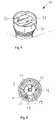
- FIG 5 shows a light source 70 which has a distance measuring device.
- the distance measuring device can be designed with a transmitter 72 and a receiver 73 .
- a photoemissive element 74 may be provided to emit light from the illuminant.
- the range finder can be designed to interact with the illuminant or with the photo-emitting element in such a way that when the distance between the range finder and an object or a surface is small, the luminosity of the illuminant or the photo-emitting element is compared to a larger distance between the range finder and an object or a surface is reduced.
- the measuring devices 72 and 73 of the distance meter are functionally aligned in the same or a similar direction as the light emitted by the lamp.
- figure 6 shows a top view of an embodiment of the illuminant with a photo-emitting element 74 and the devices 72 and 73 of the distance meter, which may have a housing 78 and/or a lens or glass 75 and/or a reflector 79 holding the photoemissive element 74 and/or an insulating ring 77.
Landscapes
- Engineering & Computer Science (AREA)
- General Engineering & Computer Science (AREA)
- Arrangement Of Elements, Cooling, Sealing, Or The Like Of Lighting Devices (AREA)
- Non-Portable Lighting Devices Or Systems Thereof (AREA)
- Circuit Arrangement For Electric Light Sources In General (AREA)
Claims (13)
- Lampe torche munie de deux sources lumineuses (30,41) exploitées électriquement et d'un dispositif de mesure de distance (72,73) qui détermine la distance entre le dispositif de mesure de distance (72,73) en direction d'un objet ou d'une surface caractérisée de sorte qu'un système régulateur est prévu se trouvant en liaison coopérante avec le dispositif de mesure de distance (72,73) réglant la luminosité d'au minimum de l'une des sources lumineuses (30) en dépendance de la distance donnée et arrêtant directement au minimum une deuxième source lumineuse en étant inférieure à une distance donnée par laquelle une intensité lumineuse résiduelle réduite de la lampe torche est prévue de sorte que le système régulateur est formé de sorte qu'au minimum la deuxième source lumineuse après achèvement d'une gradation d'au minimum une source lumineuse (30) avec une force lumineuse adaptée est effectuée jusqu'une intensité lumineuse totale dépendamment de la distance des sources lumineuses (30) à la fin de la gradation où une source lumineuse (30,41) pourrait être un élément de source lumineuse individuel ou le cas échéant un groupe d'éléments de source lumineuse.
- Lampe torche selon la revendication 1 est caractérisée de sorte que les sources lumineuses (30,41) et/ou les dispositifs de mesure de distance (72,73) sont réglables.
- Lampe torche selon la revendication 1 ou 2 est caractérisée de sorte que le dispositif de mesure de distance (72,73) est orienté au minimum dans une direction du fasiceau des sources lumineuses (30,41) déterminant la distance.
- Lampe torche selon la revendication 1 jusqu'à 3 est caractérisée de sorte que le dispositif de mesure de distance (72,73) et/ou les sources lumineuses (30) sont reliés de manière amovible au corps de base de la lampe torche (10,40).
- Lampe torche selon la revendication 1 jusqu'à 4 est caractérisée de sorte que le dispositif de mesure de distance (72,73) constitue un élément unitaire avec au minimum une source lumineuse (30).
- Lampe torche selon la revendication 1 jusqu'à 5 est caractérisée de sorte qu'un élément d'actionnement (44) est prévu par le biais duquel la force lumineuse des sources lumineuses (30,41) est réglable dépendamment de la distance.
- Lampe torche selon la revendication 1 jusqu'à 6 est caractérisée de sorte que le dispositif de mesure de distance (72,73) est réglable/est réglé pour déterminer la distance entre la source lumineuse respective (30,41) en direction de la surface ou vers l'objet où la force de luminosité de la source lumineuse (30) est réglable dépendamment de la distance et/ou où des informations relatives à la position des sources lumineuses (30) sont déposables/sont déposées vis-à-vis du dispositif de mesure de distance (72,73) de préférence au sein du système régulateur.
- Lampe torche selon la revendication 1 jusqu'à 7 est caractérisée de sorte qu'une douille (32) est prévue pour au minimum une source lumineuse (30) et/ou le dispositif de mesure de distance (72,73) est prévu présentant au minimum une nervure longitudinale (42,43) fournissant au minimum une liaison électrique entre la source d'énergie et la source lumineuse et/ou le dispositif de mesure de distance.
- Lampe torche selon la revendication 1 jusqu'à 8 est caractérisée de sorte qu'au minimum deux nervures longitudinales (42,43) sont prévues où au minimum une source lumineuse (30) et/ou le dispositif de mesure de distance (72,73) sont disposés entourant au minimum et à titre partiel la source lumineuse (30) et/ou le dispositif de mesure de distance (72,73).
- Lampe torche selon la revendication 9 est caractérisée de sorte que le cadre formé par les nervures longitudinales (42,43) présente au minimum une ouverture sur un côté et notamment formée en forme de U.
- Lampe torche selon la revendication 1 jusqu'à 10 est caractérisée de sorte que la lampe torche présente un levé pour une source d'énergie raccordable d'une manière détachable.
- Source lumineuse pour une lampe torche présentant : un groupe d'éléments de sources lumineuses, un dispositif de mesure de distance (72,73) orienté vers la direction du faciseau des éléments de sources lumineuses déterminant la distance entre la source lumineuse (30) et le cas échéant le dispositif de mesure de distance (72,73) et une surface ou un objet et un système régulateur se trouvant en liaison coopérante avec le dispositif de mesure de distance (72,73), réglant la force de luminosité d'au minimum un élément de source lumineuse dépendamment de la distance donnée et coupant directement au minimum un deuxième élément de source lumineuse de manière inférieure de cette distance donnée par le biais de laquelle une intensité lumineuse résiduelle réduite de l'élément de la source lumineuse est fournie et que le système régulateur est formé de sorte que le deuxième élément de la source lumineuse au minimum à l'achèvement de la gradation au minimum de l'élément de la source lumineuse via la force de luminosité adaptée se mette en marche en direction de la densité lumineuse totale des éléments de la source lumineuse dépendamment de la distance donnée.
- Procédé d'éclairage adaptif d'un objet ou d'une surface par le biais d'une lampe torche selon la revendication 1 jusqu'à 11 dans laquelle une distance entre le dispositif de mesure de distance (72,73) et une surface et un objet est déterminée par le biais du dispositif de mesure de distance (72,73) et la distance donnée d'un système régulateur est mis à disposition réglant la force de luminosité d'au minimum deux éléments de sources lumineuses (30,41) basé sur une distance donnée où au minimum une source lumineuse est tamisée et au minimum un élément de source lumineuse additionnel est mis hors marche directement par le biais duquel en premier lieu une intensité lumineuse résiduelle réduite de la lampe torche est fournie et que le système régulateur à l'achèvement du tamisage d'au minimum un élément de source lumineuse d'au minimum du deuxième élément de source lumineuse est coupé grâce à la force lumineuse adaptée jusqu'à une intensité lumineuse totale dépendamment de la distance des sources lumineuses et ce à l'achèvement du tamisage.
Applications Claiming Priority (7)
| Application Number | Priority Date | Filing Date | Title |
|---|---|---|---|
| EP18215033.4A EP3671033A1 (fr) | 2018-12-21 | 2018-12-21 | Dispositif d'illumination réglable |
| DE102018133305.6A DE102018133305A1 (de) | 2018-12-21 | 2018-12-21 | Regelbare Lampe |
| DE102019116983 | 2019-06-24 | ||
| DE102019116987 | 2019-06-24 | ||
| EP19181946 | 2019-06-24 | ||
| DE202019103843 | 2019-07-12 | ||
| EP19185966 | 2019-07-12 |
Publications (2)
| Publication Number | Publication Date |
|---|---|
| EP3671034A1 EP3671034A1 (fr) | 2020-06-24 |
| EP3671034B1 true EP3671034B1 (fr) | 2022-04-27 |
Family
ID=68841039
Family Applications (1)
| Application Number | Title | Priority Date | Filing Date |
|---|---|---|---|
| EP19216880.5A Active EP3671034B1 (fr) | 2018-12-21 | 2019-12-17 | Lampe réglable |
Country Status (4)
| Country | Link |
|---|---|
| EP (1) | EP3671034B1 (fr) |
| DE (1) | DE202019005857U1 (fr) |
| ES (1) | ES2923575T3 (fr) |
| PL (1) | PL3671034T3 (fr) |
Families Citing this family (3)
| Publication number | Priority date | Publication date | Assignee | Title |
|---|---|---|---|---|
| DE102022134887A1 (de) * | 2022-12-28 | 2024-07-04 | Pfanner Schutzbekleidung Gmbh | Helmlicht, Schutzhelm mit einem Helmlicht und Verfahren zum Betreiben eines Helmlichts |
| DE102022134903B4 (de) * | 2022-12-28 | 2024-08-01 | Pfanner Schutzbekleidung Gmbh | Helmlicht, Schutzhelm mit einem Helmlicht und Verfahren zum Betreiben eines Helmlichts |
| US20260016151A1 (en) * | 2024-07-10 | 2026-01-15 | Infinity X1 Llc | Protective lighting system and methods |
Citations (1)
| Publication number | Priority date | Publication date | Assignee | Title |
|---|---|---|---|---|
| WO2017192911A1 (fr) * | 2016-05-04 | 2017-11-09 | Idea Pond Llc | Module de commande adaptatif de lampe torche |
Family Cites Families (3)
| Publication number | Priority date | Publication date | Assignee | Title |
|---|---|---|---|---|
| US6445884B1 (en) * | 1995-06-22 | 2002-09-03 | 3Dv Systems, Ltd. | Camera with through-the-lens lighting |
| JP2009083835A (ja) * | 2007-09-14 | 2009-04-23 | Koito Mfg Co Ltd | 車両用ランプ |
| DE102015113338B4 (de) * | 2015-08-13 | 2017-10-05 | Karl Leibinger Medizintechnik Gmbh & Co. Kg | Handgriffvorrichtung für eine Operationsleuchte mit Sprachsteuerung sowie Operationsleuchte |
-
2019
- 2019-12-17 DE DE202019005857.5U patent/DE202019005857U1/de not_active Expired - Lifetime
- 2019-12-17 EP EP19216880.5A patent/EP3671034B1/fr active Active
- 2019-12-17 PL PL19216880.5T patent/PL3671034T3/pl unknown
- 2019-12-17 ES ES19216880T patent/ES2923575T3/es active Active
Patent Citations (1)
| Publication number | Priority date | Publication date | Assignee | Title |
|---|---|---|---|---|
| WO2017192911A1 (fr) * | 2016-05-04 | 2017-11-09 | Idea Pond Llc | Module de commande adaptatif de lampe torche |
Also Published As
| Publication number | Publication date |
|---|---|
| EP3671034A1 (fr) | 2020-06-24 |
| PL3671034T3 (pl) | 2022-09-12 |
| ES2923575T3 (es) | 2022-09-28 |
| DE202019005857U1 (de) | 2022-10-10 |
Similar Documents
| Publication | Publication Date | Title |
|---|---|---|
| DE19781679B4 (de) | Solaraussenlampe | |
| EP3671034B1 (fr) | Lampe réglable | |
| US6793364B2 (en) | Non-lethal visual bird dispersal system | |
| EP1568938A1 (fr) | Lampe chirurgicale et procédé d'illumination d'un champ opératoire | |
| DE102020105965B4 (de) | Leuchte mit veränderbarem Abstrahlwinkel und fester Lichtstärke in der Mitte des Strahls | |
| DE102015113339A1 (de) | Operationsleuchte mit Helligkeitsregulierung | |
| DE102018105878A1 (de) | Verfahren und Systeme zum Steuern von Licht | |
| DE202014001980U1 (de) | Schalter-Einheit | |
| WO2016041994A1 (fr) | Dispositif d'éclairage et procédé permettant de faire fonctionner un éclairage | |
| DE202007013752U1 (de) | Schaltbarer Leucht- und Signalkörper und Hundehalsring | |
| US9629213B2 (en) | Variably controlled lighting mechanism for feeders | |
| DE102011075116A1 (de) | Raumbeleuchtungssystem zum beleuchten eines raums | |
| DE102005034600A1 (de) | Beleuchtungsvorrichtung | |
| EP3757455A1 (fr) | Lampe réglable | |
| EP2902698B1 (fr) | Éclairage | |
| DE102016204370B4 (de) | Infrarot-Leuchte für ein Fahrzeug | |
| EP3671033A1 (fr) | Dispositif d'illumination réglable | |
| DE102018133305A1 (de) | Regelbare Lampe | |
| DE202014007579U1 (de) | Leuchten und Leuchtensysteme zur Erweiterung und Verbesserung der visuellen Auswertbarkeit und Beurteilung von Oberflächen und angeregten Fluoreszenzen | |
| EP1621809B1 (fr) | Corps lumineux | |
| EP1607678A2 (fr) | Lampe avec des diodes électroluminescentes pour produire un faisceau large ou un faisceau ponctuel | |
| EP3427542A1 (fr) | Régulation d'un système de del et système d'éclairage à del | |
| DE20006963U1 (de) | Signaleinrichtung | |
| DE202026101538U1 (de) | Tragbare Leuchte zur Bodenausleuchtung | |
| DE102011111970A1 (de) | LED-Modul-System mit einem LED-Modul |
Legal Events
| Date | Code | Title | Description |
|---|---|---|---|
| REG | Reference to a national code |
Ref country code: DE Ref legal event code: R138 Ref document number: 202019005857 Country of ref document: DE Free format text: GERMAN DOCUMENT NUMBER IS 502019004192 |
|
| PUAI | Public reference made under article 153(3) epc to a published international application that has entered the european phase |
Free format text: ORIGINAL CODE: 0009012 |
|
| STAA | Information on the status of an ep patent application or granted ep patent |
Free format text: STATUS: THE APPLICATION HAS BEEN PUBLISHED |
|
| AK | Designated contracting states |
Kind code of ref document: A1 Designated state(s): AL AT BE BG CH CY CZ DE DK EE ES FI FR GB GR HR HU IE IS IT LI LT LU LV MC MK MT NL NO PL PT RO RS SE SI SK SM TR |
|
| AX | Request for extension of the european patent |
Extension state: BA ME |
|
| STAA | Information on the status of an ep patent application or granted ep patent |
Free format text: STATUS: REQUEST FOR EXAMINATION WAS MADE |
|
| 17P | Request for examination filed |
Effective date: 20200813 |
|
| RBV | Designated contracting states (corrected) |
Designated state(s): AL AT BE BG CH CY CZ DE DK EE ES FI FR GB GR HR HU IE IS IT LI LT LU LV MC MK MT NL NO PL PT RO RS SE SI SK SM TR |
|
| STAA | Information on the status of an ep patent application or granted ep patent |
Free format text: STATUS: EXAMINATION IS IN PROGRESS |
|
| 17Q | First examination report despatched |
Effective date: 20201209 |
|
| GRAP | Despatch of communication of intention to grant a patent |
Free format text: ORIGINAL CODE: EPIDOSNIGR1 |
|
| STAA | Information on the status of an ep patent application or granted ep patent |
Free format text: STATUS: GRANT OF PATENT IS INTENDED |
|
| RIC1 | Information provided on ipc code assigned before grant |
Ipc: F21Y 115/10 20160101ALN20211104BHEP Ipc: H05B 33/08 20200101ALI20211104BHEP Ipc: F21L 4/00 20060101ALI20211104BHEP Ipc: F21V 23/04 20060101AFI20211104BHEP |
|
| INTG | Intention to grant announced |
Effective date: 20211126 |
|
| RIN1 | Information on inventor provided before grant (corrected) |
Inventor name: TAVOSANIS, DANIEL Inventor name: TAVOSANIS, TESS Inventor name: TAVOSANIS, VITTORIO S. |
|
| GRAS | Grant fee paid |
Free format text: ORIGINAL CODE: EPIDOSNIGR3 |
|
| GRAA | (expected) grant |
Free format text: ORIGINAL CODE: 0009210 |
|
| STAA | Information on the status of an ep patent application or granted ep patent |
Free format text: STATUS: THE PATENT HAS BEEN GRANTED |
|
| AK | Designated contracting states |
Kind code of ref document: B1 Designated state(s): AL AT BE BG CH CY CZ DE DK EE ES FI FR GB GR HR HU IE IS IT LI LT LU LV MC MK MT NL NO PL PT RO RS SE SI SK SM TR |
|
| REG | Reference to a national code |
Ref country code: GB Ref legal event code: FG4D Free format text: NOT ENGLISH |
|
| REG | Reference to a national code |
Ref country code: CH Ref legal event code: EP |
|
| REG | Reference to a national code |
Ref country code: AT Ref legal event code: REF Ref document number: 1487185 Country of ref document: AT Kind code of ref document: T Effective date: 20220515 |
|
| REG | Reference to a national code |
Ref country code: DE Ref legal event code: R096 Ref document number: 502019004192 Country of ref document: DE |
|
| REG | Reference to a national code |
Ref country code: IE Ref legal event code: FG4D Free format text: LANGUAGE OF EP DOCUMENT: GERMAN |
|
| REG | Reference to a national code |
Ref country code: NL Ref legal event code: FP |
|
| REG | Reference to a national code |
Ref country code: PT Ref legal event code: SC4A Ref document number: 3671034 Country of ref document: PT Date of ref document: 20220725 Kind code of ref document: T Free format text: AVAILABILITY OF NATIONAL TRANSLATION Effective date: 20220720 |
|
| REG | Reference to a national code |
Ref country code: GR Ref legal event code: EP Ref document number: 20220401491 Country of ref document: GR Effective date: 20220808 |
|
| REG | Reference to a national code |
Ref country code: SE Ref legal event code: TRGR |
|
| REG | Reference to a national code |
Ref country code: LT Ref legal event code: MG9D |
|
| REG | Reference to a national code |
Ref country code: ES Ref legal event code: FG2A Ref document number: 2923575 Country of ref document: ES Kind code of ref document: T3 Effective date: 20220928 |
|
| PG25 | Lapsed in a contracting state [announced via postgrant information from national office to epo] |
Ref country code: NO Free format text: LAPSE BECAUSE OF FAILURE TO SUBMIT A TRANSLATION OF THE DESCRIPTION OR TO PAY THE FEE WITHIN THE PRESCRIBED TIME-LIMIT Effective date: 20220727 Ref country code: LT Free format text: LAPSE BECAUSE OF FAILURE TO SUBMIT A TRANSLATION OF THE DESCRIPTION OR TO PAY THE FEE WITHIN THE PRESCRIBED TIME-LIMIT Effective date: 20220427 Ref country code: HR Free format text: LAPSE BECAUSE OF FAILURE TO SUBMIT A TRANSLATION OF THE DESCRIPTION OR TO PAY THE FEE WITHIN THE PRESCRIBED TIME-LIMIT Effective date: 20220427 Ref country code: FI Free format text: LAPSE BECAUSE OF FAILURE TO SUBMIT A TRANSLATION OF THE DESCRIPTION OR TO PAY THE FEE WITHIN THE PRESCRIBED TIME-LIMIT Effective date: 20220427 Ref country code: BG Free format text: LAPSE BECAUSE OF FAILURE TO SUBMIT A TRANSLATION OF THE DESCRIPTION OR TO PAY THE FEE WITHIN THE PRESCRIBED TIME-LIMIT Effective date: 20220727 |
|
| PG25 | Lapsed in a contracting state [announced via postgrant information from national office to epo] |
Ref country code: RS Free format text: LAPSE BECAUSE OF FAILURE TO SUBMIT A TRANSLATION OF THE DESCRIPTION OR TO PAY THE FEE WITHIN THE PRESCRIBED TIME-LIMIT Effective date: 20220427 Ref country code: LV Free format text: LAPSE BECAUSE OF FAILURE TO SUBMIT A TRANSLATION OF THE DESCRIPTION OR TO PAY THE FEE WITHIN THE PRESCRIBED TIME-LIMIT Effective date: 20220427 Ref country code: IS Free format text: LAPSE BECAUSE OF FAILURE TO SUBMIT A TRANSLATION OF THE DESCRIPTION OR TO PAY THE FEE WITHIN THE PRESCRIBED TIME-LIMIT Effective date: 20220827 |
|
| REG | Reference to a national code |
Ref country code: DE Ref legal event code: R097 Ref document number: 502019004192 Country of ref document: DE |
|
| PG25 | Lapsed in a contracting state [announced via postgrant information from national office to epo] |
Ref country code: SM Free format text: LAPSE BECAUSE OF FAILURE TO SUBMIT A TRANSLATION OF THE DESCRIPTION OR TO PAY THE FEE WITHIN THE PRESCRIBED TIME-LIMIT Effective date: 20220427 Ref country code: SK Free format text: LAPSE BECAUSE OF FAILURE TO SUBMIT A TRANSLATION OF THE DESCRIPTION OR TO PAY THE FEE WITHIN THE PRESCRIBED TIME-LIMIT Effective date: 20220427 Ref country code: RO Free format text: LAPSE BECAUSE OF FAILURE TO SUBMIT A TRANSLATION OF THE DESCRIPTION OR TO PAY THE FEE WITHIN THE PRESCRIBED TIME-LIMIT Effective date: 20220427 Ref country code: EE Free format text: LAPSE BECAUSE OF FAILURE TO SUBMIT A TRANSLATION OF THE DESCRIPTION OR TO PAY THE FEE WITHIN THE PRESCRIBED TIME-LIMIT Effective date: 20220427 Ref country code: DK Free format text: LAPSE BECAUSE OF FAILURE TO SUBMIT A TRANSLATION OF THE DESCRIPTION OR TO PAY THE FEE WITHIN THE PRESCRIBED TIME-LIMIT Effective date: 20220427 |
|
| PLBE | No opposition filed within time limit |
Free format text: ORIGINAL CODE: 0009261 |
|
| STAA | Information on the status of an ep patent application or granted ep patent |
Free format text: STATUS: NO OPPOSITION FILED WITHIN TIME LIMIT |
|
| PG25 | Lapsed in a contracting state [announced via postgrant information from national office to epo] |
Ref country code: AL Free format text: LAPSE BECAUSE OF FAILURE TO SUBMIT A TRANSLATION OF THE DESCRIPTION OR TO PAY THE FEE WITHIN THE PRESCRIBED TIME-LIMIT Effective date: 20220427 |
|
| 26N | No opposition filed |
Effective date: 20230130 |
|
| PG25 | Lapsed in a contracting state [announced via postgrant information from national office to epo] |
Ref country code: SI Free format text: LAPSE BECAUSE OF FAILURE TO SUBMIT A TRANSLATION OF THE DESCRIPTION OR TO PAY THE FEE WITHIN THE PRESCRIBED TIME-LIMIT Effective date: 20220427 |
|
| PGFP | Annual fee paid to national office [announced via postgrant information from national office to epo] |
Ref country code: IT Payment date: 20221231 Year of fee payment: 4 |
|
| REG | Reference to a national code |
Ref country code: DE Ref legal event code: R119 Ref document number: 502019004192 Country of ref document: DE |
|
| PG25 | Lapsed in a contracting state [announced via postgrant information from national office to epo] |
Ref country code: CZ Free format text: LAPSE BECAUSE OF NON-PAYMENT OF DUE FEES Effective date: 20221217 |
|
| REG | Reference to a national code |
Ref country code: CH Ref legal event code: PL |
|
| REG | Reference to a national code |
Ref country code: SE Ref legal event code: EUG |
|
| REG | Reference to a national code |
Ref country code: NL Ref legal event code: MM Effective date: 20230101 |
|
| REG | Reference to a national code |
Ref country code: BE Ref legal event code: MM Effective date: 20221231 |
|
| PG25 | Lapsed in a contracting state [announced via postgrant information from national office to epo] |
Ref country code: LU Free format text: LAPSE BECAUSE OF NON-PAYMENT OF DUE FEES Effective date: 20221217 |
|
| PG25 | Lapsed in a contracting state [announced via postgrant information from national office to epo] |
Ref country code: NL Free format text: LAPSE BECAUSE OF NON-PAYMENT OF DUE FEES Effective date: 20230101 |
|
| PG25 | Lapsed in a contracting state [announced via postgrant information from national office to epo] |
Ref country code: SE Free format text: LAPSE BECAUSE OF NON-PAYMENT OF DUE FEES Effective date: 20221218 Ref country code: PT Free format text: LAPSE BECAUSE OF NON-PAYMENT OF DUE FEES Effective date: 20230918 Ref country code: LI Free format text: LAPSE BECAUSE OF NON-PAYMENT OF DUE FEES Effective date: 20221231 Ref country code: IE Free format text: LAPSE BECAUSE OF NON-PAYMENT OF DUE FEES Effective date: 20221217 Ref country code: DE Free format text: LAPSE BECAUSE OF NON-PAYMENT OF DUE FEES Effective date: 20230701 Ref country code: CH Free format text: LAPSE BECAUSE OF NON-PAYMENT OF DUE FEES Effective date: 20221231 |
|
| PG25 | Lapsed in a contracting state [announced via postgrant information from national office to epo] |
Ref country code: GR Free format text: LAPSE BECAUSE OF NON-PAYMENT OF DUE FEES Effective date: 20230705 Ref country code: FR Free format text: LAPSE BECAUSE OF NON-PAYMENT OF DUE FEES Effective date: 20221231 Ref country code: BE Free format text: LAPSE BECAUSE OF NON-PAYMENT OF DUE FEES Effective date: 20221231 |
|
| REG | Reference to a national code |
Ref country code: ES Ref legal event code: FD2A Effective date: 20240126 |
|
| PG25 | Lapsed in a contracting state [announced via postgrant information from national office to epo] |
Ref country code: HU Free format text: LAPSE BECAUSE OF FAILURE TO SUBMIT A TRANSLATION OF THE DESCRIPTION OR TO PAY THE FEE WITHIN THE PRESCRIBED TIME-LIMIT; INVALID AB INITIO Effective date: 20191217 |
|
| PG25 | Lapsed in a contracting state [announced via postgrant information from national office to epo] |
Ref country code: ES Free format text: LAPSE BECAUSE OF NON-PAYMENT OF DUE FEES Effective date: 20221218 |
|
| PG25 | Lapsed in a contracting state [announced via postgrant information from national office to epo] |
Ref country code: ES Free format text: LAPSE BECAUSE OF NON-PAYMENT OF DUE FEES Effective date: 20221218 Ref country code: CY Free format text: LAPSE BECAUSE OF FAILURE TO SUBMIT A TRANSLATION OF THE DESCRIPTION OR TO PAY THE FEE WITHIN THE PRESCRIBED TIME-LIMIT Effective date: 20220427 |
|
| PG25 | Lapsed in a contracting state [announced via postgrant information from national office to epo] |
Ref country code: PL Free format text: LAPSE BECAUSE OF NON-PAYMENT OF DUE FEES Effective date: 20221217 Ref country code: MK Free format text: LAPSE BECAUSE OF FAILURE TO SUBMIT A TRANSLATION OF THE DESCRIPTION OR TO PAY THE FEE WITHIN THE PRESCRIBED TIME-LIMIT Effective date: 20220427 |
|
| PG25 | Lapsed in a contracting state [announced via postgrant information from national office to epo] |
Ref country code: MC Free format text: LAPSE BECAUSE OF FAILURE TO SUBMIT A TRANSLATION OF THE DESCRIPTION OR TO PAY THE FEE WITHIN THE PRESCRIBED TIME-LIMIT Effective date: 20220427 |
|
| PG25 | Lapsed in a contracting state [announced via postgrant information from national office to epo] |
Ref country code: MC Free format text: LAPSE BECAUSE OF FAILURE TO SUBMIT A TRANSLATION OF THE DESCRIPTION OR TO PAY THE FEE WITHIN THE PRESCRIBED TIME-LIMIT Effective date: 20220427 |
|
| GBPC | Gb: european patent ceased through non-payment of renewal fee |
Effective date: 20231217 |
|
| PG25 | Lapsed in a contracting state [announced via postgrant information from national office to epo] |
Ref country code: TR Free format text: LAPSE BECAUSE OF NON-PAYMENT OF DUE FEES Effective date: 20221217 Ref country code: MT Free format text: LAPSE BECAUSE OF FAILURE TO SUBMIT A TRANSLATION OF THE DESCRIPTION OR TO PAY THE FEE WITHIN THE PRESCRIBED TIME-LIMIT Effective date: 20220427 |
|
| PG25 | Lapsed in a contracting state [announced via postgrant information from national office to epo] |
Ref country code: GB Free format text: LAPSE BECAUSE OF NON-PAYMENT OF DUE FEES Effective date: 20231217 |
|
| PG25 | Lapsed in a contracting state [announced via postgrant information from national office to epo] |
Ref country code: GB Free format text: LAPSE BECAUSE OF NON-PAYMENT OF DUE FEES Effective date: 20231217 |
|
| PG25 | Lapsed in a contracting state [announced via postgrant information from national office to epo] |
Ref country code: BG Free format text: LAPSE BECAUSE OF FAILURE TO SUBMIT A TRANSLATION OF THE DESCRIPTION OR TO PAY THE FEE WITHIN THE PRESCRIBED TIME-LIMIT Effective date: 20220427 |
|
| PG25 | Lapsed in a contracting state [announced via postgrant information from national office to epo] |
Ref country code: BG Free format text: LAPSE BECAUSE OF FAILURE TO SUBMIT A TRANSLATION OF THE DESCRIPTION OR TO PAY THE FEE WITHIN THE PRESCRIBED TIME-LIMIT Effective date: 20220427 |
|
| REG | Reference to a national code |
Ref country code: AT Ref legal event code: MM01 Ref document number: 1487185 Country of ref document: AT Kind code of ref document: T Effective date: 20241217 |
|
| PG25 | Lapsed in a contracting state [announced via postgrant information from national office to epo] |
Ref country code: AT Free format text: LAPSE BECAUSE OF NON-PAYMENT OF DUE FEES Effective date: 20241217 |
|
| PGFP | Annual fee paid to national office [announced via postgrant information from national office to epo] |
Ref country code: AT Payment date: 20260410 Year of fee payment: 5 |