EP3671035B1 - Luminaire pourvu de nervures de refroidissement dans le boîtier de luminaire - Google Patents
Luminaire pourvu de nervures de refroidissement dans le boîtier de luminaire Download PDFInfo
- Publication number
- EP3671035B1 EP3671035B1 EP19218415.8A EP19218415A EP3671035B1 EP 3671035 B1 EP3671035 B1 EP 3671035B1 EP 19218415 A EP19218415 A EP 19218415A EP 3671035 B1 EP3671035 B1 EP 3671035B1
- Authority
- EP
- European Patent Office
- Prior art keywords
- light
- rib
- fins
- light emission
- rib arrangement
- Prior art date
- Legal status (The legal status is an assumption and is not a legal conclusion. Google has not performed a legal analysis and makes no representation as to the accuracy of the status listed.)
- Active
Links
Images


Classifications
-
- F—MECHANICAL ENGINEERING; LIGHTING; HEATING; WEAPONS; BLASTING
- F21—LIGHTING
- F21V—FUNCTIONAL FEATURES OR DETAILS OF LIGHTING DEVICES OR SYSTEMS THEREOF; STRUCTURAL COMBINATIONS OF LIGHTING DEVICES WITH OTHER ARTICLES, NOT OTHERWISE PROVIDED FOR
- F21V29/00—Protecting lighting devices from thermal damage; Cooling or heating arrangements specially adapted for lighting devices or systems
- F21V29/50—Cooling arrangements
- F21V29/70—Cooling arrangements characterised by passive heat-dissipating elements, e.g. heat-sinks
- F21V29/74—Cooling arrangements characterised by passive heat-dissipating elements, e.g. heat-sinks with fins or blades
- F21V29/75—Cooling arrangements characterised by passive heat-dissipating elements, e.g. heat-sinks with fins or blades with fins or blades having different shapes, thicknesses or spacing
-
- F—MECHANICAL ENGINEERING; LIGHTING; HEATING; WEAPONS; BLASTING
- F21—LIGHTING
- F21V—FUNCTIONAL FEATURES OR DETAILS OF LIGHTING DEVICES OR SYSTEMS THEREOF; STRUCTURAL COMBINATIONS OF LIGHTING DEVICES WITH OTHER ARTICLES, NOT OTHERWISE PROVIDED FOR
- F21V15/00—Protecting lighting devices from damage
- F21V15/01—Housings, e.g. material or assembling of housing parts
-
- F—MECHANICAL ENGINEERING; LIGHTING; HEATING; WEAPONS; BLASTING
- F21—LIGHTING
- F21V—FUNCTIONAL FEATURES OR DETAILS OF LIGHTING DEVICES OR SYSTEMS THEREOF; STRUCTURAL COMBINATIONS OF LIGHTING DEVICES WITH OTHER ARTICLES, NOT OTHERWISE PROVIDED FOR
- F21V5/00—Refractors for light sources
- F21V5/007—Array of lenses or refractors for a cluster of light sources, e.g. for arrangement of multiple light sources in one plane
-
- F—MECHANICAL ENGINEERING; LIGHTING; HEATING; WEAPONS; BLASTING
- F21—LIGHTING
- F21W—INDEXING SCHEME ASSOCIATED WITH SUBCLASSES F21K, F21L, F21S and F21V, RELATING TO USES OR APPLICATIONS OF LIGHTING DEVICES OR SYSTEMS
- F21W2131/00—Use or application of lighting devices or systems not provided for in codes F21W2102/00-F21W2121/00
- F21W2131/10—Outdoor lighting
- F21W2131/103—Outdoor lighting of streets or roads
-
- F—MECHANICAL ENGINEERING; LIGHTING; HEATING; WEAPONS; BLASTING
- F21—LIGHTING
- F21Y—INDEXING SCHEME ASSOCIATED WITH SUBCLASSES F21K, F21L, F21S and F21V, RELATING TO THE FORM OR THE KIND OF THE LIGHT SOURCES OR OF THE COLOUR OF THE LIGHT EMITTED
- F21Y2105/00—Planar light sources
- F21Y2105/10—Planar light sources comprising a two-dimensional [2D] array of point-like light-generating elements
- F21Y2105/14—Planar light sources comprising a two-dimensional [2D] array of point-like light-generating elements characterised by the overall shape of the two-dimensional [2D] array
- F21Y2105/16—Planar light sources comprising a two-dimensional [2D] array of point-like light-generating elements characterised by the overall shape of the two-dimensional [2D] array square or rectangular, e.g. for light panels
-
- F—MECHANICAL ENGINEERING; LIGHTING; HEATING; WEAPONS; BLASTING
- F21—LIGHTING
- F21Y—INDEXING SCHEME ASSOCIATED WITH SUBCLASSES F21K, F21L, F21S and F21V, RELATING TO THE FORM OR THE KIND OF THE LIGHT SOURCES OR OF THE COLOUR OF THE LIGHT EMITTED
- F21Y2115/00—Light-generating elements of semiconductor light sources
- F21Y2115/10—Light-emitting diodes [LED]
Definitions
- the invention relates to a lamp with a lamp housing in which a heat sink is arranged, according to the preamble of claim 1.
- Generic lights include a light housing with an interior space and a light exit window that extends horizontally.
- a light source with a plurality of LEDs is arranged in the interior space, and a heat sink on which the LEDs are arranged is arranged in the interior space.
- the provision of such a heat sink is necessary so that the heat generated by the LEDs can be dissipated.
- the LEDs are in thermally conductive contact with the heat sink.
- Various possibilities are known in the prior art with which a lamp with a heat sink for LEDs can be implemented.
- a very simple and at the same time efficient procedure is to provide a lamp housing with good thermal conductivity, for example by making at least part of the lamp housing from metal, and to design the lamp housing in such a way that it has cooling fins protruding outwards on one side.
- the lamp housing can efficiently absorb the heat from the LEDs and emit it to the environment via the cooling fins.
- a flat heat sink for example a thick aluminum plate, in the luminaire housing on which the LEDs are arranged and which selectively absorbs the heat at the locations where the LEDs are mounted on it and above distributed over its areal extent.
- a flat heat sink is then thermally conductively connected to the side walls of the lamp housing delimiting the interior space over as large a surface area as possible so that it emits the heat generated by the LEDs to the side walls and from there it can be released into the environment.
- the flat heat sink must be specifically designed as a separate component in such a way that on the one hand it provides a flat mounting side for the LEDs and on the other hand it conducts heat as well as possible with the largest possible size Surfaces of the side walls of the lamp housing can be connected.
- this increases the production costs of the lamp
- such a separate heat sink optimized for heat dissipation has an unattractive appearance, which is why the heat sink has additional separate heat sinks in places that are not covered by the LEDs and are visible from the outside through the light emission window elements is concealed. This is associated with a considerable assembly effort and considerable manufacturing costs.
- KR 101 376 079 B1 discloses a lamp with a sealed interior, which is delimited by a side wall which, on the one hand, forms cooling ribs projecting into the interior, on which a light source is arranged, and, on the other hand, forms further cooling ribs on its outside so that heat generated by the light source is formed can be guided from the ribs located in the interior to the ribs located on the outside and can be discharged there to the environment.
- U.S. 2018/202644 A1 discloses a lamp having an interior space in which ribs are provided, the lamp having openings through which air from the outside can reach the ribs.
- KR 101 000 014 B1 discloses a lamp with an interior space in which ribs are arranged, on which a lamp is arranged, the ribs continuing on the outside of the lamp so that the heat generated by the lamp is emitted to the environment via the ribs on the outside can.
- WHERE 2018/214804 A1 discloses a lamp having a sealed interior in which a heat sink is provided to form a fin assembly, with a light source including LEDs being provided on the fin assembly across the fin assembly.
- the object of the present invention is to provide a lamp that at least partially eliminates at least one of the described problems of generic lamps.
- the lamp according to the invention comprises a lamp housing with an interior and a light exit window extending over a horizontal extent.
- a lighting means with a plurality of LEDs and, on the other hand, a heat sink on which the LEDs are arranged.
- the illuminant is a separate element from the heat sink and is therefore attached to the heat sink during the manufacture of the lamp.
- the lamp according to the invention can have further features which are explained above in connection with lamps of the generic type.
- the heat sink has a rib arrangement with a number of ribs, which extends within the horizontal extension of the light emission window.
- the rib arrangement is of course vertical to the Offset light exit window, since the rib arrangement is arranged within the interior and the light exit window limits the interior.
- the rib arrangement extends over at least one area of the horizontal extent of the light exit window, in particular over at least 50%, in particular over at least 70%, in particular over at least 90%, in particular over at least 100% of the horizontal extent of the light exit window.
- the arrangement of ribs can thus also extend horizontally beyond the extent of the light exit window.
- the rib arrangement extends over a not inconsiderable proportion of the horizontal extent of the light exit window, since the LEDs are arranged on the rib arrangement and are of course preferably arranged aligned with the light exit window with respect to the horizontal.
- the provision of the rib arrangement over the largest possible horizontal area can have the advantage that when the lamp is viewed from the outside through the light exit window, a uniform appearance defined by the rib arrangement can result and that the heat in the lamp housing is distributed particularly well can.
- the ribs are each in contact with the side wall of the lamp housing which is vertically opposite the light emission window and delimits the interior space and form intermediate spaces between them.
- the side wall is preferably designed to be closed over the horizontal extent of the rib arrangement; it particularly preferably extends over the closed surface not only over the horizontal extent of the rib arrangement, but also beyond it.
- this side wall preferably forms a section of the outside of the lamp housing on its side facing away from the interior. This allows the heat dissipation by means of this side wall on which the ribs are arranged to Be particularly favored around.
- this side wall has no rib structure on its outside, the luminaire housing particularly preferably being designed without a rib structure on its entire side vertically opposite the light exit window, particularly preferably being designed without a rib structure on its entire outside.
- the illuminant is arranged on the side of the rib arrangement facing the light exit window and rests on the rib arrangement.
- the light source particularly preferably rests directly on the rib arrangement, but intermediate elements can also be provided between the rib arrangement and the light source, for example for assembly purposes, which then preferably conduct heat as well as possible and only extend within the horizontal extension of the light source and which preferably do not extend over the entire rib assembly.
- the heat sink is integrated in one piece in the side wall that delimits the interior space and is vertically opposite the light exit window.
- the ribs of the heat sink which are arranged in the interior space, are preferably arranged exclusively inside the interior space, are integrated in one piece in the housing part of the lamp housing that includes this side wall, in particular produced directly in one piece with this housing part of the lamp housing.
- the lamp housing particularly preferably has a first, trough-shaped housing part which has a base section, the base section being formed by the side wall which is vertically opposite the light exit window and delimits the interior space.
- the lamp housing preferably has a second housing part designed as a cover, which includes the light emission window.
- the two housing parts are particularly preferably produced in different process steps and in particular from different materials.
- the first housing part can be produced using metal casting and the second housing part can be produced using injection molding.
- the housing parts are connected to one another in a sealing manner, forming a sealed interior space, preferably sealed in accordance with standard IP64, preferably IP65.
- the lamp according to the invention has significant advantages compared to conventional lamps.
- the provision of a rib arrangement within the interior makes it possible to realize a lamp without external ribs, which is advantageous for a pleasant overall impression of the lamp.
- the arrangement of ribs enables good heat distribution in the lamp housing, so that the heat in the lamp housing can reach the side walls delimiting the interior space and be emitted through them to the environment.
- the lamp according to the invention can be produced particularly simply and inexpensively, since the arrangement of ribs can be produced in a simple manner integrated with the side wall opposite the light emission window. It has proven to be particularly advantageous to produce the lamp housing in such a way that it includes a first housing part which is designed in the manner of a trough.
- components of the lamp for example control gear, cable and the lamp, can be mounted in a simple manner, after which such a housing part can then be easily closed with a cover.
- the ribs are particularly preferred Rib arrangement designed so that they each have a rib thickness and a rib length with respect to the horizontal and extend over a vertical extent, the rib thickness of a respective rib at the vertical end of the respective rib facing the light exit window having its smallest amount. This is particularly advantageous for the ability to demould during production of the housing part, which includes the side wall delimiting the interior space and the ribs.
- the ribs With their vertical end facing the light exit window, the ribs preferably form a border of the respective intermediate space which is enclosed by them.
- the intermediate space is completely closed at its end facing the side wall, which is vertically opposite the light exit window and delimits the interior space, with the ribs at this end preferably enclosing this intermediate space in a closed manner.
- the intermediate space is particularly preferably open only at its vertical end facing the light exit window.
- the ribs of the rib arrangement are arranged to form a regular pattern.
- the regular pattern is particularly preferably a honeycomb pattern or some other cross-lattice pattern.
- the formation of the arrangement of ribs as a regular pattern can on the one hand promote the most homogeneous possible heat distribution, and on the other hand this is particularly advantageous in that an observer from the outside sees the regular pattern through the light emission window and perceives it as pleasant if the light source only partially covers the arrangement of ribs .
- the luminaire housing is used to implement different luminaires in a row of luminaires, since then, regardless of the horizontal extent of the illuminant of the respective luminaire in the row of luminaires, an observer from the outside can always see through the light exit window through the horizontal area of the rib arrangement arranged next to the illuminant as a regular pattern and thus optically pleasant.
- the ribs of the rib arrangement intersect as crossing points.
- the ribs of the rib arrangement particularly preferably merge into one another at crossing points.
- the crossing points particularly preferably extend over the entire vertical extension of the ribs crossing at the respective crossing point.
- the crossing points each form the corner points of the spaces between the ribs, with each of the spaces being horizontally circumferentially enclosed by the ribs delimiting it, being closed vertically by the side wall opposite the light exit window and delimiting the interior space and being open on its vertical side facing the light exit window is.
- the crossing points have a horizontal extent, which results from the crossing or merging of the respective ribs.
- a robust rib arrangement can be provided, with which the housing can also be strengthened.
- a particularly good distribution of heat can be ensured in this way, and moreover a uniform appearance can be ensured in this way.
- the LEDs are particularly preferably arranged along the ribs.
- the LEDs are arranged along the ribs, ie within the horizontal extent of the ribs, a particularly good heat dissipation of the LEDs into the ribs can be ensured, since the LEDs are thus arranged vertically above the ribs and can give off the heat directly to the ribs.
- the LEDs are solely along the ribs and not along those formed between the ribs spaces arranged.
- the illuminant is attached to at least some of the ribs.
- Fastening to the ribs is particularly preferably carried out using fastening means which are arranged on a side of these ribs which faces the light exit window and on which the lighting means is fastened.
- the fastening means can comprise bores provided in the ribs or threaded pins integrated in the ribs, with the illuminant being fastened to the threaded pins by nuts or by screws in the bores on the ribs, for example.
- the illuminant is particularly preferably attached exclusively to the ribs.
- the rib arrangement is particularly preferably comprised of a first housing part of the lamp housing, in which the lamp is arranged, the lamp housing comprising a second housing part which is designed as a cover and is fastened to the first housing part.
- the second housing part is attached to the first housing part in a sealing and detachable manner.
- the fastening means are vertically accessible on a side of the first housing part which is vertically opposite the light exit window in the luminaire.
- an optical element which is arranged between the LEDs and the light exit window, attached to at least some of the ribs, in particular only attached to the ribs, in particular via attachment means, which are arranged on a side of these ribs facing the light exit window, on which the optical element is attached. Lamps and optical elements are particularly preferred via the same fastening means on the same ribs attached.
- the optical element can be attached to the ribs in a manner analogous to that explained with regard to the attachment of the illuminant to the ribs.
- the lighting means is designed as a PCB (printed circuit board) or circuit board and is attached directly to at least some ribs of the rib arrangement.
- a PCB includes a carrier on which at least conductor tracks and the LEDs are arranged.
- PCBs are known in which the carrier is in the form of a flexible printed circuit board or PCBs which include a printed circuit board with a metal core (“metal-core PCB") as the carrier or in which a carrier made of an epoxy material is provided.
- the lighting means includes electrical conductor tracks that are applied directly to at least some ribs of the rib arrangement. This can be done, for example, by engraving or by printing the ribs.
- the ribs can be integrated into a housing part that is made of a metal, with the ribs then being coated with an insulating material and then the conductor tracks being applied to the ribs.
- the ribs can be integrated in a housing part made of plastic, with the conductor tracks being applied directly to these ribs made of plastic.
- the rib arrangement extends with a horizontal section beyond the lamp, this horizontal section of the rib arrangement lying within the horizontal extent of the light exit window and in particular being at least partially visible from the outside through the light exit window.
- the rib arrangement is designed so large that they extends beyond the illuminant with respect to the horizontal and is preferably visible from the outside when viewed through the light exit window. This is based on a viewing angle that is perpendicular to the horizontal to the light exit window.
- the rib arrangement has a large surface area, which enables very good heat distribution.
- the provision of a correspondingly large-area rib arrangement can ensure a visually appealing overall impression when an observer looks at the luminaire from the side of the light exit window through the light exit window.
- the ribs have a rib thickness and a rib length over which they extend in a horizontal plane, with different rib thicknesses being provided in different horizontal sections of the rib arrangement.
- the rib thickness and rib length of each rib are constant over its vertical extent, in another embodiment these thicknesses may vary along the vertical.
- the mean value, averaged over the vertical extension of the respective rib is taken into account.
- the rib thickness and in particular the rib length of the ribs tapers along the vertical, starting from the side wall opposite the light exit window towards the light exit window.
- a first group of ribs particularly preferably has a greater vertical extent than a second group of ribs, the first group of ribs having a greater rib thickness than the second group of ribs.
- Particularly preferred is the rib thickness of the ribs in a horizontal central area around the horizontal Extends the middle of the light exit opening, greater than in a horizontal edge area, which is arranged horizontally on the outside of the central area.
- the center area is preferably distributed symmetrically around the horizontal center of the light exit opening.
- the central area is preferably at least 20% of the horizontal extent of the rib arrangement.
- the lamp housing has a vertical height which varies within a range of the horizontal extent of the rib arrangement, in particular varies over the entire rib arrangement, i. H. varied throughout the horizontal extent of the rib assembly.
- a vertical extent of the ribs of the rib arrangement within this range preferably increases to the same extent as the vertical height of the lamp housing. This can ensure that a side of the rib arrangement facing the light exit window, which is formed by the side of the ribs facing the light exit window, is at a constant distance from the light exit window within this area.
- the rib arrangement can thus provide height adjustment, so that the lighting means has an at least essentially uniform distance from the light exit window over its horizontal extension.
- the side wall vertically opposite the light exit window is particularly preferably produced in one piece together with the rib arrangement by means of a casting process; the first, trough-shaped housing part mentioned is particularly preferably produced by means of a casting process.
- This is particularly preferably a metal casting process, in particular a die-cast metal.
- the lamp housing has a first housing part 1 which is trough-shaped.
- This first housing part 1 has a vertical height along a vertical direction Z, which changes over the horizontal extent of the first housing part 1 .
- the vertical is perpendicular to any horizontal plane.
- the first housing part 1 has a vertical upper side onto which a second housing part, which is designed as a cover and is not shown in the figures, can be screwed in a sealing manner.
- This cover has a light exit window which extends within a range of the horizontal extension of the rib arrangement 20 which is provided in the first housing part 1 in an integrated manner. Outside the rib arrangement 20, the cover is opaque.
- the light exit window of the cover or the second housing part is in figure 2 illustrated upper side in the vertical direction Z opposite to the lamp housing. Accordingly, the side wall 10, which forms a bottom section of the trough-shaped first housing part 1, is vertically opposite the light exit window.
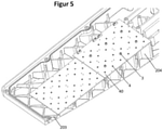
- a rib arrangement 20 is integrated in the first housing part 1 and has ribs 2 which, starting from the side wall 10 , extend vertically towards the light emission window and thus towards the upper side of the first housing part 1 .
- the ribs 2 of the rib arrangement 20 are arranged to form a regular cross-lattice pattern.
- the ribs 2 of the rib arrangement 20 intersect at crossing points 21 at which the ribs 2 merge into one another. In this case, four of the ribs 2, which cross at crossing points 21 and thereby merge into one another, enclose an intermediate space with respect to the horizontal.
- This intermediate space is horizontally closed peripherally delimited by these four ribs 2 and delimited by the side wall 10 on its vertical side opposite the light exit window.
- the intermediate space is completely closed except at its vertical end, which points towards the light exit window.
- the LEDs 4 drawn so that their positions along the horizontal can be seen. From this it follows that the LEDs 4 are arranged along the ribs 2 .
- the ribs 2 in a horizontal center area 201 which extends around the horizontal center of the light exit window, have a greater rib thickness than in a horizontal edge area 202, which is arranged horizontally on the outside of the center area 201.
- the arrangement of the LEDs 4 along the ribs 2 can ensure a particularly good heat transfer from the LEDs 4 to the ribs 2 .
- Varying the rib thickness in the different areas 201, 202 can particularly preferably promote heat dissipation from the central area 201, in which a particularly high heat development takes place, with material costs being able to be saved by providing a smaller rib thickness in the edge area 202.
- the LEDs 4 are not arranged directly on the ribs 2 but on a circuit board 40, the circuit boards 40 with the LEDs 4 and their further electrical components forming the lighting means of the described embodiment.
- This illuminant is thus placed directly on the vertical side of the ribs 2 pointing towards the light exit window and is fixed to the ribs 2 . It is fixed using screws 3 which are screwed into threaded holes 22 which are provided at at least some of the crossing points 21, which is generally particularly advantageous.
- optical elements 5 are also provided between the LEDs 4 and the light exit window, with which the light distribution emitted by the lamp can be influenced in a targeted manner. These optical elements 5 are fastened to the ribs 2 by the same fastening means, namely screws 3 and threaded bores 22, with which the circuit boards 40 are also fastened.
- the fastening means fix the at least one optical element 5 to the ribs 2, in that the optical element 5 is pressed vertically onto the light source, as a result of which the light source is pressed onto the vertical side of the ribs 2 facing the light exit window, which is generally advantageous according to the invention.
- the ribs 2 of the rib arrangement 20 have a different rib length along the vertical direction Z in different horizontal areas.
- the rib 204 has a greater extent along the vertical direction Z than the rib 203.
- the vertical extent of the ribs 2, 203, 204 changes to the extent that the vertical height of the lamp housing increases along the horizontal. This ensures that the vertical side of the ribs 2, 203, 204 facing the light exit window is at a uniform distance from the light exit window, so that all LEDs 4 have essentially the same vertical distance from the light exit window.
Landscapes
- Engineering & Computer Science (AREA)
- General Engineering & Computer Science (AREA)
- Physics & Mathematics (AREA)
- Geometry (AREA)
- Non-Portable Lighting Devices Or Systems Thereof (AREA)
- Arrangement Of Elements, Cooling, Sealing, Or The Like Of Lighting Devices (AREA)
Claims (10)
- Luminaire comprenant un boîtier de luminaire avec un espace intérieur et une fenêtre d'émission de lumière s'étendant sur une étendue horizontale, un moyen d'éclairage comprenant plusieurs LEDs (4) étant disposé dans l'espace intérieur et un corps de refroidissement étant disposé dans l'espace intérieur, sur lequel sont disposées les LED (4), le corps de refroidissement présentant un agencement de nervures (20) avec plusieurs nervures (2, 203, 204) qui s'étend à l'intérieur de l'extension horizontale de la fenêtre d'émission de lumière, les neruvres (2, 203, 204) s'appliquant chacune contre la paroi latérale (10) du boîtier de luminaire qui est opposée verticalement à la fenêtre d'émission de lumière et qui délimite l'espace intérieur, et formant entre elles des espaces intermédiaires, le moyen d'éclairage reposant sur le côté de l'agencement de nervures (20) tourné vers la fenêtre d'émission de lumière, le corps de refroidissement disposé dans l'espace intérieur étant intégré d'un seul tenant dans la paroi latérale (10) délimitant l'espace intérieur et cette paroi latérale (10) ne présentant pas de structure de nervures sur son côté extérieur, la paroi latérale (10) formant une section de fond d'une première partie de boîtier (1) ayant une forme de cuvette et la fenêtre d'émission de lumière étant entourée par une deuxième partie de boîtier réalisée sous forme de couvercle, les parties de boîtier (1) étant reliées entre elles de manière étanche en formant l'espace intérieur sous forme d'espace intérieur étanche,
caractérisé en ce que
l'agencement de nervures (20) s'étend avec une section horizontale au-delà du moyen d'éclairage, cette section horizontale de l'agencement de nervures (20) se trouvant à l'intérieur de l'extension horizontale de la fenêtre d'émission de lumière. - Luminaire selon la revendication 1,
caractérisé en ce que
les nervures (2, 203, 204) de l'agencement de nervures (20) sont disposées de manière à former un motif régulier, le motif étant notamment un motif en nid d'abeilles ou un autre motif de grille croisée. - Luminaire selon l'une quelconque des revendications précédentes,
caractérisé en ce que
les nervures (2, 203, 204) de l'agencement de -nervures (20) se croisent en des points d'intersection (21), les points d'intersection (21) formant notamment chacun les coins des espaces intermédiaires entre les nervures (2, 203, 204) et chacun des espaces intermédiaires étant entouré horizontalement sur sa circonférence par les nervures (2, 203, 204) qui le délimitent, étant fermé verticalement par la paroi latérale (10) opposée à la fenêtre d'émission de lumière et étant ouvert sur son côté vertical tourné vers la fenêtre d'émission de lumière. - Luminaire selon l'une quelconque des revendications précédentes,
caractérisé en ce que
les LEDs (4) sont disposées le long des nervures (2, 203, 204) . - Luminaire selon l'une quelconque des revendications précédentes,
caractérisé en ce que
le moyen d'éclairage, et notamment un élément optique (5) disposé entre les LEDs (4) et la fenêtre d'émission de lumière, est fixé à au moins certaines nervures (2, 203, 204) notamment par l'intermédiaire de moyens de fixation (3, 22) disposés sur une face de ces nervures (2, 203, 204) tournée vers la fenêtre d'émission de lumière. - Luminaire selon la revendication 5,
caractérisé en ce que
le moyen d'éclairage se présente sous la forme d'un PCB et est fixé directement sur au moins certaines des nervures (2, 203, 204) de l'agencement de nervures- (20) ou que le moyen d'éclairage comprend des pistes conductrices électriques qui sont appliquées directement sur au moins certaines des nervures (2, 203, 204) de l'agencement de nervures (20). - Luminaire selon l'une quelconque des revendications précédentes,
caractérisé en ce que
la partie horizontale de l'agencement de nervures (20) par laquelle il s'étend au-delà du moyen d'éclairage est visible de l'extérieur à travers la fenêtre d'émission de lumière. - Luminaire selon l'une quelconque des revendications précédentes,
caractérisé en ce que
les nervures (2, 203, 204) présentent une épaisseur de nervure et une longueur de nervure sur laquelle elles s'étendent horizontalement, des épaisseurs de nervure différentes étant respectivement prévues dans différentes sections horizontales de l'agencement de nervures (20), l'épaisseur de nervure des nervures (2, 203, 204) étant notamment plus grande dans une zone centrale horizontale (201) qui s'étend autour du centre horizontal de l'ouverture de sortie de lumière que dans une zone de bordure horizontale (202) qui est disposée horizontalement à l'extérieur de la zone centrale (201). - Luminaire selon l'une quelconque des revendications précédentes,
caractérisé en ce que
le boîtier de luminaire présente une hauteur verticale qui varie à l'intérieur d'une zone d'extension horizontale de l'agencement de nervures (20), une extension verticale des nervures (2, 203, 204) de l'agencement de nervures (20) augmentant à l'intérieur de cette zone dans la même mesure que la hauteur verticale du boîtier de luminaire, de sorte qu'un côté de l'agencement de nervures (20) tourné vers la fenêtre d'émission de lumière, qui est formé par le côté des nervures (2, 203, 204) tourné vers la fenêtre d'émission de lumière, présente une distance constante par rapport à la fenêtre d'émission de lumière à l'intérieur de cette zone. - Luminaire selon l'une quelconque des revendications précédentes,
caractérisé en ce que
la paroi latérale (10) est fabriquée d'une seule pièce avec l'agencement de nervures (20), en particulier la première partie de boîtier (1) en forme de cuvette, au moyen d'un procédé de coulée, en particulier un procédé de coulée de métal.
Applications Claiming Priority (1)
| Application Number | Priority Date | Filing Date | Title |
|---|---|---|---|
| DE102018133500.8A DE102018133500A1 (de) | 2018-12-21 | 2018-12-21 | Leuchte mit Kühlrippen im Leuchtengehäuse |
Publications (2)
| Publication Number | Publication Date |
|---|---|
| EP3671035A1 EP3671035A1 (fr) | 2020-06-24 |
| EP3671035B1 true EP3671035B1 (fr) | 2022-02-09 |
Family
ID=69411055
Family Applications (1)
| Application Number | Title | Priority Date | Filing Date |
|---|---|---|---|
| EP19218415.8A Active EP3671035B1 (fr) | 2018-12-21 | 2019-12-20 | Luminaire pourvu de nervures de refroidissement dans le boîtier de luminaire |
Country Status (2)
| Country | Link |
|---|---|
| EP (1) | EP3671035B1 (fr) |
| DE (1) | DE102018133500A1 (fr) |
Families Citing this family (1)
| Publication number | Priority date | Publication date | Assignee | Title |
|---|---|---|---|---|
| EP4522064A1 (fr) * | 2023-07-28 | 2025-03-19 | KaVo Dental GmbH | Lampe médicale |
Citations (10)
| Publication number | Priority date | Publication date | Assignee | Title |
|---|---|---|---|---|
| JPH05206339A (ja) | 1992-01-27 | 1993-08-13 | Matsushita Electric Ind Co Ltd | 放熱器 |
| CN201487718U (zh) | 2009-09-03 | 2010-05-26 | 黄金鹿 | 一种折射反射配光一体化led路灯 |
| CN201935071U (zh) | 2011-01-19 | 2011-08-17 | 昆山华英光宝科技有限公司 | 网拍式路灯 |
| DE102010054592A1 (de) | 2010-12-15 | 2012-06-21 | Autev Ag | Kühlvorrichtung zum Kühlen von Bauteilen |
| CN203024030U (zh) | 2012-11-14 | 2013-06-26 | 厦门飞华隆智能科技有限公司 | 大功率太阳能led路灯头 |
| DE202013102667U1 (de) | 2013-06-20 | 2013-07-09 | Stührenberg GmbH Elektrobau-Signaltechnik | Lampengehäuse mit Wärmeableitungsstruktur |
| EP2779652A1 (fr) | 2013-03-14 | 2014-09-17 | ABL IP Holding LLC | Commande de zone voilée |
| CN204922732U (zh) | 2015-07-16 | 2015-12-30 | 湖南亚珺光电科技有限公司 | 一种空气高效净化路灯 |
| KR101727908B1 (ko) | 2015-02-03 | 2017-04-18 | 엘지전자 주식회사 | 가로등용 조명장치 |
| WO2018214804A1 (fr) * | 2017-05-25 | 2018-11-29 | 苏州欧普照明有限公司 | Lampe |
Family Cites Families (6)
| Publication number | Priority date | Publication date | Assignee | Title |
|---|---|---|---|---|
| US8465178B2 (en) * | 2010-09-07 | 2013-06-18 | Cree, Inc. | LED lighting fixture |
| KR101000014B1 (ko) * | 2010-10-11 | 2010-12-09 | 주식회사 금영 | 엘이디 가로등 장치 |
| TWM423207U (en) * | 2011-10-13 | 2012-02-21 | Yi-Ming Chen | Heat-dissipation structure for light bulb |
| KR101376079B1 (ko) * | 2013-12-23 | 2014-03-19 | 주식회사 금영 | 엘이디 보안등 |
| CA2950283C (fr) * | 2014-05-30 | 2023-09-05 | Hubbell Incorporated | Luminaire d'eclairage de zone dote d'ailettes thermiques |
| CA2971938C (fr) * | 2017-01-16 | 2025-09-16 | Lumca Inc. | Appareil d'eclairage del |
-
2018
- 2018-12-21 DE DE102018133500.8A patent/DE102018133500A1/de active Pending
-
2019
- 2019-12-20 EP EP19218415.8A patent/EP3671035B1/fr active Active
Patent Citations (10)
| Publication number | Priority date | Publication date | Assignee | Title |
|---|---|---|---|---|
| JPH05206339A (ja) | 1992-01-27 | 1993-08-13 | Matsushita Electric Ind Co Ltd | 放熱器 |
| CN201487718U (zh) | 2009-09-03 | 2010-05-26 | 黄金鹿 | 一种折射反射配光一体化led路灯 |
| DE102010054592A1 (de) | 2010-12-15 | 2012-06-21 | Autev Ag | Kühlvorrichtung zum Kühlen von Bauteilen |
| CN201935071U (zh) | 2011-01-19 | 2011-08-17 | 昆山华英光宝科技有限公司 | 网拍式路灯 |
| CN203024030U (zh) | 2012-11-14 | 2013-06-26 | 厦门飞华隆智能科技有限公司 | 大功率太阳能led路灯头 |
| EP2779652A1 (fr) | 2013-03-14 | 2014-09-17 | ABL IP Holding LLC | Commande de zone voilée |
| DE202013102667U1 (de) | 2013-06-20 | 2013-07-09 | Stührenberg GmbH Elektrobau-Signaltechnik | Lampengehäuse mit Wärmeableitungsstruktur |
| KR101727908B1 (ko) | 2015-02-03 | 2017-04-18 | 엘지전자 주식회사 | 가로등용 조명장치 |
| CN204922732U (zh) | 2015-07-16 | 2015-12-30 | 湖南亚珺光电科技有限公司 | 一种空气高效净化路灯 |
| WO2018214804A1 (fr) * | 2017-05-25 | 2018-11-29 | 苏州欧普照明有限公司 | Lampe |
Non-Patent Citations (1)
| Title |
|---|
| PRYDE JAMES R: "Development of effective thermal management strategies for led luminaires", A DOCTORAL THESIS, WOLFSON SCHOOL OF MECHANICAL AND MANUFACTURING ENGINEERING, PROQUEST DISSERTATIONS PUBLISHING, 1 September 2017 (2017-09-01), pages 1 - 21, XP093092880 |
Also Published As
| Publication number | Publication date |
|---|---|
| DE102018133500A1 (de) | 2020-06-25 |
| EP3671035A1 (fr) | 2020-06-24 |
Similar Documents
| Publication | Publication Date | Title |
|---|---|---|
| DE102013216275B4 (de) | Leuchte | |
| DE102009014536A1 (de) | Träger mit mindestens einer Halbleiterleuchtvorrichtung und Trägersystem | |
| DE102009060434B4 (de) | Geschlossene LED-Leuchte mit thermischem Koppelelement | |
| DE102018117378A1 (de) | Leistungsversorgung, Lampe, bewegliche Vorrichtung und Verfahren zur Herstellung einer Leistungsversorgung | |
| DE4028000A1 (de) | Gehaeuse | |
| DE102009016256A1 (de) | Außenraum-Beleuchtungseinheit | |
| EP2322847B1 (fr) | Plafonnier réglable à DEL | |
| WO2009033477A1 (fr) | Dispositif d'éclairage | |
| EP2273185B1 (fr) | Eléments d'éclairage à DEL dotés d'un élément de guidage de la lumière | |
| EP2924334A1 (fr) | Lampadaire à technologie LED | |
| EP3671035A1 (fr) | Luminaire pourvu de nervures de refroidissement dans le boîtier de luminaire | |
| DE202012103474U1 (de) | LED-Leuchte | |
| DE20120770U1 (de) | Oberflächenmontierte LED-Mehrfachanordnung und Beleuchtungseinrichtung damit | |
| EP3399225B1 (fr) | Luminaire de tunnel | |
| AT509626B1 (de) | Modulares led beleuchtungssystem mit partieller lichtstärkenanpassung | |
| DE102009050700B4 (de) | LED-Leuchte sowie System | |
| WO2017153129A1 (fr) | Dispositif d'éclairage pour éclairage uniforme | |
| EP2244003A1 (fr) | Eclairage de route | |
| WO2016058570A1 (fr) | Éclairage de rue à led | |
| EP2581657B1 (fr) | Agencement de corps de refroidissement pour une lampe à DEL ainsi que la lampe à DEL | |
| EP3686481B1 (fr) | Dissipateur thermique pour une platine del | |
| DE102017109836B4 (de) | Leuchtmittel mit Kühlkörper | |
| EP3446031B1 (fr) | Appareil d'éclairage d'armoire de distribution pourvu d'une platine à source lumineuse réglable | |
| EP2532955A2 (fr) | Lampe à diodes électroluminescentes et circuit de commande d'une source lumineuse | |
| EP3218648B1 (fr) | Lampe à led pourvue d'un guide de lumière coudé |
Legal Events
| Date | Code | Title | Description |
|---|---|---|---|
| PUAI | Public reference made under article 153(3) epc to a published international application that has entered the european phase |
Free format text: ORIGINAL CODE: 0009012 |
|
| STAA | Information on the status of an ep patent application or granted ep patent |
Free format text: STATUS: THE APPLICATION HAS BEEN PUBLISHED |
|
| AK | Designated contracting states |
Kind code of ref document: A1 Designated state(s): AL AT BE BG CH CY CZ DE DK EE ES FI FR GB GR HR HU IE IS IT LI LT LU LV MC MK MT NL NO PL PT RO RS SE SI SK SM TR |
|
| AX | Request for extension of the european patent |
Extension state: BA ME |
|
| STAA | Information on the status of an ep patent application or granted ep patent |
Free format text: STATUS: REQUEST FOR EXAMINATION WAS MADE |
|
| 17P | Request for examination filed |
Effective date: 20210111 |
|
| RBV | Designated contracting states (corrected) |
Designated state(s): AL AT BE BG CH CY CZ DE DK EE ES FI FR GB GR HR HU IE IS IT LI LT LU LV MC MK MT NL NO PL PT RO RS SE SI SK SM TR |
|
| STAA | Information on the status of an ep patent application or granted ep patent |
Free format text: STATUS: EXAMINATION IS IN PROGRESS |
|
| 17Q | First examination report despatched |
Effective date: 20210319 |
|
| GRAP | Despatch of communication of intention to grant a patent |
Free format text: ORIGINAL CODE: EPIDOSNIGR1 |
|
| STAA | Information on the status of an ep patent application or granted ep patent |
Free format text: STATUS: GRANT OF PATENT IS INTENDED |
|
| RIC1 | Information provided on ipc code assigned before grant |
Ipc: F21Y 105/16 20160101ALN20211108BHEP Ipc: F21Y 115/10 20160101ALN20211108BHEP Ipc: F21W 131/103 20060101ALN20211108BHEP Ipc: F21V 5/00 20180101ALN20211108BHEP Ipc: F21V 15/01 20060101ALI20211108BHEP Ipc: F21V 29/75 20150101AFI20211108BHEP |
|
| INTG | Intention to grant announced |
Effective date: 20211126 |
|
| RIC1 | Information provided on ipc code assigned before grant |
Ipc: F21Y 105/16 20160101ALN20211118BHEP Ipc: F21Y 115/10 20160101ALN20211118BHEP Ipc: F21W 131/103 20060101ALN20211118BHEP Ipc: F21V 5/00 20180101ALN20211118BHEP Ipc: F21V 15/01 20060101ALI20211118BHEP Ipc: F21V 29/75 20150101AFI20211118BHEP |
|
| GRAS | Grant fee paid |
Free format text: ORIGINAL CODE: EPIDOSNIGR3 |
|
| GRAA | (expected) grant |
Free format text: ORIGINAL CODE: 0009210 |
|
| STAA | Information on the status of an ep patent application or granted ep patent |
Free format text: STATUS: THE PATENT HAS BEEN GRANTED |
|
| AK | Designated contracting states |
Kind code of ref document: B1 Designated state(s): AL AT BE BG CH CY CZ DE DK EE ES FI FR GB GR HR HU IE IS IT LI LT LU LV MC MK MT NL NO PL PT RO RS SE SI SK SM TR |
|
| REG | Reference to a national code |
Ref country code: GB Ref legal event code: FG4D Free format text: NOT ENGLISH |
|
| REG | Reference to a national code |
Ref country code: CH Ref legal event code: EP Ref country code: AT Ref legal event code: REF Ref document number: 1467729 Country of ref document: AT Kind code of ref document: T Effective date: 20220215 |
|
| REG | Reference to a national code |
Ref country code: DE Ref legal event code: R096 Ref document number: 502019003403 Country of ref document: DE |
|
| REG | Reference to a national code |
Ref country code: IE Ref legal event code: FG4D Free format text: LANGUAGE OF EP DOCUMENT: GERMAN |
|
| REG | Reference to a national code |
Ref country code: LT Ref legal event code: MG9D |
|
| REG | Reference to a national code |
Ref country code: NL Ref legal event code: MP Effective date: 20220209 |
|
| PG25 | Lapsed in a contracting state [announced via postgrant information from national office to epo] |
Ref country code: SE Free format text: LAPSE BECAUSE OF FAILURE TO SUBMIT A TRANSLATION OF THE DESCRIPTION OR TO PAY THE FEE WITHIN THE PRESCRIBED TIME-LIMIT Effective date: 20220209 Ref country code: RS Free format text: LAPSE BECAUSE OF FAILURE TO SUBMIT A TRANSLATION OF THE DESCRIPTION OR TO PAY THE FEE WITHIN THE PRESCRIBED TIME-LIMIT Effective date: 20220209 Ref country code: PT Free format text: LAPSE BECAUSE OF FAILURE TO SUBMIT A TRANSLATION OF THE DESCRIPTION OR TO PAY THE FEE WITHIN THE PRESCRIBED TIME-LIMIT Effective date: 20220609 Ref country code: NO Free format text: LAPSE BECAUSE OF FAILURE TO SUBMIT A TRANSLATION OF THE DESCRIPTION OR TO PAY THE FEE WITHIN THE PRESCRIBED TIME-LIMIT Effective date: 20220509 Ref country code: NL Free format text: LAPSE BECAUSE OF FAILURE TO SUBMIT A TRANSLATION OF THE DESCRIPTION OR TO PAY THE FEE WITHIN THE PRESCRIBED TIME-LIMIT Effective date: 20220209 Ref country code: LT Free format text: LAPSE BECAUSE OF FAILURE TO SUBMIT A TRANSLATION OF THE DESCRIPTION OR TO PAY THE FEE WITHIN THE PRESCRIBED TIME-LIMIT Effective date: 20220209 Ref country code: HR Free format text: LAPSE BECAUSE OF FAILURE TO SUBMIT A TRANSLATION OF THE DESCRIPTION OR TO PAY THE FEE WITHIN THE PRESCRIBED TIME-LIMIT Effective date: 20220209 Ref country code: ES Free format text: LAPSE BECAUSE OF FAILURE TO SUBMIT A TRANSLATION OF THE DESCRIPTION OR TO PAY THE FEE WITHIN THE PRESCRIBED TIME-LIMIT Effective date: 20220209 Ref country code: BG Free format text: LAPSE BECAUSE OF FAILURE TO SUBMIT A TRANSLATION OF THE DESCRIPTION OR TO PAY THE FEE WITHIN THE PRESCRIBED TIME-LIMIT Effective date: 20220509 |
|
| PG25 | Lapsed in a contracting state [announced via postgrant information from national office to epo] |
Ref country code: PL Free format text: LAPSE BECAUSE OF FAILURE TO SUBMIT A TRANSLATION OF THE DESCRIPTION OR TO PAY THE FEE WITHIN THE PRESCRIBED TIME-LIMIT Effective date: 20220209 Ref country code: LV Free format text: LAPSE BECAUSE OF FAILURE TO SUBMIT A TRANSLATION OF THE DESCRIPTION OR TO PAY THE FEE WITHIN THE PRESCRIBED TIME-LIMIT Effective date: 20220209 Ref country code: GR Free format text: LAPSE BECAUSE OF FAILURE TO SUBMIT A TRANSLATION OF THE DESCRIPTION OR TO PAY THE FEE WITHIN THE PRESCRIBED TIME-LIMIT Effective date: 20220510 Ref country code: FI Free format text: LAPSE BECAUSE OF FAILURE TO SUBMIT A TRANSLATION OF THE DESCRIPTION OR TO PAY THE FEE WITHIN THE PRESCRIBED TIME-LIMIT Effective date: 20220209 |
|
| PG25 | Lapsed in a contracting state [announced via postgrant information from national office to epo] |
Ref country code: IS Free format text: LAPSE BECAUSE OF FAILURE TO SUBMIT A TRANSLATION OF THE DESCRIPTION OR TO PAY THE FEE WITHIN THE PRESCRIBED TIME-LIMIT Effective date: 20220609 |
|
| PG25 | Lapsed in a contracting state [announced via postgrant information from national office to epo] |
Ref country code: SM Free format text: LAPSE BECAUSE OF FAILURE TO SUBMIT A TRANSLATION OF THE DESCRIPTION OR TO PAY THE FEE WITHIN THE PRESCRIBED TIME-LIMIT Effective date: 20220209 Ref country code: SK Free format text: LAPSE BECAUSE OF FAILURE TO SUBMIT A TRANSLATION OF THE DESCRIPTION OR TO PAY THE FEE WITHIN THE PRESCRIBED TIME-LIMIT Effective date: 20220209 Ref country code: RO Free format text: LAPSE BECAUSE OF FAILURE TO SUBMIT A TRANSLATION OF THE DESCRIPTION OR TO PAY THE FEE WITHIN THE PRESCRIBED TIME-LIMIT Effective date: 20220209 Ref country code: EE Free format text: LAPSE BECAUSE OF FAILURE TO SUBMIT A TRANSLATION OF THE DESCRIPTION OR TO PAY THE FEE WITHIN THE PRESCRIBED TIME-LIMIT Effective date: 20220209 Ref country code: DK Free format text: LAPSE BECAUSE OF FAILURE TO SUBMIT A TRANSLATION OF THE DESCRIPTION OR TO PAY THE FEE WITHIN THE PRESCRIBED TIME-LIMIT Effective date: 20220209 Ref country code: CZ Free format text: LAPSE BECAUSE OF FAILURE TO SUBMIT A TRANSLATION OF THE DESCRIPTION OR TO PAY THE FEE WITHIN THE PRESCRIBED TIME-LIMIT Effective date: 20220209 |
|
| REG | Reference to a national code |
Ref country code: DE Ref legal event code: R026 Ref document number: 502019003403 Country of ref document: DE |
|
| PLBI | Opposition filed |
Free format text: ORIGINAL CODE: 0009260 |
|
| PLAB | Opposition data, opponent's data or that of the opponent's representative modified |
Free format text: ORIGINAL CODE: 0009299OPPO |
|
| PG25 | Lapsed in a contracting state [announced via postgrant information from national office to epo] |
Ref country code: AL Free format text: LAPSE BECAUSE OF FAILURE TO SUBMIT A TRANSLATION OF THE DESCRIPTION OR TO PAY THE FEE WITHIN THE PRESCRIBED TIME-LIMIT Effective date: 20220209 |
|
| PLAX | Notice of opposition and request to file observation + time limit sent |
Free format text: ORIGINAL CODE: EPIDOSNOBS2 |
|
| 26 | Opposition filed |
Opponent name: SCHOEPF, PATRICK Effective date: 20221109 |
|
| R26 | Opposition filed (corrected) |
Opponent name: SCHOEPF, PATRICK Effective date: 20221109 |
|
| PG25 | Lapsed in a contracting state [announced via postgrant information from national office to epo] |
Ref country code: SI Free format text: LAPSE BECAUSE OF FAILURE TO SUBMIT A TRANSLATION OF THE DESCRIPTION OR TO PAY THE FEE WITHIN THE PRESCRIBED TIME-LIMIT Effective date: 20220209 |
|
| PLBB | Reply of patent proprietor to notice(s) of opposition received |
Free format text: ORIGINAL CODE: EPIDOSNOBS3 |
|
| P01 | Opt-out of the competence of the unified patent court (upc) registered |
Effective date: 20230527 |
|
| PG25 | Lapsed in a contracting state [announced via postgrant information from national office to epo] |
Ref country code: IT Free format text: LAPSE BECAUSE OF FAILURE TO SUBMIT A TRANSLATION OF THE DESCRIPTION OR TO PAY THE FEE WITHIN THE PRESCRIBED TIME-LIMIT Effective date: 20220209 |
|
| PG25 | Lapsed in a contracting state [announced via postgrant information from national office to epo] |
Ref country code: LU Free format text: LAPSE BECAUSE OF NON-PAYMENT OF DUE FEES Effective date: 20221220 |
|
| PG25 | Lapsed in a contracting state [announced via postgrant information from national office to epo] |
Ref country code: IE Free format text: LAPSE BECAUSE OF NON-PAYMENT OF DUE FEES Effective date: 20221220 |
|
| PG25 | Lapsed in a contracting state [announced via postgrant information from national office to epo] |
Ref country code: HU Free format text: LAPSE BECAUSE OF FAILURE TO SUBMIT A TRANSLATION OF THE DESCRIPTION OR TO PAY THE FEE WITHIN THE PRESCRIBED TIME-LIMIT; INVALID AB INITIO Effective date: 20191220 |
|
| PG25 | Lapsed in a contracting state [announced via postgrant information from national office to epo] |
Ref country code: CY Free format text: LAPSE BECAUSE OF FAILURE TO SUBMIT A TRANSLATION OF THE DESCRIPTION OR TO PAY THE FEE WITHIN THE PRESCRIBED TIME-LIMIT Effective date: 20220209 |
|
| PG25 | Lapsed in a contracting state [announced via postgrant information from national office to epo] |
Ref country code: MK Free format text: LAPSE BECAUSE OF FAILURE TO SUBMIT A TRANSLATION OF THE DESCRIPTION OR TO PAY THE FEE WITHIN THE PRESCRIBED TIME-LIMIT Effective date: 20220209 |
|
| PG25 | Lapsed in a contracting state [announced via postgrant information from national office to epo] |
Ref country code: MC Free format text: LAPSE BECAUSE OF FAILURE TO SUBMIT A TRANSLATION OF THE DESCRIPTION OR TO PAY THE FEE WITHIN THE PRESCRIBED TIME-LIMIT Effective date: 20220209 |
|
| PG25 | Lapsed in a contracting state [announced via postgrant information from national office to epo] |
Ref country code: MC Free format text: LAPSE BECAUSE OF FAILURE TO SUBMIT A TRANSLATION OF THE DESCRIPTION OR TO PAY THE FEE WITHIN THE PRESCRIBED TIME-LIMIT Effective date: 20220209 |
|
| PG25 | Lapsed in a contracting state [announced via postgrant information from national office to epo] |
Ref country code: MT Free format text: LAPSE BECAUSE OF FAILURE TO SUBMIT A TRANSLATION OF THE DESCRIPTION OR TO PAY THE FEE WITHIN THE PRESCRIBED TIME-LIMIT Effective date: 20220209 |
|
| APBP | Date of receipt of notice of appeal recorded |
Free format text: ORIGINAL CODE: EPIDOSNNOA2O |
|
| APAH | Appeal reference modified |
Free format text: ORIGINAL CODE: EPIDOSCREFNO |
|
| APAW | Appeal reference deleted |
Free format text: ORIGINAL CODE: EPIDOSDREFNO |
|
| APBP | Date of receipt of notice of appeal recorded |
Free format text: ORIGINAL CODE: EPIDOSNNOA2O |
|
| APBQ | Date of receipt of statement of grounds of appeal recorded |
Free format text: ORIGINAL CODE: EPIDOSNNOA3O |
|
| PG25 | Lapsed in a contracting state [announced via postgrant information from national office to epo] |
Ref country code: TR Free format text: LAPSE BECAUSE OF FAILURE TO SUBMIT A TRANSLATION OF THE DESCRIPTION OR TO PAY THE FEE WITHIN THE PRESCRIBED TIME-LIMIT Effective date: 20220209 |
|
| REG | Reference to a national code |
Ref country code: CH Ref legal event code: U11 Free format text: ST27 STATUS EVENT CODE: U-0-0-U10-U11 (AS PROVIDED BY THE NATIONAL OFFICE) Effective date: 20260101 |
|
| PGFP | Annual fee paid to national office [announced via postgrant information from national office to epo] |
Ref country code: GB Payment date: 20251218 Year of fee payment: 7 |
|
| PGFP | Annual fee paid to national office [announced via postgrant information from national office to epo] |
Ref country code: AT Payment date: 20251215 Year of fee payment: 7 |
|
| PGFP | Annual fee paid to national office [announced via postgrant information from national office to epo] |
Ref country code: FR Payment date: 20251217 Year of fee payment: 7 |
|
| PGFP | Annual fee paid to national office [announced via postgrant information from national office to epo] |
Ref country code: BE Payment date: 20251223 Year of fee payment: 7 |
|
| APBU | Appeal procedure closed |
Free format text: ORIGINAL CODE: EPIDOSNNOA9O |
|
| PGFP | Annual fee paid to national office [announced via postgrant information from national office to epo] |
Ref country code: DE Payment date: 20260225 Year of fee payment: 7 |
|
| PGFP | Annual fee paid to national office [announced via postgrant information from national office to epo] |
Ref country code: CH Payment date: 20260101 Year of fee payment: 7 |