EP3671107A1 - Dehnungsmessstreifenkrümmungsmesswerkzeug zur 3d-präzisionspositionskontrolle von dünnen folien - Google Patents
Dehnungsmessstreifenkrümmungsmesswerkzeug zur 3d-präzisionspositionskontrolle von dünnen folien Download PDFInfo
- Publication number
- EP3671107A1 EP3671107A1 EP18213819.8A EP18213819A EP3671107A1 EP 3671107 A1 EP3671107 A1 EP 3671107A1 EP 18213819 A EP18213819 A EP 18213819A EP 3671107 A1 EP3671107 A1 EP 3671107A1
- Authority
- EP
- European Patent Office
- Prior art keywords
- strain gauge
- gauge sensors
- conductive film
- matrix
- thin conductive
- Prior art date
- Legal status (The legal status is an assumption and is not a legal conclusion. Google has not performed a legal analysis and makes no representation as to the accuracy of the status listed.)
- Withdrawn
Links
- 238000005259 measurement Methods 0.000 title claims abstract description 36
- 239000011888 foil Substances 0.000 title claims description 15
- 239000011159 matrix material Substances 0.000 claims abstract description 79
- 239000000758 substrate Substances 0.000 claims abstract description 46
- 239000010408 film Substances 0.000 claims description 50
- 229920000139 polyethylene terephthalate Polymers 0.000 claims description 19
- 239000005020 polyethylene terephthalate Substances 0.000 claims description 18
- 238000005530 etching Methods 0.000 claims description 10
- 238000000034 method Methods 0.000 claims description 8
- 239000010409 thin film Substances 0.000 claims description 7
- -1 polyethylene terephthalate Polymers 0.000 claims description 6
- 238000004519 manufacturing process Methods 0.000 claims description 2
- 238000002600 positron emission tomography Methods 0.000 claims description 2
- XLYOFNOQVPJJNP-UHFFFAOYSA-N water Substances O XLYOFNOQVPJJNP-UHFFFAOYSA-N 0.000 claims description 2
- 239000000835 fiber Substances 0.000 description 6
- 239000013598 vector Substances 0.000 description 6
- 230000006835 compression Effects 0.000 description 4
- 238000007906 compression Methods 0.000 description 4
- 230000000694 effects Effects 0.000 description 4
- 230000009466 transformation Effects 0.000 description 3
- 239000004020 conductor Substances 0.000 description 2
- 238000006073 displacement reaction Methods 0.000 description 2
- 230000010354 integration Effects 0.000 description 2
- 230000003068 static effect Effects 0.000 description 2
- 239000012876 carrier material Substances 0.000 description 1
- 238000009826 distribution Methods 0.000 description 1
- 239000000463 material Substances 0.000 description 1
- 238000000691 measurement method Methods 0.000 description 1
- 230000007935 neutral effect Effects 0.000 description 1
- 230000000399 orthopedic effect Effects 0.000 description 1
- 238000005240 physical vapour deposition Methods 0.000 description 1
- 239000004033 plastic Substances 0.000 description 1
- 229920003023 plastic Polymers 0.000 description 1
- 229910052709 silver Inorganic materials 0.000 description 1
- 239000004332 silver Substances 0.000 description 1
- 239000007787 solid Substances 0.000 description 1
Images


Classifications
-
- G—PHYSICS
- G01—MEASURING; TESTING
- G01B—MEASURING LENGTH, THICKNESS OR SIMILAR LINEAR DIMENSIONS; MEASURING ANGLES; MEASURING AREAS; MEASURING IRREGULARITIES OF SURFACES OR CONTOURS
- G01B7/00—Measuring arrangements characterised by the use of electric or magnetic techniques
- G01B7/16—Measuring arrangements characterised by the use of electric or magnetic techniques for measuring the deformation in a solid, e.g. by resistance strain gauge
- G01B7/18—Measuring arrangements characterised by the use of electric or magnetic techniques for measuring the deformation in a solid, e.g. by resistance strain gauge using change in resistance
- G01B7/20—Measuring arrangements characterised by the use of electric or magnetic techniques for measuring the deformation in a solid, e.g. by resistance strain gauge using change in resistance formed by printed-circuit technique
-
- G—PHYSICS
- G01—MEASURING; TESTING
- G01B—MEASURING LENGTH, THICKNESS OR SIMILAR LINEAR DIMENSIONS; MEASURING ANGLES; MEASURING AREAS; MEASURING IRREGULARITIES OF SURFACES OR CONTOURS
- G01B7/00—Measuring arrangements characterised by the use of electric or magnetic techniques
- G01B7/28—Measuring arrangements characterised by the use of electric or magnetic techniques for measuring contours or curvatures
- G01B7/287—Measuring arrangements characterised by the use of electric or magnetic techniques for measuring contours or curvatures using a plurality of fixed, simultaneously operating transducers
-
- G—PHYSICS
- G01—MEASURING; TESTING
- G01L—MEASURING FORCE, STRESS, TORQUE, WORK, MECHANICAL POWER, MECHANICAL EFFICIENCY, OR FLUID PRESSURE
- G01L1/00—Measuring force or stress, in general
- G01L1/20—Measuring force or stress, in general by measuring variations in ohmic resistance of solid materials or of electrically-conductive fluids; by making use of electrokinetic cells, i.e. liquid-containing cells wherein an electrical potential is produced or varied upon the application of stress
- G01L1/205—Measuring force or stress, in general by measuring variations in ohmic resistance of solid materials or of electrically-conductive fluids; by making use of electrokinetic cells, i.e. liquid-containing cells wherein an electrical potential is produced or varied upon the application of stress using distributed sensing elements
-
- G—PHYSICS
- G01—MEASURING; TESTING
- G01L—MEASURING FORCE, STRESS, TORQUE, WORK, MECHANICAL POWER, MECHANICAL EFFICIENCY, OR FLUID PRESSURE
- G01L5/00—Apparatus for, or methods of, measuring force, work, mechanical power, or torque, specially adapted for specific purposes
- G01L5/16—Apparatus for, or methods of, measuring force, work, mechanical power, or torque, specially adapted for specific purposes for measuring several components of force
- G01L5/161—Apparatus for, or methods of, measuring force, work, mechanical power, or torque, specially adapted for specific purposes for measuring several components of force using variations in ohmic resistance
Definitions
- the present invention relates to the field of strain gauge sensors, SGS.
- strain gauge sensors are primarily used to measure small displacements in solid mechanic components such as rods and beams, and transform this data to stress. With the assumption, that for small deflections the curvature of the surface is negligible and applying Hook's Law with known Young's modulus, this measurement is quite precise with an accuracy of ⁇ 1%.
- Strain Gauge Sensors exploit that the specific resistance changes with length variation of the conductor. Therefore, a conductor in meander like form is applied to a surface, to measure its length variation, but the signal of the resistance variation is amplified by the number of loops.
- strain gauge sensors systems that are able to simultaneously measure stress in multiple directions; pull, shear and torsion. This is commonly used in high precision tools in mills to sense part edges and surfaces on specific points.
- pull, shear and torsion This is commonly used in high precision tools in mills to sense part edges and surfaces on specific points.
- One example is given by.
- the present invention provides a solution to the above-mentioned limitations and problems.
- the invention provides a strain gauge measurement blanket comprising: a substrate having an upper surface and a lower surface; a plurality of matrices of strain gauge sensors provided on the substrate; each matrix having a plurality of strain gauge sensors, all strain gauge sensors within one matrix being aligned into the same direction, respectively; said plurality of matrices of strain gauge sensors including at least a first, a second, a third and a fourth matrix of strain gauge sensors; the first and the second matrix of strain gauge sensors layered directly on top of each other and being provided directly on the upper surface of the substrate; the third and the fourth matrix of strain gauge sensors layered directly on top of each other and being provided directly on the lower surface the substrate; the strain gauge sensors of the first matrix being oriented perpendicular to the strain gauge sensors of the second matrix; the strain gauge sensors of the third matrix being oriented perpendicular to the strain gauge sensors of the fourth matrix.
- a typical known strain gauge comprises a rather long, thin conductive strip in a meander-like pattern of parallel lines.
- the direction indicated by said parallel lines, i.e. the direction parallel to said lines should be understood as the main direction of the strain gauge or just the direction of the strain gauge. This direction typically also coincides with that end of the strain gauge where electrodes are provided for reading out the strain gauge.
- the blanket comprises two matrices of strain gauge sensors wherein within each matrix the strain gauge sensors are all oriented into the same direction, wherein the direction should be understood as described above.
- the two matrices of strain gauge sensors may also be viewed as a pair of strain gauge sensors.
- the term matrix should indicate a thin film or layer on which strain gauge sensors are provided in a matrix-like, grid-like, or array-like fashion, i.e. in some regular pattern following the surface of said layer.
- the strain gauge sensors of the first matrix say the lower matrix
- Said pair of matrices is provided on one surface; say the upper surface of a substrate.
- a second pair of matrices comprises a third and a fourth matrix of strain gauge sensors. Said second pair is provided on the other surface of the substrate, i.e. in case the first pair was provided on the upper surface, the second pair is provided on the lower surface of the substrate and vice versa.
- the strain gauge sensors of the third matrix are oriented perpendicular to the strain gauge sensors of the fourth matrix. Within the respective matrix, the strain gauge sensors are oriented into the same direction.
- strain gauge sensors within one matrix are for example the same; in particular, the strain gauge sensors of all matrices are for example the same.
- the strain gauge sensors may be well-known strain gauge sensors of one predefined size.
- strain gauge sensors of each matrix may be adjacently arranged.
- strain gauge sensors of each matrix therefore do not overlap but may be adjacently arranged. Thereby the best coverage of on layer of thin film is accomplished.
- the substrate is a polyethylene terephthalate, PET, foil, in particular the PET foil having a stiffness of tensile modulus -1000-10000 MPa.
- a PET substrate is easily available and together with the two pairs of matrices as described above, it forms a light and flexible blanket which may be applicable to measure the curvature of curved surfaces by overlaying the blanket on the curvature to be measured.
- the invention further provides a system for curvature measurement comprising a strain gauge measurement blanket as described above, a multiplexer connected to the sensors of the strain gauge measurement blanket; a resistance meter connected to the multiplexer; a control unit connected to the resistance meter; and a clock connected at least to the control unit and the multiplexer.
- the system includes the strain gauge measurement blanket together with equipment for measuring the curvature.
- the system may be configured to conduct the curvature measurement using the strain gauge measurement blanket in real-time.
- correction parameters for curvature e.g. correction of distortion, correction of pressure etc. may be calculate also in real-time since the measurement data is available in real time.
- the system may be configured to be integrated into one or more of a flexible display of a mobile device such as a smartphone, a mobile phone, a tablet, a phablet, a mobile computer, a virtual reality, VR, control, a water bed mattress with active pressure compensation, or a portable positron emission tomography scanner.
- a mobile device such as a smartphone, a mobile phone, a tablet, a phablet, a mobile computer, a virtual reality, VR, control, a water bed mattress with active pressure compensation, or a portable positron emission tomography scanner.
- the substrate may be part of the flexible display.
- the blanket may be placed directly onto an object of which a curvature should be quickly determined.
- the substrate may be integrated into a respective device such as a mobile device, etc. as listed above. Thereby, the blanket becomes a part of said mobile device etc.
- the substrate may be part of a flexible display to measure and to correct the curvature and thereby curvature induced distortions of said display.
- the invention further provides a method of manufacturing a strain gauge measurement blanket comprising the steps of:
- the strain gauge sensors within one thin conductive film may be the same, in particular all of the strain gauge sensors may be the same.
- the strain gauge sensors within each thin conductive film may be adjacently arranged.
- the substrate may be a polyethylene terephthalate, PET, foil, in particular the PET foil having a stiffness of tensile modulus -1000-10000 MPa.
- the method as described above may further comprise the step of providing further thin conductive films on the upper surface and/or on the lower surface of the substrate, and etching a plurality of strain gauge sensors into the respective thin conductive film in a matrix; all of said strain gauge sensors within the respective conductive film being aligned into the same direction, respectively; wherein the strain gauge sensors of one further thin conductive film may be oriented perpendicular to the strain gauge sensor of another thin conductive film directly underneath the further conductive film.
- Figure 1A illustrates a schematic view of a common strain gauge sensor 100.
- the strain gauge sensor 100 comprises a plurality of thin readout lines L on a thin film. All of said readout lines L of Fig. 1A are aligned to be substantially parallel to direction d1 indicated in Fig. 1A . Said readout lines L all have substantially the same length. Perpendicular to direction d1 the readout lines L are provided in a meander-like shape extending along direction d2 . Further, Fig. 1A illustrates readout tabs or electrodes E1 and E2, which are also provided along the direction d1. That is, the readout direction of the strain gauge sensor 100 of Fig. 1 is the same as the direction to which the readout lines L are oriented.
- Figure 1B shows a schematic view of a strain gauge sensor 101 indicating the effects of tension as well as compression on the strain gauge sensor.
- Fig. 1B shows in its subfigure (A) readout lines arranged in a pattern P similar to the pattern shown in Fig. 1A .
- subfigure (B) illustrates the effect of tension Ts as shown in Fig. 1B .
- the strain gauge sensor 101 Under the influence of tension Ts the strain gauge sensor 101 elongates. Due to the elongation, the thickness of the strain gauge sensor 101, i.e. perpendicular to the force of tension Ts, becomes smaller. The change of resistance is proportional to the change of thickness such that a smaller thickness means a smaller resistance.
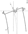
- Figure 2 illustrates a schematic illustration of a cantilever 103 deflected under influence of a static force.
- the deflection under force is discussed as follows. One should first introduce a one-dimensional problem and then later extrapolate to higher dimensions.
- the cantilever 103 is a beam anchored at one end, which may also be referred as a cantilevered fiber.
- Said cantilever or fiber 103 in Fig. 2 has a length L along the x-axis, i.e. horizontal axis. It further has a deflection ⁇ along the y-axis, i.e. vertical axis, caused by a static force F.
- the fiber further has a thickness d and a stiffness EI, where E is the Young's modulus and I is the 2 nd moment of inertia.
- E is the Young's modulus
- I is the 2 nd moment of inertia.
- the 2 nd moment of inertia is also called 2 nd moment of area, moment of inertia of plane area, area moment of inertia, or second area moment.
- Fig. 2 further illustrates the beam deflection in detail.
- the outermost corners, i.e. L lower and L upper , of the fiber 103 are either elongated or shortened by ⁇ L .
- the other parameters, in particular ⁇ and ⁇ ' shown in Fig. 2 were also introduced, above.
- Figure 3A illustrates schematically an arbitrarily deformed element 105, but unlike Fig. 2 now in three dimensions. That is, Fig. 3A illustrates the arbitrarily deformed element 105 having a curvature s and opening angle ⁇ , and radius r.
- the transformation to Cartesian coordinates then is as follows.
- Figure 3B illustrates an element 107.
- Element 107 corresponds to element 105 of Fig. 3A but projected in two dimensions. That is, Fig. 3B illustrates element 107 corresponding to element 105 as shown in Fig. 3A and correspondingly having, in two dimensions, an inner radius r i and an inner curvature s i as well as an outer radius r o and outer curvature s o , and thickness of the substrate d .
- a small element dA of the curved surface A is selected, said small element dA with a rectangular projection onto the original undeformed surface A 0 . It is further assumed that this element may be approximated as being a part of a hollow sphere with the inner radius r i and the outer radius r o .
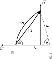
- Figure 4 illustrates a detail of the element of Fig. 3A and 3B .
- the position vector a ⁇ is fully defined by the radius r, the curvature s and opening angle ⁇ , yielding an angle ⁇ .
- FIG. 5 shows a schematic illustration of a unit cell 10 of a strain gauge sensor for the present disclosure.
- This unit cell 10 functions as an element in the matrices discussed above.
- the unit cell 10 corresponds to a strain gauge sensor having conductive lines 3 in a meander-like shape provided on a thin film 1.
- the conductive lines 3 in Fig. 3 are in this Figure and for illustrative purposes oriented horizontally.
- An arrow M indicates the direction of readout, which also is the direction to which all conductive lines of the unit cell are aligned.
- the thin film 1 is a substrate or carrier substrate.
- This substrate may be a thin, i.e. flexible foil of polyethylene terephthalate, PET, foil.
- the PET foil having a stiffness of tensile modulus ⁇ 1000-10000 MPa
- Other materials for the substrate may be any kind of plastic which allow physical vapor deposition.
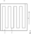
- Figure 6 shows a schematic illustration of a matrix 12 of unit cells of strain gauge sensors, representing one layer, according to the present disclosure.
- Said matrix or layer 12 depicted in Fig. 6 has a quadratic shape with an equal number of rows and columns.
- matrix 12 shows 20 unit cells 10 arranged as a 5x5 matrix. It should be understood that these numbers are for purely illustrative purposes and that other shapes which may be rectangular but not quadratic may be chosen and where the number of rows and columns may be different.
- the all unit cells are arranged to be oriented into the same direction. Thereby, also the readout direction M of all unit cells of the matrix 12 is the same. All unit cells 10 of the matrix 12 may be read out individually, see Fig. 9 .
- Figure 7 shows a schematic illustration of a pair 14 of matrices 12U and 12L.
- the matrices 12U and 12L each may be similar or typically may be the same as the matrix 12 shown in Fig. 7 .
- matrix 12U is the upper matrix of the pair
- matrix 12L is the lower matrix of the pair 14.
- the terms "upper” and “lower” should mean only that in the illustration of Fig. 7 matrix 12U is provided directly above matrix 12L.
- Figure 7 further illustrates that for matrix 12U the readout direction for all of its unit cells 10U is given by direction M U .
- the readout direction for its unit cells 10L is given by readout direction M L .
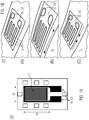
- FIG. 8 shows a schematic illustration of a cross section of a strain gauge measurement blanket 60 according to the present disclosure.
- said blanket 60 comprises a substrate 21, such as a foil or the like is shown in the middle of Fig. 8 .
- a pair P1 of matrices of strain gauge sensors 23 and 25 is shown.
- Said pair P1 of matrices of strain gauge sensors may be the same as the pair of matrices of strain gauge sensors shown in Fig. 7 .
- the readout direction of said matrix 23 is indicated by M2.
- said readout direction M2 is perpendicular to the plane of viewing of this figure.
- said matrix 23 comprises a plurality of unit cells of strain gauge sensors (not shown in Fig. 8 ) which are each aligned with respect to the same direction and said same direction is indicated by M2.
- the readout direction of said matrix 25 is indicated by M1.
- said readout direction M1 is horizontal in the plane of viewing of this figure.
- said matrix 25 also comprises a plurality of unit cells of strain gauge sensors (not shown in Fig. 8 ) which are each aligned with respect to the same direction and said same direction is indicated by M1.
- Fig. 8 another pair P2 is illustrated as being provided directly below the substrate 21.
- Said pair P2 comprises matrices 23 and 25, which are the same as for the pair P1, described above.
- the coordinates of curvature may be sufficiently determined. Providing an even larger number of matrices or layers of strain gauge sensors may provide further redundancy, which may be used minimizing measurement errors.
- Figure 9 illustrates a schematic illustration of a system 50 for curvature measurement according to the present disclosure.
- a plurality of strain gauge sensors e.g. a blanket such as the blanket 60 discussed with respect to Fig. 8 should be read out.
- Each element of each blanket i.e. each sensor 11 of the respective matrices, is read out for its measured data separately by multiplexing.
- a multiplexer 13 is used.
- Said multiplexer 13 is controlled by a clock 19.
- the multiplexer 19 provides the read out data to a resistance meter 15, i.e. an Ohmmeter.
- Said resistance meter 15 may use well-understood resistance measurement method, for example by employing a Wheatstone bridge for this measurement.
- the resistance meter 15 is further connected to a control unit 17 such as a computer. Said control unit 17 is also controlled by the clock 19. Thereby, all elements are connected to their neighbors in measurement direction and are read by applying a voltage to the element with the multiplexer. The elements are measured sequentially in such a way, that the resistance of the prior element can be subtracted from the current measurement. Further, due to the clock, the readout may be performed quasi in real-time.
- the entire blanket 60 of Fig. 8 together with its readout discussed with respect to Fig. 9 may be used in an overlay scheme to determine curvatures of three-dimensionally curved objects.
- the substrate of said blanket 60 may either be substituted or else integrated into specific applications.
- this may be implemented as sensor for flexible displays to compensate the curvature on the fly.
- such a blanket may be integrated into a glove for VR controls, thereby provided a real time positioning sensor.
- a different application may be a waterbed mattress with active pressure compensation or an orthopedic foot measurement sensor for pressure distribution. Further, this may be integrated into a portable PET scanner.
Landscapes
- Physics & Mathematics (AREA)
- General Physics & Mathematics (AREA)
- Force Measurement Appropriate To Specific Purposes (AREA)
Priority Applications (1)
| Application Number | Priority Date | Filing Date | Title |
|---|---|---|---|
| EP18213819.8A EP3671107A1 (de) | 2018-12-19 | 2018-12-19 | Dehnungsmessstreifenkrümmungsmesswerkzeug zur 3d-präzisionspositionskontrolle von dünnen folien |
Applications Claiming Priority (1)
| Application Number | Priority Date | Filing Date | Title |
|---|---|---|---|
| EP18213819.8A EP3671107A1 (de) | 2018-12-19 | 2018-12-19 | Dehnungsmessstreifenkrümmungsmesswerkzeug zur 3d-präzisionspositionskontrolle von dünnen folien |
Publications (1)
| Publication Number | Publication Date |
|---|---|
| EP3671107A1 true EP3671107A1 (de) | 2020-06-24 |
Family
ID=64746034
Family Applications (1)
| Application Number | Title | Priority Date | Filing Date |
|---|---|---|---|
| EP18213819.8A Withdrawn EP3671107A1 (de) | 2018-12-19 | 2018-12-19 | Dehnungsmessstreifenkrümmungsmesswerkzeug zur 3d-präzisionspositionskontrolle von dünnen folien |
Country Status (1)
| Country | Link |
|---|---|
| EP (1) | EP3671107A1 (de) |
Cited By (1)
| Publication number | Priority date | Publication date | Assignee | Title |
|---|---|---|---|---|
| JPWO2022239434A1 (de) * | 2021-05-11 | 2022-11-17 |
Citations (4)
| Publication number | Priority date | Publication date | Assignee | Title |
|---|---|---|---|---|
| US20140015745A1 (en) * | 2012-07-13 | 2014-01-16 | Samsung Electronics Co., Ltd. | Apparatus and method for detecting and handling flexion states of flexible display |
| WO2017094368A1 (ja) * | 2015-12-01 | 2017-06-08 | 日本写真印刷株式会社 | 多点計測用のひずみセンサとその製造方法 |
| US20170176167A1 (en) * | 2015-12-18 | 2017-06-22 | Oculus Vr, Llc | Embroidered strain sensing elements |
| EP3206108A2 (de) * | 2012-08-20 | 2017-08-16 | Samsung Electronics Co., Ltd | Flexible anzeigevorrichtung und steuerungsverfahren dafür |
-
2018
- 2018-12-19 EP EP18213819.8A patent/EP3671107A1/de not_active Withdrawn
Patent Citations (4)
| Publication number | Priority date | Publication date | Assignee | Title |
|---|---|---|---|---|
| US20140015745A1 (en) * | 2012-07-13 | 2014-01-16 | Samsung Electronics Co., Ltd. | Apparatus and method for detecting and handling flexion states of flexible display |
| EP3206108A2 (de) * | 2012-08-20 | 2017-08-16 | Samsung Electronics Co., Ltd | Flexible anzeigevorrichtung und steuerungsverfahren dafür |
| WO2017094368A1 (ja) * | 2015-12-01 | 2017-06-08 | 日本写真印刷株式会社 | 多点計測用のひずみセンサとその製造方法 |
| US20170176167A1 (en) * | 2015-12-18 | 2017-06-22 | Oculus Vr, Llc | Embroidered strain sensing elements |
Cited By (1)
| Publication number | Priority date | Publication date | Assignee | Title |
|---|---|---|---|---|
| JPWO2022239434A1 (de) * | 2021-05-11 | 2022-11-17 |
Similar Documents
| Publication | Publication Date | Title |
|---|---|---|
| CN105899923B (zh) | 具有柔顺层的温度补偿透明力传感器 | |
| US7721610B2 (en) | Rotating body dynamic quantity measuring device and system | |
| US9964672B2 (en) | Method for optimizing a piezoelectric actuator structure for a deformable lens | |
| KR101817966B1 (ko) | 플렉서블 촉각 센서 및 이의 제조 방법 | |
| US20030106378A1 (en) | Determining large deformations and stresses of layered and graded structures to include effects of body forces | |
| US4175445A (en) | Pressure sensing apparatus | |
| US9964755B2 (en) | Optimized actuators for ultra-thin mirrors | |
| US11976988B2 (en) | Force detector and force detection system with layered structure and stress generator | |
| Reinhardt et al. | Ultra-miniature force plate for measuring triaxial forces in the micronewton range | |
| EP3671107A1 (de) | Dehnungsmessstreifenkrümmungsmesswerkzeug zur 3d-präzisionspositionskontrolle von dünnen folien | |
| US3278881A (en) | Membrane strain gauge | |
| CN107452717B (zh) | 半导体制造方法 | |
| JP2025084185A (ja) | 検出装置 | |
| JP5754830B2 (ja) | 精密運動装置 | |
| KR20130038751A (ko) | 센서의 온도 보상 기능을 포함하는 스캐닝 마이크로미러 및 온도 보상 방법 | |
| CN105352445B (zh) | 单边固支板结构变形光纤模式辨识系统及标定方法与应用 | |
| KR20250172938A (ko) | 단방향성, 양방향성 또는 전방향성 변형 측정을 위한 가요성 압전 소자 | |
| CN116124793B (zh) | 一种基于抗弯刚度相对变化层析成像的壁板损伤辨识方法 | |
| CN112595254B (zh) | 一种测量结构双向应变梯度场的方法、传感器及应用 | |
| CN214893116U (zh) | 一种双向应变传感器 | |
| JP5647567B2 (ja) | 応力センサ | |
| US7278327B2 (en) | Film based position and pressure sensor | |
| Tsakiri et al. | Load testing measurements for structural assessment using geodetic and photogrammetric techniques | |
| Peng et al. | Enhancing Wing Shape Reconstruction Precision in FBG Sensors Through Temperature Compensation and Strain Correction Mechanisms | |
| JP2018013339A (ja) | ひずみセンサ、クラック検出用センサ及びクラック検出装置 |
Legal Events
| Date | Code | Title | Description |
|---|---|---|---|
| PUAI | Public reference made under article 153(3) epc to a published international application that has entered the european phase |
Free format text: ORIGINAL CODE: 0009012 |
|
| STAA | Information on the status of an ep patent application or granted ep patent |
Free format text: STATUS: THE APPLICATION HAS BEEN PUBLISHED |
|
| AK | Designated contracting states |
Kind code of ref document: A1 Designated state(s): AL AT BE BG CH CY CZ DE DK EE ES FI FR GB GR HR HU IE IS IT LI LT LU LV MC MK MT NL NO PL PT RO RS SE SI SK SM TR |
|
| AX | Request for extension of the european patent |
Extension state: BA ME |
|
| STAA | Information on the status of an ep patent application or granted ep patent |
Free format text: STATUS: THE APPLICATION IS DEEMED TO BE WITHDRAWN |
|
| 18D | Application deemed to be withdrawn |
Effective date: 20210112 |