EP3671109A2 - Lichtquellenmodul und optisches system für linienabtastbildsystem - Google Patents
Lichtquellenmodul und optisches system für linienabtastbildsystem Download PDFInfo
- Publication number
- EP3671109A2 EP3671109A2 EP19211537.6A EP19211537A EP3671109A2 EP 3671109 A2 EP3671109 A2 EP 3671109A2 EP 19211537 A EP19211537 A EP 19211537A EP 3671109 A2 EP3671109 A2 EP 3671109A2
- Authority
- EP
- European Patent Office
- Prior art keywords
- source
- axis
- section
- light
- line
- Prior art date
- Legal status (The legal status is an assumption and is not a legal conclusion. Google has not performed a legal analysis and makes no representation as to the accuracy of the status listed.)
- Withdrawn
Links
- 230000003287 optical effect Effects 0.000 title claims description 33
- 238000003384 imaging method Methods 0.000 title description 9
- 238000012014 optical coherence tomography Methods 0.000 claims abstract description 28
- 239000004065 semiconductor Substances 0.000 claims abstract description 25
- 239000013307 optical fiber Substances 0.000 claims description 10
- 238000012360 testing method Methods 0.000 claims description 6
- 238000005286 illumination Methods 0.000 description 13
- 239000000835 fiber Substances 0.000 description 11
- 238000013461 design Methods 0.000 description 10
- 230000008878 coupling Effects 0.000 description 7
- 238000010168 coupling process Methods 0.000 description 7
- 238000005859 coupling reaction Methods 0.000 description 7
- 239000012530 fluid Substances 0.000 description 5
- 238000000034 method Methods 0.000 description 5
- 230000003595 spectral effect Effects 0.000 description 5
- 238000013459 approach Methods 0.000 description 4
- 230000000052 comparative effect Effects 0.000 description 4
- 238000001514 detection method Methods 0.000 description 4
- 230000035945 sensitivity Effects 0.000 description 4
- 238000010586 diagram Methods 0.000 description 3
- 239000006185 dispersion Substances 0.000 description 3
- 238000007726 management method Methods 0.000 description 3
- 230000003068 static effect Effects 0.000 description 3
- 230000001131 transforming effect Effects 0.000 description 3
- 238000001943 fluorescence-activated cell sorting Methods 0.000 description 2
- 238000007689 inspection Methods 0.000 description 2
- 239000007788 liquid Substances 0.000 description 2
- 239000004973 liquid crystal related substance Substances 0.000 description 2
- 230000007935 neutral effect Effects 0.000 description 2
- 238000007493 shaping process Methods 0.000 description 2
- 238000001228 spectrum Methods 0.000 description 2
- 230000002269 spontaneous effect Effects 0.000 description 2
- ROGDGDPDLIVQFZ-OGFXRTJISA-N (2r)-2-(4-chloro-2-methylphenoxy)propanoic acid;n-methylmethanamine Chemical compound CNC.OC(=O)[C@@H](C)OC1=CC=C(Cl)C=C1C ROGDGDPDLIVQFZ-OGFXRTJISA-N 0.000 description 1
- 240000004272 Eragrostis cilianensis Species 0.000 description 1
- 206010036618 Premenstrual syndrome Diseases 0.000 description 1
- 230000004075 alteration Effects 0.000 description 1
- 238000003491 array Methods 0.000 description 1
- 230000005540 biological transmission Effects 0.000 description 1
- 230000001413 cellular effect Effects 0.000 description 1
- 238000011109 contamination Methods 0.000 description 1
- 239000007799 cork Substances 0.000 description 1
- 238000012937 correction Methods 0.000 description 1
- 230000003247 decreasing effect Effects 0.000 description 1
- 230000007547 defect Effects 0.000 description 1
- 230000000694 effects Effects 0.000 description 1
- 238000005516 engineering process Methods 0.000 description 1
- 230000005284 excitation Effects 0.000 description 1
- 239000011521 glass Substances 0.000 description 1
- 238000001093 holography Methods 0.000 description 1
- 238000001727 in vivo Methods 0.000 description 1
- 238000011835 investigation Methods 0.000 description 1
- 238000003475 lamination Methods 0.000 description 1
- 239000000463 material Substances 0.000 description 1
- 238000005259 measurement Methods 0.000 description 1
- 238000000386 microscopy Methods 0.000 description 1
- 238000002577 ophthalmoscopy Methods 0.000 description 1
- 230000036961 partial effect Effects 0.000 description 1
- 230000002829 reductive effect Effects 0.000 description 1
- 230000000717 retained effect Effects 0.000 description 1
- 210000001525 retina Anatomy 0.000 description 1
- 230000002207 retinal effect Effects 0.000 description 1
- 239000011343 solid material Substances 0.000 description 1
- 238000012876 topography Methods 0.000 description 1
- 235000012431 wafers Nutrition 0.000 description 1
Images


Classifications
-
- G—PHYSICS
- G02—OPTICS
- G02B—OPTICAL ELEMENTS, SYSTEMS OR APPARATUS
- G02B27/00—Optical systems or apparatus not provided for by any of the groups G02B1/00 - G02B26/00, G02B30/00
- G02B27/09—Beam shaping, e.g. changing the cross-sectional area, not otherwise provided for
- G02B27/0938—Using specific optical elements
- G02B27/095—Refractive optical elements
- G02B27/0955—Lenses
- G02B27/0966—Cylindrical lenses
-
- A—HUMAN NECESSITIES
- A61—MEDICAL OR VETERINARY SCIENCE; HYGIENE
- A61B—DIAGNOSIS; SURGERY; IDENTIFICATION
- A61B5/00—Measuring for diagnostic purposes; Identification of persons
- A61B5/0059—Measuring for diagnostic purposes; Identification of persons using light, e.g. diagnosis by transillumination, diascopy, fluorescence
- A61B5/0062—Arrangements for scanning
- A61B5/0066—Optical coherence imaging
-
- G—PHYSICS
- G01—MEASURING; TESTING
- G01B—MEASURING LENGTH, THICKNESS OR SIMILAR LINEAR DIMENSIONS; MEASURING ANGLES; MEASURING AREAS; MEASURING IRREGULARITIES OF SURFACES OR CONTOURS
- G01B9/00—Measuring instruments characterised by the use of optical techniques
- G01B9/02—Interferometers
- G01B9/02034—Interferometers characterised by particularly shaped beams or wavefronts
- G01B9/02035—Shaping the focal point, e.g. elongated focus
- G01B9/02037—Shaping the focal point, e.g. elongated focus by generating a transverse line focus
-
- G—PHYSICS
- G01—MEASURING; TESTING
- G01B—MEASURING LENGTH, THICKNESS OR SIMILAR LINEAR DIMENSIONS; MEASURING ANGLES; MEASURING AREAS; MEASURING IRREGULARITIES OF SURFACES OR CONTOURS
- G01B9/00—Measuring instruments characterised by the use of optical techniques
- G01B9/02—Interferometers
- G01B9/0209—Low-coherence interferometers
- G01B9/02091—Tomographic interferometers, e.g. based on optical coherence
-
- G—PHYSICS
- G01—MEASURING; TESTING
- G01N—INVESTIGATING OR ANALYSING MATERIALS BY DETERMINING THEIR CHEMICAL OR PHYSICAL PROPERTIES
- G01N15/00—Investigating characteristics of particles; Investigating permeability, pore-volume or surface-area of porous materials
- G01N15/10—Investigating individual particles
- G01N15/14—Optical investigation techniques, e.g. flow cytometry
- G01N15/1434—Optical arrangements
- G01N15/1436—Optical arrangements the optical arrangement forming an integrated apparatus with the sample container, e.g. a flow cell
-
- G—PHYSICS
- G02—OPTICS
- G02B—OPTICAL ELEMENTS, SYSTEMS OR APPARATUS
- G02B19/00—Condensers, e.g. light collectors or similar non-imaging optics
- G02B19/0004—Condensers, e.g. light collectors or similar non-imaging optics characterised by the optical means employed
- G02B19/0009—Condensers, e.g. light collectors or similar non-imaging optics characterised by the optical means employed having refractive surfaces only
- G02B19/0014—Condensers, e.g. light collectors or similar non-imaging optics characterised by the optical means employed having refractive surfaces only at least one surface having optical power
-
- G—PHYSICS
- G02—OPTICS
- G02B—OPTICAL ELEMENTS, SYSTEMS OR APPARATUS
- G02B19/00—Condensers, e.g. light collectors or similar non-imaging optics
- G02B19/0033—Condensers, e.g. light collectors or similar non-imaging optics characterised by the use
- G02B19/0047—Condensers, e.g. light collectors or similar non-imaging optics characterised by the use for use with a light source
- G02B19/0052—Condensers, e.g. light collectors or similar non-imaging optics characterised by the use for use with a light source the light source comprising a laser diode
-
- G—PHYSICS
- G02—OPTICS
- G02B—OPTICAL ELEMENTS, SYSTEMS OR APPARATUS
- G02B27/00—Optical systems or apparatus not provided for by any of the groups G02B1/00 - G02B26/00, G02B30/00
- G02B27/09—Beam shaping, e.g. changing the cross-sectional area, not otherwise provided for
- G02B27/0911—Anamorphotic systems
-
- G—PHYSICS
- G02—OPTICS
- G02B—OPTICAL ELEMENTS, SYSTEMS OR APPARATUS
- G02B27/00—Optical systems or apparatus not provided for by any of the groups G02B1/00 - G02B26/00, G02B30/00
- G02B27/09—Beam shaping, e.g. changing the cross-sectional area, not otherwise provided for
- G02B27/0916—Adapting the beam shape of a semiconductor light source such as a laser diode or an LED, e.g. for efficiently coupling into optical fibers
-
- G—PHYSICS
- G02—OPTICS
- G02B—OPTICAL ELEMENTS, SYSTEMS OR APPARATUS
- G02B27/00—Optical systems or apparatus not provided for by any of the groups G02B1/00 - G02B26/00, G02B30/00
- G02B27/09—Beam shaping, e.g. changing the cross-sectional area, not otherwise provided for
- G02B27/0938—Using specific optical elements
- G02B27/0977—Reflective elements
-
- G—PHYSICS
- G02—OPTICS
- G02B—OPTICAL ELEMENTS, SYSTEMS OR APPARATUS
- G02B27/00—Optical systems or apparatus not provided for by any of the groups G02B1/00 - G02B26/00, G02B30/00
- G02B27/30—Collimators
-
- G—PHYSICS
- G02—OPTICS
- G02B—OPTICAL ELEMENTS, SYSTEMS OR APPARATUS
- G02B6/00—Light guides; Structural details of arrangements comprising light guides and other optical elements, e.g. couplings
- G02B6/0001—Light guides; Structural details of arrangements comprising light guides and other optical elements, e.g. couplings specially adapted for lighting devices or systems
- G02B6/0011—Light guides; Structural details of arrangements comprising light guides and other optical elements, e.g. couplings specially adapted for lighting devices or systems the light guides being planar or of plate-like form
- G02B6/0013—Means for improving the coupling-in of light from the light source into the light guide
- G02B6/0023—Means for improving the coupling-in of light from the light source into the light guide provided by one optical element, or plurality thereof, placed between the light guide and the light source, or around the light source
- G02B6/003—Lens or lenticular sheet or layer
-
- A—HUMAN NECESSITIES
- A61—MEDICAL OR VETERINARY SCIENCE; HYGIENE
- A61B—DIAGNOSIS; SURGERY; IDENTIFICATION
- A61B3/00—Apparatus for testing the eyes; Instruments for examining the eyes
- A61B3/10—Objective types, i.e. instruments for examining the eyes independent of the patients' perceptions or reactions
- A61B3/102—Objective types, i.e. instruments for examining the eyes independent of the patients' perceptions or reactions for optical coherence tomography [OCT]
-
- H—ELECTRICITY
- H01—ELECTRIC ELEMENTS
- H01S—DEVICES USING THE PROCESS OF LIGHT AMPLIFICATION BY STIMULATED EMISSION OF RADIATION [LASER] TO AMPLIFY OR GENERATE LIGHT; DEVICES USING STIMULATED EMISSION OF ELECTROMAGNETIC RADIATION IN WAVE RANGES OTHER THAN OPTICAL
- H01S3/00—Lasers, i.e. devices using stimulated emission of electromagnetic radiation in the infrared, visible or ultraviolet wave range
- H01S3/005—Optical devices external to the laser cavity, specially adapted for lasers, e.g. for homogenisation of the beam or for manipulating laser pulses, e.g. pulse shaping
Definitions
- the invention relates to line-field illumination systems that use light from semiconductor light sources, such as light emitting diodes, semiconductor lasers, swept source semiconductor lasers and superluminescent diodes.
- semiconductor light sources such as light emitting diodes, semiconductor lasers, swept source semiconductor lasers and superluminescent diodes.
- Bonin et al claim a minimal parallel acquisition speed of 100 Hz is needed to avoid substantial loss in sensitivity and structural compliance. This can however only be achieved in full-field OCT by using expensive high-speed sensor technology. In addition, full-field OCT lacks the confocal gating, that helps to suppress out-of-focus light that otherwise reduces the dynamic range of the sensor and ultimately the detection sensitivity.
- a potential alternative is line-field OCT, which retains partial confocal gating, as well as the sensitivity advantage of parallel acquisition (see Fechtig et al [3]). Those advantages hold also for any other line-field scanning imaging systems, such as line scanning laser microscopy or ophthalmoscopy. In general, line-field illumination allows for higher illuminance, when laser safety considerations set limits on the sample exposure.
- the coupling of light emitted from an edge-emitting semiconductor light source into an illumination system is most commonly implemented by transforming the divergent elliptical cross-section beam emitted from the source into a circular cross-section beam and collimating it using collimation optics. This can be achieved by arranging two cylindrical lenses of different focal lengths orthogonal to each other separated from the output face of the (point) source by their respective focal lengths.
- Another approach to convert the divergent, elliptical cross-section beam into a circular, collimated one is to couple the source output beam into a single-mode fiber, the output of which is a circular, Gaussian beam.
- a spherical lens can then be arranged downstream of the fiber's output end to produce a collimated, circular beam.
- Fiber coupling is however accompanied by significant optical power losses. To compensate for any power losses, the source needs to output a higher power and thus be driven with a higher drive current. An increase in drive current is, however, associated with a decreased lifetime for
- the light distribution after emission from an edge-emitting laser chip intrinsically has a non-circular, extended cross-section in far field that may be approximated as an ellipse. This property is exploited by certain embodiments of the invention to provide a line focus with more desirable properties compared with the standard approach of focusing a circular, Gaussian beam with a cylindrical lens.
- a semiconductor source module comprising a source operable to emit a divergent, output beam of circular or elliptical cross-section.
- Collimation optics are arranged to convert the source output beam into a non-divergent, collimated beam of elliptical cross-section having a major axis and a minor axis.
- a line-focusing cylindrical lens having a piano axis and a power axis is also provided and is arranged with its piano axis aligned with the major axis of the collimated beam and its power axis aligned with the minor axis of the collimated beam so as to form a line focus extending along the major axis of the collimated beam.
- the collimation optics comprises a first collimating cylindrical lens which collimates the beam in a first plane and a second collimating cylindrical lens which collimates the beam in a second plane orthogonal to the first plane, the first and second collimating cylindrical lenses being spaced apart by a distance which defines the ratio between the respective diameters of the major and minor axes of the collimated beam, i.e. the aspect ratio. Designs of this kind allow a flexible collimation of divergent output beams of circular or elliptical shape into a collimated, elliptical beam with any desired aspect ratio.
- the collimation optics comprises a spherical lens or an aspherical lens.
- example sources are edge-emitting semiconductor sources, such as semiconductor lasers (sweepable or fixed wavelength), superluminescent diodes and light-emitting diodes.
- example sources include a vertical cavity surface emitting laser and an optical fiber (e.g. optical fiber laser, amplified spontaneous emission source, or optical fiber waveguide provided to deliver output from a separate source whose output is coupled into a distal end of the optical fiber).
- Embodiments of the invention are capable of providing improved line-field illumination schemes by exploiting the intrinsic anamorphic beam properties of edge-emitting semiconductor sources such as light emitting diodes including organic light emitting diodes, superluminescent diodes, lasers and so forth.
- edge-emitting semiconductor sources such as light emitting diodes including organic light emitting diodes, superluminescent diodes, lasers and so forth.
- an elliptical profile causes loss of light when coupled into a single mode fiber, from its geometry it is intrinsically better suited to line illumination schemes.
- the intrinsically elliptical profile output from an edge-emitting semiconductor source is used without first converting it via conventional collimating optics into a circular, collimated beam and in particular without first passing the output light through a single-mode fiber.
- the full output power of the source is retained.
- an optical coherence tomography system comprising: a semiconductor source module according to the first aspect of the invention, a beam splitter arranged to receive light output from the source module and to direct one component into a first, sample arm to an optical test sample and another component to a second, reference arm, and to recombine light received back from the first and second arms and direct the recombined light to a detector.
- the line focus of the divergent elliptical beam output from the source is performed with a combination of two cylindrical lenses for collimating the beam into a cross-sectional height and width matched to a third cylindrical lens which is used to focus the collimated beam into a line.
- This embodiment can also be used to generate a line focus from a divergent circular beam, such as output by an optical fiber or vertical cavity surface emitting laser.
- the output from the optical fiber may be generated in the fiber itself, e.g. the fiber may comprise an optical fiber laser or an amplified spontaneous emission (ASE) source, or the fiber may be a delivery conduit for the output from an external source, such as a laser or diode, the output of which is coupled into a distal end of the fiber.
- ASE amplified spontaneous emission
- FIG. 1 For example system applications of the source module are as follows: In a flow cytometer system in which a flow cell comprising a sample capillary tube is arranged so that the line focus intersects with sample in the capillary tube.
- a display device comprising a display panel; and an edge-lit backlight unit with a light guide layer arranged under the display panel, the source module being arranged with its line focus aligned along an edge of the light guide layer, thereby to provide the backlighting.
- a mirror deflection device comprising: a planar mirror, in which the source module is arranged to illuminate the planar mirror with a light beam of elliptical cross-section, said light beam being deflected by the mirror so as to change the aspect ratio of its cross-section, the source module being configured to output a beam of a cross-section specified to provide a desired cross-section in the light beam deflected from the mirror.
- Figure 1 is a schematic drawing of a generic semiconductor source 1 and the divergent elliptical beam shape 2 of its output.
- the semiconductor chip of the source is made of epitaxial layers extending in the yz-planes as schematically depicted.
- the illustrated output face of the chip is in the xy-plane.
- the source's output beam 2 is of elliptical shape in the far field, with the major (i.e. long) axis of the ellipse being in the x-direction, the minor (i.e. short) axis in the y-direction, and the optical axis O of the output beam in the z-direction.
- the output beam characteristics of a semiconductor source are due to diffraction at the output face of the chip and the degree of ellipticity, divergence and other parameters of the output beam can be controlled somewhat through the cavity design.
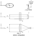
- Figure 2 shows a source module according to one embodiment with reference to an optical axis O in the z-direction.
- the divergent output beam 2 from the source 1 is collimated by collimation optics 3 into a collimated beam 4.
- the collimation optics 3 can for example be a spherical lens, aspherical lens or equivalent lens combination.
- the system may optionally include one or more further optical components 3' to homogenize illuminance across the beam cross-section.
- a beam-shaping device may be provided for producing a close-to-rectangular shaped beam profile, a Powell lens, diffractive optics or phase plates.
- the collimated beam 4 can then be used for any desired line-field imaging modality, for line-field projection devices, or for coupling into one or more waveguides, such as waveguide arrays or optical fiber bundles.
- the downstream optical components are generically shown as optical sub-system 5.
- the optical sub-system 5 includes at its input a single cylindrical lens 6, or functionally equivalent lens or mirror combination, that focuses the elliptical collimated beam 4 to a line 7 in the focal plane f with the line focus extending in the x-direction (out of the plane of Figure 2 ) and having a narrow width in the y-direction.
- Figure 3 is a schematic perspective view of the cylindrical lens 6 of Figure 2 , where x is the piano axis, y is the power axis, and z (or O) is the optical axis.
- Figure 4 is a view along the optical axis O of the line focus of the cylindrical lens of Figure 2 , with the focal plane of the cylindrical lens 6, which is a plane in xy, being the plane of the paper.
- the line focus has a focal extension in the x-direction and a focal width in the y-direction.
- the focal extension and width can each be measured in terms of the FWHM, 1/e 2 or some other parameter that is suitable for measuring a falling profile, such as a Gaussian, compared with the peak, i.e. maximum, intensity at the optical axis.
- the dashed line in Figure 4 represents the FWHM value for the intensity.
- Figures 5A & 5B are respectively plan and side views of a source module according to another embodiment.
- the divergent output light 2 from the source 1 is collimated by collimation optics 3 comprising a first cylindrical lens 3a arranged a distance d1 from the source which collimates the beam in the yz-plane as shown in Figure 3A , and a second cylindrical lens 3b arranged a distance d2 from the source (where d2>d1) which collimates the beam in the xz-plane as shown in Figure 3B after letting the beam propagate further and hence diverge more.
- collimation optics 3 comprising a first cylindrical lens 3a arranged a distance d1 from the source which collimates the beam in the yz-plane as shown in Figure 3A , and a second cylindrical lens 3b arranged a distance d2 from the source (where d2>d1) which collimates the beam in the xz-plane as shown in Figure 3B after letting the beam propagate
- the first cylindrical lens 3a has its power axis in the y-direction and its piano axis in the x-direction
- the second cylindrical lens 3b has its power axis in the x-direction and its piano axis in the y-direction.
- FIG. 5A & 5B An important additional point in relation to the arrangement of Figures 5A & 5B is that such an arrangement is not only suitable for transforming an elliptical cross-section, divergent beam from a source, such as an edge-emitting semiconductor source, into an elliptical cross-section, collimated beam, but is also suitable for transforming a circular cross-section, divergent beam from a source, such as an optical fiber or a vertical cavity surface emitting laser (VCSEL), into an elliptical cross-section, collimated beam.
- VCSEL vertical cavity surface emitting laser
- first and second cylindrical lenses 3a and 3b are arbitrary, the relevant factor being that their piano axes are orthogonal to each other.
- Further optical components 3' may be provided to homogenize illuminance across the beam cross-section as described above in relation to Figure 2 .
- An optical system 5 arranged downstream to receive the collimated output of the collimation optics 3 may for example include at its input a single cylindrical lens 6, or functionally equivalent lens or mirror combination, that focuses the elliptical collimated beam 4 to a line 7 in the focal plane f with the focus extension being in the x-direction and the focus width being in the y-direction.
- Figure 6 shows various schematic views of the background example with a circular collimated beam incident on the cylindrical lens.
- Figure 7 shows various schematic views of the comparative example, labelled "short-x", with an elliptical collimated beam incident on the cylindrical lens with the ellipse having its minor axis in the x-direction and its major axis in the y-direction.
- Figure 8 shows various schematic views of an example according to an embodiment of the invention, labelled "long-x", with an elliptical collimated beam incident on the cylindrical lens with the ellipse having its minor axis in the y-direction and its major axis in the x-direction.
- FIG. 6 , 7 and 8 have the same lay out with representations in the xy-plane (top), yz-plane (middle) and xz-plane (bottom).
- the middle and bottom representations show plan and side views respectively of the collimated beam being focused in the focal plane f by the cylindrical lens 6.
- the top-left representation shows the collimated beam cross-section.
- the top-right representation shows the line focus in the focal plane f .
- the light sources used were superluminescent diodes (SLDs), specifically Superlum (trade mark of Superlum Diodes Limited, Cork, Ireland) broadband light sources with model numbers SLD-CS-371-HP3-SM-840-I for the circular beam and SLD-340-UHP-TO9-PD with a Thorlabs SLD driver for the elliptical beam (Thorlabs is a trademark of Thorlabs, Inc).
- SLDs superluminescent diodes
- Superlum trade mark of Superlum Diodes Limited, Cork, Ireland
- Thorlabs is a trademark of Thorlabs, Inc.
- These SLDs have a strong divergence of >15° which is collimated using a C110TMD-B lens from Thorlabs.
- the output beam of the SLD is an elliptical collimated beam with a long axis extension of 3770 ⁇ m and a short axis extension of 2030 ⁇ m. The collimation was controlled visually over a distance of 4 m
- Figure 6 (circular; background): A circular cross-section, Gaussian beam is input into a cylindrical lens 6 aligned with its piano axis in the x-direction and its power axis in the y-direction to generate a line focus extending in the x-direction.
- Figure 7 (short-x; comparative): The piano axis of the cylindrical lens 6 is aligned with the short axis of the collimated elliptical beam in the x-direction and the power axis of the cylindrical lens is aligned with the long axis of the collimated elliptical beam in the y-direction to generate a line focus with a relatively short extension along the x-direction, the extension having a length approximately equal to the minor axis dimension of the ellipse.
- Figure 8 (long-x; embodiment): The piano axis of the cylindrical lens 6 is aligned with the long axis of the collimated elliptical beam in the x-direction and the power axis of the cylindrical lens is aligned with the short axis of the collimated elliptical beam in the y-direction to generate a line focus with a relatively long extension along the x-direction, the extension having a length approximately equal to the major axis dimension of the ellipse.
- Figure 9 is a graphical representation of test results from the examples of Figures 6 , 7 and 8 plotting the extension of the line focus against the width of the line focus.
- FWHM full width half maximum
- the focus becomes increasingly more diffuse, i.e. less tight, the further one moves away from the optical axis in the x-direction.
- As a measure of the extension of the line focus along its length we measured the x-values either side of the optical axis at which the FWHM was 25% higher than the FWHM at the optical axis, i.e. the minimum FWHM.
- both the absolute values of the FWHM of the focus and their decrease along the x-direction is similar for the "circular” and “short-x” examples.
- the circular beam has a minimum FWHM of 20.7 ⁇ m.
- the minimum FWHM is 18 ⁇ m. From theory, we would have expected the "short-x” example to have a FWHM lower than that of the "circular” example by a factor of 1.8. The fact that our experimental results do not show this may be explained by imperfect collimation of the elliptical beam and/or by the presence of multiple modes in the source output.
- the proposed approach can therefore make more efficient use of the output power of a semiconductor source, so the source can be run at reduced output power, resulting in a longer source lifetime by taking advantage of the intrinsic ellipticity of a source's divergent output beam for devices that require a line focus to be inputted.
- the above-described lens components e.g. elements 3 (or 3a & 3b), 4 & 6, and the beam shaping optics 3', can be either refractive or diffractive elements, or combinations of both.
- FWHM the measure of the drop off in power away from the optical axis (z-axis) along the extension of the line focus (x-direction) and across the focus (y-direction).
- any other measure of power drop-off could be used, such as the inverse e-squared value (1/e 2 ).
- FIG 10 is a schematic drawing of two variants of a line-field Fourier domain OCT system employing the proposed management of the elliptical beam in a source module according to the invention as described in relation to Figures 1 to 9 .
- the illustrated axes yz (with axis x perpendicular to the paper) correspond to those in Figure 1 to 9 and apply to the light beam emitted from the source SLD/SS, so that these axes need to be correspondingly transformed by 90 degrees after mirror M1.
- collimating lens L0 corresponds to lenses 3 or 3a/3b
- cylindrical lens CL1 corresponds to lens 6.
- Configuration (a) is a spectral domain system using a broad band source and a detector comprising a grating to separate the wavelengths spatially so that the separated spectra are projected onto a two-dimensional (2d), i.e. array, sensor.
- Configuration (b) is a swept source configuration, in which, for the detector, instead of using a grating only an achromatic lens is used, which focuses the light onto a one-dimensional (1d), i.e. line, sensor, in which case the spectra from the different wavelengths are acquired in a time series as the source is swept.
- a beam splitter BS is arranged to split the light into a first component and a second component.
- the first component traverses a sample arm by being projected onto a single-axis galvanometer scanner GS for a dynamic line-field OCT system (or onto a mirror M4 - not shown, but arranged in the same place as scanner GS, for a static line-field OCT system).
- the light is reflected by approximately 90° from the galvo scanner GS (or exactly 90° from the mirror M4).
- the focal distance of CL1 is chosen to be on the galvanometer scanner GS (or mirror M4).
- the beam is collimated by lens L1, projected onto mirror M3 and once again focused using lens L2.
- a human eye is placed with its lens being at the focal position of lens L2 as illustrated.
- the light which is backscattered from the retina is directed back through the same path until beam splitter BS.
- the backscattered component interferes with the second component returning from the reference arm.
- the source light after passing for the first time through the beam splitter BS passes through a neutral density filter NDF to adjust the power; after that it is recollimated by cylindrical lens CL2 and reflected by 90° using mirror M2.
- the detector comprises a diffraction grating GR which spatially separates the wavelength components and projects them onto a 2d sensor via a collimating lens L5, this 2d setup being suitable in a spectral domain configuration using a broadband source such as the superluminescent diode SLD.
- the illustrated transmission diffraction grating GR could be replaced by a reflection diffraction grating.
- the light from lens L4 is passed to a collimating lens L5 which projects the light onto a 1d line sensor, this 1d sensor setup being suitable if using a spectral domain arrangement or a (wavelength) swept source such as a swept source laser or a semiconductor optical amplifier (SOA). More details describing this setup can be found in [3,4], the full contents of which is incorporated herein by reference.
- OCT optical coherence tomography
- PCBs printed circuit boards
- spectral domain OCT system is described for example in CN103115580A [5].
- This prior art document uses a 2D scanning galvanometer mirror to scan over the PCB. In our system implementation, a 1D scanning galvanometer mirror would be used, which would be quicker.
- the source module includes the following components of Figure 10 : SLD/SS, L0, S1, M1 and CL1. If desired the source module may additionally accommodate further downstream components of the OCT system such as the beam splitter BS, or the beam splitter BS and GS/M4.
- FIG 11 is a schematic diagram of an example flow cytometer design using line-field illumination that incorporates a source module according to Figures 2 to 4 , or Figures 5A & 5B , or Figure 8 for coupling the source light into the flow cell region of the flow cytometer.
- Flow cytometers are widely used for analyzing properties of cells that are suspended in a liquid. The liquid is passed through a conduit so that the cells flow past a fluorescence-based sensing device one at a time. The cells can thus be counted and classified according to their spectroscopic properties which can then optionally be used to further direct the flow or for other purposes. For example, the cells can be sorted downstream of the detection device according to their fluorescence properties.
- the flow cytometer has a flow cell 10 which receives a sample inlet tube 12.
- the sample inlet tube 12 is connected to an inner capillary tube 14 of the flow cell 10 which is radially enclosed prior to its termination by a sheath 16 which has a sheath inlet 18 connected to a sheath fluid inlet tube (not shown).
- the sheath 16 reduces in its cross-sectional diameter and the inner capillary tube 14 terminates leaving the sample fluid and sheath fluid flowing together along a capillary tube 20.
- the sample flows radially confined to the central region of the flow by virtue of laminar flow at the interface between the sample fluid and the sheath fluid.
- the aim of this sheath arrangement is to allow good optical access to the sample in a flow tube that is sufficiently large in diameter to avoid blockages.
- the various optical components for excitation and collection are arranged about a measurement region of the capillary tube 20.
- the flow cytometer has a source module according to Figures 2 to 4 , or Figures 5A & 5B , or Figure 8 comprising a source 1 emitting a divergent output beam that is collimated by collimation optics 3 into a collimated beam and an optical sub-system 5 that focuses the elliptical collimated beam 4 to a line 7 in the focal plane f with the line focus extending in the flow direction, which is the x-direction, to intersect with sample in the capillary tube 20, e.g. coincident with the central axis of the cylindrical capillary tube 20.
- the line focus is in the x-direction and has a narrow width in the y-direction (out of the paper in Figure 11 ).
- Fluorescence from the sample excited by the source 22 is then collected through a collection lens 28 and spectral sorting arrangement 30, comprising mirrors 32 and filters 34, which divides the fluorescence into different wavelength bands.
- a collection lens 28 and spectral sorting arrangement 30 comprising mirrors 32 and filters 34, which divides the fluorescence into different wavelength bands.
- Each color component is directed to a suitable photomultiplier tube (PMT) 361, 362, 363, 364 as illustrated with the example of four PMTs.
- a forward scatter (FSC) detector 35 and side scatter (SSC) detector 37 may also be provided and are schematically depicted.
- Line-field imaging modalities are, in the context of the invention, understood as including methods that illuminate the sample with a line.
- Line-field imaging modalities may use parallel detection along an array of sensor elements that records the line-field light backscattered or reflected from or transmitted through an object.
- the line may also be scanned across the sample, or the sample be moved relative to the illumination.
- the imaging technique may further employ interferometric signal modulation by using a reference arm such as in line-field OCT or line-field holography.
- Example applications of the proposed management of the elliptical beam according to the invention as described in relation to Figures 1 to 9 further include: line-field imaging and sensing techniques, where the beam is kept static; line-field imaging and sensing techniques, where the beam is scanned across an object; line-field illumination, where the beam is kept static; and line-field illumination, where the beam is scanned.
- Line-field projection devices are, in the context of the invention, understood as including methods that steer a line-shaped beam across an object.
- FIG 12 is a schematic plan view of an OCT system embodying the invention being used to measure properties of display panels, such as thickness uniformity and integrity and contamination of laminations or other bonding material, e.g. with foreign bodies, used to fuse panel layers together.
- OCT for such an application is known from Cho et al [6].
- a conveyer belt 40 conveys display panels 42 past a line focus 7 as output from the apparatus of Figure 2 or Figure 5A/5B .
- OCT is performed to measure the thickness of the panels, e.g. by measuring the vertical distance between upper and lower surfaces of a single piece of solid material, e.g. glass, or the vertical distance between surfaces that span an air gap as might be relevant for liquid crystal displays where the space formed by the gap is to be filled with liquid crystal.
- the line focus provides for more rapid scanning than a spot focus which would need to be scanned over the panel surface as in Cho et al ibid.
- Another specific example where a line focus is convenient is for inspection by OCT or other optical technique of a product for defects such as cracks or weld faults. If the product is elongate, like a railway rail, then the line focus can be arranged transverse to the rail as the line focus is moved along the rail.
- Figure 13 shows in third-angle projection a prior art edge-lit backlight unit for a display 50 based on a strip of light emitting diodes (LEDs) 52.
- the LEDs emit into a light guide layer 54 which provides backlighting to the display panel 58, e.g. LCD or OLED, through a diffuser 56.
- the LEDs may be white, or a sequence of RGB emitters.
- Figure 14 shows an edge-lit backlight unit for a display according to an embodiment.
- the LED strip is replaced with a line focus 7 as output from the source module of Figure 2 or Figure 5A/5B .
- the light guide layer 54 is arranged under the display panel 58.
- the source module is arranged with its line focus 7 aligned along an edge of the light guide layer 54. In this way, a much lower number of SLEDs may be used to replace a much larger number of LEDs.
- Figure 15 is a schematic side view of a beam deflecting planar mirror 60 arranged at an arbitrary angle to an incoming beam according to a further embodiment.
- the effect of the mirror 60 is to transform the aspect ratio of the incoming beam in relation to the outgoing beam (unless the angle of incidence is 45 degrees).
- the arrangement of Figures 5A/5B can be used to tune the aspect ratio of the incoming beam to the value required to cause the outgoing beam to have a specified aspect ratio in cross-section. This can even be done dynamically by controlling the distance between lenses 3a and 3b, e.g. with a motor-driven linear translator, so that tilting of the mirror 60 at different angles can be compensated for during operation.
- the beam might also be spatially modulated, e.g. by using digital mirror devices, spatial light modulators or similar.
Landscapes
- Physics & Mathematics (AREA)
- General Physics & Mathematics (AREA)
- Optics & Photonics (AREA)
- Health & Medical Sciences (AREA)
- General Health & Medical Sciences (AREA)
- Nuclear Medicine, Radiotherapy & Molecular Imaging (AREA)
- Life Sciences & Earth Sciences (AREA)
- Radiology & Medical Imaging (AREA)
- Chemical & Material Sciences (AREA)
- Pathology (AREA)
- Analytical Chemistry (AREA)
- Biochemistry (AREA)
- Dispersion Chemistry (AREA)
- Immunology (AREA)
- Biophysics (AREA)
- Engineering & Computer Science (AREA)
- Biomedical Technology (AREA)
- Heart & Thoracic Surgery (AREA)
- Medical Informatics (AREA)
- Molecular Biology (AREA)
- Surgery (AREA)
- Animal Behavior & Ethology (AREA)
- Public Health (AREA)
- Veterinary Medicine (AREA)
- Investigating Or Analysing Materials By Optical Means (AREA)
Applications Claiming Priority (1)
| Application Number | Priority Date | Filing Date | Title |
|---|---|---|---|
| GB1820792.8A GB2580052B (en) | 2018-12-20 | 2018-12-20 | Source module and optical system for line-field imaging |
Publications (2)
| Publication Number | Publication Date |
|---|---|
| EP3671109A2 true EP3671109A2 (de) | 2020-06-24 |
| EP3671109A3 EP3671109A3 (de) | 2020-09-16 |
Family
ID=65364364
Family Applications (1)
| Application Number | Title | Priority Date | Filing Date |
|---|---|---|---|
| EP19211537.6A Withdrawn EP3671109A3 (de) | 2018-12-20 | 2019-11-26 | Lichtquellenmodul und optisches system für linienabtastbildsystem |
Country Status (3)
| Country | Link |
|---|---|
| US (1) | US11086133B2 (de) |
| EP (1) | EP3671109A3 (de) |
| GB (1) | GB2580052B (de) |
Cited By (1)
| Publication number | Priority date | Publication date | Assignee | Title |
|---|---|---|---|---|
| CN114967127A (zh) * | 2022-06-16 | 2022-08-30 | 曹桂源 | 多波长消色差超薄平面透镜的设计方法 |
Families Citing this family (9)
| Publication number | Priority date | Publication date | Assignee | Title |
|---|---|---|---|---|
| JP2021024225A (ja) * | 2019-08-07 | 2021-02-22 | 株式会社リコー | 照射光学系および光照射装置および3次元造形装置 |
| US11920930B2 (en) * | 2020-01-31 | 2024-03-05 | Cornell University | Light-sheet photonic-force optical coherence elastography |
| US20240250495A1 (en) * | 2020-08-27 | 2024-07-25 | Richard Redpath | Method And Apparatus For A Fast Axis Laser Line |
| US11262184B1 (en) | 2020-10-28 | 2022-03-01 | Mitsubishi Electric Research Laboratories, Inc. | Optical coherence tomography (OCT) system for producing profilometry measurements of a specimen |
| US11578965B2 (en) | 2021-05-26 | 2023-02-14 | Hong Kong Applied Science and Technology Research Institute Company Limited | Cost-effective line-scan optical coherence tomography apparatus |
| CN113518909A (zh) * | 2021-05-26 | 2021-10-19 | 香港应用科技研究院有限公司 | 具有成本效益的直线扫描光学相干断层成像装置 |
| JPWO2023182371A1 (de) * | 2022-03-25 | 2023-09-28 | ||
| JP2024132091A (ja) * | 2023-03-17 | 2024-09-30 | セイコーエプソン株式会社 | 生体情報測定装置、及び生体情報測定システム |
| KR102691411B1 (ko) * | 2023-11-20 | 2024-08-05 | 주식회사 오토피디아 | 레이저 빔 조사 장치 및 방법 |
Citations (1)
| Publication number | Priority date | Publication date | Assignee | Title |
|---|---|---|---|---|
| CN103115580A (zh) | 2013-01-23 | 2013-05-22 | 刘茂珍 | 基于光学相干层析扫描的三维孔形检测方法及系统 |
Family Cites Families (20)
| Publication number | Priority date | Publication date | Assignee | Title |
|---|---|---|---|---|
| US5155631A (en) * | 1990-10-01 | 1992-10-13 | The United States Of America As Represented By The Department Of Energy | Method for fabrication of cylindrical microlenses of selected shape |
| US5181224A (en) * | 1991-05-10 | 1993-01-19 | University Of California | Microoptic lenses |
| WO2004085108A1 (ja) * | 1993-08-05 | 2004-10-07 | Nobuhiko Tada | リードフレーム加工方法及びリードフレーム加工装置 |
| JP2951842B2 (ja) * | 1993-08-13 | 1999-09-20 | 東芝テック株式会社 | 光走査装置 |
| KR100335624B1 (ko) * | 1995-01-24 | 2002-11-22 | 삼성전기주식회사 | 레이저빔주사장치 |
| US6396616B1 (en) * | 2000-10-10 | 2002-05-28 | 3M Innovative Properties Company | Direct laser imaging system |
| US6570659B2 (en) * | 2001-03-16 | 2003-05-27 | Lightlab Imaging, Llc | Broadband light source system and method and light source combiner |
| KR100644967B1 (ko) * | 2004-10-27 | 2006-11-15 | 한국과학기술연구원 | 다양한 크기의 양자점으로 이루어진 활성층을 이용하는고휘도 발광소자 및 그 제조 방법 |
| JP4727517B2 (ja) | 2006-01-11 | 2011-07-20 | 富士フイルム株式会社 | 光源装置および光断層画像化装置 |
| DE102006015387A1 (de) * | 2006-04-03 | 2007-10-04 | Robert Bosch Gmbh | Interferometrische Messvorrichtung |
| US7400457B1 (en) * | 2007-01-04 | 2008-07-15 | Stockeryale Canada Inc. | Rectangular flat-top beam shaper |
| JP5154838B2 (ja) * | 2007-05-31 | 2013-02-27 | 株式会社ディスコ | レーザー加工装置 |
| KR100884353B1 (ko) * | 2007-09-18 | 2009-02-18 | 한국전자통신연구원 | 고휘도 다이오드 및 그 제조 방법 |
| US8948846B2 (en) * | 2007-09-19 | 2015-02-03 | The Research Foundation Of State University Of New York | Optical coherence tomography systems and methods |
| US8215776B2 (en) * | 2009-01-07 | 2012-07-10 | Eastman Kodak Company | Line illumination apparatus using laser arrays |
| EP2697692B1 (de) * | 2011-06-10 | 2016-04-06 | Hewlett-Packard Development Company, L.P. | Optischer scanner, system und verfahren |
| WO2013059303A1 (en) * | 2011-10-17 | 2013-04-25 | University Of Washington Through Its Center For Commercialization | Methods and systems for imaging tissue motion using optical coherence tomography |
| US10799111B2 (en) * | 2014-06-10 | 2020-10-13 | Carl Zeiss Meditec, Inc. | Frequency-domain interferometric based imaging systems and methods |
| CN115121940B (zh) * | 2016-07-27 | 2025-08-22 | 通快激光有限责任公司 | 激光线照射 |
| AU2018212934B2 (en) * | 2017-01-28 | 2024-05-02 | Alcon Inc. | Optical coherence metrology and tomography with improved registration |
-
2018
- 2018-12-20 GB GB1820792.8A patent/GB2580052B/en active Active
-
2019
- 2019-11-26 EP EP19211537.6A patent/EP3671109A3/de not_active Withdrawn
- 2019-12-10 US US16/709,534 patent/US11086133B2/en active Active
Patent Citations (1)
| Publication number | Priority date | Publication date | Assignee | Title |
|---|---|---|---|---|
| CN103115580A (zh) | 2013-01-23 | 2013-05-22 | 刘茂珍 | 基于光学相干层析扫描的三维孔形检测方法及系统 |
Non-Patent Citations (5)
Cited By (2)
| Publication number | Priority date | Publication date | Assignee | Title |
|---|---|---|---|---|
| CN114967127A (zh) * | 2022-06-16 | 2022-08-30 | 曹桂源 | 多波长消色差超薄平面透镜的设计方法 |
| CN114967127B (zh) * | 2022-06-16 | 2023-09-12 | 曹桂源 | 多波长消色差超薄平面透镜的设计方法 |
Also Published As
| Publication number | Publication date |
|---|---|
| GB201820792D0 (en) | 2019-02-06 |
| EP3671109A3 (de) | 2020-09-16 |
| US20200201058A1 (en) | 2020-06-25 |
| GB2580052B (en) | 2021-01-06 |
| GB2580052A (en) | 2020-07-15 |
| US11086133B2 (en) | 2021-08-10 |
Similar Documents
| Publication | Publication Date | Title |
|---|---|---|
| US11086133B2 (en) | Source module and optical system for line-field imaging | |
| JP4149761B2 (ja) | 多光子内視鏡検査法 | |
| JP5111480B2 (ja) | 対象物の照明方法および装置 | |
| US7488955B2 (en) | Multiphoton-excitation observation apparatus | |
| JP6835752B2 (ja) | 送達ファイバ・アセンブリおよび広帯域源 | |
| US7466885B2 (en) | Light source comprising a plurality of microstructured optical elements | |
| US9170410B2 (en) | Apparatus for temporal displacement of white light laser pulses | |
| US10731965B1 (en) | Phosphor light source for CLS or multipoint | |
| CN106461458A (zh) | 用于光束扫描显微镜检查的设备和方法 | |
| US7355710B2 (en) | Optical system and method for exciting and measuring fluorescence on or in samples treated with fluorescent pigments | |
| JP2002082286A (ja) | 照明装置 | |
| JP2002098896A (ja) | 対象物の照明方法および装置 | |
| US7746553B2 (en) | Laser scanning microscope for fluorescence testing | |
| EP1941313B1 (de) | Optisches system zur beleuchtung eines abklingenden felds | |
| US11041760B2 (en) | Optical measurement device and optical measurement method | |
| JP4560243B2 (ja) | 顕微プレパラートを走査顕微鏡で検査する装置構造および走査顕微鏡のための照明装置 | |
| JP2019178923A (ja) | 測距ユニット及び光照射装置 | |
| CN115307569A (zh) | 一种基于双波段探测的双轴光谱线共焦传感器 | |
| US10690897B2 (en) | Laser scanning microscope apparatus | |
| US7176428B2 (en) | Laser-based, multiphoton-excitation-type optical examination apparatus | |
| DK1467235T3 (da) | Hurtigt konfokalt multilinie laserskanningsmikroskop | |
| Müller et al. | Construction and performance of a custom-built two-photon laser scanning system | |
| US11169386B2 (en) | Beam forming with focus location adjustment | |
| CN102016551A (zh) | 用于样品瞬逝照明的装置和方法 | |
| CN112567281A (zh) | 用于显微镜的照明总成、显微镜和用于照明显微镜中的样本空间的方法 |
Legal Events
| Date | Code | Title | Description |
|---|---|---|---|
| PUAI | Public reference made under article 153(3) epc to a published international application that has entered the european phase |
Free format text: ORIGINAL CODE: 0009012 |
|
| STAA | Information on the status of an ep patent application or granted ep patent |
Free format text: STATUS: THE APPLICATION HAS BEEN PUBLISHED |
|
| AK | Designated contracting states |
Kind code of ref document: A2 Designated state(s): AL AT BE BG CH CY CZ DE DK EE ES FI FR GB GR HR HU IE IS IT LI LT LU LV MC MK MT NL NO PL PT RO RS SE SI SK SM TR |
|
| AX | Request for extension of the european patent |
Extension state: BA ME |
|
| PUAL | Search report despatched |
Free format text: ORIGINAL CODE: 0009013 |
|
| AK | Designated contracting states |
Kind code of ref document: A3 Designated state(s): AL AT BE BG CH CY CZ DE DK EE ES FI FR GB GR HR HU IE IS IT LI LT LU LV MC MK MT NL NO PL PT RO RS SE SI SK SM TR |
|
| AX | Request for extension of the european patent |
Extension state: BA ME |
|
| RIC1 | Information provided on ipc code assigned before grant |
Ipc: H01S 5/00 20060101ALI20200807BHEP Ipc: G01B 9/02 20060101AFI20200807BHEP Ipc: G02B 19/00 20060101ALI20200807BHEP Ipc: G02B 27/09 20060101ALI20200807BHEP |
|
| STAA | Information on the status of an ep patent application or granted ep patent |
Free format text: STATUS: THE APPLICATION IS DEEMED TO BE WITHDRAWN |
|
| 18D | Application deemed to be withdrawn |
Effective date: 20210317 |