EP3671115B1 - Geodätisches absteckungssystem - Google Patents
Geodätisches absteckungssystem Download PDFInfo
- Publication number
- EP3671115B1 EP3671115B1 EP18213004.7A EP18213004A EP3671115B1 EP 3671115 B1 EP3671115 B1 EP 3671115B1 EP 18213004 A EP18213004 A EP 18213004A EP 3671115 B1 EP3671115 B1 EP 3671115B1
- Authority
- EP
- European Patent Office
- Prior art keywords
- stake
- guidance
- sensor
- signal
- output device
- Prior art date
- Legal status (The legal status is an assumption and is not a legal conclusion. Google has not performed a legal analysis and makes no representation as to the accuracy of the status listed.)
- Active
Links
Images
Classifications
-
- G—PHYSICS
- G01—MEASURING; TESTING
- G01C—MEASURING DISTANCES, LEVELS OR BEARINGS; SURVEYING; NAVIGATION; GYROSCOPIC INSTRUMENTS; PHOTOGRAMMETRY OR VIDEOGRAMMETRY
- G01C15/00—Surveying instruments or accessories not provided for in groups G01C1/00 - G01C13/00
- G01C15/002—Active optical surveying means
- G01C15/004—Reference lines, planes or sectors
- G01C15/006—Detectors therefor
-
- G—PHYSICS
- G01—MEASURING; TESTING
- G01C—MEASURING DISTANCES, LEVELS OR BEARINGS; SURVEYING; NAVIGATION; GYROSCOPIC INSTRUMENTS; PHOTOGRAMMETRY OR VIDEOGRAMMETRY
- G01C15/00—Surveying instruments or accessories not provided for in groups G01C1/00 - G01C13/00
- G01C15/002—Active optical surveying means
Definitions
- the present invention relates to a geodetic stake-out system comprising a total station and a stake-out device.
- a first person aligns the telescope of the total station to match a calculated horizontal (azimuth) reference angle and afterwards guides a second person carrying a stake-out device with a retro-reflector towards the targeting direction of the total station (centre of the field of view of the telescope) by hand signs or verbally.
- a cross-hair in the telescope helps the first person in judging where the centre is.
- the first person adjusts the vertical alignment of the telescope, while the azimuth is untouched.
- the measuring beam emitted by the total station allows for checking the distance to the retro-reflector with a measurement.
- the first person instructs the second person to come closer or step back.
- the vertical angle of the telescope can again be adjusted accordingly, and the procedure starts again in an iterative approach until the measured distance is within a predefined tolerance range with regard to a reference distance.
- the first person needs to instruct the second person several times to move the retro-reflector back towards said centre of the field of view in case it is apart from it. This procedure of guidance to the centre of the field of view is the most time consuming part of staking out.
- US 5 051 934 discloses a setting out of boundary marks.
- US 2016/109560 A1 provides a measuring system for guiding a worker to a pile driving point.
- US 2017/061605 discloses a position guiding device including a mobile terminal attached to a pole.
- WO 2013/045517 A1 discloses a measuring system for marking a known target point, comprising a mobile marking unit and a measurement device.
- EGL Electronic Guide Light
- the EGL system can emit two differently coloured light beams with adjacent light cones allowing an observer who enters the cone of the first beam to only see the colour of this first beam. When passing the centre and moving further in the same direction, only the colour of the second beam is visible to the user.
- the different colours indicate whether the second person (holding the stake-out device) is positioned left or right from the centre. The user is thus guided by the different colours to align the reflector at the tipping point between the two colours.
- the divergence of both beams is about 12 m, and the achievable positioning accuracy is roughly 5 cm.
- the invention provides an improved stake-out system to overcome the above outlined problems.
- a stake-out system according to the invention allows for a more accurate, safer, and more productive stake-out process.
- the invention relates to a geodetic stake-out system comprising a stake-out device, a total station, and a guidance system, the stake-out device comprising a reflector and a pointing tip having a defined position relative to the reflector, the total station comprising a target unit comprising a telescope, a distance meter, and a sensor; and a direction measuring unit configured for measuring a horizontal and vertical rotational position of the target unit, the target unit configured for being rotatable horizontally and vertically, the telescope configured for being aligned such that a targeting direction of the total station is horizontally directed towards a point to be staked out, the sensor configured for generating sensor data, and the sensor data indicative for a position of the stake-out device, the guidance system comprising a guidance computer configured for generating guidance data based on the sensor data, and an output device mounted on the stake-out device configured for providing a guidance signal based on the guidance data, and a connection system configured for connecting the sensor with the guidance computer and the guidance computer with the output device, the
- the total station may further comprise a light source, the sensor being configured for detecting reflections of light emitted by the light source, and the sensor data comprising a relative location on the sensor of a detected reflection caused by the reflector.
- the guidance system may be configured for determining said relative location of the detected reflection as a horizontal distance between the detected reflection and a reference on the sensor, and said reference location of the sensor is representing at least a horizontal targeting direction of the distance meter.
- Generating the guidance data may be based on a sequence of at least two relative locations on the sensor of respective detected reflections caused by the reflector, the sequence being indicative for a moving direction of the reflector.
- the output device may be configured for providing a sequence of guidance signals, the guidance signals of the sequence being variable with regard to at least one of a frequency, an intensity, a duration, a location within the output device, and a wavelength based on the sequence of the at least two relative locations on the sensor of respective detected reflections caused by the reflector.
- the output device may comprise an acoustic indicator, the guidance signal comprising an acoustic signal.
- the output device may comprise a haptic indicator, the guidance signal comprising a haptic signal.
- the output device may comprise a visual indicator, the guidance signal comprising a visual signal.
- the output device may be configured for providing a special guidance signal if a value of the relative location of the retro-reflector is within a predefined threshold range.
- Generating the guidance data may be further based on a distance measurement with the distance meter.
- the invention further relates to a stake-out method with a geodetic stake-out system, the method comprising aligning a telescope comprised by a target unit of a total station such that a targeting direction of the total station is horizontally directed towards a point to be staked out, moving a stake-out device into a field of view of a sensor comprised by the target unit, generating sensor data with the sensor, the sensor data being indicative for a position of the stake-out device, receiving the sensor data with a guidance computer, generating guidance data with the guidance computer based on the sensor data, receiving the guidance data with an output device mounted on the stake-out device, and providing a guidance signal with the output device based on the guidance data.
- the stake-out method may further comprise emitting a light with a light source comprised by the total station, and detecting reflections of the light with the sensor, wherein the sensor data comprise a relative location on the sensor of a detected reflection caused by the retro-reflector.
- the guidance signal may comprise an acoustic signal, the acoustical signal is output with an acoustic indicator comprised by the output device.
- the guidance signal may comprise a haptic signal, the haptic signal is output with a haptic indicator comprised by the output device.
- the guidance signal may comprise a visual signal, the visual signal is output with a visual indicator comprised by the output device.
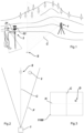
- Figure 1 shows a typical stake-out situation.
- a total station 1 is placed in a referenced position and the telescope of the total station 1 is precisely aligned horizontally to point towards the point S to be staked out.
- the centre of the field of view of the telescope and/or the centre of the field of view of the sensor comprised by the total station is indicated with the vertical plane C.
- the plane C is hence representing the horizontal component of the targeting direction of the total station.
- the sensor is embodied as a camera, wherein further elements such as magnification optics may be comprised.
- the sensor can be a sensor of another type, such as infrared sensor, an ultrasonic sensor, a RADAR or LIDAR sensor, a thermal detector, etc.
- Said output device 21 belongs to the guidance system and is in this example mounted on the stake-out device 2.
- the output device 21 could however also be embodied as a separate device external to the pole 21, e.g. as ear plugs, as a smart watch, or as any such kind of accessory which can provide signals easily perceivable for the user.
- the guidance system is configured for generating guidance data based on sensor data generated by the sensor, wherein the computer can be a computer that is already comprised by the total station 1, or a computer as a separate unit attachable to or comprised by the total station 1, by the stake-out device 2, or by an external device such as a server or a controller device.
- the sensor data from the sensor are sent to the guidance computer, and the guidance data are sent to the output device 21 and are "translated" into guidance signals.
- Data transfer between the sensor and the guidance computer, and between the guidance computer and the output device is in each case ensured by a connection system.
- a connection system comprises corresponding transmitters and receivers which are based on wireless technologies like wireless local area network, radio link, Bluetooth, etc., or the connection system provides appropriate cable connections.
- the output device 21 is thus connected to said guidance computer for receiving the guidance data and can output the guidance signals derived from the guidance data as acoustic, haptic, or visual signals.
- the output device 21 can comprise at least one of an acoustic indicator (e.g. a loudspeaker), a haptic indicator (e.g. a vibrating force-feedback handle), and a visual indicator (e.g. one or more lamps).
- the output device 21 is configured to receive the guidance signals wirelessly.
- the output device 21 could have a wired (but alternatively also a wireless) connection with the guidance computer.
- the stake-out device 2 further comprises a reflector 22, in this embodiment: a retro-reflector, which is precisely measurable by the measuring beam of the distance meter comprised by the target unit of the total station 1, and which is detectable by the sensor via a light emitted by a light source which is, in this embodiment, comprised by the total station 1.
- the reflector can also be embodied as a reflector disc.
- the reflector is adapted to the sensor in that it reflects what the sensor is sensitive for, i.e. for example visible radiation, infra-red radiation, ultra-violet radiation, sound waves, heat waves, etc.
- the total station does not need to comprise such light source in order to allow the sensor to detect the reflector.
- the reflector, the stake-out device, the user carrying the stake-out device, or any other gadget held by the stake-out device or the user could be detected by the sensor without such light source.
- the sensor data generated by the sensor are indicative for a position of the reflector, the stake-out device, the user carrying the stake-out device, or any other gadget held by the stake-out device or the user.
- the sensor data are indicative for said position relative to the centre line C, i.e. the target line of the target unit or in other words: the horizontal alignment of the target unit.
- the sensor data could be generated based on feature recognition algorithms or other signal analyses.
- the senor may be an on-axis-camera with an optical axis aligned with the measurement beam axis of the distance meter, or an off-axis-camera with a known relative pose with regard to the distance meter (e.g. the pose of the off-axis-camera can be such that its optical axis is essentially parallel to the beam axis).
- the reflector In case the reflector is located within the detection range of the camera and a light is emitted by the light source, a reflection of said light from said reflector is depicted in images captured by the sensor.
- the sensor data can be embodied as such images or derivatives from such images.
- An image sensor 1100 (see figure 3 ) of the camera is sensitive to the wavelength of the light emitted by the light source and it is therefore configured for detecting reflections of the light.
- the reflections D of the light backscattered from the reflector 22 and detected on the image sensor 1100 of the camera are used by the guidance system to generate the guidance data.
- said guidance signals depend on the pixel distance between the detected reflection D on the sensor 1100 and the centre pixels (plane C).
- Figure 2 shows the situation of figure 1 and 3 from a top view.
- the stake-out device 2 is located within the detection range F of the camera but offset from its centre plane C, which runs through the point S to be staked out.
- An exemplary work flow is as follows (with references to the system embodiment of figures 1, 2, and 3 ).
- the telescope of the total station is aimed at the desired horizontal reference angle. In other words, the telescope is targeted towards the vertical over the point S to be staked out.
- the user could confirm this status with a user interface of or connected to the total station.
- the guidance system can in response be activated and wait for the camera to output a detection of the reflector (sensor data).
- the invention improves not only ergonomics and accuracy but also safety.
- the output device 21 could output different kinds of sounds, vibrations, and/or simple light signals to indicate different degrees of approximation with regard to the centre plane C.
- the guidance signals may also comprise indications whether the sought centre is left or right from the user, wherein the terms "left” and "right” refer to a notional perspective of the user facing (at least approximately) in the direction of the total station.
- a signal for guiding the user to go more to the right would mean that he would need to continue walking forwards for reaching the centre. The user can easily arrive at this conclusion because he knows that the total station 1 is located left from him.
- the guidance system can also be configured (e.g. by comprising appropriate inertial sensors such as magnetometers, accelerometers, or gyroscopes) to track a current movement direction of the stake-out device, wherein the guidance computer is configured for generating the guidance data based further on the tracked current movement direction.
- the guidance signal could be a voice message such as "continue straight".
- the guidance system can derive whether the reflector is right or left from the centre plane C. Accordingly, the guidance data are generated to communicate this to the user. For example, a horizontal pixel distance is determined on the image sensor 1100 between the detected reflection D and the centre line C which act as reference pixels.
- a guidance signal is a spoken voice command "move to the right".
- the guidance system can also conclude from a sequence of detected reflections D whether the user is currently moving towards or away from the centre.
- the signal could in this case also be a spoken voice command like "continue straight” or "go back”.
- tone output in particular a different tone for each direction.
- the user would recognise e.g. from the tone colour in which direction to go.
- each of the two tones can sound in a varying loudness depending on how far the reflector is away from the centre (determinable with the distance between the reflection D and the centre line C on the image sensor 1100).
- the guidance signals can be a sequence of beep sounds, wherein the intervals between the sounds differ based on the distance between the retro-reflector and the centre.
- This sound scheme is similar to known parking assistants in automobiles.
- Another example is a permanent sound that changes its tone colour in dependence of the distance between the retro-reflector and the centre plane.
- the output device 21 comprises a haptic indicator (e.g. force-feedback handle), this haptic indicator can output vibrations in different frequencies, intervals, intensities, etc.
- a haptic indicator e.g. force-feedback handle
- the handle could vibrate at different places of the handle, therewith e.g. indicating the user that the centre is more to the right with respect to the total station by vibrating on the right part of the handle.
- the stake-out device 2 has a standard orientation, i.e. it is always held by the user in the same alignment and the stake-out system is configured to assume that the total station is facing usually one of the left and right side of the stake-out device (e.g. always the left side as depicted in Figure 1 ).
- the output device 21 comprises a lamp as a visual indicator, said lamp can output light signals in different frequencies, intervals, intensities, colours, etc.
- the lamp could give light at different places of the lamp, therewith e.g. indicating to the user that the centre is more to the right from a perspective facing the total station by activating a light source on the right part of the lamp.
- the stake-out device 2 has a standard orientation and that it is assumed that the user has a predefined rough orientation relative to the total station.
- the output device 21 can output a special, i.e. distinguishable signal when the reflector is exactly in line with the centre of the target unit of the total station.
- a special i.e. distinguishable signal
- the output device 21 could output said special signal or another special signal, clearly distinguishable from the other signals.
- the provision of the threshold range can make the user aware of him being very close to the centre plane C such that he will take further approaching attempts slower and more precise.
- the telescope of the total station 1 would be pitched by the user of the total station in order to find the reflector with the distance meter.
- the guidance system could further be configured for generating guidance signals to the output device 30 to indicate to the user to come closer towards the total station or to step back with signals distinguishable from the signals regarding the left/right direction as mentioned above.
- the sensor keeps track of said deviation and feed the guidance system with the needed input. With that, the guidance system guides the user back towards the centre.
Landscapes
- Physics & Mathematics (AREA)
- Engineering & Computer Science (AREA)
- General Physics & Mathematics (AREA)
- Radar, Positioning & Navigation (AREA)
- Remote Sensing (AREA)
- Optical Radar Systems And Details Thereof (AREA)
Claims (15)
- Geodätisches Absteckungssystem, umfassend eine Absteckungsvorrichtung, eine Totalstation und ein Leitsystem,wobei die Absteckungsvorrichtung Folgendes umfasst:- einen Reflektor und- eine Zeigespitze mit einer definierten Position in Bezug auf den Reflektor,wobei die Totalstation Folgendes umfasst:- eine Zieleinheit, die ein Teleskop, einen Abstandsmesser und einen Sensor umfasst; und- eine Richtungsmesseinheit, die dazu konfiguriert ist, eine horizontale und vertikale Drehposition der Zieleinheit zu messen,wobei die Zieleinheit dazu konfiguriert ist, horizontal und vertikal drehbar zu sein,wobei der Sensor dazu konfiguriert ist, Sensordaten zu erzeugen, undwobei die Sensordaten eine Position der Absteckungsvorrichtung angeben,wobei das Leitsystem Folgendes umfasst:- einen Leitcomputer, der dazu konfiguriert ist, Leitdaten auf Grundlage der Sensordaten zu erzeugen, und- eine Ausgabevorrichtung, die an der Absteckungsvorrichtung montiert und dazu konfiguriert ist, ein Leitsignal auf Grundlage der Leitdaten bereitzustellen, und- ein Verbindungssystem, das dazu konfiguriert ist, den Sensor mit dem Leitcomputer und den Leitcomputer mit der Ausgabevorrichtung zu verbinden,dadurch gekennzeichnet, dass das Teleskop dazu konfiguriert ist, derart ausgerichtet zu werden, dass eine Zielrichtung der Totalstation horizontal auf einen abzusteckenden Punkt gerichtet ist, und dass das Leitsignal dazu konfiguriert ist, einen Benutzer der Absteckungsvorrichtung zu einer horizontalen Mitte des Sichtfeldes des Teleskops zu leiten.
- Geodätisches Absteckungssystem nach Anspruch 1,wobei die Totalstation Folgendes umfasst:- eine Lichtquelle,wobei der Sensor dazu konfiguriert ist, Reflexionen des Lichts zu detektieren, das von der Lichtquelle emittiert wird, undwobei die Sensordaten einen relativen Ort einer durch den Reflektor verursachten detektierten Reflexion an dem Sensor umfassen.
- Geodätisches Absteckungssystem nach Anspruch 2,wobei das Leitsystem dazu konfiguriert ist, den relativen Ort der detektierten Reflexion als horizontalen Abstand zwischen der detektierten Reflexion und einer Referenz an dem Sensor zu bestimmen, undwobei der Referenzort des Sensors mindestens eine horizontale Zielrichtung des Abstandsmessers darstellt.
- Geodätisches Absteckungssystem nach einem der Ansprüche 2 und 3,
wobei das Erzeugen der Leitdaten auf einer Sequenz von mindestens zwei relativen Orten von jeweiligen durch den Reflektor verursachten detektierten Reflexionen an dem Sensor basiert, wobei die Sequenz eine Bewegungsrichtung des Reflektors angibt. - Geodätisches Absteckungssystem nach Anspruch 4,
wobei die Ausgabevorrichtung dazu konfiguriert ist, eine Sequenz von Leitsignalen bereitzustellen, wobei die Leitsignale der Sequenz in Bezug auf mindestens eines von einer Frequenz, einer Intensität, einer Dauer, eines Ortes innerhalb der Ausgabevorrichtung und einer Wellenlänge auf Grundlage der Sequenz der mindestens zwei relativen Orte von jeweiligen durch den Reflektor verursachten detektierten Reflexionen an dem Sensor variabel sind. - Geodätisches Absteckungssystem nach einem der vorhergehenden Ansprüche,wobei die Ausgabevorrichtung einen akustischen Indikator umfasst,wobei das Leitsignal ein akustisches Signal umfasst.
- Geodätisches Absteckungssystem nach einem der vorhergehenden Ansprüche,wobei die Ausgabevorrichtung einen haptischen Indikator umfasst,wobei das Leitsignal ein haptisches Signal umfasst.
- Geodätisches Absteckungssystem nach einem der vorhergehenden Ansprüche,wobei die Ausgabevorrichtung einen visuellen Indikator umfasst,wobei das Leitsignal ein visuelles Signal umfasst.
- Geodätisches Absteckungssystem nach einem der vorhergehenden Ansprüche,
wobei die Ausgabevorrichtung dazu konfiguriert ist, ein spezielles Leitsignal bereitzustellen, wenn ein Wert des relativen Ortes des Retroreflektors innerhalb eines vordefinierten Schwellenbereichs liegt. - Geodätisches Absteckungssystem nach einem der vorhergehenden Ansprüche,
wobei das Erzeugen der Leitdaten ferner auf einer Abstandsmessung mit dem Abstandsmesser basiert. - Absteckungsverfahren mit einem geodätischen Absteckungssystem, wobei das Verfahren Folgendes umfasst:- Ausrichten eines Teleskops, das in einer Zieleinheit einer Totalstation enthalten ist, sodass eine Zielrichtung der Totalstation horizontal auf einen abzusteckenden Punkt gerichtet ist,- Bewegen einer Absteckungsvorrichtung in ein Sichtfeld eines Sensors, der in der Zieleinheit enthalten ist,- Erzeugen von Sensordaten mit dem Sensor, wobei die Sensordaten eine Position der Absteckungsvorrichtung angeben,- Empfangen der Sensordaten mit einem Leitcomputer,- Erzeugen von Leitdaten mit dem Leitcomputer auf Grundlage der Sensordaten,- Empfangen der Leitdaten mit einer Ausgabevorrichtung, die an der Absteckungsvorrichtung montiert ist, und- Bereitstellen eines Leitsignals mit der Ausgabevorrichtung auf Grundlage der Leitdaten, dadurch gekennzeichnet, dasseine Zielrichtung der Totalstation horizontal auf einen abzusteckenden Punkt gerichtet ist und das Leitsignal einen Benutzer der Absteckungsvorrichtung zu einer horizontalen Mitte des Sichtfeldes des Teleskops leitet.
- Absteckungsverfahren nach Anspruch 11, umfassend- Emittieren eines Lichts mit einer Lichtquelle, die in der Totalstation enthalten ist,- Detektieren von Reflexionen des Lichts mit dem Sensor,wobei die Sensordaten einen relativen Ort einer durch den Retroreflektor verursachten detektierten Reflexion an dem Sensor umfassen.
- Absteckungsverfahren nach einem der Ansprüche 11 und 12,wobei das Leitsignal ein akustisches Signal umfasst,wobei das akustische Signal mit einem akustischen Indikator ausgegeben wird, der in der Ausgabevorrichtung enthalten ist.
- Absteckungsverfahren nach einem der Ansprüche 11 und 13,wobei das Leitsignal ein haptisches Signal umfasst,wobei das haptische Signal mit einem haptischen Indikator ausgegeben wird, der in der Ausgabevorrichtung enthalten ist.
- Absteckungsverfahren nach einem der Ansprüche 11 und 14,wobei das Leitsignal ein visuelles Signal umfasst,wobei das visuelle Signal mit einem visuellen Indikator ausgegeben wird, der in der Ausgabevorrichtung enthalten ist.
Priority Applications (3)
| Application Number | Priority Date | Filing Date | Title |
|---|---|---|---|
| EP18213004.7A EP3671115B1 (de) | 2018-12-17 | 2018-12-17 | Geodätisches absteckungssystem |
| US16/704,232 US20200191569A1 (en) | 2018-12-17 | 2019-12-05 | Geodetic stake-out system |
| CN201911264092.3A CN111322995A (zh) | 2018-12-17 | 2019-12-11 | 大地测量放样系统 |
Applications Claiming Priority (1)
| Application Number | Priority Date | Filing Date | Title |
|---|---|---|---|
| EP18213004.7A EP3671115B1 (de) | 2018-12-17 | 2018-12-17 | Geodätisches absteckungssystem |
Publications (2)
| Publication Number | Publication Date |
|---|---|
| EP3671115A1 EP3671115A1 (de) | 2020-06-24 |
| EP3671115B1 true EP3671115B1 (de) | 2023-10-11 |
Family
ID=64744410
Family Applications (1)
| Application Number | Title | Priority Date | Filing Date |
|---|---|---|---|
| EP18213004.7A Active EP3671115B1 (de) | 2018-12-17 | 2018-12-17 | Geodätisches absteckungssystem |
Country Status (3)
| Country | Link |
|---|---|
| US (1) | US20200191569A1 (de) |
| EP (1) | EP3671115B1 (de) |
| CN (1) | CN111322995A (de) |
Families Citing this family (3)
| Publication number | Priority date | Publication date | Assignee | Title |
|---|---|---|---|---|
| EP3583385B1 (de) * | 2017-02-14 | 2021-04-21 | Trimble AB | Geodätische vermessung mit zeitsynchronisation |
| CN111854712B (zh) * | 2020-07-29 | 2021-03-02 | 北京龙软科技股份有限公司 | 自动测量综采工作面目标点坐标的方法和测量机器人系统 |
| US20250012569A1 (en) * | 2023-07-03 | 2025-01-09 | Carter & Clark, LLC | Systems and Methods for Determining a Boundary for a Real Estate Parcel Based Upon Signals from a Beacon Apparatus |
Citations (1)
| Publication number | Priority date | Publication date | Assignee | Title |
|---|---|---|---|---|
| EP2105705A1 (de) * | 2008-03-25 | 2009-09-30 | Kabushiki Kaisha Topcon | Vermessungssystem |
Family Cites Families (13)
| Publication number | Priority date | Publication date | Assignee | Title |
|---|---|---|---|---|
| SE464782B (sv) * | 1987-12-22 | 1991-06-10 | Geotronics Ab | Anordning vid ett avstaandsmaetningsinstrument saasom hjaelpmedel vid utsaettning |
| US7073268B1 (en) * | 2002-04-18 | 2006-07-11 | Black & Decker Inc. | Level apparatus |
| EP1734336A1 (de) * | 2005-06-13 | 2006-12-20 | Leica Geosystems AG | Geodätisches Zielobjekt und Vermessungssystem |
| NL1036517C2 (nl) * | 2009-02-05 | 2010-08-10 | Holding Prodim Systems B V | Inrichting en werkwijze voor het uitzetten van contouren of werken en een meetinrichting en aanwijsinrichting ingericht voor gebruik hierbij. |
| US8537376B2 (en) * | 2011-04-15 | 2013-09-17 | Faro Technologies, Inc. | Enhanced position detector in laser tracker |
| CN103827631B (zh) * | 2011-09-27 | 2016-11-16 | 莱卡地球系统公开股份有限公司 | 对坐标系中已知的目标点进行标记的测量系统和方法 |
| CN103644899A (zh) * | 2013-12-06 | 2014-03-19 | 苏州迅威光电科技有限公司 | 一种全站仪的激光对中模块 |
| EP2916104B1 (de) * | 2014-03-07 | 2018-06-27 | Hexagon Technology Center GmbH | Reflektoranordnung mit Retroreflektor sowie mit Sensoranordnung zur Neigungsbestimmung und Kalibrierung |
| CN104165622A (zh) * | 2014-06-19 | 2014-11-26 | 苏州一光仪器有限公司 | 一种全站仪及放样测量装置 |
| JP6418889B2 (ja) * | 2014-10-20 | 2018-11-07 | 株式会社トプコン | 測量システムおよびこの測量システムに用いる携帯型無線送受信装置ならびに測量用ポール。 |
| JP6630515B2 (ja) * | 2015-08-25 | 2020-01-15 | 株式会社トプコン | 位置誘導装置、位置誘導方法、プログラム |
| CN108474653B (zh) * | 2016-01-20 | 2020-03-20 | 三菱电机株式会社 | 三维计测装置及其计测辅助处理方法 |
| CN106679638A (zh) * | 2016-12-20 | 2017-05-17 | 常州市新瑞得仪器有限公司 | 全站仪及其放样导向的方法 |
-
2018
- 2018-12-17 EP EP18213004.7A patent/EP3671115B1/de active Active
-
2019
- 2019-12-05 US US16/704,232 patent/US20200191569A1/en not_active Abandoned
- 2019-12-11 CN CN201911264092.3A patent/CN111322995A/zh active Pending
Patent Citations (1)
| Publication number | Priority date | Publication date | Assignee | Title |
|---|---|---|---|---|
| EP2105705A1 (de) * | 2008-03-25 | 2009-09-30 | Kabushiki Kaisha Topcon | Vermessungssystem |
Also Published As
| Publication number | Publication date |
|---|---|
| US20200191569A1 (en) | 2020-06-18 |
| EP3671115A1 (de) | 2020-06-24 |
| CN111322995A (zh) | 2020-06-23 |
Similar Documents
| Publication | Publication Date | Title |
|---|---|---|
| US9846029B2 (en) | Laser system with a laser receiver capable to detect its own movements | |
| KR102345919B1 (ko) | 라이다(lidar) 디바이스를 보호하기 위한 방법들 및 시스템들 | |
| US20250180748A1 (en) | Feature data structure, control device, storage device, control method, program and storage medium | |
| AU2009321623B2 (en) | Position determination method and geodetic measuring system | |
| EP3671115B1 (de) | Geodätisches absteckungssystem | |
| EP2639549A1 (de) | Laserempfänger | |
| CN105940316B (zh) | 传感器设备 | |
| US12174019B2 (en) | Laser device and laser beam detector for detecting light of a laser device | |
| JP2008292397A (ja) | 可視光通信を用いた位置情報提供システム | |
| WO2016031504A1 (ja) | 測設情報標示装置、測設情報標示方法 | |
| JP6177825B2 (ja) | 光電センサおよび監視領域から測定情報を検出するための方法 | |
| US20170219345A1 (en) | Device for automatically finding a mobile geodetic target object | |
| US12392892B2 (en) | Method for installing radio wave sensor, radio wave sensor, and adjustment device | |
| JP2001013247A (ja) | 自動測量システム | |
| KR20130093988A (ko) | 적외선 라인 레이저를 이용한 무인주행차량의 야간 주행 유도 시스템 및 방법 | |
| KR102270254B1 (ko) | 타겟의 초기 위치 감지 기능을 구비한 다변측량 레이저 추적 장치 및 추적 방법 | |
| JP2025013663A (ja) | 制御装置、サーバ装置、制御方法、及びプログラム | |
| KR102502155B1 (ko) | 음성 안내를 위한 보행 안내 장치 및 이의 동작 방법 | |
| KR101721932B1 (ko) | 길 안내 장치 및 그 제어 방법 | |
| KR102306280B1 (ko) | 컨트롤러 설정 장치 및 방법 | |
| JP2007049240A (ja) | 光軸調整装置及び光軸調整方法 | |
| JPH09101150A (ja) | ポイント設定用レーダ装置 | |
| CN105552995A (zh) | 一种充电装置、电子设备、控制方法及系统 |
Legal Events
| Date | Code | Title | Description |
|---|---|---|---|
| PUAI | Public reference made under article 153(3) epc to a published international application that has entered the european phase |
Free format text: ORIGINAL CODE: 0009012 |
|
| STAA | Information on the status of an ep patent application or granted ep patent |
Free format text: STATUS: THE APPLICATION HAS BEEN PUBLISHED |
|
| AK | Designated contracting states |
Kind code of ref document: A1 Designated state(s): AL AT BE BG CH CY CZ DE DK EE ES FI FR GB GR HR HU IE IS IT LI LT LU LV MC MK MT NL NO PL PT RO RS SE SI SK SM TR |
|
| AX | Request for extension of the european patent |
Extension state: BA ME |
|
| STAA | Information on the status of an ep patent application or granted ep patent |
Free format text: STATUS: REQUEST FOR EXAMINATION WAS MADE |
|
| 17P | Request for examination filed |
Effective date: 20201215 |
|
| RBV | Designated contracting states (corrected) |
Designated state(s): AL AT BE BG CH CY CZ DE DK EE ES FI FR GB GR HR HU IE IS IT LI LT LU LV MC MK MT NL NO PL PT RO RS SE SI SK SM TR |
|
| STAA | Information on the status of an ep patent application or granted ep patent |
Free format text: STATUS: EXAMINATION IS IN PROGRESS |
|
| 17Q | First examination report despatched |
Effective date: 20220503 |
|
| GRAP | Despatch of communication of intention to grant a patent |
Free format text: ORIGINAL CODE: EPIDOSNIGR1 |
|
| STAA | Information on the status of an ep patent application or granted ep patent |
Free format text: STATUS: GRANT OF PATENT IS INTENDED |
|
| INTG | Intention to grant announced |
Effective date: 20230621 |
|
| GRAS | Grant fee paid |
Free format text: ORIGINAL CODE: EPIDOSNIGR3 |
|
| GRAA | (expected) grant |
Free format text: ORIGINAL CODE: 0009210 |
|
| STAA | Information on the status of an ep patent application or granted ep patent |
Free format text: STATUS: THE PATENT HAS BEEN GRANTED |
|
| AK | Designated contracting states |
Kind code of ref document: B1 Designated state(s): AL AT BE BG CH CY CZ DE DK EE ES FI FR GB GR HR HU IE IS IT LI LT LU LV MC MK MT NL NO PL PT RO RS SE SI SK SM TR |
|
| REG | Reference to a national code |
Ref country code: GB Ref legal event code: FG4D |
|
| REG | Reference to a national code |
Ref country code: CH Ref legal event code: EP |
|
| REG | Reference to a national code |
Ref country code: DE Ref legal event code: R096 Ref document number: 602018059089 Country of ref document: DE |
|
| REG | Reference to a national code |
Ref country code: IE Ref legal event code: FG4D |
|
| REG | Reference to a national code |
Ref country code: LT Ref legal event code: MG9D |
|
| REG | Reference to a national code |
Ref country code: NL Ref legal event code: MP Effective date: 20231011 |
|
| REG | Reference to a national code |
Ref country code: AT Ref legal event code: MK05 Ref document number: 1620617 Country of ref document: AT Kind code of ref document: T Effective date: 20231011 |
|
| PG25 | Lapsed in a contracting state [announced via postgrant information from national office to epo] |
Ref country code: NL Free format text: LAPSE BECAUSE OF FAILURE TO SUBMIT A TRANSLATION OF THE DESCRIPTION OR TO PAY THE FEE WITHIN THE PRESCRIBED TIME-LIMIT Effective date: 20231011 |
|
| PG25 | Lapsed in a contracting state [announced via postgrant information from national office to epo] |
Ref country code: GR Free format text: LAPSE BECAUSE OF FAILURE TO SUBMIT A TRANSLATION OF THE DESCRIPTION OR TO PAY THE FEE WITHIN THE PRESCRIBED TIME-LIMIT Effective date: 20240112 |
|
| PG25 | Lapsed in a contracting state [announced via postgrant information from national office to epo] |
Ref country code: IS Free format text: LAPSE BECAUSE OF FAILURE TO SUBMIT A TRANSLATION OF THE DESCRIPTION OR TO PAY THE FEE WITHIN THE PRESCRIBED TIME-LIMIT Effective date: 20240211 |
|
| PG25 | Lapsed in a contracting state [announced via postgrant information from national office to epo] |
Ref country code: LT Free format text: LAPSE BECAUSE OF FAILURE TO SUBMIT A TRANSLATION OF THE DESCRIPTION OR TO PAY THE FEE WITHIN THE PRESCRIBED TIME-LIMIT Effective date: 20231011 |
|
| PG25 | Lapsed in a contracting state [announced via postgrant information from national office to epo] |
Ref country code: AT Free format text: LAPSE BECAUSE OF FAILURE TO SUBMIT A TRANSLATION OF THE DESCRIPTION OR TO PAY THE FEE WITHIN THE PRESCRIBED TIME-LIMIT Effective date: 20231011 |
|
| PG25 | Lapsed in a contracting state [announced via postgrant information from national office to epo] |
Ref country code: ES Free format text: LAPSE BECAUSE OF FAILURE TO SUBMIT A TRANSLATION OF THE DESCRIPTION OR TO PAY THE FEE WITHIN THE PRESCRIBED TIME-LIMIT Effective date: 20231011 |
|
| PG25 | Lapsed in a contracting state [announced via postgrant information from national office to epo] |
Ref country code: LT Free format text: LAPSE BECAUSE OF FAILURE TO SUBMIT A TRANSLATION OF THE DESCRIPTION OR TO PAY THE FEE WITHIN THE PRESCRIBED TIME-LIMIT Effective date: 20231011 Ref country code: IS Free format text: LAPSE BECAUSE OF FAILURE TO SUBMIT A TRANSLATION OF THE DESCRIPTION OR TO PAY THE FEE WITHIN THE PRESCRIBED TIME-LIMIT Effective date: 20240211 Ref country code: GR Free format text: LAPSE BECAUSE OF FAILURE TO SUBMIT A TRANSLATION OF THE DESCRIPTION OR TO PAY THE FEE WITHIN THE PRESCRIBED TIME-LIMIT Effective date: 20240112 Ref country code: ES Free format text: LAPSE BECAUSE OF FAILURE TO SUBMIT A TRANSLATION OF THE DESCRIPTION OR TO PAY THE FEE WITHIN THE PRESCRIBED TIME-LIMIT Effective date: 20231011 Ref country code: BG Free format text: LAPSE BECAUSE OF FAILURE TO SUBMIT A TRANSLATION OF THE DESCRIPTION OR TO PAY THE FEE WITHIN THE PRESCRIBED TIME-LIMIT Effective date: 20240111 Ref country code: AT Free format text: LAPSE BECAUSE OF FAILURE TO SUBMIT A TRANSLATION OF THE DESCRIPTION OR TO PAY THE FEE WITHIN THE PRESCRIBED TIME-LIMIT Effective date: 20231011 Ref country code: PT Free format text: LAPSE BECAUSE OF FAILURE TO SUBMIT A TRANSLATION OF THE DESCRIPTION OR TO PAY THE FEE WITHIN THE PRESCRIBED TIME-LIMIT Effective date: 20240212 |
|
| PG25 | Lapsed in a contracting state [announced via postgrant information from national office to epo] |
Ref country code: SE Free format text: LAPSE BECAUSE OF FAILURE TO SUBMIT A TRANSLATION OF THE DESCRIPTION OR TO PAY THE FEE WITHIN THE PRESCRIBED TIME-LIMIT Effective date: 20231011 Ref country code: RS Free format text: LAPSE BECAUSE OF FAILURE TO SUBMIT A TRANSLATION OF THE DESCRIPTION OR TO PAY THE FEE WITHIN THE PRESCRIBED TIME-LIMIT Effective date: 20231011 Ref country code: PL Free format text: LAPSE BECAUSE OF FAILURE TO SUBMIT A TRANSLATION OF THE DESCRIPTION OR TO PAY THE FEE WITHIN THE PRESCRIBED TIME-LIMIT Effective date: 20231011 Ref country code: NO Free format text: LAPSE BECAUSE OF FAILURE TO SUBMIT A TRANSLATION OF THE DESCRIPTION OR TO PAY THE FEE WITHIN THE PRESCRIBED TIME-LIMIT Effective date: 20240111 Ref country code: LV Free format text: LAPSE BECAUSE OF FAILURE TO SUBMIT A TRANSLATION OF THE DESCRIPTION OR TO PAY THE FEE WITHIN THE PRESCRIBED TIME-LIMIT Effective date: 20231011 Ref country code: HR Free format text: LAPSE BECAUSE OF FAILURE TO SUBMIT A TRANSLATION OF THE DESCRIPTION OR TO PAY THE FEE WITHIN THE PRESCRIBED TIME-LIMIT Effective date: 20231011 |
|
| PG25 | Lapsed in a contracting state [announced via postgrant information from national office to epo] |
Ref country code: DK Free format text: LAPSE BECAUSE OF FAILURE TO SUBMIT A TRANSLATION OF THE DESCRIPTION OR TO PAY THE FEE WITHIN THE PRESCRIBED TIME-LIMIT Effective date: 20231011 |
|
| REG | Reference to a national code |
Ref country code: DE Ref legal event code: R097 Ref document number: 602018059089 Country of ref document: DE |
|
| PG25 | Lapsed in a contracting state [announced via postgrant information from national office to epo] |
Ref country code: CZ Free format text: LAPSE BECAUSE OF FAILURE TO SUBMIT A TRANSLATION OF THE DESCRIPTION OR TO PAY THE FEE WITHIN THE PRESCRIBED TIME-LIMIT Effective date: 20231011 |
|
| PG25 | Lapsed in a contracting state [announced via postgrant information from national office to epo] |
Ref country code: SK Free format text: LAPSE BECAUSE OF FAILURE TO SUBMIT A TRANSLATION OF THE DESCRIPTION OR TO PAY THE FEE WITHIN THE PRESCRIBED TIME-LIMIT Effective date: 20231011 |
|
| PG25 | Lapsed in a contracting state [announced via postgrant information from national office to epo] |
Ref country code: SM Free format text: LAPSE BECAUSE OF FAILURE TO SUBMIT A TRANSLATION OF THE DESCRIPTION OR TO PAY THE FEE WITHIN THE PRESCRIBED TIME-LIMIT Effective date: 20231011 Ref country code: SK Free format text: LAPSE BECAUSE OF FAILURE TO SUBMIT A TRANSLATION OF THE DESCRIPTION OR TO PAY THE FEE WITHIN THE PRESCRIBED TIME-LIMIT Effective date: 20231011 Ref country code: RO Free format text: LAPSE BECAUSE OF FAILURE TO SUBMIT A TRANSLATION OF THE DESCRIPTION OR TO PAY THE FEE WITHIN THE PRESCRIBED TIME-LIMIT Effective date: 20231011 Ref country code: IT Free format text: LAPSE BECAUSE OF FAILURE TO SUBMIT A TRANSLATION OF THE DESCRIPTION OR TO PAY THE FEE WITHIN THE PRESCRIBED TIME-LIMIT Effective date: 20231011 Ref country code: EE Free format text: LAPSE BECAUSE OF FAILURE TO SUBMIT A TRANSLATION OF THE DESCRIPTION OR TO PAY THE FEE WITHIN THE PRESCRIBED TIME-LIMIT Effective date: 20231011 Ref country code: DK Free format text: LAPSE BECAUSE OF FAILURE TO SUBMIT A TRANSLATION OF THE DESCRIPTION OR TO PAY THE FEE WITHIN THE PRESCRIBED TIME-LIMIT Effective date: 20231011 Ref country code: CZ Free format text: LAPSE BECAUSE OF FAILURE TO SUBMIT A TRANSLATION OF THE DESCRIPTION OR TO PAY THE FEE WITHIN THE PRESCRIBED TIME-LIMIT Effective date: 20231011 |
|
| PLBE | No opposition filed within time limit |
Free format text: ORIGINAL CODE: 0009261 |
|
| STAA | Information on the status of an ep patent application or granted ep patent |
Free format text: STATUS: NO OPPOSITION FILED WITHIN TIME LIMIT |
|
| PG25 | Lapsed in a contracting state [announced via postgrant information from national office to epo] |
Ref country code: LU Free format text: LAPSE BECAUSE OF NON-PAYMENT OF DUE FEES Effective date: 20231217 |
|
| PG25 | Lapsed in a contracting state [announced via postgrant information from national office to epo] |
Ref country code: MC Free format text: LAPSE BECAUSE OF FAILURE TO SUBMIT A TRANSLATION OF THE DESCRIPTION OR TO PAY THE FEE WITHIN THE PRESCRIBED TIME-LIMIT Effective date: 20231011 |
|
| REG | Reference to a national code |
Ref country code: BE Ref legal event code: MM Effective date: 20231231 |
|
| PG25 | Lapsed in a contracting state [announced via postgrant information from national office to epo] |
Ref country code: MC Free format text: LAPSE BECAUSE OF FAILURE TO SUBMIT A TRANSLATION OF THE DESCRIPTION OR TO PAY THE FEE WITHIN THE PRESCRIBED TIME-LIMIT Effective date: 20231011 Ref country code: LU Free format text: LAPSE BECAUSE OF NON-PAYMENT OF DUE FEES Effective date: 20231217 |
|
| 26N | No opposition filed |
Effective date: 20240712 |
|
| REG | Reference to a national code |
Ref country code: IE Ref legal event code: MM4A |
|
| PG25 | Lapsed in a contracting state [announced via postgrant information from national office to epo] |
Ref country code: IE Free format text: LAPSE BECAUSE OF NON-PAYMENT OF DUE FEES Effective date: 20231217 |
|
| PG25 | Lapsed in a contracting state [announced via postgrant information from national office to epo] |
Ref country code: BE Free format text: LAPSE BECAUSE OF NON-PAYMENT OF DUE FEES Effective date: 20231231 |
|
| PG25 | Lapsed in a contracting state [announced via postgrant information from national office to epo] |
Ref country code: SI Free format text: LAPSE BECAUSE OF FAILURE TO SUBMIT A TRANSLATION OF THE DESCRIPTION OR TO PAY THE FEE WITHIN THE PRESCRIBED TIME-LIMIT Effective date: 20231011 |
|
| PG25 | Lapsed in a contracting state [announced via postgrant information from national office to epo] |
Ref country code: SI Free format text: LAPSE BECAUSE OF FAILURE TO SUBMIT A TRANSLATION OF THE DESCRIPTION OR TO PAY THE FEE WITHIN THE PRESCRIBED TIME-LIMIT Effective date: 20231011 Ref country code: IE Free format text: LAPSE BECAUSE OF NON-PAYMENT OF DUE FEES Effective date: 20231217 Ref country code: BE Free format text: LAPSE BECAUSE OF NON-PAYMENT OF DUE FEES Effective date: 20231231 |
|
| PG25 | Lapsed in a contracting state [announced via postgrant information from national office to epo] |
Ref country code: FI Free format text: LAPSE BECAUSE OF FAILURE TO SUBMIT A TRANSLATION OF THE DESCRIPTION OR TO PAY THE FEE WITHIN THE PRESCRIBED TIME-LIMIT Effective date: 20231011 |
|
| PG25 | Lapsed in a contracting state [announced via postgrant information from national office to epo] |
Ref country code: CY Free format text: LAPSE BECAUSE OF FAILURE TO SUBMIT A TRANSLATION OF THE DESCRIPTION OR TO PAY THE FEE WITHIN THE PRESCRIBED TIME-LIMIT; INVALID AB INITIO Effective date: 20181217 |
|
| PG25 | Lapsed in a contracting state [announced via postgrant information from national office to epo] |
Ref country code: HU Free format text: LAPSE BECAUSE OF FAILURE TO SUBMIT A TRANSLATION OF THE DESCRIPTION OR TO PAY THE FEE WITHIN THE PRESCRIBED TIME-LIMIT; INVALID AB INITIO Effective date: 20181217 |
|
| PG25 | Lapsed in a contracting state [announced via postgrant information from national office to epo] |
Ref country code: TR Free format text: LAPSE BECAUSE OF FAILURE TO SUBMIT A TRANSLATION OF THE DESCRIPTION OR TO PAY THE FEE WITHIN THE PRESCRIBED TIME-LIMIT Effective date: 20231011 |
|
| REG | Reference to a national code |
Ref country code: CH Ref legal event code: U11 Free format text: ST27 STATUS EVENT CODE: U-0-0-U10-U11 (AS PROVIDED BY THE NATIONAL OFFICE) Effective date: 20260101 |
|
| PGFP | Annual fee paid to national office [announced via postgrant information from national office to epo] |
Ref country code: DE Payment date: 20251211 Year of fee payment: 8 |
|
| PGFP | Annual fee paid to national office [announced via postgrant information from national office to epo] |
Ref country code: GB Payment date: 20251219 Year of fee payment: 8 |
|
| PGFP | Annual fee paid to national office [announced via postgrant information from national office to epo] |
Ref country code: FR Payment date: 20251229 Year of fee payment: 8 |
|
| PGFP | Annual fee paid to national office [announced via postgrant information from national office to epo] |
Ref country code: CH Payment date: 20260101 Year of fee payment: 8 |