EP3671118B1 - Gyroscope multiaxial anti-vibration - Google Patents
Gyroscope multiaxial anti-vibration Download PDFInfo
- Publication number
- EP3671118B1 EP3671118B1 EP19209901.8A EP19209901A EP3671118B1 EP 3671118 B1 EP3671118 B1 EP 3671118B1 EP 19209901 A EP19209901 A EP 19209901A EP 3671118 B1 EP3671118 B1 EP 3671118B1
- Authority
- EP
- European Patent Office
- Prior art keywords
- proof mass
- quartet
- proof
- center point
- axis
- Prior art date
- Legal status (The legal status is an assumption and is not a legal conclusion. Google has not performed a legal analysis and makes no representation as to the accuracy of the status listed.)
- Active
Links
Images






Classifications
-
- G—PHYSICS
- G01—MEASURING; TESTING
- G01C—MEASURING DISTANCES, LEVELS OR BEARINGS; SURVEYING; NAVIGATION; GYROSCOPIC INSTRUMENTS; PHOTOGRAMMETRY OR VIDEOGRAMMETRY
- G01C19/00—Gyroscopes; Turn-sensitive devices using vibrating masses; Turn-sensitive devices without moving masses; Measuring angular rate using gyroscopic effects
- G01C19/56—Turn-sensitive devices using vibrating masses, e.g. vibratory angular rate sensors based on Coriolis forces
- G01C19/567—Turn-sensitive devices using vibrating masses, e.g. vibratory angular rate sensors based on Coriolis forces using the phase shift of a vibration node or antinode
- G01C19/5677—Turn-sensitive devices using vibrating masses, e.g. vibratory angular rate sensors based on Coriolis forces using the phase shift of a vibration node or antinode of essentially two-dimensional [2D] vibrators, e.g. ring-shaped vibrators
- G01C19/5684—Turn-sensitive devices using vibrating masses, e.g. vibratory angular rate sensors based on Coriolis forces using the phase shift of a vibration node or antinode of essentially two-dimensional [2D] vibrators, e.g. ring-shaped vibrators the devices involving a micromechanical structure
-
- G—PHYSICS
- G01—MEASURING; TESTING
- G01C—MEASURING DISTANCES, LEVELS OR BEARINGS; SURVEYING; NAVIGATION; GYROSCOPIC INSTRUMENTS; PHOTOGRAMMETRY OR VIDEOGRAMMETRY
- G01C19/00—Gyroscopes; Turn-sensitive devices using vibrating masses; Turn-sensitive devices without moving masses; Measuring angular rate using gyroscopic effects
- G01C19/56—Turn-sensitive devices using vibrating masses, e.g. vibratory angular rate sensors based on Coriolis forces
- G01C19/5719—Turn-sensitive devices using vibrating masses, e.g. vibratory angular rate sensors based on Coriolis forces using planar vibrating masses driven in a translation vibration along an axis
- G01C19/5733—Structural details or topology
- G01C19/574—Structural details or topology the devices having two sensing masses in anti-phase motion
-
- G—PHYSICS
- G01—MEASURING; TESTING
- G01C—MEASURING DISTANCES, LEVELS OR BEARINGS; SURVEYING; NAVIGATION; GYROSCOPIC INSTRUMENTS; PHOTOGRAMMETRY OR VIDEOGRAMMETRY
- G01C19/00—Gyroscopes; Turn-sensitive devices using vibrating masses; Turn-sensitive devices without moving masses; Measuring angular rate using gyroscopic effects
- G01C19/02—Rotary gyroscopes
- G01C19/04—Details
- G01C19/16—Suspensions; Bearings
- G01C19/22—Suspensions; Bearings torsional
Definitions
- This disclosure relates to microelectromechanical gyroscopes, and more particularly to multiaxis gyroscopes where the same oscillating proof mass system can be used for measuring angular rotation about one, two or three mutually perpendicular rotations axes.
- MEMS microelectromechanical
- gyroscopes utilizing oscillating proof masses
- the masses should preferably be easily driven into a primary oscillation mode (which may also be called the drive oscillation mode) by drive actuators and also be easily set into a secondary oscillation mode (which may also be called the sense oscillation mode) by the Coriolis force, but still preferably not be moved by external disturbances.
- a gyroscope should preferably be unperturbed by linear and rotational vibrations imparted to it by surrounding elements at frequencies that are above the measurement frequency range, so that its output signal is determined only by the angular rotation rate which the gyroscope undergoes within the intended measurement frequency range.
- the disturbing vibrations typically lie in the frequency range 1...50 kHz, whereas the measurement frequency range is typically below 1 kHz.
- a simple MEMS gyroscope may be constructed utilizing only one oscillating proof mass, but its output signal will typically be very noisy if external vibrations are present at a frequency close to the oscillating frequency of the gyroscope.
- Such a gyroscope is practical only at oscillation frequencies above 50 kHz where the sensitivity of the gyroscope may be very low and other disturbing effects, such as quadrature signals that arise from manufacturing imperfections, may become very prominent.
- a proof mass system where two or four proof masses oscillate in anti-phase can be made much more robust than a one-mass gyroscope because signal components arising from vibrations that induce cophasal movement of the two or four proof masses can be automatically cancelled to some degree via differential measurements.
- the cophasal resonant frequency can be brought above 50 kHz without affecting the differential resonant frequency, the gyroscope may be very robust to external vibrations since there is no resonance amplification for the disturbing vibrations.
- MEMS gyroscopes are designed for measuring rotation rate about one axis which is perpendicular to the device substrate. Such gyroscopes may be called z-axis gyroscopes. Other MEMS gyroscopes are designed for measuring rotation rate about either of the two perpendicular axes which lie within the substrate plane. Such gyroscopes may be called x-axis gyroscopes and/or y-axis gyroscopes.
- a multi-axis gyroscope can be created by incorporating two or three one-axis gyroscopes for different axes of rotation in the same device. This kind of multi-axis gyroscope will have two or three discrete oscillation frequencies, which will make the design of the electronic circuit difficult in order to avoid interference between the frequencies. Multiple sustaining and stabilizing circuits are then also needed for the primary oscillation. Some multiaxis MEMS gyroscopes are designed for measuring rotation rate about the x-, y-, and/or z-axis with the same set of oscillating proof masses to avoid the possible interference between different frequencies.
- Document US2015128700 discloses a multiaxis gyroscope with a proof mass system which utilizes eight masses symmetrically located around a common center so that in a radial configuration four masses are inner masses and four masses are outer masses or, in a stacked configuration, so that four masses are upper masses and four masses are lower masses. In either configuration it is not easy to conceive suspension and coupling arrangements, which would allow all desired oscillation modes and suppress all undesired modes and no such arrangements are presented in US2015128700 .
- An object of this disclosure is to provide an apparatus for alleviating the above disadvantages and present multiaxis gyroscopes with proof mass systems that more efficiently promote desired modes and suppress undesired modes, and also allows the most advantageous operation modes and vibration modes of the proof masses to be used.
- the object of the disclosure is achieved by an arrangement which is characterized by what is stated in the independent claim.
- the preferred embodiment of the disclosure is disclosed in the dependent claim.
- the disclosure is based on the idea of utilizing a proof mass system which comprises two adjacent proof mass quartets.
- the primary oscillation mode is actuated so that each proof mass in a quartet oscillates, in relation to its quartet center point, in anti-phase compared to the corresponding proof mass in the other quartet.
- An advantage of the arrangement presented in this disclosure is that oscillation modes can be easily synchronized and suppressed, which makes the gyroscope robust against external vibrations.
- Side-by-side placement of two proof mass quartets allows easy interconnection between two proof masses in the middle of the gyroscope, which move essentially in-phase in all oscillation modes.
- other proof masses in the proof masses quartets may be interconnected with a see-saw or lever structure, since they move in anti-phase in all oscillation modes.
- This disclosure describes a microelectromechanical gyroscope which comprises a first proof mass quartet and a second proof mass quartet in a device plane, with a corresponding first quartet center point and a corresponding second quartet center point which lie on a lateral axis.
- the four proof masses which form the first proof mass quartet are in their rest position symmetrically arranged around the first quartet center point where the lateral axis crosses a first transversal axis orthogonally in the device plane.
- the four proof masses which form the second proof mass quartet are in their rest position symmetrically arranged around the second quartet center point where the lateral axis crosses a second transversal axis orthogonally in the device plane.
- the first and second proof masses in each proof mass quartet are aligned on the lateral axis in their rest position, and third and fourth proof masses in the first proof mass quartet are aligned on the first transversal axis in their rest position.
- Third and fourth proof masses in the second proof mass quartet are aligned on the second transversal axis in their rest position, and the rest positions of the first, second, third and fourth proof masses in relation to the corresponding quartet center point are the same in both quartets.
- the second proof mass in the first proof mass quartet is adjacent and mechanically coupled to the first proof mass in the second proof mass quartet
- the gyroscope further comprises one or more drive transducers for setting the first and second proof mass quartets into primary oscillating motion, and one or more sense transducers for detecting secondary oscillating motion of the first and second proof mass quartets which is induced by the Coriolis force if the gyroscope undergoes angular rotation.
- the gyroscope further comprises a suspension arrangement for suspending the first and second proof mass quartets from a fixed support structure. The suspension structure is configured to accommodate the primary and secondary oscillating motion of the first and second proof mass quartets.
- the drive transducers are configured to set all four proof masses in each proof mass quartet into primary oscillation in the device plane either in a first primary oscillation mode or in a second primary oscillation mode.
- the first primary oscillation mode comprises motion where each proof mass oscillates in a radial direction in relation to the corresponding quartet center point
- the second primary oscillation mode comprises motion where each proof mass oscillates in a tangential direction in relation to the corresponding quartet center point
- the primary oscillation in the first primary oscillation mode is synchronized so that:
- the primary oscillation in the second primary oscillation mode is synchronized so that:
- the secondary oscillation modes of the first and second proof mass quartets include a z-axis secondary mode, an x-axis secondary mode, and/or a y-axis secondary mode. If the primary oscillation mode of each proof mass quartet is the first primary oscillation mode, then
- the device plane is illustrated and referred to as the xy-plane.
- the z-axis is perpendicular to the xy-plane.
- Linear and / or rotational motion or a combination thereof where the proof mass remains level in the device plane may referred to as "in-plane” motion or “motion in the device plane”
- linear and / or rotational motion or the combination thereof where the proof mass (or its center of gravity) moves in a vertical direction may be referred to as "out-of-plane" motion, or "motion out of the device plane”.
- rotation about an axis parallel to the z-axis will be referred to simply as rotation about the z-axis.
- rotation about an axis parallel to the x-axis will be referred to as rotation about the x-axis
- rotation about an axis parallel to the y-axis will be referred to as rotation about the y-axis.
- radial oscillation refers to linear movement in the xy-plane, away from a central point and towards a central point.
- Tortal oscillation refers to movement in the xy-plane, along the tangent or along the perimeter of an imaginary circle centred at a central point.
- Tangential oscillation may in practice be a mixture of linear movement and rotation.
- the suspension arrangement will determine how the proof masses move tangentially.
- the oscillation amplitudes are typically small compared to the dimensions of the proof masses, which means that tangential oscillation will be substantially linear even when it contains a rotational component.
- This oscillation may be a linear movement or a combination of rotational and linear movement which depends on the suspension arrangement.
- this oscillation may be a rotary movement of a pair of opposite proof masses about the center point of the quartet.
- the placement of the proof masses in the first and second proof mass quartets correspond to their rest positions.
- the oscillation directions of the proof masses in the different embodiments of this disclosure, and the phase relationships between the oscillations, will be illustrated in the xy-plane using the symbols presented in Figure 1 .
- the white arrow shown on row 11 illustrates the primary oscillation mode which occurs in the device plane.
- the black arrow on row 12 illustrates the secondary mode which will occur in the device plane when the gyroscope undergoes rotation about the z-axis.
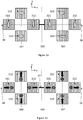
- Figure 2a illustrates a microelectromechanical gyroscope with a first proof mass quartet and a second proof mass quartet.
- the gyroscope comprises a first proof mass of the first proof mass quartet 211, a second proof mass of the first proof mass quartet 212, a third proof mass of the first proof mass quartet 213, and a fourth proof mass of the first proof mass quartet 214.
- the gyroscope also comprises a first proof mass of the second proof mass quartet 221, a second proof mass of the second proof mass quartet 222, a third proof mass of the second proof mass quartet 223, and a fourth proof mass of the second proof mass quartet 224.
- the first quartet center point is the point where the lateral axis 28 crosses the first transversal axis 291.
- the second quartet center point is the point where the lateral axis 28 crosses the second transversal axis 292.
- a third transversal axis 293 crosses the lateral axis between the second proof mass of the first proof mass quartet 212 and the first proof mass of the second proof mass quartet 221, as illustrated in Figure 2a .
- the first transversal axis 291 and the second transversal axis 292 are separated from each other on the lateral axis 28.
- the second proof mass 212 of the first proof mass quartet and the first proof mass 221 of the second proof mass quartet are positioned between the first and second quartet center points, on opposite sides of the third transversal axis 293.
- All proof masses may be suspended from a fixed support by flexible suspension springs (not illustrated in Figure 2a ) which allow oscillating movement.
- the gyroscope may also comprise capacitive or piezoelectric actuators (not illustrated in Figure 2a ) and a control unit which is configured to apply one or more drive voltage signals to the actuators. The control unit can thereby drive the primary oscillation of the proof masses.
- the Coriolis force sets at least some proof masses into secondary oscillation.
- the gyroscope further comprises coupling springs which synchronize motion of the proof masses so that the desired oscillation phases, which will be described in more detail below, are obtained.
- Some proof masses may not be directly connected to actuators. Their primary oscillation may instead be indirectly actuated by coupling springs which transmit the motion of one proof mass the proof mass which is not directly connected to actuators.
- the suspension springs includes central suspension arrangements formed near the quartet center points and peripheral suspension arrangements which support the weight of the proof masses closer to the periphery of the gyroscope. Any central and peripheral suspenders which flexibly allow the desired oscillation modes can be used, and their shape may depend on the shape of the proof masses. Exemplary suspension arrangements will be illustrated below.
- FIGS 2a and 2b illustrate a first oscillation mode example.
- the primary oscillation mode of each proof mass quartet is the first primary oscillation mode.
- each proof mass moves linearly in a radial direction in relation to the corresponding quartet center point.
- Each proof mass in the first proof mass quartet (211, 212, 213, 214) moves toward the first quartet center point when the corresponding proof mass in the second proof mass quartet (221, 222, 223 and 224, respectively) moves away from the second quartet center point, and vice versa,
- the first proof mass in each proof mass quartet moves toward the corresponding quartet center point when the second proof mass in the same proof mass quartet (212, 222) moves toward the same quartet center point, and the first proof mass (211, 221) moves away from the same quartet center point when the second proof mass (212, 222) in the same proof mass quartet moves away from the same quartet center point.
- each proof mass quartet (213, 223) moves toward the corresponding quartet center point when the fourth proof mass in the same proof mass quartet (214, 224) moves toward the same quartet center point, and the third proof mass (213, 223) moves away from the same quartet center point when the fourth proof mass (214, 224) in the same proof mass quartet moves away from the same quartet center point.
- the first and second proof masses (211+221, 221 +222) in each proof mass quartet move toward the corresponding quartet center point when the third and fourth proof masses in the same proof mass quartet (213+214, 223+224) move away from the same quartet center point, and vice versa.
- the primary oscillation of the proof mass 211 is in opposite phase to the oscillation of the proof mass 212 and the oscillation of the proof mass 213 is in the opposite phase to the oscillation of the proof mass 214.
- proof masses 211 and 212 move simultaneously away from the first quartet center point, and proof masses 213 and 212 move simultaneously toward the first quartet center point.
- opposite phase means that during the same oscillation half-cycle, the paired proof masses move in opposite directions along the same axis.
- the term "opposite phase” will also be used to indicate movement in opposite transversal directions (but along different transversal axes).
- the oscillation of proof masses 211 and 212 is in opposite phase to the oscillation of proof masses 213 and 214 in relation to the quartet center point, because the first and second proof masses 211 and 212 move toward the first quartet center point when the third and fourth proof masses move away from the same quartet center point, and vice versa.
- opposite phase in relation to the quartet center point means that during the same oscillation half-cycle the proof masses of one pair move towards the quartet center point while the proof masses of the other pair move away from the quartet center point. Similar conditions apply for the proof mass pairs 221+222 and 223+224 of the second quartet.
- each proof mass quartet comprises two proof mass pairs.
- a proof mass pair is formed by two proof masses on opposite sides of the quartet center point and the two proof masses of each pair oscillate in opposite phase along either the lateral or the second transversal axis.
- the two proof mass pairs 221+222 and 223+224 oscillate radially in opposite phase in relation to the second quartet center point.
- Opposite phase oscillation may also be called anti-phase oscillation in this disclosure.
- the primary oscillation mode of the two proof mass quartets is synchronized so that the phase of the primary oscillation of each proof mass in the first proof mass quartet is opposite to the phase of the primary oscillation of the corresponding proof mass in the second proof mass quartet.
- the first proof mass 211 of the first proof mass quartet moves away from the first quartet center point as the first proof mass 221 of the second proof mass quartet moves toward the second quartet center point.
- the movements of these two proof masses will be in the opposite directions.
- the same considerations apply to every pair of corresponding proof masses in the proof mass quartets: 212+222, 213+223 and 214+224.
- the quartet center points were to be taken as phase reference points also for each proof mass pair, it may be said in Figure 2a that the primary oscillation of the first proof mass in each proof mass quartet is radially cophasal with the primary oscillation of the second proof mass in the same proof mass quartet, and the phase of the primary oscillation of the third proof mass in each proof mass quartet is radially cophasal with the primary oscillation of the fourth proof mass in the same proof mass quartet.
- the phase of the primary oscillation of the first and second proof masses in each proof mass quartet in relation to the corresponding quartet center point could then also be described as radially anti-phasal to the primary oscillation of the third and fourth proof masses in the same proof mass quartet.
- this optional description of the illustrated phases will not be pursued further.
- Figure 2b illustrates the corresponding secondary oscillation modes.
- the Coriolis force will oscillate all proof masses tangentially.
- the first primary oscillation mode then induces a corresponding secondary oscillation mode where each proof mass within a proof mass pair oscillates in antiphase to the other proof mass of the pair.
- antiphase means that when one proof mass of a pair moves in a first lateral direction or in a first transversal direction, the other moves in an opposite lateral or transversal direction and both move in the same tangential direction (clockwise or counter-clockwise) in relation to their corresponding quartet center points.
- each proof mass quartet one pair of proof masses (for example 211+212) oscillates in antiphase to the other pair (213+214) in the quartet.
- Antiphase oscillation within a proof mass quartet means that if one pair moves tangentially clockwise during a half-cycle, the other moves counter-clockwise.
- first proof mass 211 of the first proof mass quartet and the first proof mass 221 of the second proof mass quartet move in opposite tangential directions (clockwise or counter-clockwise) in relation to their corresponding quartet center points, as illustrated in Figure 2b .
- the same situation again obtains for all the corresponding proof mass pairs in the two proof mass quartets: 212+222, 213+223 and 214+224.
- a connection element 27 which connects proof masses 212 and 221 may synchronize the z-axis secondary oscillation modes of the two proof mass quartets with each other.
- Capacitive or piezoelectric measurement transducers may be used to determine in-plane oscillation amplitudes in the z-axis secondary oscillation mode. Differential measurement of electrical signals from similar transducers attached to each proof mass can be used for cancelling errors and cross talk.
- rotational symmetry of proof mass-transducer geometry within a quartet is assumed (proof mass-transducers systems are copied, shifted and rotated) and the electrical signals from the transducers are designated by the symbols of the corresponding proof masses.
- signals that are in same phase can be summed: 211+212 and 213+214, and a difference of these two can be taken since they are in anti-phase: 211+212-213-214.
- the Coriolis force will oscillate the proof mass pairs (213+214 and 223+ 224) formed by the third and fourth proof masses in each proof mass quartet out of the device plane as illustrated in Figure 2b .
- These proof mass pairs are joined to each other by central suspension and coupling springs. These springs are not illustrated in Figure 2b for clarity but will be discussed below under the heading Suspension and Coupling Examples.
- proof mass pairs 213+214 and 223+224 will oscillate about the lateral axis 28 in anti-phase.
- the Coriolis force will oscillate the proof mass pairs (211+212 and 221 + 222) formed by the first and second proof masses in each proof mass quartet out of the device plane as illustrated in Figure 2b .
- these proof mass pairs are joined to each other by central suspension and coupling springs which are not illustrated in Figure 2b for clarity reasons.
- proof mass pairs 211+212 and 221+222 will oscillate about the respective transversal axes in anti-phase.
- the connection element 27 which connects proof masses 212 and 221 may also synchronize the x-axis secondary oscillation modes of the two proof mass quartets with each other.
- Capacitive or piezoelectric measurement transducers may be used to determine out-of-plane oscillation amplitudes in the x-axis and y-axis secondary oscillation modes. Differential measurement of electrical signals from similar transducers attached to each proof mass can be used for cancelling errors and cross talk.
- the electrical signals from the transducers are designated by the symbols of the corresponding proof masses. Within one quartet signals that are in opposite phase can be differenced: 211-212 and 221-222. Since the two quartets are in anti-phase, a difference of corresponding expressions can be taken leading finally to the total signal 211-212-221+222 for detecting the signal produced by y-axis rotation.
- Figure 2c illustrates tangential in-plane oscillation as a mixture of linear movement and rotation.
- Figure 2d illustrates out-of-plane oscillation as a mixture of linear movement and rotation.
- the suspension arrangement and couplings between proof masses which will be discussed in more detail below, will determine to which degree the rotational component will be present; in any case the linear movement will predominate. It may be advantageous to have a combination of linear and rotational movement that produces a circular planetary movement of the proof mass around the center of the quartet, as illustrated in Figure 2d where each proof mass pair 211+212 and 221+222 remains in the same plane (illustrated by axes 281 and 282, respectively) in out-of-plane oscillation.
- Figures 3a and 3b illustrate a second oscillation mode example.
- Reference numbers 311 - 314, 321 - 324, 38 and 391 - 393 correspond to reference numbers 211 - 214, 221 - 224, 28 and 291 - 293, respectively, in Figures 2a and 2b .
- each proof mass quartet is the second primary oscillation mode.
- each proof mass moves tangentially in relation to the corresponding quartet center point.
- Each proof mass in the first proof mass quartet (311, 312, 313 and 314) moves clockwise in relation to the first quartet center point when the corresponding proof mass in the second proof mass quartet (321, 322, 323 and 324, respectively) moves counter-clockwise in relation to the second quartet center point, and vice versa.
- the first proof mass (311, 321) in each proof mass quartet moves clockwise in relation to the corresponding quartet center point when the second proof mass in the same proof mass quartet (312, 322) moves clockwise in relation to the same quartet center point, and the first proof mass (311, 321) moves counter-clockwise in relation to the same quartet center point when the second proof mass (312, 322) counter-clockwise in relation to the same quartet center point.
- each proof mass quartet (313, 323) moves clockwise in relation to the corresponding quartet center point when the fourth proof mass in the same proof mass quartet (314, 324) moves clockwise in relation to the same quartet center point, and the third proof mass (313, 323) moves counter-clockwise in relation to the same quartet center point when the fourth proof mass (314, 324) moves counter-clockwise in relation the same quartet center point.
- each proof mass quartet (311+312, 321+322) move clockwise in relation to the corresponding quartet center point when the third and fourth proof masses in the same proof mass quartet (313+314, 323+324) move counter-clockwise in relation to the same quartet center point, and vice versa.
- phase of the primary oscillation of the first proof mass in each proof mass quartet (311, 321) in relation to the corresponding quartet center point is opposite to the phase of the primary oscillation of the second proof mass (312, 322) in the same proof mass quartet.
- opposite phase means that during a half-cycle of oscillation one proof mass moves in a first transversal direction whereas the other moves in the opposite transversal direction. Both masses move in the same tangential direction (clockwise or counter-clockwise) in relation to their corresponding quartet center points.
- the phase of the primary oscillation of the third proof mass in each proof mass quartet (313, 323) is opposite to the phase of the primary oscillation of the fourth proof mass (314, 324) in the same proof mass quartet.
- Opposite phase means that during a half-cycle of oscillation one proof mass moves in a first lateral direction whereas the other moves in the opposite lateral direction, and both move in the same tangential direction (clockwise or counter-clockwise) in relation to their corresponding quartet center points.
- the phase of the primary oscillation of the first and second proof masses in each proof mass quartet (311+312, 321+322) in relation to the corresponding quartet center point is anti-phase in relation to the phase of the primary oscillation of the third and fourth proof masses in the same proof mass quartet (313+314, 323+324, respectively) in relation to the same quartet center point.
- Anti-phase in relation to the quartet center point means that during a half-cycle of oscillation, the proof masses of one pair move tangentially in the opposite direction (clockwise or counter-clockwise) than the proof masses of the other pair.
- the primary oscillation mode of the two proof mass quartets is synchronized so that the phase of the primary oscillation of each proof mass in the first proof mass quartet is anti-phase in relation to the phase of the primary oscillation of the corresponding proof mass in the second proof mass quartet.
- the first proof mass 311 of the first proof mass quartet moves clockwise as the first proof mass 321 of the second proof mass quartet moves counter-clockwise.
- the movements of these two proof masses will be in the opposite directions.
- the same considerations apply to every pair of corresponding proof masses in the proof mass quartets: 312+322, 313+323 and 314+324.
- Figure 3b illustrates the corresponding secondary oscillation modes.
- the anti-phase primary oscillation mode induces a corresponding anti-phase secondary oscillation mode where the first proof mass 311 of the first proof mass quartet and the first proof mass 321 of the second proof mass quartet move in opposite radial directions in relation to their corresponding quartet center points, as illustrated in Figure 3b .
- the connection element 37 which connects proof masses 312 and 321 may synchronize the z-axis secondary oscillation modes of the two proof mass quartets with each other.
- Capacitive or piezoelectric measurement transducers may be used to determine in-plane oscillation amplitudes in the z-axis secondary oscillation mode. Differential measurement of electrical signals from similar transducers attached to each proof mass can be used for cancelling errors and cross talk.
- differential signal processing rotational symmetry of proof mass-transducer geometry within a quartet is assumed (proof mass-transducers systems are copied, shifted and rotated) and the electrical signals from the transducers are designated by the symbols of the corresponding proof masses.
- signals that are in same phase can be summed: 311+312 and 313+314, and a difference of these two can be taken since they are in anti-phase: 311+312-313-314.
- the Coriolis force will oscillate the proof mass pairs (311+312 and 321+322) formed by the first and second proof masses in each proof mass quartet out of the device plane as illustrated in Figure 3b .
- the central suspension and coupling springs which facilitate this oscillation will be illustrated below under the heading Suspension and Coupling Examples.
- proof mass pairs 311+312 and 321+322 oscillate about their respective transversal axes (391 or 392) in anti-phase.
- the connection element 37 which connects proof masses 312 and 321 may synchronize the x-axis secondary oscillation modes of the two proof mass quartets with each other.
- the Coriolis force will oscillate the proof mass pairs (313+314 and 323+ 324) formed by the third and fourth proof masses in each proof mass quartet out of the device plane, as illustrated in Figure 3b . Due to the anti-phase primary oscillation, this secondary oscillation about the lateral axis 38 also occurs in anti-phase.
- Capacitive or piezoelectric measurement transducers may be used to determine out-of-plane oscillation amplitudes in the x-axis and y-axis secondary oscillation modes. Differential measurement of electrical signals from similar transducers attached to each proof mass can be used for cancelling errors and cross talk.
- the electrical signals from the transducers are designated by the symbols of the corresponding proof masses. Within one quartet signals that are in opposite phase can be differenced: 311-312 and 321-322. Since the two quartets are in anti-phase a difference of corresponding expressions can be taken leading finally to the total signal 311-312-321+322 for detecting the signal produced by x-axis rotation.
- the primary and secondary oscillation modes illustrated in Figures 2a - 2b and 3a - 3b make the gyroscope robust against external disturbances and immune to energy flow out of the oscillation mode because the momentum of each moving proof mass one side of the gyroscope is balanced by the opposite momentum of another proof mass on the other side of the gyroscope, and because for the in-plane modes the momentums are balanced already within one quartet of proof masses by the momentum of another proof mass within the quartet.
- Anti-phase oscillation of the two proof mass pairs (e.g. 211+212 and 213+214) within each quartet also allows advantageous central suspensions to be used, since the volume change produced by this kind of motion in a closed suspension structure is zero in the area close to the center of the quartet.
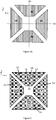
- Figure 4a illustrates a geometry where square-shaped proof masses 41 - 44 have been tilted 45 degrees with respect to the lateral axis 48 and transversal axis 49. This allows a denser grouping close to the quartet center point.
- Figure 4b illustrates another geometry which consumes less surface area.
- the proof masses 41 - 44 are shaped as right-angled triangles. More generally, the shape of each proof mass may be an isosceles triangle, and the tip each isosceles triangle may point toward the quartet center point as in Figure 4b .
- Figure 4c illustrates a geometry where the proof masses 41 - 44 are shaped as truncated isosceles (in this case truncated right-angled) triangles where the tip of the triangle has been truncated. This shape can be beneficial if the suspension and coupling arrangements involve some springs which must be placed near the quartet center point.
- suspension refers in this disclosure to an arrangement of one or more flexible springs, which may also be called suspenders, and which extend from a fixed support to a partly mobile element such as a proof mass.
- the place where the suspender is attached to the fixed support may be called an anchor point.
- the flexibility of the suspenders renders the proof mass partly mobile, so that they can be set into their primary oscillation mode by drive transducers at or close to the resonant frequency determined by the inertia of the proof mass and compliance of the suspension.
- Coupled refers in this disclosure to an arrangement of one or more flexible springs, which may be called coupling springs or synchronization springs, which stabilize the system of oscillating proof masses towards the desired synchronization. Coupling arrangements may also include rigid elements. The coupling function may also be embedded in the suspension and vice versa, the coupling elements may be part of the suspension that determines the resonant frequency.
- coupling arrangement will in this disclosure cover both suspensions and couplings.
- Suspension arrangements should flexibly accommodate, and preferably also synchronize, all the desired primary and secondary oscillation modes of the first and second proof mass quartets. Suspension arrangements should also preferably resist undesired oscillation modes. For every desired anti-phase oscillation mode discussed in this disclosure, there exists a corresponding cophasal oscillation mode which would disturb the measurement if its amplitude and frequency correspond to those of the desired anti-phase oscillation mode. The suspension arrangements should therefore preferably suppress those cophasal oscillation modes. Saying that an undesired movement or oscillation is resisted, prevented or suppressed signifies in this disclosure that the spring constant of the suspension arrangement for the undesired movement or oscillation (e.g.
- cophasal is substantially higher than the spring constant of the desired movement or oscillation (e.g. anti-phase) and thus the resonant frequency of the undesired oscillation mode is considerably higher (e.g. above 50 kHz for automotive applications) than that of the desired mode (typically in the 10...30 kHz range).
- both proof mass quartets may be suspended and internally coupled with the same internal suspension arrangement. Both proof mass quartets may in some cases also be suspended and internally coupled with different internal suspension arrangements but achieving perfect symmetry for differential cancellation of errors and synchronization of the oscillations may then be difficult.
- FIG. 5 illustrates an example of a central suspension arrangement which is applicable in all oscillation mode examples presented above.
- Each proof mass comprises an opening and an anchor point 55 is arranged inside each opening.
- the suspension arrangement further comprises two inner meander springs 56 which extend from the anchor point to a gimbal frame 57 on opposite sides of the anchor point.
- the gimbal frame 57 surrounds the anchor point 55 and the inner meander springs 56.
- Two outer meander springs 58 extend from the gimbal frame to the surrounding proof mass on opposite sides of the gimbal frame 57.
- the outer meander springs 58 are orthogonal to the inner meander springs 56.
- the inner meander springs extend in a transversal direction within the first and second proof masses 51 and 52, while the inner meander springs extend in a lateral direction in third and fourth proof masses 53 and 54.
- the outer meander springs extend in a lateral direction within the first and second proof masses 51 and 52, while the outer meander springs extend in a transversal direction in third and fourth proof masses 53 and 54.
- the inner and outer meander springs 56 and 58 allow each proof mass to move in both the lateral and the transversal direction.
- the folded sections in the inner and outer meander springs 56 and 58 should be sufficiently long to allow also out-of-plane translation and rotation of the proof mass.
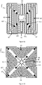
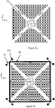
- Figure 6a illustrates an example of a central and peripheral suspension arrangement which is applicable in all oscillation mode examples presented above.
- the suspension arrangement comprises four inner anchor points 651 and four outer anchor points 652.
- One inner and one outer anchor point is placed between each pair of adjacent proof masses.
- the inner and outer anchor points are located on axes which are tilted 45 degrees with respect to the lateral axis and the transversal axis, which have been omitted from the figure for clarity reasons.
- One inner suspension spring 66 extends from each inner anchor point 651, toward the central tip of each of the adjacent proof masses. In other words, two inner suspension springs extend away from the inner anchor point towards the center, along the sides of the respective proof masses. Since each proof mass (for example 64 in Figure 6a ) is flanked by two inner anchor points 651, two inner suspension springs 66 meet each other at a meeting point 661, where a short connecting spring attaches them to the tip of the proof mass.
- one outer suspension spring 67 extends from each outer anchor point 652 to the outer side of each of the adjacent proof masses.
- two outer suspension springs extend away from the outer anchor point, along the sides of the respective proof masses. These outer springs may, for example, reach around the corner of the proof mass as illustrated in Figure 6a . Since each proof mass (for example 64 in Figure 6a ) is flanked by two outer anchor points 652, two outer suspension springs 67 go around the two base corners of the proof mass and are attached to the outer edge of the proof mass 64.
- inner and outer suspension springs 66 and 67 that have both in-plane and out-of-plane flexibility allows each proof mass to move in lateral, transversal and vertical directions as well as to rotate in both in-plane and out-of-plane directions.
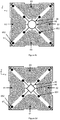
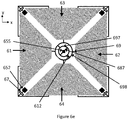
- Figures 6b , 6c 6d and 6e illustrate alternatives to the central and peripheral suspension arrangement illustrated in Figure 6a .
- the inner springs branch out to a four-pointed star-shaped coupling pattern at the center and connect to it at the inner edges of the star.
- Proof masses are connected to the outer edges of the star by coupling beams 68 that have in-plane flexibility to allow tangential in-plane movement of the proof masses as well as torsional flexibility to allow out-of-plane rotation of the star and a pair of proof masses.
- the beams 68 are rigid so that a pair of proof masses can essentially rotate around the center of the quartet as illustrated in Figures 2d and 2e .
- the outer springs branch out towards the outer sides of the two adjacent proof masses at each corner of the proof mass quartet.
- the star-shaped pattern may alternatively be shaped as an octagon or a ring ( Figure 6c ), or as a diamond ( Figure 6d ). Some or all of the edges of the star-shaped, octagon-shaped or diamond-shaped pattern may be rounded. Any intermediate form between these patterns is also applicable.
- Figure 6e illustrates another alternative.
- the central suspension arrangement comprises a central anchor point 655 located at the quartet center point.
- the central suspension arrangement also comprises a gimbal structure illustrated in Figure 6e .
- Two first torsion bars 687 extend diagonally from the central anchor point to an inner gimbal frame 697, and two second torsion bars 688, perpendicular to the first bars 687, extend from the inner gimbal frame 697 to the outer gimbal frame 698.
- the inner gimbal frame 697 is circular
- the outer gimbal frame 698 is circular
- each proof mass in the corresponding proof mass quartet is attached to the outer gimbal frame 698 with an attachment part 69.
- the outer gimbal frame 698 can assume an elliptical shape along either of the transversal and lateral axes to accommodate and synchronize the anti-phase in-plane oscillation of the two proof mass pairs. It is possible have more than two gimbal frames or other similar bodies with central anchoring, and an outer synchronization body that will perform the same function as the one presented in Figure 6e . The direction of the torsion bars 687 and 697 may then be different from Figure 6e .
- the central suspension arrangement can be implemented with any symmetrical closed pattern that will easily contract on one axis with a matching forced expansion on an orthogonal axis so that the net area change of the pattern is essentially zero and there is no linear movement along the diagonal axes rotated 45 degrees from x- and y-axes and going through the center of the quartet.
- the suspension arrangement illustrated in Figure 6b , 6c , 6d and 6e can be used for the oscillation modes illustrated in Figures 2a - 2b and 3a - 3b .
- the central suspension will then also synchronize the radial movement of the four proof masses ( Figures 2a and 3b ), while the peripheral suspension will synchronize their tangential movement ( Figures 2b and 3a ).
- the central suspension arrangement facilitates mutual out-of-plane oscillation of the proof mass pair 61+62 in relation to the transversal axis, and mutual out-of-plane oscillation of the proof mass pair 63+64 in relation to the lateral axis in such a manner that one proof mass pair is not put in motion if the other one oscillates.
- the central suspension arrangement will prevent all other radial oscillation modes besides the desired anti-phase radial oscillation of the two orthogonal proof mass pairs 61+62 and 63+64.
- Figure 7a illustrates additional synchronization springs 77 which may be implemented between adjacent proof masses together with any of the preceding suspension arrangements or with any other suspension arrangements that may be used.
- the suspension arrangements illustrated in Figures 6a, 6b , 6c, 6d and 6e may synchronize the oscillation modes sufficiently well even without such additional synchronization springs.
- FIG. 7b illustrates yet another possible arrangement for synchronizing the tangential in-plane motion of the proof mass quartet.
- Each proof mass is suspended with suspenders 78, which may have the required in-plane and out-of-plane flexibility to allow proper resonant frequencies in these directions.
- the suspenders 78 are connected to diagonal supporting beams 79, which are connected at least at one end to anchor points 710.
- the proof masses are connected to the mid-point of the suspenders 78.
- the beams 79 have in-plane flexibility but are rigid for out-of-plane bending.
- the supporting beams 79 will bend and allow motion when two neighboring proof masses move in the opposite tangential direction, one clockwise and the other counter-clockwise, but they will resist motion when the proof masses try to move in the same tangential direction.
- the suspenders 78 and the beam 79 synchronize the anti-phase oscillation of two neighboring proof masses and resist the co-phasal oscillation of the same two neighboring proof masses. If similar structures are placed on each corner of the quartet as in Figure 7b , the in-plane tangential oscillation of all the four proof masses is synchronized to the desired anti-phase mode for each proof mass within a pair of opposite proof masses and for each proof mass pair within the quartet, and all the corresponding cophasal oscillations are prevented.
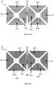
- Figure 8a illustrates one example of a synchronization arrangement between the first proof mass quartet and the second proof mass quartet.
- Reference numbers 811 - 814 and 821 - 824 correspond to reference numbers 211 - 214 and 221 - 224, respectively, in Figure 2a .
- the second proof mass 812 in the first proof mass quartet and the first proof mass 821 in the second proof mass quartet are connected to each other with a rigid bar 83.
- the rigid bar may correspond to connection elements 27 and 37 in figures 2b and 3b , respectively.
- the rigid bar 83 can be used to synchronize all of the oscillation modes illustrated in Figures 2a - 3b , since the masses which correspond to 812 and 821 in these figures always move in the same direction. Assuming that the internal synchronization of each proof mass quartet works as desired, the rigid bar will synchronize the entire gyroscope except the out-of-plane movement of proof mass pairs 813+814 and 823+824.
- out-of-plane oscillation modes should in this case be linear, not rotational, since rotational oscillation would mean that proof masses 812 and 821 rotate together with their opposing proof mass pair about their respective transversal axes (the first and second transversal axes of the gyroscope).
- the rigid bar 83 would not allow such rotation, but it does allow simultaneous out-of-plane linear movement of proof masses 812 and 821.
- Figure 8b illustrates an alternative embodiment where a spring 84 has been attached between proof masses 812 and 821.
- This spring may correspond to connection elements 27 and 37 in figures 2b and 3b , respectively.
- the spring transfers motion in lateral, transversal and out-of-plane directions from proof mass 812 to 821 and vice versa, so that the primary oscillation mode, the z-axis secondary oscillation mode and one the out-of-plane secondary oscillation modes, namely that of the proof mass pairs 811+812 and 821+822, are effectively synchronized between the first and second proof mass quartets while the movement of proof mass pairs 813+814 and 823+824 is not synchronized.
- the spring 84 may be relatively rigid for linear movement in the transversal direction, so that the transversal anti-phase movement between 812 and 821 is prevented.
- the spring 84 may be flexible for rotation about the z-axis allowing an in-plane tilt angle between the proof masses 812 and 821 and thus the desired anti-phase rotation about each proof masses quartet center.
- the spring may be also flexible for rotation about the third transversal axis 893, so that it allows out-of-plane rotational movement of the proof masses by allowing a tilt angle between them but doesn't allow anti-phase out-of-plane movement between 812 and 821.
- Figures 8c and 8d illustrate a possible structure for the spring 84 as a cross section and as an in-plane view, correspondingly.
- Spring 84 may contain at least one bar 85 in the direction of the transversal axis 893, which has in-plane flexibility and torsional flexibility, but which is rigid for out-of-plane bending.
- One of the proof masses 812 or 821 is attached to the mid-point of the bar 85 and the other proof mass to the ends of the bar.
- the spring 84 is symmetrical containing two bars 85 attached to each other at the ends and to the proof masses at the mid-points. Other spring constructions may also be used.
- the second proof mass in the first proof mass quartet is mechanically coupled to the first proof mass in the second proof mass quartet by at least one coupling spring 84 aligned on the third transversal axis 893 in the device plane.
- the at least one coupling spring 84 may allow the second proof mass 812 in the first proof mass quartet and the first proof mass 821 in the second proof mass quartet to simultaneously rotate in opposite out-of-plane directions about corresponding transversal axes.
- These corresponding transversal axes may be the first and second transversal axes, so that 812 rotates about the first transversal axis while 821 rotates about the second transversal axis, or they may be transversal axes which pass through the proof masses 812 and 821, respectively.
- the second proof mass 812 in the first proof mass quartet and the first proof mass 821 in the second proof mass quartet may also rotate in opposite in-plane directions about corresponding vertical axes.
- These corresponding vertical axes may be the vertical axes which cross the first and second quartet center points, so that 812 rotates about the vertical axis which crosses the first quartet center point while 821 rotates about the vertical axis which crosses the second quartet center point, or they may be vertical axes which pass through the proof masses 812 and 821, respectively.
- the at least one coupling spring 84 allows simultaneous cophasal linear translation of the second proof mass 812 in the first proof mass quartet and the first proof mass 821 in the second proof mass quartet in a direction parallel to the lateral axis, parallel to any transversal axis, or parallel to any vertical axis.
- the at least one coupling spring 84 may further resist the simultaneous rotation of the second proof mass 812 in the first proof mass quartet and the first proof mass 821 in the second proof mass quartet in the same out-of-plane direction about corresponding transversal axes.
- These corresponding transversal axes may be the first and second transversal axes, so that 812 rotates about the first transversal axis while 821 rotates about the second transversal axis, or they may be transversal axes which pass through the proof masses 812 and 821, respectively.
- the at least one coupling spring 84 may further resist the simultaneous rotation of the second proof mass 812 in the first proof mass quartet and the first proof mass 821 in the second proof mass quartet to the same in-plane direction about corresponding vertical axes.
- These corresponding vertical axes may be the vertical axes which cross the first and second quartet center points, so that 812 rotates about the vertical axis which crosses the first quartet center point while 821 rotates about the vertical axis which crosses the second quartet center point, or they may be vertical axes which pass through the proof masses 812 and 821, respectively.
- the at least one coupling spring 84 may further resist simultaneous anti-phase linear translation of the second proof mass 812 in the first proof mass quartet and the first proof mass 821 in the second proof mass quartet in opposite directions parallel to any transversal axis, or parallel to any vertical axis.
- the at least one coupling spring 84 may also resist simultaneous rotation of the second proof mass in the first proof mass quartet and the first proof mass in the second proof mass quartet in opposite directions about the lateral axis.
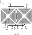
- FIG. 9 Other proof masses in the proof mass quartets can be connected with peripheral synchronization structures, for example of the kind illustrated in Figure 9 .
- Reference numbers 911 - 914 and 921 - 924 correspond to reference numbers 211 - 214 and 221 - 224, respectively, in Figure 2a .
- the synchronization structure comprises an upper part above the lateral axis and a separate lower part below the lateral axis. Only the lower part will be described in detail. The same considerations apply to the upper part as well.
- the lower synchronization structure illustrated in Figure 9 comprises an anchor point 951 aligned in the third transversal axis.
- the anchor point 951 may, but does not have to, be located between the fourth proof mass 914 of the first quartet and the and fourth proof mass 924 of the second quartet. It may also be located on the other side of the synchronization structure.
- the structure further comprises a relatively rigid lateral seesaw 971 which is connected to the anchor point 951 and to proof masses 914 and 924 with transversal torsion/ flexure bars 961 - 962. These torsion/ flexure bars are flexible for in-plane bending and for twisting, but they are rigid for out-of-plane bending.
- torsion/ flexure bars allow the lateral seesaw 971 to rotate about the third transversal axis, and thereby to synchronize the out-of-plane anti-phase secondary oscillation modes of the fourth proof masses 914 and 924 illustrated in Figures 2b , 3b .
- the upper synchronization structure can correspondingly synchronize the anti-phase out-of-plane oscillation of the third proof masses 913 and 923.
- Torsion/ flexure bars 961 - 962 may also resist the linear movement of the lateral seesaw 971 along the vertical axis, and thereby prevent the out-of-plane cophasal oscillation mode of the fourth proof masses 914 and 924.
- the upper synchronization structure can correspondingly resist the cophasal out-of-plane oscillation of the third proof masses 913 and 923.
- Torsion/ flexure bars 961 - 962 may also allow the lateral seesaw 971 to rotate about a vertical axis, and thereby to synchronize the radial in-plane anti-phase oscillation mode of the fourth proof masses 914 and 924 illustrated in Figures 2a , 3b .
- the upper synchronization structure can correspondingly synchronize the in-plane anti-phase oscillation of the third proof masses 913 and 923.
- Torsion/ flexure bars 961 - 962 also may resist the linear movement of the lateral seesaw 971 along a transversal axis, and thereby prevent the radial in-plane cophasal oscillation mode of the fourth proof masses 914 and 924.
- the upper synchronization structure can correspondingly resist the in-plane cophasal oscillation of the third proof masses 913 and 923.
- Torsion/ flexure bars 962 are flexible for in-plane bending and may therefore allow the in-plane tangential anti-phase oscillation of the proof masses 914 and 924 illustrated in Figures 2b , 2c and 3a but not synchronize it nor prevent the corresponding cophasal oscillation.
- the upper synchronization structure can correspondingly allow the in-plane tangential anti-phase oscillation of the third proof masses 913 and 923 but not synchronize it nor prevent the corresponding cophasal oscillation.
- Out-of-plane oscillation may also be synchronized by other means not illustrated in this disclosure.
- Capacitive or piezoelectric drive transducers may be incorporated in the gyroscope to facilitate primary oscillation.
- the gyroscope may comprise a control unit which is configured to apply a drive voltage signal to the drive transducers.
- the frequency of the drive voltage signals may in part determine the frequency and amplitude of the primary oscillation mode, and the amplitude of the drive voltage signals may in part determine the amplitude of the primary oscillation mode.
- the frequency of the drive voltage should be close to the resonant frequency of the primary mechanical oscillator determined by the inertia of the proof masses and compliance of the suspenders, but an exact match is not mandatory.
- the same drive voltage signal may be applied to multiple drive transducers.
- first drive voltage signal may be applied to drive transducers in the first proof mass quartet
- second drive voltage signal may be applied to drive transducers in the second proof mass quartet.
- Different drive voltage signals may also be applied to masses in the same proof mass quartet.
- Many other drive signal alternatives are also possible for driving the primary oscillation.
- Capacitive or piezoelectric sense transducers may be incorporated in the gyroscope to measure secondary oscillation induced by the Coriolis force.
- the control unit may be configured to measure a sense voltage signal or sense current signal from the sense transducers.
- the amplitude of the sense voltage or sense current signal may be used to calculate the corresponding angular rotation rate.
- the sense voltage or sense current signal may be generated as a sum or difference or combination thereof of several sense signal components retrieved from separate sense transducers or as a general weighted linear combination of several sense signals retrieved from separate sense transducers.
- FIG 10a illustrates a proof mass quartet with four capacitive outer drive transducers 1011.
- Each transducer comprises a set of rotor finger electrodes on the partly mobile proof masses and a set of stator finger electrodes on an adjacent fixed structure (the fixed structure is not illustrated).
- the capacitive drive transducers may be used to drive the first primary oscillation mode.
- Figure 10b illustrates a proof mass quartet with four capacitive outer drive transducers 1012 and four capacitive inner drive transducers 1022.
- the inner drive transducers are located in an opening formed within the respective proof mass.
- the capacitive drive transducers may be used to drive the second primary oscillation mode.
- Figure 11a illustrates a proof mass quartet with four capacitive outer sense transducers 1112 and four capacitive inner sense transducers 1122.
- sense transducers are equipped with fingers oriented in the lateral direction, and others with fingers oriented in the transversal direction, both radial and tangential in-plane movement can be detected.
- Figure 11b illustrates a proof mass quartet with first proof mass 111, second proof mass 112, and capacitive sense transducers for detecting out-of-plane oscillation.
- the sense transducers comprise planar electrodes above and/or below the proof masses. In the upper figure, the location of the planar electrodes is illustrated with dashed lines.
- the area of the planar electrodes may be contained within the area of the proof masses, as illustrated in Figure 11b , or the area of the proof masses may be contained within the area of the proof masses. The overlap between these areas should preferably not change when the masses undergo in-plane oscillation, since this might add undesired modulation to the out-of-plane sense signal.
- the lower figure illustrates planar electrodes 1111 and 1112 on the surface of a supporting substrate 119.
- Opposing planar electrodes may be formed on the proof masses 111 and 112 so that a capacitive parallel-plate measurement can be performed.
- the proof masses 111 and 112 may themselves be used as the second planar electrodes of the capacitive sense transducers.
Landscapes
- Physics & Mathematics (AREA)
- Engineering & Computer Science (AREA)
- General Physics & Mathematics (AREA)
- Radar, Positioning & Navigation (AREA)
- Remote Sensing (AREA)
- Gyroscopes (AREA)
Claims (2)
- Gyroscope microélectromécanique dans lequel le gyroscope comprend un premier quatuor de masses d'épreuve (211 - 214, 311 - 314, 811 - 814) et un deuxième quatuor de masses d'épreuve (221 - 224, 321 - 324, 821 - 824) dans un plan de composant avec un premier centre de quatuor correspondant et un deuxième centre de quatuor correspondant qui se situent sur un axe latéral (28, 38),
dans lequel les quatre masses d'épreuve (211 - 214, 311 - 314, 811 - 814) qui constituent le premier quatuor de masses d'épreuve (211 - 214, 311 - 314, 811 - 814) sont disposées, en leur position de repos, de manière symétrique autour du premier centre de quatuor où l'axe latéral (28, 38) croise orthogonalement un premier axe transversal (291, 391, 891) dans le plan de composant, et les quatre masses d'épreuve (221 - 224, 321 - 324, 821 - 824) qui constituent le deuxième quatuor de masses d'épreuve (221 - 224, 321 - 324, 821 - 824) sont disposées, en leur position de repos, de manière symétrique autour du deuxième centre de quatuor où l'axe latéral (28, 38) croise orthogonalement un deuxième axe transversal (292, 392, 892) dans le plan de composant, et dans lequel
de premières (211, 221, 311, 321, 811, 821) et deuxièmes (212, 222, 312, 322, 812, 822) masses d'épreuve dans chaque quatuor de masses d'épreuve sont alignées sur l'axe latéral (28, 38) en leur position de repos, et de troisièmes (213, 313, 813) et quatrièmes (214, 314, 814) masses d'épreuve dans le premier quatuor de masses d'épreuve sont alignées sur le premier axe transversal (291, 391, 891) en leur position de repos, et de troisièmes (223, 323, 823) et quatrièmes (224, 324, 824) masses d'épreuve dans le deuxième quatuor de masses d'épreuve sont alignées sur le deuxième axe transversal (292, 392, 892) en leur position de repos, et les positions de repos des premières (211, 221, 311, 321, 811, 821), deuxièmes (212, 222, 312, 322, 812, 822), troisièmes (213, 223, 313, 323, 813, 823) et quatrièmes (214, 224, 314, 324, 814, 824) masses d'épreuve dans les deux quatuors sont les mêmes par rapport au centre de quatuor correspondant,
et le gyroscope comprend au moins un ressort de couplage (84) aligné sur un troisième axe transversal (293, 393, 893) dans le plan de composant, et la deuxième masse d'épreuve (212, 312, 812) dans le premier quatuor de masses d'épreuve est adjacente et mécaniquement couplée à la première masse d'épreuve (221, 321, 821) dans le deuxième quatuor de masses d'épreuve avec ledit au moins un ressort de couplage (84), et ledit au moins un ressort de couplage (84) autorise une translation linéaire simultanée en phase de la deuxième masse d'épreuve (212, 312, 812) dans le premier quatuor de masses d'épreuve et de la première masse d'épreuve (221, 321, 821) dans le deuxième quatuor de masses d'épreuve dans une direction parallèle à l'axe latéral (28, 38), parallèle à un axe transversal, ou parallèle à un axe vertical,
et le gyroscope comprend également un ou plusieurs transducteurs d'entraînement pour mettre les premier et deuxième quatuors de masses d'épreuve en un mouvement oscillatoire primaire, et un ou plusieurs transducteurs de détection pour détecter un mouvement oscillatoire secondaire des premier et deuxième quatuors de masses d'épreuve qui est induit par la force de Coriolis si le gyroscope subit une rotation angulaire,
et le gyroscope comprend également un agencement de suspension pour suspendre les premier et deuxième quatuors de masses d'épreuve à une structure d'appui fixée, ladite structure de suspension étant configurée pour absorber le mouvement oscillatoire primaire et secondaire des premier et deuxième quartes de masses d'épreuve,
et l'agencement de suspension comprend, autour de chaque centre de quatuor, un agencement de suspension central qui comprend une structure fermée symétrique dans le plan de composant qui est ancrée à un ou plusieurs points d'ancrage intérieurs et couplée à chaque masse dans le quatuor de masses d'épreuve correspondant de telle façon que la structure fermée symétrique se contracte facilement sur l'axe latéral lors d'une expansion forcée correspondante sur l'axe transversal, et vice versa,
et les transducteurs d'entraînement sont configurés pour mettre en oscillation primaire toutes les quatre masses d'épreuve (211 - 214, 311 - 314, 221 - 224, 321 - 324, 811 - 814, 821 - 824) dans chaque quatuor de masses d'épreuve dans le plan de composant, soit dans un premier mode d'oscillation primaire, soit dans un deuxième mode d'oscillation primaire,
ledit premier mode d'oscillation primaire comprenant un mouvement où chaque masse d'épreuve (211 - 214, 311 - 314, 221 - 224, 321 - 324, 811 - 814, 821 - 824) oscille dans un sens radial par rapport au centre de quatuor correspondant, et ledit deuxième mode d'oscillation primaire comprenant un mouvement où chaque masse d'épreuve (211 - 214, 311 - 314, 221 - 224, 321 - 324, 811 - 814, 821 - 824) oscille dans un sens tangentiel par rapport au centre de quatuor correspondant,
et l'oscillation primaire dans le premier mode d'oscillation primaire est synchronisée à tel point que :- chaque masse d'épreuve dans le premier quatuor de masses d'épreuve (211 - 214, 311 - 314, 811 - 814) se rapproche du premier centre de quatuor lorsque la masse d'épreuve correspondante dans le deuxième quatuor de masses d'épreuve (221 - 224, 321 - 324, 821 - 824) s'éloigne du deuxième centre de quatuor, et vice versa,- la première masse d'épreuve (211, 221, 311, 321, 811, 821) dans chaque quatuor de masses d'épreuve se rapproche du centre de quatuor correspondant lorsque la deuxième masse d'épreuve (212, 222, 312, 322, 812, 822) dans le même quatuor de masses d'épreuve se rapproche du même centre de quatuor, et s'éloigne du même centre de quatuor lorsque la deuxième masse d'épreuve (212, 222, 312, 322, 812, 822) dans le même quatuor de masses d'épreuve s'éloigne du même centre de quatuor,- la troisième masse d'épreuve (213, 223, 313, 323, 813, 823) dans chaque quatuor de masses d'épreuve se rapproche du centre de quatuor correspondant lorsque la quatrième masse d'épreuve (214, 224, 314, 324, 814, 824) dans le même quatuor de masses d'épreuve se rapproche du même centre de quatuor, et s'éloigne du même centre de quatuor lorsque la quatrième masse d'épreuve (214, 224, 314, 324, 814, 824) dans le même quatuor de masses d'épreuve s'éloigne du même centre de quatuor, et- les premières (211, 221, 311, 321, 811, 821) et deuxièmes (212, 222, 312, 322, 821, 822) masses d'épreuve dans chaque quatuor de masses d'épreuve se rapprochent du centre de quatuor correspondant lorsque les troisièmes (213, 223, 313, 323, 813, 823) et quatrièmes (214, 224, 314, 324, 814, 824) masses d'épreuve dans le même quatuor de masses d'épreuve s'éloignent du même centre de quatuor, et vice versa,et l'oscillation primaire dans le deuxième mode d'oscillation primaire est synchronisée à tel point que :- chaque masse d'épreuve (211 - 214, 311 - 314, 811 - 814) dans le premier quatuor de masses d'épreuve se déplace dans le sens horaire par rapport au premier centre de quatuor lorsque la masse d'épreuve correspondante (221 - 224, 321 - 324, 821 - 824) dans le deuxième quatuor de masses d'épreuve se déplace dans le sens anti-horaire par rapport au deuxième centre de quatuor, et vice versa,- la première masse d'épreuve (211, 221, 311, 321, 811, 821) dans chaque quatuor de masses d'épreuve se déplace dans le sens horaire par rapport au centre de quatuor correspondant lorsque la deuxième masse d'épreuve (212, 222, 312, 322, 812, 822) dans le même quatuor de masses d'épreuve se déplace dans le sens horaire par rapport au même centre de quatuor, et dans le sens anti-horaire par rapport au même centre de quatuor lorsque la deuxième masse d'épreuve (212, 222, 312, 322, 812, 822) dans le même quatuor de masses d'épreuve se déplace dans le sens anti-horaire par rapport au même centre de quatuor,- la troisième masse d'épreuve (213, 223, 313, 323, 813, 823) dans chaque quatuor de masses d'épreuve se déplace dans le sens horaire par rapport au centre de quatuor correspondant lorsque la quatrième masse d'épreuve (214, 224, 314, 324, 814, 824) dans le même quatuor de masses d'épreuve se déplace dans le sens horaire par rapport au même centre de quatuor, et dans le sens anti-horaire par rapport au même centre de quatuor lorsque la quatrième masse d'épreuve (214, 224, 314, 324, 814, 824) dans le même quatuor de masses d'épreuve se déplace dans le sens anti-horaire par rapport au même centre de quatuor, et- les premières (211, 221, 311, 321, 811, 821) et deuxièmes (212, 222, 312, 322, 812, 822) masses d'épreuve dans chaque quatuor de masses d'épreuve se déplacent dans le sens horaire par rapport au centre de quatuor correspondant lorsque les troisièmes (213, 223, 313, 323, 813, 823) et quatrièmes (214, 224, 314, 324, 814, 824) masses d'épreuve dans le même quatuor de masses d'épreuve se déplacent dans le sens anti-horaire par rapport au même centre de quatuor, et vice versa,et les modes d'oscillation secondaires des premier et deuxièmes quatuors de masses d'épreuve comprennent un mode secondaire d'axe z, un mode secondaire d'axe x et/ou un mode secondaire d'axe y à tel point que, si le mode d'oscillation primaire de chaque quatuor de masses d'épreuve est le premier mode d'oscillation primaire, alors- en réponse à une rotation du gyroscope autour de l'axe z, le mode secondaire d'axe z comprend un mouvement dans lequel chaque masse d'épreuve (211 - 214, 221 - 224, 311 - 314, 321 - 324, 811 - 814, 821 - 824) dans chaque quatuor de masses d'épreuve oscille tangentiellement par rapport au centre de quatuor correspondant,- en réponse à une rotation du gyroscope autour d'un axe x, qui est parallèle à l'axe latéral, le mode secondaire d'axe x comprend un mouvement dans lequel chaque paire de masses d'épreuve (213+214, 223+224, 313+314, 323+324, 813+814, 823+824) constituée par les troisièmes et quatrièmes masses d'épreuve oscille hors du plan de composant,- en réponse à une rotation du gyroscope autour de l'axe y, qui est parallèle aux premier et deuxième axes transversaux, le mode secondaire d'axe y comprend un mouvement dans lequel chaque paire de masses d'épreuve (211+212, 221+222, 311+312, 321+322, 811+812, 821+822) constituée par les premières et deuxièmes masses d'épreuve oscille hors du plan de composant,et à tel point que, si le mode d'oscillation primaire de chaque quatuor de masses d'épreuve est le deuxième mode d'oscillation primaire, alors- en réponse à une rotation du gyroscope autour de l'axe z, le mode secondaire d'axe z comprend un mouvement dans lequel chaque masse épreuve (211 - 214, 221 - 224, 311 - 314, 321 - 324, 811 - 814, 821 - 824) oscille radialement par rapport au centre de quatuor correspondant,- en réponse à une rotation du gyroscope autour d'un axe x, qui est parallèle à l'axe latéral, le mode secondaire d'axe x comprend un mouvement dans lequel chaque paire de masses d'épreuve (211+212, 221+222, 311+312, 321+322, 811+812, 821+822) constituée par les premières et deuxièmes masses d'épreuve oscille hors du plan de composant,- en réponse à une rotation du gyroscope autour de l'axe y, qui est parallèle aux premier et deuxième axes transversaux, le mode secondaire d'axe y comprend un mouvement dans lequel chaque paire de masses d'épreuve (213+214, 223+224, 313+314, 323+324, 813+814, 823+824) constituée par les troisièmes et quatrièmes masses d'épreuve oscille hors du plan de composant. - Gyroscope microélectromécanique selon la revendication 1, caractérisé en ce que ledit au moins un ressort de couplage (84) permet également :- à la deuxième masse d'épreuve (812) dans le premier quatuor de masses d'épreuve et à la première masse d'épreuve (821) dans le deuxième quatuor de masses d'épreuve de tourner simultanément dans des sens opposés hors du plan autour d'axes transversaux correspondants,- à la deuxième masse d'épreuve (812) dans le premier quatuor de masses d'épreuve et à la première masse d'épreuve (821) dans le deuxième quatuor de masses d'épreuve de tourner simultanément dans des sens opposés en plan autour d'axes verticaux correspondants,
Applications Claiming Priority (1)
| Application Number | Priority Date | Filing Date | Title |
|---|---|---|---|
| FI20186114 | 2018-12-19 |
Publications (2)
| Publication Number | Publication Date |
|---|---|
| EP3671118A1 EP3671118A1 (fr) | 2020-06-24 |
| EP3671118B1 true EP3671118B1 (fr) | 2021-08-25 |
Family
ID=68732638
Family Applications (1)
| Application Number | Title | Priority Date | Filing Date |
|---|---|---|---|
| EP19209901.8A Active EP3671118B1 (fr) | 2018-12-19 | 2019-11-19 | Gyroscope multiaxial anti-vibration |
Country Status (3)
| Country | Link |
|---|---|
| US (1) | US11415416B2 (fr) |
| EP (1) | EP3671118B1 (fr) |
| JP (1) | JP6849042B2 (fr) |
Families Citing this family (7)
| Publication number | Priority date | Publication date | Assignee | Title |
|---|---|---|---|---|
| JP6891932B2 (ja) * | 2018-10-03 | 2021-06-18 | 株式会社村田製作所 | ピエゾz軸ジャイロスコープ |
| EP3696502B1 (fr) * | 2019-02-15 | 2022-04-06 | Murata Manufacturing Co., Ltd. | Gyroscope à double entrée |
| JP6897806B2 (ja) * | 2019-02-15 | 2021-07-07 | 株式会社村田製作所 | バランス型多軸ジャイロスコープ |
| IT202000018670A1 (it) * | 2020-07-30 | 2022-01-30 | St Microelectronics Srl | Accelerometro mems a larga banda per la rilevazione di vibrazioni |
| EP4148384B1 (fr) * | 2021-09-14 | 2026-02-25 | Murata Manufacturing Co., Ltd. | Gyroscope mems |
| EP4215922B1 (fr) | 2022-01-19 | 2025-07-30 | Murata Manufacturing Co., Ltd. | Accéléromètre à trois axes avec deux masses |
| WO2024236643A1 (fr) * | 2023-05-12 | 2024-11-21 | 国立大学法人東北大学 | Capteur de localisation de mode, dispositif utilisant un capteur de localisation de mode et procédé de détection de quantité physique |
Family Cites Families (43)
| Publication number | Priority date | Publication date | Assignee | Title |
|---|---|---|---|---|
| FR2798993B1 (fr) | 1999-09-28 | 2001-12-07 | Thomson Csf Sextant | Gyrometre de type diapason |
| US6848304B2 (en) | 2003-04-28 | 2005-02-01 | Analog Devices, Inc. | Six degree-of-freedom micro-machined multi-sensor |
| US7458263B2 (en) | 2003-10-20 | 2008-12-02 | Invensense Inc. | Method of making an X-Y axis dual-mass tuning fork gyroscope with vertically integrated electronics and wafer-scale hermetic packaging |
| US7621183B2 (en) | 2005-11-18 | 2009-11-24 | Invensense Inc. | X-Y axis dual-mass tuning fork gyroscope with vertically integrated electronics and wafer-scale hermetic packaging |
| EP1832841B1 (fr) | 2006-03-10 | 2015-12-30 | STMicroelectronics Srl | Structure de capteur intégré microélectromécanique avec déplacement de commande rotative |
| US8042394B2 (en) | 2007-09-11 | 2011-10-25 | Stmicroelectronics S.R.L. | High sensitivity microelectromechanical sensor with rotary driving motion |
| DE102007054505B4 (de) | 2007-11-15 | 2016-12-22 | Robert Bosch Gmbh | Drehratensensor |
| WO2009087858A1 (fr) | 2008-01-07 | 2009-07-16 | Murata Manufacturing Co., Ltd. | Capteur de vitesse angulaire |
| DE102008002748A1 (de) | 2008-06-27 | 2009-12-31 | Sensordynamics Ag | Mikro-Gyroskop |
| JP2010078397A (ja) | 2008-09-25 | 2010-04-08 | Sony Corp | 慣性センサ、その駆動方法およびその製造方法 |
| IT1391973B1 (it) | 2008-11-26 | 2012-02-02 | St Microelectronics Rousset | Giroscopio microelettromeccanico mono o biassiale con aumentata sensibilita' al rilevamento di velocita' angolari |
| IT1391972B1 (it) | 2008-11-26 | 2012-02-02 | St Microelectronics Rousset | Giroscopio microelettromeccanico con movimento di azionamento rotatorio e migliorate caratteristiche elettriche |
| DE102009001244A1 (de) | 2009-02-27 | 2010-09-02 | Sensordynamics Ag | Mikro-Gyroskop zur Ermittlung von Rotationsbewegungen um eine x-, y- oder z-Achse |
| US8256290B2 (en) | 2009-03-17 | 2012-09-04 | Minyao Mao | Tri-axis angular rate sensor |
| DE102009001922A1 (de) | 2009-03-26 | 2010-09-30 | Sensordynamics Ag | Mikro-Gyroskop zur Ermittlung von Rotationsbewegungen um drei senkrecht aufeinanderstehende Raumachsen x, y und z |
| DE102009026511A1 (de) | 2009-05-27 | 2010-12-02 | Sensordynamics Ag | Mikro-Gyroskop zur Ermittlung von Rotationsbewegungen um mindestens eine von drei senkrecht aufeinanderstehenden Raumachsen |
| US8783103B2 (en) | 2009-08-21 | 2014-07-22 | Analog Devices, Inc. | Offset detection and compensation for micromachined inertial sensors |
| US8534127B2 (en) * | 2009-09-11 | 2013-09-17 | Invensense, Inc. | Extension-mode angular velocity sensor |
| DE102010028005A1 (de) | 2010-04-20 | 2011-10-20 | Sensordynamics Ag | Mikro-Gyroskop zur Ermittlung von Bewegungen |
| FR2962532B1 (fr) | 2010-07-07 | 2013-11-29 | Commissariat Energie Atomique | Capteur inertiel de rotations a disque oscillant |
| JP5652112B2 (ja) | 2010-10-18 | 2015-01-14 | セイコーエプソン株式会社 | 物理量センサーおよび電子機器 |
| FR2974896B1 (fr) * | 2011-05-02 | 2013-11-22 | Commissariat Energie Atomique | Centrale inertielle a plusieurs axes de detection |
| WO2013005625A1 (fr) * | 2011-07-04 | 2013-01-10 | 株式会社村田製作所 | Vibrateur, et gyroscope à vibrations |
| US10914584B2 (en) | 2011-09-16 | 2021-02-09 | Invensense, Inc. | Drive and sense balanced, semi-coupled 3-axis gyroscope |
| EP2607849A1 (fr) | 2011-12-22 | 2013-06-26 | Tronics Microsystems S.A. | Capteur inertiel micro-électronique multiaxial |
| DE102011057081A1 (de) | 2011-12-28 | 2013-07-04 | Maxim Integrated Products, Inc. | Mikro-Drehratensensor und Verfahren zum Betreiben eines Mikro-Drehratensensors |
| US9759563B2 (en) | 2012-01-31 | 2017-09-12 | Nxp Usa, Inc. | Vibration robust x-axis ring gyro transducer |
| KR101366990B1 (ko) | 2012-12-28 | 2014-02-24 | 삼성전기주식회사 | 각속도 센서 |
| KR101454122B1 (ko) | 2013-07-31 | 2014-10-22 | 삼성전기주식회사 | 센서용 검출모듈 및 이를 구비하는 각속도 센서 |
| KR101461332B1 (ko) | 2013-08-02 | 2014-11-13 | 삼성전기주식회사 | 센서용 검출모듈 및 이를 구비하는 각속도 센서 |
| WO2015045621A1 (fr) * | 2013-09-26 | 2015-04-02 | 株式会社村田製作所 | Élément de détection de vitesse angulaire |
| DE102013223227A1 (de) * | 2013-11-14 | 2015-05-21 | Robert Bosch Gmbh | Vibrationsrobuster Drehratensensor |
| US9239340B2 (en) | 2013-12-13 | 2016-01-19 | Intel Corporation | Optomechanical sensor for accelerometry and gyroscopy |
| JP5821995B2 (ja) | 2014-05-16 | 2015-11-24 | セイコーエプソン株式会社 | 物理量センサーおよび電子機器 |
| EP2963387B1 (fr) | 2014-06-30 | 2019-07-31 | STMicroelectronics Srl | Dispositif microélectromécanique avec compensation des erreurs dues aux forces de perturbations, telles que des composantes en quadrature |
| EP3034997B1 (fr) * | 2014-12-18 | 2020-12-16 | RISE Research Institutes of Sweden AB | Gyroscope MEMS |
| KR101659207B1 (ko) | 2015-02-05 | 2016-09-22 | 삼성전기주식회사 | 각속도 센서 |
| US10317210B2 (en) | 2015-05-22 | 2019-06-11 | The Charles Stark Draper Laboratory, Inc. | Whole angle MEMS gyroscope on hexagonal crystal substrate |
| WO2017130312A1 (fr) | 2016-01-27 | 2017-08-03 | 株式会社日立製作所 | Gyroscope |
| GB2547415A (en) | 2016-02-09 | 2017-08-23 | Atlantic Inertial Systems Ltd | Inertial sensors |
| US10371521B2 (en) * | 2016-05-26 | 2019-08-06 | Honeywell International Inc. | Systems and methods for a four-mass vibrating MEMS structure |
| JP6627912B2 (ja) | 2017-05-24 | 2020-01-08 | 株式会社村田製作所 | 圧電回転mems共振器 |
| JP6741113B2 (ja) | 2018-05-08 | 2020-08-19 | 株式会社村田製作所 | ジャイロスコープのための同期構造 |
-
2019
- 2019-11-19 EP EP19209901.8A patent/EP3671118B1/fr active Active
- 2019-11-19 JP JP2019208515A patent/JP6849042B2/ja active Active
- 2019-12-09 US US16/707,126 patent/US11415416B2/en active Active
Also Published As
| Publication number | Publication date |
|---|---|
| US11415416B2 (en) | 2022-08-16 |
| EP3671118A1 (fr) | 2020-06-24 |
| JP2020106522A (ja) | 2020-07-09 |
| US20200200534A1 (en) | 2020-06-25 |
| JP6849042B2 (ja) | 2021-03-24 |
Similar Documents
| Publication | Publication Date | Title |
|---|---|---|
| EP3671118B1 (fr) | Gyroscope multiaxial anti-vibration | |
| EP3696501B1 (fr) | Gyroscope multiaxial équilibré | |
| US11105630B2 (en) | Vibration-robust multiaxis gyroscope | |
| US11022439B2 (en) | Synchronized multi-axis gyroscope | |
| EP3696504B1 (fr) | Gyroscope à axes multiples avec cadre de synchronisation | |
| US11846508B2 (en) | Gyroscope with mass pairs | |
| US11085768B2 (en) | Synchronization structure for gyroscope | |
| KR20010034602A (ko) | 자이로스코프 | |
| JP7276377B2 (ja) | 補助マスを有する多軸ジャイロスコープ | |
| US11698256B2 (en) | Gyroscope with peripheral detection |
Legal Events
| Date | Code | Title | Description |
|---|---|---|---|
| PUAI | Public reference made under article 153(3) epc to a published international application that has entered the european phase |
Free format text: ORIGINAL CODE: 0009012 |
|
| STAA | Information on the status of an ep patent application or granted ep patent |
Free format text: STATUS: REQUEST FOR EXAMINATION WAS MADE |
|
| 17P | Request for examination filed |
Effective date: 20191119 |
|
| AK | Designated contracting states |
Kind code of ref document: A1 Designated state(s): AL AT BE BG CH CY CZ DE DK EE ES FI FR GB GR HR HU IE IS IT LI LT LU LV MC MK MT NL NO PL PT RO RS SE SI SK SM TR |
|
| AX | Request for extension of the european patent |
Extension state: BA ME |
|
| GRAP | Despatch of communication of intention to grant a patent |
Free format text: ORIGINAL CODE: EPIDOSNIGR1 |
|
| STAA | Information on the status of an ep patent application or granted ep patent |
Free format text: STATUS: GRANT OF PATENT IS INTENDED |
|
| INTG | Intention to grant announced |
Effective date: 20210331 |
|
| GRAS | Grant fee paid |
Free format text: ORIGINAL CODE: EPIDOSNIGR3 |
|
| GRAA | (expected) grant |
Free format text: ORIGINAL CODE: 0009210 |
|
| STAA | Information on the status of an ep patent application or granted ep patent |
Free format text: STATUS: THE PATENT HAS BEEN GRANTED |
|
| AK | Designated contracting states |
Kind code of ref document: B1 Designated state(s): AL AT BE BG CH CY CZ DE DK EE ES FI FR GB GR HR HU IE IS IT LI LT LU LV MC MK MT NL NO PL PT RO RS SE SI SK SM TR |
|
| REG | Reference to a national code |
Ref country code: CH Ref legal event code: EP |
|
| REG | Reference to a national code |
Ref country code: DE Ref legal event code: R096 Ref document number: 602019007159 Country of ref document: DE |
|
| REG | Reference to a national code |
Ref country code: IE Ref legal event code: FG4D Ref country code: AT Ref legal event code: REF Ref document number: 1424227 Country of ref document: AT Kind code of ref document: T Effective date: 20210915 |
|
| REG | Reference to a national code |
Ref country code: LT Ref legal event code: MG9D |
|
| REG | Reference to a national code |
Ref country code: NL Ref legal event code: MP Effective date: 20210825 |
|
| REG | Reference to a national code |
Ref country code: AT Ref legal event code: MK05 Ref document number: 1424227 Country of ref document: AT Kind code of ref document: T Effective date: 20210825 |
|
| PG25 | Lapsed in a contracting state [announced via postgrant information from national office to epo] |
Ref country code: LT Free format text: LAPSE BECAUSE OF FAILURE TO SUBMIT A TRANSLATION OF THE DESCRIPTION OR TO PAY THE FEE WITHIN THE PRESCRIBED TIME-LIMIT Effective date: 20210825 Ref country code: AT Free format text: LAPSE BECAUSE OF FAILURE TO SUBMIT A TRANSLATION OF THE DESCRIPTION OR TO PAY THE FEE WITHIN THE PRESCRIBED TIME-LIMIT Effective date: 20210825 Ref country code: BG Free format text: LAPSE BECAUSE OF FAILURE TO SUBMIT A TRANSLATION OF THE DESCRIPTION OR TO PAY THE FEE WITHIN THE PRESCRIBED TIME-LIMIT Effective date: 20211125 Ref country code: PT Free format text: LAPSE BECAUSE OF FAILURE TO SUBMIT A TRANSLATION OF THE DESCRIPTION OR TO PAY THE FEE WITHIN THE PRESCRIBED TIME-LIMIT Effective date: 20211227 Ref country code: NO Free format text: LAPSE BECAUSE OF FAILURE TO SUBMIT A TRANSLATION OF THE DESCRIPTION OR TO PAY THE FEE WITHIN THE PRESCRIBED TIME-LIMIT Effective date: 20211125 Ref country code: FI Free format text: LAPSE BECAUSE OF FAILURE TO SUBMIT A TRANSLATION OF THE DESCRIPTION OR TO PAY THE FEE WITHIN THE PRESCRIBED TIME-LIMIT Effective date: 20210825 Ref country code: HR Free format text: LAPSE BECAUSE OF FAILURE TO SUBMIT A TRANSLATION OF THE DESCRIPTION OR TO PAY THE FEE WITHIN THE PRESCRIBED TIME-LIMIT Effective date: 20210825 Ref country code: ES Free format text: LAPSE BECAUSE OF FAILURE TO SUBMIT A TRANSLATION OF THE DESCRIPTION OR TO PAY THE FEE WITHIN THE PRESCRIBED TIME-LIMIT Effective date: 20210825 Ref country code: SE Free format text: LAPSE BECAUSE OF FAILURE TO SUBMIT A TRANSLATION OF THE DESCRIPTION OR TO PAY THE FEE WITHIN THE PRESCRIBED TIME-LIMIT Effective date: 20210825 Ref country code: RS Free format text: LAPSE BECAUSE OF FAILURE TO SUBMIT A TRANSLATION OF THE DESCRIPTION OR TO PAY THE FEE WITHIN THE PRESCRIBED TIME-LIMIT Effective date: 20210825 |
|
| PG25 | Lapsed in a contracting state [announced via postgrant information from national office to epo] |
Ref country code: PL Free format text: LAPSE BECAUSE OF FAILURE TO SUBMIT A TRANSLATION OF THE DESCRIPTION OR TO PAY THE FEE WITHIN THE PRESCRIBED TIME-LIMIT Effective date: 20210825 Ref country code: LV Free format text: LAPSE BECAUSE OF FAILURE TO SUBMIT A TRANSLATION OF THE DESCRIPTION OR TO PAY THE FEE WITHIN THE PRESCRIBED TIME-LIMIT Effective date: 20210825 Ref country code: GR Free format text: LAPSE BECAUSE OF FAILURE TO SUBMIT A TRANSLATION OF THE DESCRIPTION OR TO PAY THE FEE WITHIN THE PRESCRIBED TIME-LIMIT Effective date: 20211126 |
|
| PG25 | Lapsed in a contracting state [announced via postgrant information from national office to epo] |
Ref country code: NL Free format text: LAPSE BECAUSE OF FAILURE TO SUBMIT A TRANSLATION OF THE DESCRIPTION OR TO PAY THE FEE WITHIN THE PRESCRIBED TIME-LIMIT Effective date: 20210825 |
|
| PG25 | Lapsed in a contracting state [announced via postgrant information from national office to epo] |
Ref country code: DK Free format text: LAPSE BECAUSE OF FAILURE TO SUBMIT A TRANSLATION OF THE DESCRIPTION OR TO PAY THE FEE WITHIN THE PRESCRIBED TIME-LIMIT Effective date: 20210825 |
|
| REG | Reference to a national code |
Ref country code: DE Ref legal event code: R097 Ref document number: 602019007159 Country of ref document: DE |
|
| PG25 | Lapsed in a contracting state [announced via postgrant information from national office to epo] |
Ref country code: SM Free format text: LAPSE BECAUSE OF FAILURE TO SUBMIT A TRANSLATION OF THE DESCRIPTION OR TO PAY THE FEE WITHIN THE PRESCRIBED TIME-LIMIT Effective date: 20210825 Ref country code: SK Free format text: LAPSE BECAUSE OF FAILURE TO SUBMIT A TRANSLATION OF THE DESCRIPTION OR TO PAY THE FEE WITHIN THE PRESCRIBED TIME-LIMIT Effective date: 20210825 Ref country code: RO Free format text: LAPSE BECAUSE OF FAILURE TO SUBMIT A TRANSLATION OF THE DESCRIPTION OR TO PAY THE FEE WITHIN THE PRESCRIBED TIME-LIMIT Effective date: 20210825 Ref country code: EE Free format text: LAPSE BECAUSE OF FAILURE TO SUBMIT A TRANSLATION OF THE DESCRIPTION OR TO PAY THE FEE WITHIN THE PRESCRIBED TIME-LIMIT Effective date: 20210825 Ref country code: CZ Free format text: LAPSE BECAUSE OF FAILURE TO SUBMIT A TRANSLATION OF THE DESCRIPTION OR TO PAY THE FEE WITHIN THE PRESCRIBED TIME-LIMIT Effective date: 20210825 Ref country code: AL Free format text: LAPSE BECAUSE OF FAILURE TO SUBMIT A TRANSLATION OF THE DESCRIPTION OR TO PAY THE FEE WITHIN THE PRESCRIBED TIME-LIMIT Effective date: 20210825 |
|
| PG25 | Lapsed in a contracting state [announced via postgrant information from national office to epo] |
Ref country code: MC Free format text: LAPSE BECAUSE OF FAILURE TO SUBMIT A TRANSLATION OF THE DESCRIPTION OR TO PAY THE FEE WITHIN THE PRESCRIBED TIME-LIMIT Effective date: 20210825 |
|
| PLBE | No opposition filed within time limit |
Free format text: ORIGINAL CODE: 0009261 |
|
| STAA | Information on the status of an ep patent application or granted ep patent |
Free format text: STATUS: NO OPPOSITION FILED WITHIN TIME LIMIT |
|
| PG25 | Lapsed in a contracting state [announced via postgrant information from national office to epo] |
Ref country code: LU Free format text: LAPSE BECAUSE OF NON-PAYMENT OF DUE FEES Effective date: 20211119 Ref country code: BE Free format text: LAPSE BECAUSE OF NON-PAYMENT OF DUE FEES Effective date: 20211130 |
|
| REG | Reference to a national code |
Ref country code: BE Ref legal event code: MM Effective date: 20211130 |
|
| 26N | No opposition filed |
Effective date: 20220527 |
|
| PG25 | Lapsed in a contracting state [announced via postgrant information from national office to epo] |
Ref country code: SI Free format text: LAPSE BECAUSE OF FAILURE TO SUBMIT A TRANSLATION OF THE DESCRIPTION OR TO PAY THE FEE WITHIN THE PRESCRIBED TIME-LIMIT Effective date: 20210825 |
|
| PG25 | Lapsed in a contracting state [announced via postgrant information from national office to epo] |
Ref country code: IE Free format text: LAPSE BECAUSE OF NON-PAYMENT OF DUE FEES Effective date: 20211119 |
|
| PG25 | Lapsed in a contracting state [announced via postgrant information from national office to epo] |
Ref country code: FR Free format text: LAPSE BECAUSE OF NON-PAYMENT OF DUE FEES Effective date: 20211130 |
|
| PG25 | Lapsed in a contracting state [announced via postgrant information from national office to epo] |
Ref country code: CY Free format text: LAPSE BECAUSE OF FAILURE TO SUBMIT A TRANSLATION OF THE DESCRIPTION OR TO PAY THE FEE WITHIN THE PRESCRIBED TIME-LIMIT Effective date: 20210825 |
|
| REG | Reference to a national code |
Ref country code: CH Ref legal event code: PL |
|
| PG25 | Lapsed in a contracting state [announced via postgrant information from national office to epo] |
Ref country code: LI Free format text: LAPSE BECAUSE OF NON-PAYMENT OF DUE FEES Effective date: 20221130 Ref country code: HU Free format text: LAPSE BECAUSE OF FAILURE TO SUBMIT A TRANSLATION OF THE DESCRIPTION OR TO PAY THE FEE WITHIN THE PRESCRIBED TIME-LIMIT; INVALID AB INITIO Effective date: 20191119 Ref country code: CH Free format text: LAPSE BECAUSE OF NON-PAYMENT OF DUE FEES Effective date: 20221130 |
|
| PG25 | Lapsed in a contracting state [announced via postgrant information from national office to epo] |
Ref country code: MK Free format text: LAPSE BECAUSE OF FAILURE TO SUBMIT A TRANSLATION OF THE DESCRIPTION OR TO PAY THE FEE WITHIN THE PRESCRIBED TIME-LIMIT Effective date: 20210825 |
|
| GBPC | Gb: european patent ceased through non-payment of renewal fee |
Effective date: 20231119 |
|
| PG25 | Lapsed in a contracting state [announced via postgrant information from national office to epo] |
Ref country code: MT Free format text: LAPSE BECAUSE OF FAILURE TO SUBMIT A TRANSLATION OF THE DESCRIPTION OR TO PAY THE FEE WITHIN THE PRESCRIBED TIME-LIMIT Effective date: 20210825 |
|
| PG25 | Lapsed in a contracting state [announced via postgrant information from national office to epo] |
Ref country code: GB Free format text: LAPSE BECAUSE OF NON-PAYMENT OF DUE FEES Effective date: 20231119 |
|
| PG25 | Lapsed in a contracting state [announced via postgrant information from national office to epo] |
Ref country code: GB Free format text: LAPSE BECAUSE OF NON-PAYMENT OF DUE FEES Effective date: 20231119 |
|
| PG25 | Lapsed in a contracting state [announced via postgrant information from national office to epo] |
Ref country code: TR Free format text: LAPSE BECAUSE OF FAILURE TO SUBMIT A TRANSLATION OF THE DESCRIPTION OR TO PAY THE FEE WITHIN THE PRESCRIBED TIME-LIMIT Effective date: 20210825 |
|
| PGFP | Annual fee paid to national office [announced via postgrant information from national office to epo] |
Ref country code: DE Payment date: 20251119 Year of fee payment: 7 |
|
| PGFP | Annual fee paid to national office [announced via postgrant information from national office to epo] |
Ref country code: IT Payment date: 20251125 Year of fee payment: 7 |