EP3671142A1 - Cellule de pesage et pied de pesage - Google Patents
Cellule de pesage et pied de pesage Download PDFInfo
- Publication number
- EP3671142A1 EP3671142A1 EP18214955.9A EP18214955A EP3671142A1 EP 3671142 A1 EP3671142 A1 EP 3671142A1 EP 18214955 A EP18214955 A EP 18214955A EP 3671142 A1 EP3671142 A1 EP 3671142A1
- Authority
- EP
- European Patent Office
- Prior art keywords
- load cell
- strain gauges
- spring body
- force introduction
- membrane
- Prior art date
- Legal status (The legal status is an assumption and is not a legal conclusion. Google has not performed a legal analysis and makes no representation as to the accuracy of the status listed.)
- Granted
Links
Images





Classifications
-
- G—PHYSICS
- G01—MEASURING; TESTING
- G01L—MEASURING FORCE, STRESS, TORQUE, WORK, MECHANICAL POWER, MECHANICAL EFFICIENCY, OR FLUID PRESSURE
- G01L1/00—Measuring force or stress, in general
- G01L1/20—Measuring force or stress, in general by measuring variations in ohmic resistance of solid materials or of electrically-conductive fluids; by making use of electrokinetic cells, i.e. liquid-containing cells wherein an electrical potential is produced or varied upon the application of stress
- G01L1/22—Measuring force or stress, in general by measuring variations in ohmic resistance of solid materials or of electrically-conductive fluids; by making use of electrokinetic cells, i.e. liquid-containing cells wherein an electrical potential is produced or varied upon the application of stress using resistance strain gauges
- G01L1/2206—Special supports with preselected places to mount the resistance strain gauges; Mounting of supports
- G01L1/2231—Special supports with preselected places to mount the resistance strain gauges; Mounting of supports the supports being disc- or ring-shaped, adapted for measuring a force along a single direction
-
- G—PHYSICS
- G01—MEASURING; TESTING
- G01G—WEIGHING
- G01G3/00—Weighing apparatus characterised by the use of elastically-deformable members, e.g. spring balances
- G01G3/12—Weighing apparatus characterised by the use of elastically-deformable members, e.g. spring balances wherein the weighing element is in the form of a solid body stressed by pressure or tension during weighing
- G01G3/14—Weighing apparatus characterised by the use of elastically-deformable members, e.g. spring balances wherein the weighing element is in the form of a solid body stressed by pressure or tension during weighing measuring variations of electrical resistance
- G01G3/1402—Special supports with preselected places to mount the resistance strain gauges; Mounting of supports
- G01G3/1408—Special supports with preselected places to mount the resistance strain gauges; Mounting of supports the supports being of the column type, e.g. cylindric
-
- G—PHYSICS
- G01—MEASURING; TESTING
- G01L—MEASURING FORCE, STRESS, TORQUE, WORK, MECHANICAL POWER, MECHANICAL EFFICIENCY, OR FLUID PRESSURE
- G01L1/00—Measuring force or stress, in general
- G01L1/04—Measuring force or stress, in general by measuring elastic deformation of gauges, e.g. of springs
-
- G—PHYSICS
- G01—MEASURING; TESTING
- G01G—WEIGHING
- G01G3/00—Weighing apparatus characterised by the use of elastically-deformable members, e.g. spring balances
- G01G3/12—Weighing apparatus characterised by the use of elastically-deformable members, e.g. spring balances wherein the weighing element is in the form of a solid body stressed by pressure or tension during weighing
- G01G3/14—Weighing apparatus characterised by the use of elastically-deformable members, e.g. spring balances wherein the weighing element is in the form of a solid body stressed by pressure or tension during weighing measuring variations of electrical resistance
- G01G3/1402—Special supports with preselected places to mount the resistance strain gauges; Mounting of supports
- G01G3/141—Special supports with preselected places to mount the resistance strain gauges; Mounting of supports the supports being disc or ring shaped
Definitions
- the present invention relates to a load cell, in particular a weighing foot.
- the load cell comprises a spring body that is rotationally symmetrical about a central axis with an outer bearing ring, an upwardly projecting inner force introduction element and an annular deformation section that is designed as an annular membrane, in particular below a plane defined by an upper side of the outer bearing ring, and above the bearing ring and the force introduction element are firmly connected to one another, and several, in particular at least four or exactly four, strain gauges arranged on an underside of the membrane for detecting a stretching and / or compressing deformation of the spring body, the strain gauges being electrically connected to a Wheatstone measuring bridge or as Part of this are connected, at least one first strain gauge, in particular two first strain gauges, on a first circle with a first radius around the central axis of the spring body and at least one second strain gauges, in particular two second strain gauges, lie on a second circle with a second radius that is larger than the first radius around the central axis
- Such a load cell as for example from the EP 0 640 813 A1 is known, is suitable for installation as a foot in load carriers such as platforms or containers, for example in production / manufacturing, in the warehouse, in shipping or in sales, and is therefore suitable for recording the weight of different goods to be weighed. Since the local expansion of the membrane of such a load cell varies depending on the radius when a force is exerted, and this variation also differs from that on the load cell acting weight is dependent, the determination of the weight value from the resulting bridge voltage of the Wheatstone measuring bridge is comparatively complex due to the strain gauges arranged at different distances from the central axis and only possible within predetermined error limits.
- the invention has for its object to provide a load cell of the type mentioned, which has a higher accuracy.
- the inner strain gauge (s) in particular in terms of amount, are at least essentially subject to the same strain as the outer strain gauge (s).
- This behavior can be attributed to the relationships between the area moment of inertia and the distance of the respective area from the force application. In other words, it has been found that an analogous expansion behavior is achieved in the two areas if the membrane has at least approximately the same amount of material in the two areas.
- the larger circumference at the larger radius is compensated for by a small thickness at the larger radius. This can increase the accuracy of the load cell.
- the average thickness in the area of the first strain gauge or stripes is the average thickness over the radial extent of the first strain gauge or stripes.
- the middle Thickness in the area of the second strain gauge or stripes is the average thickness over the radial extent of the second strain gauge or stripes.
- the Wheatstone bridge is designed as a half bridge, with two first strain gauges and two second strain gauges as a full bridge.
- the first strain gauge (s) are tensile strain gauges, i.e. for strain gauges that detect stretching of the membrane, and for the second strain gauge (s) for pressure-loaded strain gauges, i.e. around strain gauges that detect compression of the membrane.
- the annular membrane is flat on its underside.
- the circular membrane has a rounded course on its upper side in its transition region to the outer bearing ring. It has been found that a particularly high accuracy of the load cell can be achieved by such a smooth transition.
- the circular membrane can also have a rounded course on its upper side in its transition region to the inner force introduction element.
- the inner force introduction element has an undercut at its lower end. This ensures that the force is applied as close as possible to the central axis of the spring body. It has been found that a particularly high accuracy of the load cell is achieved in this way.
- the thickness of the membrane is preferably monotonically decreasing from the inside to the outside, in particular decreasing linearly or in steps.
- One trained in this way Membrane is particularly easy to manufacture.
- the manufacturing tolerance increases.
- the thickness of the membrane in the area of the first strain gauge or stripes decreases from the inside to the outside and the thickness in the area of the second strain gauge or stripes increases from the inside to the outside. It has been found that a particularly high accuracy of the load cell is achieved in this way.
- the one or more first strain gauges with the inner force introduction element and the one or more second strain gauges with the outer bearing ring are arranged to overlap, since in this way linear resistance / load characteristics for the strain gauges are achieved, thereby increasing the accuracy of the load cell can.
- the plurality of strain gauges can each have a measuring grid oriented in the radial direction, i.e.
- the measuring direction of the strain gauges is aligned in the radial direction. This increases the symmetry of the arrangement and simplifies the evaluation of the bridge signal of the Wheatstone measuring bridge.
- a first and a second strain gauge can be arranged on two opposite sides of the force introduction element.
- the Wheatstone measuring bridge is less susceptible to at least certain deviations in production, since these can then at least partially compensate for one another.
- the strain gauges are particularly easy to apply to the membrane in this arrangement.
- the four strain gauges can be arranged along a common line through the central axis of the spring body.
- the two first strain gauges can be arranged along a first line through the central axis of the spring body and the two second strain gauges along a second line through the central axis of the spring body, the two lines being rotated relative to one another by an angle in the range from 5 ° to 20 ° .
- the membrane can be provided on the top and in a central area with a circumferential ring web.
- the strain gauges are preferably arranged at a point where the greatest possible extension or compression of the spring body occurs when force is applied, in order to generate the highest possible signal.
- the circumferential ring web allows the width of the point at which the greatest extension or compression of the spring body occurs to be increased.
- the ring web which is not part of the membrane, can also extend up to above the plane defined by the top of the outer bearing ring.
- the load cell can include an evaluation circuit electrically connected to the strain gauges, which is designed to generate an output signal corresponding to a weight acting on the force introduction element, the evaluation circuit preferably being provided on the force introduction element.
- an external interface electrically connected to the evaluation circuit can be provided, which is designed to externally output the output signal generated by the evaluation circuit, the external interface preferably being provided on the force introduction element.
- the force introduction element can be designed as a force introduction tube.
- the aforementioned evaluation circuit and / or the aforementioned external interface can then be arranged in the interior of the force introduction tube.
- the interior of the force introduction tube can form a cable guide.
- the spring body is monolithic, in particular as a turned part.
- the spring body is therefore not a complex component made up of several individual parts. The spring body is thus comparatively easy to manufacture.
- the present invention further relates to a weighing foot with a load cell as described above.
- the force introduction element has an external thread at its upper end.
- the weighing base can be screwed onto any load carrier, such as load plates, pallets, boxes, shelves, shelf inserts, table feet or the like, in a simple manner, even subsequently.
- the weighing foot preferably comprises a lower part, in particular a spherical segment, on which the outer bearing ring of the load cell is supported. It is preferred if, for protection against foreign bodies and water, the lower part hermetically seals the deformation section at the bottom.
- the present invention relates to a weighing system with several, in particular two or four, weighing feet, as described above, and with a load carrier supported on the plurality of weighing feet.
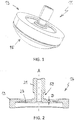
- the in Fig. 1 The weighing foot 11 according to the invention shown comprises a weighing cell 13 according to the invention and a spherical segment-shaped lower part 15 which is designed as a solid body and on which the weighing cell 13 is supported.
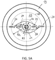
- the load cell 13 comprises a spring body 17 which is monolithic and rotationally symmetrical about a central axis A (cf. Fig. 2 ).
- the spring body 17 comprises an outer bearing ring 19 and an inner force introduction element 21 which projects upwards.
- the outer bearing ring 19 and the inner force introduction element 21 are firmly connected to one another via an annular deformation section 23.
- the connection between the load cell 13 and the lower part 15 is such that the load cell 13 is supported on the lower part 15 via the outer bearing ring 19 and the deformation section 23 is hermetically sealed at the bottom by the lower part 15.
- the annular deformation section 23 is designed as an annular membrane 23.
- the inner force introduction element 21 is designed as a vertically oriented force introduction tube 21, at the upper end of which an external thread is provided, via which the weighing foot 11 can be screwed into a load carrier from below.
- FIG. 3 a diagram is shown which shows the expansion distribution of the spring body 17, ie the expansion of the spring body 17 as a function of the respective radial position.
- the underside of the spring body 17 experiences an extension (positive expansion) under load in the region of the transition to the force introduction tube 21 and in the region of the transition to the outer bearing ring 19 a Compression (negative elongation).
- the curve shown has a zero between the maximum and the minimum.
- This deformation of the spring body 17 can be detected via four strain gauges 27, which are applied to the flat underside of the membrane 23 and are arranged in particular in the two aforementioned areas and whose electrical resistance changes as a function of the strain (cf. Fig. 4 ), two strain gauges 27 being arranged on each of the two opposite sides of the force introduction tube 21.
- the two internal strain gauges 27 are tensile strain gauges that measure the elongation of the diaphragm 23
- the two external strain gauges 27 are compression strain gauges that measure the compression of the diaphragm 27.
- the four strain gauges 27 are electrically connected to a Wheatstone full bridge via bond wires 57 (only one of which is provided with a reference symbol for the sake of clarity), the measuring grids of the strain gauges 27 each being oriented in the radial direction, ie the measuring direction
- the strain gauge 27 is in the radial direction.
- the two inner, tensile strain gauges 27 lie on a first circle 53 with a first radius R1
- the two outer, compressive strain gauges 27 lie on a second circle 55 with a larger second radius R2.
- the four strain gauges 27 are arranged along a common line through the central axis A of the spring body 17. The manufacturing tolerance can be increased by the line arrangement of the strain gauges 27 and the symmetry associated therewith, since at least certain manufacturing deviations can then compensate for one another.
- strain gauges 27 are also slightly different from the line arrangement according to FIG Figure 5A can be placed differently, in particular in such a way that the two inner strain gauges 27 are arranged along a first line and the two outer strain gauges 27 along a second line through the central axis A of the spring body 17, the two lines being slightly rotated relative to one another.
- This makes it possible to reduce the radial distance between the two strain gauges 27 arranged next to one another on one side, so that a spring body 17 with a smaller diameter can be selected, as a result of which the load cell 13 can be made more compact.
- the mentioned advantage of the higher manufacturing tolerance is largely retained, ie if the placement is slightly different.
- the average thickness D of the annular membrane 23 in the area of the smaller first radius R1, ie in the case of the two inner strain gauges 27, is greater than in the area of the second radius R2, that is to say in the case of the two outer strain gauges 27.
- This enables that the same or at least similar expansions are obtained in both areas, so that the resistance / load characteristics of the two inner strain gauges 27 on the one hand and the resistance / load characteristics of the two outer strain gauges 27 on the other hand - despite different radii - at least essentially correspond to each other in terms of amount . This simplifies the evaluation of the bridge voltage of the bridge circuit and increases the accuracy of the load cell 13.
- the greater thickness of the membrane 23 further inside compared to further outside can be justified by the ratios of the area moment of inertia and the distance of the respective area from the force introduction. Is illustrated or simplified in the area of the larger second radius R2 due to the larger circumference requires a small thickness in order to achieve the same material volume and thus an analogous expansion behavior as in the area of the smaller first radius R2 with the smaller circumference.
- the thickness of the membrane 23 decreases monotonically from the inside out, in particular linearly.
- Such a membrane 23 is particularly easy to manufacture.
- other transitions from the larger inner thickness to the smaller outer thickness are also conceivable, for example a step-like decrease.
- the annular membrane 23 On its upper side, the annular membrane 23 has a rounded course in its transition region to the outer bearing ring 19 and in its transition region to the inner force introduction element 21.
- the inner force introduction element 21 has an undercut 59 at its lower end, so that the force is introduced as close as possible to the central axis A of the spring body 17. As a result, the accuracy of the load cell 13 can be significantly improved in each case.
- the strain gauges 27 are electrically connected to an evaluation circuit 41 (cf. Fig. 4 ), which calculates the weight acting on the load cell 13 in each case from the bridge voltage of the strain gauges 27 connected to the full bridge and generates a corresponding output signal.
- the evaluation circuit 41 is arranged inside the force introduction tube 21.
- the output signal of the evaluation circuit 41 can be output externally, for example via a plug 43 which is electrically connected to the evaluation circuit 41, in particular a load carrier, as described above and below.
- the plug 43 is arranged within the force introduction tube 21. If the weighing foot 11 over the Force introduction tube 21 or its external thread is screwed into a load carrier from below, this has the advantage that the output signal can be output directly and by the shortest route to the load carrier or a weighing terminal of the load carrier and displayed there without additional cables or The same are required as would be the case if the output signal were output externally on the bearing ring side.
- Other external interfaces in particular contactless means such as a transmitter, which can be based, for example, on the NFC standard, are also suitable as a further means for the external output of the output signal.
- an internal electrical energy store 45 such as a battery is provided to charge the load cell 13 or the weighing base 11 independently of an external power supply, i.e. self-sufficient to train.
- the electrical energy store 45 is then preferably likewise arranged within the force introduction tube 21.
- Fig. 6 Another embodiment of a spring body 17 is shown. Compared to the spring body 17 according to the 1 to 4 is the membrane 23 of the spring body 17 according to Fig. 6 provided on its upper side with a circumferential annular web 29, which is arranged at least substantially in the center of the membrane 23 in the radial direction. It has been found that this results in the width of the maximum and the width of the minimum of the in Fig. 3 shown expansion distribution of the spring body 17 can be increased. The manufacturing tolerance can be increased.
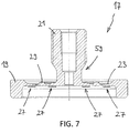
- Fig. 7 Another spring body 17 is shown in a slightly different design.
- the spring body 17 according to Fig. 7 differs from the spring body 17 according to Fig. 2 in that the thickness of the membrane 23 decreases in the area of the two inner strain gauges 27 from the inside to the outside and increases in the area of the two outer strain gauges 27 from the inside to the outside.
- the average thickness D of the membrane 23 in the area of the two inner strain gauges 27 is - and thus according to the invention - greater than the average thickness D of the membrane 23 in the area of the two outer strain gauges 27.
- the circumferential ring web 29 is different from according to the embodiment Fig. 6 less educated.
- FIG. 8 and 9 show two different applications of the inventive weighing foot 11.
- a supermarket shelf 31 is shown with two shelf inserts 33 as examples, each of which is set up on a shelf 35 via, for example, four weighing feet 11.
- the total weight of the respective rack insert 33, including the goods therein, for example bread, can be determined by a respective monitoring device 37, which is connected to all weighing feet 11 of the respective rack insert 33. In this way, the "fill level" of the shelf insert 33 can be monitored. If the total weight of the shelf insert 33 falls below a predetermined value, that is to say, for example, a display integrated in the monitoring device 37 or formed separately from it can light up to indicate this state.
- a predetermined value that is to say, for example, a display integrated in the monitoring device 37 or formed separately from it can light up to indicate this state.
- platforms 39 for example pallets, are shown, as can occur, for example, in a warehouse.
- the platforms 39 are each supported on four weighing feet 11 in order to determine the total weight of the respective platform 39 including the goods arranged thereon. If the same goods are stacked on all platforms 39, the total weights of all platforms can be wired or merged wirelessly, for example via WLAN, which enables a permanent inventory of the respective goods.
Landscapes
- Physics & Mathematics (AREA)
- General Physics & Mathematics (AREA)
- Measurement Of Force In General (AREA)
Priority Applications (2)
| Application Number | Priority Date | Filing Date | Title |
|---|---|---|---|
| EP18214955.9A EP3671142B1 (fr) | 2018-12-20 | 2018-12-20 | Cellule de pesage et pied de pesage |
| US16/723,056 US10935446B2 (en) | 2018-12-20 | 2019-12-20 | Load cell and weighing foot |
Applications Claiming Priority (1)
| Application Number | Priority Date | Filing Date | Title |
|---|---|---|---|
| EP18214955.9A EP3671142B1 (fr) | 2018-12-20 | 2018-12-20 | Cellule de pesage et pied de pesage |
Publications (2)
| Publication Number | Publication Date |
|---|---|
| EP3671142A1 true EP3671142A1 (fr) | 2020-06-24 |
| EP3671142B1 EP3671142B1 (fr) | 2022-11-09 |
Family
ID=64755322
Family Applications (1)
| Application Number | Title | Priority Date | Filing Date |
|---|---|---|---|
| EP18214955.9A Active EP3671142B1 (fr) | 2018-12-20 | 2018-12-20 | Cellule de pesage et pied de pesage |
Country Status (2)
| Country | Link |
|---|---|
| US (1) | US10935446B2 (fr) |
| EP (1) | EP3671142B1 (fr) |
Cited By (1)
| Publication number | Priority date | Publication date | Assignee | Title |
|---|---|---|---|---|
| US11584592B2 (en) | 2020-10-20 | 2023-02-21 | Bizerba SE & Co. KG | Belt tensioner for a conveyor belt |
Families Citing this family (3)
| Publication number | Priority date | Publication date | Assignee | Title |
|---|---|---|---|---|
| EP3671141B1 (fr) * | 2018-12-20 | 2022-08-03 | Bizerba SE & Co. KG | Cellule de pesage et pied de pesage |
| CN112556806B (zh) * | 2020-12-25 | 2024-07-09 | 中国航天空气动力技术研究院 | 测力称重传感器 |
| DK181852B1 (en) * | 2023-04-21 | 2025-02-20 | Nord Modules As | Top module comprising weighing device and method for weighing an object placed on a top module |
Citations (5)
| Publication number | Priority date | Publication date | Assignee | Title |
|---|---|---|---|---|
| EP0351006A2 (fr) * | 1988-07-13 | 1990-01-17 | Philips Patentverwaltung GmbH | Transducteur de pression ou de force utilisant un ressort circulaire à symétrie axiale |
| EP0590713A2 (fr) * | 1992-09-30 | 1994-04-06 | Philips Patentverwaltung GmbH | Transducteur de force utilisant un ressort plane circulaire |
| EP0640813A1 (fr) | 1993-08-25 | 1995-03-01 | Siemens Aktiengesellschaft | Capteur de force à barre annulaire avec des rainures annulaires pour le réglage nominal de la charge |
| WO2000073757A1 (fr) * | 1999-06-01 | 2000-12-07 | Gwt Global Weighing Technologies Gmbh | Diaphragme ondule a symetrie de revolution pour cellule de pesee |
| EP1953514A2 (fr) * | 2007-01-31 | 2008-08-06 | HONDA MOTOR CO., Ltd. | Capteur de force avec amortisseur de choc |
Family Cites Families (7)
| Publication number | Priority date | Publication date | Assignee | Title |
|---|---|---|---|---|
| DE3534608C2 (de) | 1985-09-27 | 1994-10-20 | Vega Grieshaber Gmbh & Co | Anordnung zum Umwandeln von Kräften in elektrische Signale |
| GB8624190D0 (en) | 1986-10-08 | 1986-11-12 | Wahlgren B E G | Strain gauged transducers |
| JP4303091B2 (ja) | 2003-11-10 | 2009-07-29 | ニッタ株式会社 | 歪みゲージ型センサおよびこれを利用した歪みゲージ型センサユニット |
| US7261254B2 (en) | 2004-12-22 | 2007-08-28 | Eastman Kodak Company | Self-regulating media holder |
| DE102007025474B4 (de) | 2007-05-31 | 2011-04-14 | Schenck Process Gmbh | Wägezelle |
| EP3093244B2 (fr) | 2015-05-13 | 2022-01-05 | Bizerba SE & Co. KG | Dispositif de transport de feuille pour une machine d'emballage |
| DE102016117539B4 (de) * | 2016-09-16 | 2024-02-22 | Minebea lntec Bovenden GmbH & Co. KG | Waage mit einer Wägeplattform |
-
2018
- 2018-12-20 EP EP18214955.9A patent/EP3671142B1/fr active Active
-
2019
- 2019-12-20 US US16/723,056 patent/US10935446B2/en active Active
Patent Citations (5)
| Publication number | Priority date | Publication date | Assignee | Title |
|---|---|---|---|---|
| EP0351006A2 (fr) * | 1988-07-13 | 1990-01-17 | Philips Patentverwaltung GmbH | Transducteur de pression ou de force utilisant un ressort circulaire à symétrie axiale |
| EP0590713A2 (fr) * | 1992-09-30 | 1994-04-06 | Philips Patentverwaltung GmbH | Transducteur de force utilisant un ressort plane circulaire |
| EP0640813A1 (fr) | 1993-08-25 | 1995-03-01 | Siemens Aktiengesellschaft | Capteur de force à barre annulaire avec des rainures annulaires pour le réglage nominal de la charge |
| WO2000073757A1 (fr) * | 1999-06-01 | 2000-12-07 | Gwt Global Weighing Technologies Gmbh | Diaphragme ondule a symetrie de revolution pour cellule de pesee |
| EP1953514A2 (fr) * | 2007-01-31 | 2008-08-06 | HONDA MOTOR CO., Ltd. | Capteur de force avec amortisseur de choc |
Cited By (1)
| Publication number | Priority date | Publication date | Assignee | Title |
|---|---|---|---|---|
| US11584592B2 (en) | 2020-10-20 | 2023-02-21 | Bizerba SE & Co. KG | Belt tensioner for a conveyor belt |
Also Published As
| Publication number | Publication date |
|---|---|
| US20200200620A1 (en) | 2020-06-25 |
| EP3671142B1 (fr) | 2022-11-09 |
| US10935446B2 (en) | 2021-03-02 |
Similar Documents
| Publication | Publication Date | Title |
|---|---|---|
| EP3671142B1 (fr) | Cellule de pesage et pied de pesage | |
| EP3671141B1 (fr) | Cellule de pesage et pied de pesage | |
| DE69907423T2 (de) | Druckdifferenzwandler | |
| DE112013002711B4 (de) | Lasterfassungsvorrichtung | |
| DE102008062249A1 (de) | Standfuss für ein Wägezelle | |
| CH705783A1 (de) | WIM Hohlprofil. | |
| DE2021954A1 (de) | Kraftmessring mit einem Dehnungsmesser | |
| EP3149439A1 (fr) | Capteur de couple et procédé pour détecter des couples s'exerçant sur une articulation d'un robot à bras articulé ou dans cette articulation | |
| EP2362201A1 (fr) | Douille de mesure de force ainsi que de dispositif de mesure de force | |
| DE3714613C2 (fr) | ||
| DE102016109433A1 (de) | Kraftsensor | |
| EP3670293B1 (fr) | Système de contrôle automatique | |
| DE3141767A1 (de) | Kraftwandler | |
| DE1773547A1 (de) | Ringfoermige Druckkraftgeberzelle | |
| DE69108715T2 (de) | Kapazitiver kraftsensor. | |
| EP3207348B1 (fr) | Procédé de détermination d'un signal de mesure de pression et capteur de pression correspondant | |
| DE102020001063A1 (de) | Sensorvorrichtung zum Erfassen einer Formveränderung eines Batteriegehäuses | |
| DE102009000255A1 (de) | Messachse | |
| DE102007025474A1 (de) | Wägezelle | |
| DE3325539A1 (de) | Messumformer | |
| DE3039550C2 (de) | Rahmenanordnung für eine Plattformwaage | |
| DE102012016921B4 (de) | Verfahren zur Bestimmung großer Auflasten, insbesondere zur Lagerkraftmessung an Brücken, sowie Vorrichtung zur Durchführung des Verfahrens | |
| DE3226387C2 (fr) | ||
| EP0643287A1 (fr) | Balance plate, en particulier balance pour mesurer la charge d'une roue | |
| EP0640813B1 (fr) | Capteur de force à barre annulaire avec des rainures annulaires pour le réglage nominal de la charge |
Legal Events
| Date | Code | Title | Description |
|---|---|---|---|
| PUAI | Public reference made under article 153(3) epc to a published international application that has entered the european phase |
Free format text: ORIGINAL CODE: 0009012 |
|
| STAA | Information on the status of an ep patent application or granted ep patent |
Free format text: STATUS: THE APPLICATION HAS BEEN PUBLISHED |
|
| AK | Designated contracting states |
Kind code of ref document: A1 Designated state(s): AL AT BE BG CH CY CZ DE DK EE ES FI FR GB GR HR HU IE IS IT LI LT LU LV MC MK MT NL NO PL PT RO RS SE SI SK SM TR |
|
| AX | Request for extension of the european patent |
Extension state: BA ME |
|
| STAA | Information on the status of an ep patent application or granted ep patent |
Free format text: STATUS: REQUEST FOR EXAMINATION WAS MADE |
|
| 17P | Request for examination filed |
Effective date: 20201218 |
|
| RBV | Designated contracting states (corrected) |
Designated state(s): AL AT BE BG CH CY CZ DE DK EE ES FI FR GB GR HR HU IE IS IT LI LT LU LV MC MK MT NL NO PL PT RO RS SE SI SK SM TR |
|
| STAA | Information on the status of an ep patent application or granted ep patent |
Free format text: STATUS: EXAMINATION IS IN PROGRESS |
|
| 17Q | First examination report despatched |
Effective date: 20220301 |
|
| GRAP | Despatch of communication of intention to grant a patent |
Free format text: ORIGINAL CODE: EPIDOSNIGR1 |
|
| STAA | Information on the status of an ep patent application or granted ep patent |
Free format text: STATUS: GRANT OF PATENT IS INTENDED |
|
| INTG | Intention to grant announced |
Effective date: 20220722 |
|
| GRAS | Grant fee paid |
Free format text: ORIGINAL CODE: EPIDOSNIGR3 |
|
| GRAA | (expected) grant |
Free format text: ORIGINAL CODE: 0009210 |
|
| STAA | Information on the status of an ep patent application or granted ep patent |
Free format text: STATUS: THE PATENT HAS BEEN GRANTED |
|
| AK | Designated contracting states |
Kind code of ref document: B1 Designated state(s): AL AT BE BG CH CY CZ DE DK EE ES FI FR GB GR HR HU IE IS IT LI LT LU LV MC MK MT NL NO PL PT RO RS SE SI SK SM TR |
|
| REG | Reference to a national code |
Ref country code: GB Ref legal event code: FG4D Free format text: NOT ENGLISH |
|
| REG | Reference to a national code |
Ref country code: CH Ref legal event code: EP Ref country code: AT Ref legal event code: REF Ref document number: 1530660 Country of ref document: AT Kind code of ref document: T Effective date: 20221115 |
|
| REG | Reference to a national code |
Ref country code: DE Ref legal event code: R096 Ref document number: 502018010994 Country of ref document: DE |
|
| REG | Reference to a national code |
Ref country code: IE Ref legal event code: FG4D Free format text: LANGUAGE OF EP DOCUMENT: GERMAN |
|
| REG | Reference to a national code |
Ref country code: LT Ref legal event code: MG9D |
|
| REG | Reference to a national code |
Ref country code: NL Ref legal event code: MP Effective date: 20221109 |
|
| PG25 | Lapsed in a contracting state [announced via postgrant information from national office to epo] |
Ref country code: SE Free format text: LAPSE BECAUSE OF FAILURE TO SUBMIT A TRANSLATION OF THE DESCRIPTION OR TO PAY THE FEE WITHIN THE PRESCRIBED TIME-LIMIT Effective date: 20221109 Ref country code: PT Free format text: LAPSE BECAUSE OF FAILURE TO SUBMIT A TRANSLATION OF THE DESCRIPTION OR TO PAY THE FEE WITHIN THE PRESCRIBED TIME-LIMIT Effective date: 20230309 Ref country code: NO Free format text: LAPSE BECAUSE OF FAILURE TO SUBMIT A TRANSLATION OF THE DESCRIPTION OR TO PAY THE FEE WITHIN THE PRESCRIBED TIME-LIMIT Effective date: 20230209 Ref country code: LT Free format text: LAPSE BECAUSE OF FAILURE TO SUBMIT A TRANSLATION OF THE DESCRIPTION OR TO PAY THE FEE WITHIN THE PRESCRIBED TIME-LIMIT Effective date: 20221109 Ref country code: FI Free format text: LAPSE BECAUSE OF FAILURE TO SUBMIT A TRANSLATION OF THE DESCRIPTION OR TO PAY THE FEE WITHIN THE PRESCRIBED TIME-LIMIT Effective date: 20221109 Ref country code: ES Free format text: LAPSE BECAUSE OF FAILURE TO SUBMIT A TRANSLATION OF THE DESCRIPTION OR TO PAY THE FEE WITHIN THE PRESCRIBED TIME-LIMIT Effective date: 20221109 |
|
| PG25 | Lapsed in a contracting state [announced via postgrant information from national office to epo] |
Ref country code: RS Free format text: LAPSE BECAUSE OF FAILURE TO SUBMIT A TRANSLATION OF THE DESCRIPTION OR TO PAY THE FEE WITHIN THE PRESCRIBED TIME-LIMIT Effective date: 20221109 Ref country code: PL Free format text: LAPSE BECAUSE OF FAILURE TO SUBMIT A TRANSLATION OF THE DESCRIPTION OR TO PAY THE FEE WITHIN THE PRESCRIBED TIME-LIMIT Effective date: 20221109 Ref country code: LV Free format text: LAPSE BECAUSE OF FAILURE TO SUBMIT A TRANSLATION OF THE DESCRIPTION OR TO PAY THE FEE WITHIN THE PRESCRIBED TIME-LIMIT Effective date: 20221109 Ref country code: IS Free format text: LAPSE BECAUSE OF FAILURE TO SUBMIT A TRANSLATION OF THE DESCRIPTION OR TO PAY THE FEE WITHIN THE PRESCRIBED TIME-LIMIT Effective date: 20230309 Ref country code: HR Free format text: LAPSE BECAUSE OF FAILURE TO SUBMIT A TRANSLATION OF THE DESCRIPTION OR TO PAY THE FEE WITHIN THE PRESCRIBED TIME-LIMIT Effective date: 20221109 Ref country code: GR Free format text: LAPSE BECAUSE OF FAILURE TO SUBMIT A TRANSLATION OF THE DESCRIPTION OR TO PAY THE FEE WITHIN THE PRESCRIBED TIME-LIMIT Effective date: 20230210 |
|
| PG25 | Lapsed in a contracting state [announced via postgrant information from national office to epo] |
Ref country code: NL Free format text: LAPSE BECAUSE OF FAILURE TO SUBMIT A TRANSLATION OF THE DESCRIPTION OR TO PAY THE FEE WITHIN THE PRESCRIBED TIME-LIMIT Effective date: 20221109 |
|
| PG25 | Lapsed in a contracting state [announced via postgrant information from national office to epo] |
Ref country code: SM Free format text: LAPSE BECAUSE OF FAILURE TO SUBMIT A TRANSLATION OF THE DESCRIPTION OR TO PAY THE FEE WITHIN THE PRESCRIBED TIME-LIMIT Effective date: 20221109 Ref country code: RO Free format text: LAPSE BECAUSE OF FAILURE TO SUBMIT A TRANSLATION OF THE DESCRIPTION OR TO PAY THE FEE WITHIN THE PRESCRIBED TIME-LIMIT Effective date: 20221109 Ref country code: EE Free format text: LAPSE BECAUSE OF FAILURE TO SUBMIT A TRANSLATION OF THE DESCRIPTION OR TO PAY THE FEE WITHIN THE PRESCRIBED TIME-LIMIT Effective date: 20221109 Ref country code: DK Free format text: LAPSE BECAUSE OF FAILURE TO SUBMIT A TRANSLATION OF THE DESCRIPTION OR TO PAY THE FEE WITHIN THE PRESCRIBED TIME-LIMIT Effective date: 20221109 Ref country code: CZ Free format text: LAPSE BECAUSE OF FAILURE TO SUBMIT A TRANSLATION OF THE DESCRIPTION OR TO PAY THE FEE WITHIN THE PRESCRIBED TIME-LIMIT Effective date: 20221109 |
|
| REG | Reference to a national code |
Ref country code: CH Ref legal event code: PL |
|
| REG | Reference to a national code |
Ref country code: DE Ref legal event code: R097 Ref document number: 502018010994 Country of ref document: DE |
|
| REG | Reference to a national code |
Ref country code: BE Ref legal event code: MM Effective date: 20221231 |
|
| PG25 | Lapsed in a contracting state [announced via postgrant information from national office to epo] |
Ref country code: SK Free format text: LAPSE BECAUSE OF FAILURE TO SUBMIT A TRANSLATION OF THE DESCRIPTION OR TO PAY THE FEE WITHIN THE PRESCRIBED TIME-LIMIT Effective date: 20221109 Ref country code: LU Free format text: LAPSE BECAUSE OF NON-PAYMENT OF DUE FEES Effective date: 20221220 Ref country code: AL Free format text: LAPSE BECAUSE OF FAILURE TO SUBMIT A TRANSLATION OF THE DESCRIPTION OR TO PAY THE FEE WITHIN THE PRESCRIBED TIME-LIMIT Effective date: 20221109 |
|
| PLBE | No opposition filed within time limit |
Free format text: ORIGINAL CODE: 0009261 |
|
| STAA | Information on the status of an ep patent application or granted ep patent |
Free format text: STATUS: NO OPPOSITION FILED WITHIN TIME LIMIT |
|
| 26N | No opposition filed |
Effective date: 20230810 |
|
| PG25 | Lapsed in a contracting state [announced via postgrant information from national office to epo] |
Ref country code: LI Free format text: LAPSE BECAUSE OF NON-PAYMENT OF DUE FEES Effective date: 20221231 Ref country code: IE Free format text: LAPSE BECAUSE OF NON-PAYMENT OF DUE FEES Effective date: 20221220 Ref country code: CH Free format text: LAPSE BECAUSE OF NON-PAYMENT OF DUE FEES Effective date: 20221231 |
|
| PG25 | Lapsed in a contracting state [announced via postgrant information from national office to epo] |
Ref country code: SI Free format text: LAPSE BECAUSE OF FAILURE TO SUBMIT A TRANSLATION OF THE DESCRIPTION OR TO PAY THE FEE WITHIN THE PRESCRIBED TIME-LIMIT Effective date: 20221109 Ref country code: BE Free format text: LAPSE BECAUSE OF NON-PAYMENT OF DUE FEES Effective date: 20221231 |
|
| PG25 | Lapsed in a contracting state [announced via postgrant information from national office to epo] |
Ref country code: HU Free format text: LAPSE BECAUSE OF FAILURE TO SUBMIT A TRANSLATION OF THE DESCRIPTION OR TO PAY THE FEE WITHIN THE PRESCRIBED TIME-LIMIT; INVALID AB INITIO Effective date: 20181220 |
|
| PG25 | Lapsed in a contracting state [announced via postgrant information from national office to epo] |
Ref country code: CY Free format text: LAPSE BECAUSE OF FAILURE TO SUBMIT A TRANSLATION OF THE DESCRIPTION OR TO PAY THE FEE WITHIN THE PRESCRIBED TIME-LIMIT Effective date: 20221109 |
|
| PG25 | Lapsed in a contracting state [announced via postgrant information from national office to epo] |
Ref country code: MK Free format text: LAPSE BECAUSE OF FAILURE TO SUBMIT A TRANSLATION OF THE DESCRIPTION OR TO PAY THE FEE WITHIN THE PRESCRIBED TIME-LIMIT Effective date: 20221109 Ref country code: IT Free format text: LAPSE BECAUSE OF FAILURE TO SUBMIT A TRANSLATION OF THE DESCRIPTION OR TO PAY THE FEE WITHIN THE PRESCRIBED TIME-LIMIT Effective date: 20221109 |
|
| PG25 | Lapsed in a contracting state [announced via postgrant information from national office to epo] |
Ref country code: MC Free format text: LAPSE BECAUSE OF FAILURE TO SUBMIT A TRANSLATION OF THE DESCRIPTION OR TO PAY THE FEE WITHIN THE PRESCRIBED TIME-LIMIT Effective date: 20221109 |
|
| PG25 | Lapsed in a contracting state [announced via postgrant information from national office to epo] |
Ref country code: MC Free format text: LAPSE BECAUSE OF FAILURE TO SUBMIT A TRANSLATION OF THE DESCRIPTION OR TO PAY THE FEE WITHIN THE PRESCRIBED TIME-LIMIT Effective date: 20221109 |
|
| PG25 | Lapsed in a contracting state [announced via postgrant information from national office to epo] |
Ref country code: BG Free format text: LAPSE BECAUSE OF FAILURE TO SUBMIT A TRANSLATION OF THE DESCRIPTION OR TO PAY THE FEE WITHIN THE PRESCRIBED TIME-LIMIT Effective date: 20221109 |
|
| PG25 | Lapsed in a contracting state [announced via postgrant information from national office to epo] |
Ref country code: MT Free format text: LAPSE BECAUSE OF FAILURE TO SUBMIT A TRANSLATION OF THE DESCRIPTION OR TO PAY THE FEE WITHIN THE PRESCRIBED TIME-LIMIT Effective date: 20221109 |
|
| REG | Reference to a national code |
Ref country code: AT Ref legal event code: MM01 Ref document number: 1530660 Country of ref document: AT Kind code of ref document: T Effective date: 20231220 |
|
| PG25 | Lapsed in a contracting state [announced via postgrant information from national office to epo] |
Ref country code: AT Free format text: LAPSE BECAUSE OF NON-PAYMENT OF DUE FEES Effective date: 20231220 |
|
| PG25 | Lapsed in a contracting state [announced via postgrant information from national office to epo] |
Ref country code: TR Free format text: LAPSE BECAUSE OF FAILURE TO SUBMIT A TRANSLATION OF THE DESCRIPTION OR TO PAY THE FEE WITHIN THE PRESCRIBED TIME-LIMIT Effective date: 20221109 |
|
| PGFP | Annual fee paid to national office [announced via postgrant information from national office to epo] |
Ref country code: GB Payment date: 20251218 Year of fee payment: 8 |
|
| PGFP | Annual fee paid to national office [announced via postgrant information from national office to epo] |
Ref country code: FR Payment date: 20251218 Year of fee payment: 8 |
|
| PGFP | Annual fee paid to national office [announced via postgrant information from national office to epo] |
Ref country code: DE Payment date: 20251222 Year of fee payment: 8 |
|
| PGFP | Annual fee paid to national office [announced via postgrant information from national office to epo] |
Ref country code: AT Payment date: 20260410 Year of fee payment: 5 |