EP3671163A1 - Druckanzeige zur messung eines druckunterschiedes zwischen zwei flüssigkeiten - Google Patents
Druckanzeige zur messung eines druckunterschiedes zwischen zwei flüssigkeiten Download PDFInfo
- Publication number
- EP3671163A1 EP3671163A1 EP19217835.8A EP19217835A EP3671163A1 EP 3671163 A1 EP3671163 A1 EP 3671163A1 EP 19217835 A EP19217835 A EP 19217835A EP 3671163 A1 EP3671163 A1 EP 3671163A1
- Authority
- EP
- European Patent Office
- Prior art keywords
- fluid
- pressure
- capsule
- supplying
- inlet port
- Prior art date
- Legal status (The legal status is an assumption and is not a legal conclusion. Google has not performed a legal analysis and makes no representation as to the accuracy of the status listed.)
- Granted
Links
Images
Classifications
-
- G—PHYSICS
- G01—MEASURING; TESTING
- G01L—MEASURING FORCE, STRESS, TORQUE, WORK, MECHANICAL POWER, MECHANICAL EFFICIENCY, OR FLUID PRESSURE
- G01L13/00—Devices or apparatus for measuring differences of two or more fluid pressure values
- G01L13/02—Devices or apparatus for measuring differences of two or more fluid pressure values using elastically-deformable members or pistons as sensing elements
- G01L13/028—Devices or apparatus for measuring differences of two or more fluid pressure values using elastically-deformable members or pistons as sensing elements using capsules
-
- G—PHYSICS
- G01—MEASURING; TESTING
- G01L—MEASURING FORCE, STRESS, TORQUE, WORK, MECHANICAL POWER, MECHANICAL EFFICIENCY, OR FLUID PRESSURE
- G01L19/00—Details of, or accessories for, apparatus for measuring steady or quasi-steady pressure of a fluent medium insofar as such details or accessories are not special to particular types of pressure gauges
- G01L19/06—Means for preventing overload or deleterious influence of the measured medium on the measuring device or vice versa
- G01L19/0618—Overload protection
Definitions
- the present invention relates to a device for measuring a differential pressure between two fluids, in general for use in networks which convey fluids, in particular fluids of a pressurized hydraulic circuit, for example for performing heating and/or cooling.
- the devices able to measure a pressure of a fluid are also known by the name of pressure gauges.
- Capsule-type pressure gauges are known, where a fluid under pressure (P) enters into a capsule, formed by joining together in a sealed manner two metal membranes, said capsule being deformed owing to the forces which are generated inside the volume enclosed by the two membranes, as occurs for example in an air-filled balloon. The deformation causes a displacement with respect to each other of the membranes which form the walls of the capsule and therefore an expansion of the capsule.
- P-Patm an indication or measurement of the pressure level relative to the atmosphere outside the capsule
- capsules which are particularly sensitive to pressure.
- capsules which are able to measure low pressure levels may be damaged by high pressures, which cause the said capsule to be permanently deformed or to explode.
- differential pressure gauges are also known, these being able to measure a pressure difference between two fluids under pressure.
- the main differential pressure gauges used in hydraulic circuits are double Bourdon tube pressure gauges and magnetic piston pressure gauges.
- the capacity for measuring small differential pressures is greatly limited by the pressure of the two fluids so that, for example, a maximum resolution, for example, of 20 kPa corresponds to an end-of-scale value of the instrument equal to 10 bar, well above the values of 10-30 mbar which are to be measured in the applications described above.
- Magnetic-piston pressure gauges pose a similar problem since, with a reduction in the differential pressure which is to be measured, the dimensions of the piston must be increased, this making the pressure gauges impractical or even unsuitable for use in the field.
- the technical problem which is posed therefore is that of providing a device for measuring a differential pressure between two fluids under pressure which solves or at least partially overcomes the aforementioned problems of the prior art, being able in particular to measure differential pressure values which are very small in relation to the nominal pressure of the two fluids.
- the measurement device or pressure gauge
- the measurement device should be able to measure differential pressures of the order of mbar, also in conditions where the nominal pressure of the two fluids is greater than, for example 5 bars, this being a frequent situation for applications in hydraulic circuits.
- this device In connection with this problem it is also required that this device should have small dimensions, be easy and inexpensive to produce and assemble and be able to be easily installed and used, even by personnel who are not highly specialized.
- a further desirable aspect is that the device should be able to provide a reading of the differential pressure measured which is not hindered in the case where water or liquids containing impurities and/or rich in deposits are used, these tending in particular to soil the reading dial faces of the pressure gauges, preventing reading of the pressure value measured.
- differential pressure gauge and measuring method in which a safety device places in fluid communication the internal chamber with the inlet port for supplying the second fluid to the capsule, for as long as the differential pressure is greater than or equal to a safety value suitable for measurement by means of the said capsule, it is possible to measure a differential pressure very precisely, being able to detect very small pressure difference values, irrespective as to the nominal pressure of the two fluids under pressure which may be greater even by a few orders of magnitude than the differential pressure value to be measured.
- the capsule is preferably formed by at least two metal membranes which are sealingly closed and define an internal volume.
- a unit designed to convert the displacement of a part of the capsule into an indication and/or measurement of the differential pressure comprises preferably a transmission system designed to convert and optionally amplify the translatory displacement of a part of a membrane of the capsule into a rotation of a shaft inside the chamber of the casing.
- the transmission system may comprise a kinematic chain comprising a pin integral with the outer surface of a membrane of the capsule kinematically connected to a segment gear, so that the displacement of the pin causes a proportional rotation of the segment gear about its own axis; a toothed wheel, rotationally integral with the internal shaft, meshing with the segment gear.
- the internal shaft is preferably connected to a measurement indicator element, such as a pointer arranged on a dial face, and/or to measurement acquisition means such as a rotational sensor able to convert the rotation of the internal shaft into an electric signal.
- the pressure gauge comprises also an assembly for transmission of the rotational movement of the internal shaft to a shaft outside the casing, the transmission assembly being preferably of the magnetic transmission type.
- the safety device comprises a safety valve arranged along a capsule supply line between the inlet port for supplying the second fluid and the capsule itself, preferably by means of a connection which is fluid-dynamically connected to a capsule supply line.
- the safety valve preferably comprises a closing member arranged inside a housing, one end of which is in fluid communication with the inlet port supplying the second fluid, wherein the housing further comprises an opening which places it in fluid communication with the internal chamber of the casing, and the closing member is designed to cause opening/closing of the connection between the end of the valve connected to the line supplying the second fluid under pressure and the opening, a passage for the fluid being preferably provided in a peripheral zone of the closing member, in particular of its disc.
- the closing member may for example be movable into an open position against the thrust of spring means pushing against the closing member so as to cause closing of the connection between the inlet port supplying the second fluid and the internal chamber of the casing.
- the capsule is configured to receive inside it a second fluid at a pressure greater than the first pressure of the first fluid, and wherein said deformation of the capsule is an expansion proportional to the pressure difference between said second fluid at a higher pressure and said first fluid at a lower pressure.
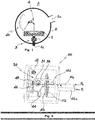
- Fig. 1 shows in schematic form the structure of a differential pressure gauge according to the present invention, which comprises an external casing 2 which defines a chamber 2a sealingly closed with respect to the external environment A and able to be filled with a first fluid at a lower pressure P-, by means of at least one line 2c for supplying the said first fluid to the internal chamber.
- a capsule 1 is inserted inside the internal chamber 2a and is designed to be filled with a second fluid at a higher pressure P+, by means of a inlet port/line 1c for supplying the said second fluid.
- the capsule 1 is generally formed by two membranes which are sealingly closed and is configured to be deformed, in particular to expand, depending on the pressure difference between the pressure P- of the first fluid inside the chamber and the pressure P+ of the second fluid inside the said capsule.
- the device for measuring the differential pressure also comprises a unit 4 able to convert the translatory displacement of at least one membrane of the capsule into an indication or measurement of the value of the differential pressure between the first fluid and the second fluid.
- a safety device 3 is arranged inside the internal chamber 2a and is arranged in fluid communication between the inlet port 1c for supplying the second fluid to the capsule 1 and the capsule 1 itself.
- the safety device therefore allows the pressure to be discharged and the chamber 2a to be filled with the second fluid for as long as said safety value Psaf is not reached. If the differential pressure acting on the two surfaces of a membrane of the capsule (inner towards P+ and outer towards P-) remains less than Psaf, the safety device does not open.
- the safety device closes the connection between the inlet port 1c supplying the second fluid and the internal chamber 2a.
- the capsule in this case would be subject to irreparable damage.
- the safety device ensures the equilibrium of the (internal/external) pressures acting on the capsule should the surfaces of the capsule be even momentarily exposed to a pressure difference such as to damage it (greater than Psaf).
- the safety device opens, allowing filling of the internal chamber 2a also with the second fluid at a pressure P+.
- ⁇ P returns to a value lower than Psaf, the safety device closes and the pressure gauge starts to function normally in the ⁇ P measuring configuration.
- the capsule which may be configured to detect pressure differences which are even very small, independently of the nominal pressure of the two fluids under pressure supplied to the pressure gauge, which may therefore be much greater than the differential pressure range which can be measured by the pressure gauge.
- the solution is therefore particularly suitable for measuring a differential pressure in pressurized hydraulic circuits where the first and second fluids consist of a same fluid flowing in the circuit, drawn off at points of the said circuit where there are different pressures.
- a particular example of such hydraulic circuits are those inside which a single liquid under pressure circulates, for the heating of rooms.
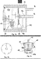
- a preferred example of embodiment of a pressure gauge 100 comprises an external casing 12 which is sealingly closed off from the atmosphere and which defines an internal chamber 12a designed to be filled with a first fluid at a first pressure P-.
- a capsule 11 is arranged inside the chamber 12a and generally comprises two metal membranes 11a, 11b which are sealingly joined together so as to delimit an internal volume and define respective walls of the capsule situated opposite each other in a longitudinal direction X-X.
- the capsule is configured to be deformed depending on the differential pressure between the volume inside the walls 11a,11b and the chamber 12a inside the casing 2, said deformation being generally formed by an increase in the internal volume corresponding to a displacement along the longitudinal direction X-X of at least a part of one or both the walls 11a, 11b of the capsule.
- the casing 12 has, defined thereon, a supply inlet port 12c which is open outwards so as to allow the entry of the first fluid at a (low) pressure P-inside the chamber 12a.
- the casing 12 also has a supply inlet port 11c for supplying the second fluid at a (high) pressure P+ to the capsule via a line 11 d.
- the safety device 30 comprises a safety valve 31 arranged along the capsule supply line 11d between the inlet 11c for supplying the second fluid and the capsule 11 itself, for example by means of a connection 32 which is connected fluid-dynamically to the capsule supply line 11d.
- the safety valve 31 is mounted at the end of the connection 32 and is configured:
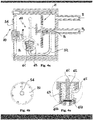
- the safety valve 31 comprises preferably a piston 61 with a disk 61a arranged in a preferably cylindrical housing 63, one end 63a of which is in fluid communication with the connection 32 for the second fluid.
- the housing also comprises an opening 65 which places the housing in fluid communication with the internal chamber 12a of the casing, and the disk 61a of the piston is designed to act as a sealing closing member for opening/closing the connection between the end 63a of the valve connected to the line 11d for the second fluid under pressure and the opening 65, there being preferably provided a passage for the fluid in a peripheral zone 61b of the disk 61a.
- a spring 62 is inserted on the side of the disk 61a opposite to the end 63a of the valve, exerting a thrusting force against the disk 61a and bearing against a wall of the seat.
- the disk 61a is exposed to the fluid under pressure P+ which is supplied from the connection 32 and which pushes against a first surface of the disk 61a opposing the action of the spring 62, and to the pressure P- of the internal chamber 12a which, via the opening 65, enters into the valve housing and pushes against the opposite surface of the disk 61a.
- the following forces are therefore exerted on the piston 61:
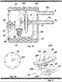
- the pressure gauge according to the invention comprises a transmission system 40 able to amplify and convert the displacement of a membrane 11b of the capsule 11 into a rotation of the shaft 48 inside the chamber 12a of the casing 12, so as to allow the indication and/or the acquisition of a differential pressure value detected.
- the transmission system 40 is formed by a kinematic chain comprising a pin 41 integral with the outer surface of a membrane 11b of the capsule 11, in particular the membrane 11b arranged on the opposite side to the inlet 11d for the second fluid into the said capsule.
- a first rod 44 has a first end connected to the pin 41 by means of a hinge 45 so that the end of the first rod 44 is displaceably integral with the pin 41 and designed to rotate relative to the pin about the axis 45a of the hinge.
- the rotation of the rod 44 causes rotation of a transmission element 44a which is integral with the other end of the first rod 44 which preferably has a substantially L-shaped form.
- the transmission element 44a meshes with a segment gear 46 so that the rotation of the transmission element 44a causes the rotation of the segment gear 46 about its axis 46a.
- a toothed wheel 47 rotationally integral with the internal shaft 48, meshes with the segment gear 46.
- An amplified rotation of the toothed wheel 47, and therefore of the internal shaft 48, corresponds to the rotation of the segment gear 46.
- the internal shaft may be connected to a measurement indicator element, such as a pointer 54, and/or to measurement acquisition means, such as a rotational sensor able to convert a rotation of the shaft into an electric signal.
- a measurement indicator element such as a pointer 54
- measurement acquisition means such as a rotational sensor able to convert a rotation of the shaft into an electric signal.
- the shaft 48 is inside the internal chamber 12a of the casing 12 and is therefore immersed in the first fluid at a pressure P-. If the pointer is immersed in the same internal chamber 12a which is "wetted", the first fluid, which usually contains a lot of dirt and impurities, may make reading of the measurement difficult.
- the pressure gauge according to the invention may comprise an assembly for transmission of the rotational movement of the internal shaft 48 to a shaft 58 outside the casing 12.
- the transmission assembly is preferably of the magnetic transmission type and may for example comprise a magnet 51 integral with the shaft 48 "wetted" inside the casing 12 and having (N/S) polarization in a plane perpendicular to the axis of the shaft, and a magnet 52 which is integral with the external shaft 58 and has an opposite polarization (S/N) which is also perpendicular to the axis of the shaft.
- the rotation of the magnet 51 integral with the internal shaft 48 (due to the expansion of the capsule 11) magnetically drives the magnet 52 integral with the external shaft which is thus rotationally driven about the rotation axis 48a.
- the indication pointer 54 may in this way may be fixed to the external shaft 58 and arranged in a position outside the chamber 12a inside the casing, and a dial face 70 for reading the measurement indicated by the pointer 54 may be kept dry and dirt-free.
- the pressure gauge for measuring a differential pressure between two fluids under pressure is able to ensure an efficient measurement of the differential pressure also in the case of fluids, the nominal pressure of which is much greater than the pressure difference which is to be measured, owing in particular to the use of the detection capsule in combination with the safety device and the means for converting the movement of the membrane of the capsule into an indication and/or measurement of the pressure difference.
- the pressure gauge is simple and economical to assemble and to mount on hydraulic circuits, preferably for performing heating/cooling, or preferably on fluid distribution headers.
- the preferred embodiments of the pressure gauge result in a greater technical advantage since they allow reading of the measurement even in the presence of fluids which contain a lot of impurities and dirt.
- the pressure gauge according to the invention is not limited to the preferred embodiment in which the first fluid supplied to the internal chamber of the casing is at lower pressure and the second fluid supplied to the capsule is at a higher pressure.
- the pressure gauge may in fact also be configured with a pre-deformed, in particular pre-dilated, capsule able to compress when a fluid at a lower pressure is supplied inside the capsule and a fluid at a higher pressure is present inside the internal chamber of the casing.
- the capsule may also be configured so that it is able to both expand and compress, so as to be able to measure both a negative and a positive differential pressure between the first and second fluids.
Landscapes
- Physics & Mathematics (AREA)
- General Physics & Mathematics (AREA)
- Measuring Fluid Pressure (AREA)
Applications Claiming Priority (1)
| Application Number | Priority Date | Filing Date | Title |
|---|---|---|---|
| IT102018000020809A IT201800020809A1 (it) | 2018-12-21 | 2018-12-21 | Manometro per la misura di una pressione differenziale tra due fluidi |
Publications (2)
| Publication Number | Publication Date |
|---|---|
| EP3671163A1 true EP3671163A1 (de) | 2020-06-24 |
| EP3671163B1 EP3671163B1 (de) | 2022-08-03 |
Family
ID=66049514
Family Applications (1)
| Application Number | Title | Priority Date | Filing Date |
|---|---|---|---|
| EP19217835.8A Active EP3671163B1 (de) | 2018-12-21 | 2019-12-19 | Druckanzeige zur messung eines druckunterschiedes zwischen zwei flüssigkeiten |
Country Status (2)
| Country | Link |
|---|---|
| EP (1) | EP3671163B1 (de) |
| IT (1) | IT201800020809A1 (de) |
Citations (3)
| Publication number | Priority date | Publication date | Assignee | Title |
|---|---|---|---|---|
| EP0591564A1 (de) * | 1992-10-05 | 1994-04-13 | WIKA ALEXANDER WIEGAND GmbH & CO. | Manometer |
| US20130008257A1 (en) * | 2009-12-25 | 2013-01-10 | Japan Agency For Marine-Earth Science And Technology | Underwater work device and underwater strain gauge device |
| US9054222B2 (en) * | 2011-03-31 | 2015-06-09 | Endress + Hauser Gmbh + Co. Kg | Pressure resistently encapsulated, pressure difference sensor |
-
2018
- 2018-12-21 IT IT102018000020809A patent/IT201800020809A1/it unknown
-
2019
- 2019-12-19 EP EP19217835.8A patent/EP3671163B1/de active Active
Patent Citations (3)
| Publication number | Priority date | Publication date | Assignee | Title |
|---|---|---|---|---|
| EP0591564A1 (de) * | 1992-10-05 | 1994-04-13 | WIKA ALEXANDER WIEGAND GmbH & CO. | Manometer |
| US20130008257A1 (en) * | 2009-12-25 | 2013-01-10 | Japan Agency For Marine-Earth Science And Technology | Underwater work device and underwater strain gauge device |
| US9054222B2 (en) * | 2011-03-31 | 2015-06-09 | Endress + Hauser Gmbh + Co. Kg | Pressure resistently encapsulated, pressure difference sensor |
Also Published As
| Publication number | Publication date |
|---|---|
| IT201800020809A1 (it) | 2020-06-21 |
| EP3671163B1 (de) | 2022-08-03 |
Similar Documents
| Publication | Publication Date | Title |
|---|---|---|
| US6920795B2 (en) | Adapter for coupling a sensor to a fluid line | |
| CN103842789B (zh) | 可取回的压力传感器 | |
| US20080163668A1 (en) | Leak detector for a pressurized cylinder | |
| US4586383A (en) | Electronic pressure gauge and flow meter | |
| US20090078054A1 (en) | Differential pressure sensor isolation in a process fluid pressure transmitter | |
| CN102822652B (zh) | 可收回的压力传感器 | |
| JP2010530957A (ja) | 管試験方法および装置 | |
| EP1898187B1 (de) | Vorrichtung zum Ermitteln einer Variablen für eine Prozessflüssigkeit mittels Differenzmessung | |
| US2590324A (en) | Temperature compensated means for measuring differential pressures | |
| US3990309A (en) | Temperature compensated pressure limited gauge | |
| US3841158A (en) | Differential pressure transmitter overrange protection | |
| US4523476A (en) | Pressure transducer | |
| US4052903A (en) | Pressure sensor | |
| US5307684A (en) | Stop mechanism for a diaphragm pressure transducer | |
| EP3671163B1 (de) | Druckanzeige zur messung eines druckunterschiedes zwischen zwei flüssigkeiten | |
| US3756085A (en) | Differential pressure transmitter overrange protection | |
| US6993966B2 (en) | Advanced volume gauging device | |
| US6845674B2 (en) | Transfer fluid for pressure measurement technology and its application | |
| US4016760A (en) | Differential flowmeter | |
| RU2007128963A (ru) | Измерение напряжений при компенсации температуры | |
| US3965734A (en) | Pressure equalizing load cell system | |
| GB1558770A (en) | Differential pressure transducers | |
| US2984109A (en) | Device for the protection of pressure measuring elements | |
| US1998996A (en) | Bottom hole pressure bomb | |
| JPH08178783A (ja) | 差圧/圧力伝送器 |
Legal Events
| Date | Code | Title | Description |
|---|---|---|---|
| PUAI | Public reference made under article 153(3) epc to a published international application that has entered the european phase |
Free format text: ORIGINAL CODE: 0009012 |
|
| STAA | Information on the status of an ep patent application or granted ep patent |
Free format text: STATUS: THE APPLICATION HAS BEEN PUBLISHED |
|
| AK | Designated contracting states |
Kind code of ref document: A1 Designated state(s): AL AT BE BG CH CY CZ DE DK EE ES FI FR GB GR HR HU IE IS IT LI LT LU LV MC MK MT NL NO PL PT RO RS SE SI SK SM TR |
|
| AX | Request for extension of the european patent |
Extension state: BA ME |
|
| STAA | Information on the status of an ep patent application or granted ep patent |
Free format text: STATUS: REQUEST FOR EXAMINATION WAS MADE |
|
| 17P | Request for examination filed |
Effective date: 20201203 |
|
| RBV | Designated contracting states (corrected) |
Designated state(s): AL AT BE BG CH CY CZ DE DK EE ES FI FR GB GR HR HU IE IS IT LI LT LU LV MC MK MT NL NO PL PT RO RS SE SI SK SM TR |
|
| GRAP | Despatch of communication of intention to grant a patent |
Free format text: ORIGINAL CODE: EPIDOSNIGR1 |
|
| STAA | Information on the status of an ep patent application or granted ep patent |
Free format text: STATUS: GRANT OF PATENT IS INTENDED |
|
| INTG | Intention to grant announced |
Effective date: 20220311 |
|
| RAP3 | Party data changed (applicant data changed or rights of an application transferred) |
Owner name: WATTS INDUSTRIES ITALIA S.R.L. |
|
| GRAS | Grant fee paid |
Free format text: ORIGINAL CODE: EPIDOSNIGR3 |
|
| GRAA | (expected) grant |
Free format text: ORIGINAL CODE: 0009210 |
|
| STAA | Information on the status of an ep patent application or granted ep patent |
Free format text: STATUS: THE PATENT HAS BEEN GRANTED |
|
| AK | Designated contracting states |
Kind code of ref document: B1 Designated state(s): AL AT BE BG CH CY CZ DE DK EE ES FI FR GB GR HR HU IE IS IT LI LT LU LV MC MK MT NL NO PL PT RO RS SE SI SK SM TR |
|
| REG | Reference to a national code |
Ref country code: AT Ref legal event code: REF Ref document number: 1509100 Country of ref document: AT Kind code of ref document: T Effective date: 20220815 Ref country code: CH Ref legal event code: EP |
|
| REG | Reference to a national code |
Ref country code: DE Ref legal event code: R096 Ref document number: 602019017739 Country of ref document: DE |
|
| REG | Reference to a national code |
Ref country code: IE Ref legal event code: FG4D |
|
| REG | Reference to a national code |
Ref country code: LT Ref legal event code: MG9D |
|
| REG | Reference to a national code |
Ref country code: NL Ref legal event code: MP Effective date: 20220803 |
|
| PG25 | Lapsed in a contracting state [announced via postgrant information from national office to epo] |
Ref country code: SE Free format text: LAPSE BECAUSE OF FAILURE TO SUBMIT A TRANSLATION OF THE DESCRIPTION OR TO PAY THE FEE WITHIN THE PRESCRIBED TIME-LIMIT Effective date: 20220803 Ref country code: RS Free format text: LAPSE BECAUSE OF FAILURE TO SUBMIT A TRANSLATION OF THE DESCRIPTION OR TO PAY THE FEE WITHIN THE PRESCRIBED TIME-LIMIT Effective date: 20220803 Ref country code: PT Free format text: LAPSE BECAUSE OF FAILURE TO SUBMIT A TRANSLATION OF THE DESCRIPTION OR TO PAY THE FEE WITHIN THE PRESCRIBED TIME-LIMIT Effective date: 20221205 Ref country code: NO Free format text: LAPSE BECAUSE OF FAILURE TO SUBMIT A TRANSLATION OF THE DESCRIPTION OR TO PAY THE FEE WITHIN THE PRESCRIBED TIME-LIMIT Effective date: 20221103 Ref country code: NL Free format text: LAPSE BECAUSE OF FAILURE TO SUBMIT A TRANSLATION OF THE DESCRIPTION OR TO PAY THE FEE WITHIN THE PRESCRIBED TIME-LIMIT Effective date: 20220803 Ref country code: LV Free format text: LAPSE BECAUSE OF FAILURE TO SUBMIT A TRANSLATION OF THE DESCRIPTION OR TO PAY THE FEE WITHIN THE PRESCRIBED TIME-LIMIT Effective date: 20220803 Ref country code: LT Free format text: LAPSE BECAUSE OF FAILURE TO SUBMIT A TRANSLATION OF THE DESCRIPTION OR TO PAY THE FEE WITHIN THE PRESCRIBED TIME-LIMIT Effective date: 20220803 Ref country code: FI Free format text: LAPSE BECAUSE OF FAILURE TO SUBMIT A TRANSLATION OF THE DESCRIPTION OR TO PAY THE FEE WITHIN THE PRESCRIBED TIME-LIMIT Effective date: 20220803 Ref country code: ES Free format text: LAPSE BECAUSE OF FAILURE TO SUBMIT A TRANSLATION OF THE DESCRIPTION OR TO PAY THE FEE WITHIN THE PRESCRIBED TIME-LIMIT Effective date: 20220803 |
|
| REG | Reference to a national code |
Ref country code: AT Ref legal event code: MK05 Ref document number: 1509100 Country of ref document: AT Kind code of ref document: T Effective date: 20220803 |
|
| PG25 | Lapsed in a contracting state [announced via postgrant information from national office to epo] |
Ref country code: PL Free format text: LAPSE BECAUSE OF FAILURE TO SUBMIT A TRANSLATION OF THE DESCRIPTION OR TO PAY THE FEE WITHIN THE PRESCRIBED TIME-LIMIT Effective date: 20220803 Ref country code: IS Free format text: LAPSE BECAUSE OF FAILURE TO SUBMIT A TRANSLATION OF THE DESCRIPTION OR TO PAY THE FEE WITHIN THE PRESCRIBED TIME-LIMIT Effective date: 20221203 Ref country code: HR Free format text: LAPSE BECAUSE OF FAILURE TO SUBMIT A TRANSLATION OF THE DESCRIPTION OR TO PAY THE FEE WITHIN THE PRESCRIBED TIME-LIMIT Effective date: 20220803 Ref country code: GR Free format text: LAPSE BECAUSE OF FAILURE TO SUBMIT A TRANSLATION OF THE DESCRIPTION OR TO PAY THE FEE WITHIN THE PRESCRIBED TIME-LIMIT Effective date: 20221104 |
|
| PG25 | Lapsed in a contracting state [announced via postgrant information from national office to epo] |
Ref country code: SM Free format text: LAPSE BECAUSE OF FAILURE TO SUBMIT A TRANSLATION OF THE DESCRIPTION OR TO PAY THE FEE WITHIN THE PRESCRIBED TIME-LIMIT Effective date: 20220803 Ref country code: RO Free format text: LAPSE BECAUSE OF FAILURE TO SUBMIT A TRANSLATION OF THE DESCRIPTION OR TO PAY THE FEE WITHIN THE PRESCRIBED TIME-LIMIT Effective date: 20220803 Ref country code: DK Free format text: LAPSE BECAUSE OF FAILURE TO SUBMIT A TRANSLATION OF THE DESCRIPTION OR TO PAY THE FEE WITHIN THE PRESCRIBED TIME-LIMIT Effective date: 20220803 Ref country code: CZ Free format text: LAPSE BECAUSE OF FAILURE TO SUBMIT A TRANSLATION OF THE DESCRIPTION OR TO PAY THE FEE WITHIN THE PRESCRIBED TIME-LIMIT Effective date: 20220803 Ref country code: AT Free format text: LAPSE BECAUSE OF FAILURE TO SUBMIT A TRANSLATION OF THE DESCRIPTION OR TO PAY THE FEE WITHIN THE PRESCRIBED TIME-LIMIT Effective date: 20220803 |
|
| REG | Reference to a national code |
Ref country code: DE Ref legal event code: R097 Ref document number: 602019017739 Country of ref document: DE |
|
| PG25 | Lapsed in a contracting state [announced via postgrant information from national office to epo] |
Ref country code: SK Free format text: LAPSE BECAUSE OF FAILURE TO SUBMIT A TRANSLATION OF THE DESCRIPTION OR TO PAY THE FEE WITHIN THE PRESCRIBED TIME-LIMIT Effective date: 20220803 Ref country code: EE Free format text: LAPSE BECAUSE OF FAILURE TO SUBMIT A TRANSLATION OF THE DESCRIPTION OR TO PAY THE FEE WITHIN THE PRESCRIBED TIME-LIMIT Effective date: 20220803 |
|
| PLBE | No opposition filed within time limit |
Free format text: ORIGINAL CODE: 0009261 |
|
| STAA | Information on the status of an ep patent application or granted ep patent |
Free format text: STATUS: NO OPPOSITION FILED WITHIN TIME LIMIT |
|
| P01 | Opt-out of the competence of the unified patent court (upc) registered |
Effective date: 20230502 |
|
| PG25 | Lapsed in a contracting state [announced via postgrant information from national office to epo] |
Ref country code: AL Free format text: LAPSE BECAUSE OF FAILURE TO SUBMIT A TRANSLATION OF THE DESCRIPTION OR TO PAY THE FEE WITHIN THE PRESCRIBED TIME-LIMIT Effective date: 20220803 |
|
| 26N | No opposition filed |
Effective date: 20230504 |
|
| REG | Reference to a national code |
Ref country code: CH Ref legal event code: PL |
|
| REG | Reference to a national code |
Ref country code: BE Ref legal event code: MM Effective date: 20221231 |
|
| PG25 | Lapsed in a contracting state [announced via postgrant information from national office to epo] |
Ref country code: SI Free format text: LAPSE BECAUSE OF FAILURE TO SUBMIT A TRANSLATION OF THE DESCRIPTION OR TO PAY THE FEE WITHIN THE PRESCRIBED TIME-LIMIT Effective date: 20220803 Ref country code: LU Free format text: LAPSE BECAUSE OF NON-PAYMENT OF DUE FEES Effective date: 20221219 |
|
| PG25 | Lapsed in a contracting state [announced via postgrant information from national office to epo] |
Ref country code: LI Free format text: LAPSE BECAUSE OF NON-PAYMENT OF DUE FEES Effective date: 20221231 Ref country code: IE Free format text: LAPSE BECAUSE OF NON-PAYMENT OF DUE FEES Effective date: 20221219 Ref country code: CH Free format text: LAPSE BECAUSE OF NON-PAYMENT OF DUE FEES Effective date: 20221231 |
|
| PG25 | Lapsed in a contracting state [announced via postgrant information from national office to epo] |
Ref country code: BE Free format text: LAPSE BECAUSE OF NON-PAYMENT OF DUE FEES Effective date: 20221231 |
|
| PG25 | Lapsed in a contracting state [announced via postgrant information from national office to epo] |
Ref country code: HU Free format text: LAPSE BECAUSE OF FAILURE TO SUBMIT A TRANSLATION OF THE DESCRIPTION OR TO PAY THE FEE WITHIN THE PRESCRIBED TIME-LIMIT; INVALID AB INITIO Effective date: 20191219 |
|
| PG25 | Lapsed in a contracting state [announced via postgrant information from national office to epo] |
Ref country code: CY Free format text: LAPSE BECAUSE OF FAILURE TO SUBMIT A TRANSLATION OF THE DESCRIPTION OR TO PAY THE FEE WITHIN THE PRESCRIBED TIME-LIMIT Effective date: 20220803 |
|
| PG25 | Lapsed in a contracting state [announced via postgrant information from national office to epo] |
Ref country code: MK Free format text: LAPSE BECAUSE OF FAILURE TO SUBMIT A TRANSLATION OF THE DESCRIPTION OR TO PAY THE FEE WITHIN THE PRESCRIBED TIME-LIMIT Effective date: 20220803 |
|
| PG25 | Lapsed in a contracting state [announced via postgrant information from national office to epo] |
Ref country code: MC Free format text: LAPSE BECAUSE OF FAILURE TO SUBMIT A TRANSLATION OF THE DESCRIPTION OR TO PAY THE FEE WITHIN THE PRESCRIBED TIME-LIMIT Effective date: 20220803 |
|
| PG25 | Lapsed in a contracting state [announced via postgrant information from national office to epo] |
Ref country code: TR Free format text: LAPSE BECAUSE OF FAILURE TO SUBMIT A TRANSLATION OF THE DESCRIPTION OR TO PAY THE FEE WITHIN THE PRESCRIBED TIME-LIMIT Effective date: 20220803 Ref country code: MC Free format text: LAPSE BECAUSE OF FAILURE TO SUBMIT A TRANSLATION OF THE DESCRIPTION OR TO PAY THE FEE WITHIN THE PRESCRIBED TIME-LIMIT Effective date: 20220803 |
|
| PG25 | Lapsed in a contracting state [announced via postgrant information from national office to epo] |
Ref country code: BG Free format text: LAPSE BECAUSE OF FAILURE TO SUBMIT A TRANSLATION OF THE DESCRIPTION OR TO PAY THE FEE WITHIN THE PRESCRIBED TIME-LIMIT Effective date: 20220803 |
|
| GBPC | Gb: european patent ceased through non-payment of renewal fee |
Effective date: 20231219 |
|
| PG25 | Lapsed in a contracting state [announced via postgrant information from national office to epo] |
Ref country code: MT Free format text: LAPSE BECAUSE OF FAILURE TO SUBMIT A TRANSLATION OF THE DESCRIPTION OR TO PAY THE FEE WITHIN THE PRESCRIBED TIME-LIMIT Effective date: 20220803 |
|
| PG25 | Lapsed in a contracting state [announced via postgrant information from national office to epo] |
Ref country code: GB Free format text: LAPSE BECAUSE OF NON-PAYMENT OF DUE FEES Effective date: 20231219 |
|
| PG25 | Lapsed in a contracting state [announced via postgrant information from national office to epo] |
Ref country code: GB Free format text: LAPSE BECAUSE OF NON-PAYMENT OF DUE FEES Effective date: 20231219 |
|
| PGFP | Annual fee paid to national office [announced via postgrant information from national office to epo] |
Ref country code: IT Payment date: 20251219 Year of fee payment: 7 |
|
| PGFP | Annual fee paid to national office [announced via postgrant information from national office to epo] |
Ref country code: FR Payment date: 20251226 Year of fee payment: 7 |
|
| PGFP | Annual fee paid to national office [announced via postgrant information from national office to epo] |
Ref country code: DE Payment date: 20251229 Year of fee payment: 7 |