EP3671164A1 - Vorrichtung und verfahren für einen helischen druckminderer - Google Patents
Vorrichtung und verfahren für einen helischen druckminderer Download PDFInfo
- Publication number
- EP3671164A1 EP3671164A1 EP19211776.0A EP19211776A EP3671164A1 EP 3671164 A1 EP3671164 A1 EP 3671164A1 EP 19211776 A EP19211776 A EP 19211776A EP 3671164 A1 EP3671164 A1 EP 3671164A1
- Authority
- EP
- European Patent Office
- Prior art keywords
- diameter
- shank
- defines
- threaded portion
- snubber
- Prior art date
- Legal status (The legal status is an assumption and is not a legal conclusion. Google has not performed a legal analysis and makes no representation as to the accuracy of the status listed.)
- Granted
Links
Images





Classifications
-
- F—MECHANICAL ENGINEERING; LIGHTING; HEATING; WEAPONS; BLASTING
- F16—ENGINEERING ELEMENTS AND UNITS; GENERAL MEASURES FOR PRODUCING AND MAINTAINING EFFECTIVE FUNCTIONING OF MACHINES OR INSTALLATIONS; THERMAL INSULATION IN GENERAL
- F16L—PIPES; JOINTS OR FITTINGS FOR PIPES; SUPPORTS FOR PIPES, CABLES OR PROTECTIVE TUBING; MEANS FOR THERMAL INSULATION IN GENERAL
- F16L55/00—Devices or appurtenances for use in, or in connection with, pipes or pipe systems
- F16L55/04—Devices damping pulsations or vibrations in fluids
- F16L55/045—Devices damping pulsations or vibrations in fluids specially adapted to prevent or minimise the effects of water hammer
-
- F—MECHANICAL ENGINEERING; LIGHTING; HEATING; WEAPONS; BLASTING
- F16—ENGINEERING ELEMENTS AND UNITS; GENERAL MEASURES FOR PRODUCING AND MAINTAINING EFFECTIVE FUNCTIONING OF MACHINES OR INSTALLATIONS; THERMAL INSULATION IN GENERAL
- F16L—PIPES; JOINTS OR FITTINGS FOR PIPES; SUPPORTS FOR PIPES, CABLES OR PROTECTIVE TUBING; MEANS FOR THERMAL INSULATION IN GENERAL
- F16L55/00—Devices or appurtenances for use in, or in connection with, pipes or pipe systems
- F16L55/02—Energy absorbers; Noise absorbers
-
- F—MECHANICAL ENGINEERING; LIGHTING; HEATING; WEAPONS; BLASTING
- F15—FLUID-PRESSURE ACTUATORS; HYDRAULICS OR PNEUMATICS IN GENERAL
- F15B—SYSTEMS ACTING BY MEANS OF FLUIDS IN GENERAL; FLUID-PRESSURE ACTUATORS, e.g. SERVOMOTORS; DETAILS OF FLUID-PRESSURE SYSTEMS, NOT OTHERWISE PROVIDED FOR
- F15B5/00—Transducers converting variations of physical quantities, e.g. expressed by variations in positions of members, into fluid-pressure variations or vice versa; Varying fluid pressure as a function of variations of a plurality of fluid pressures or variations of other quantities
-
- F—MECHANICAL ENGINEERING; LIGHTING; HEATING; WEAPONS; BLASTING
- F16—ENGINEERING ELEMENTS AND UNITS; GENERAL MEASURES FOR PRODUCING AND MAINTAINING EFFECTIVE FUNCTIONING OF MACHINES OR INSTALLATIONS; THERMAL INSULATION IN GENERAL
- F16F—SPRINGS; SHOCK-ABSORBERS; MEANS FOR DAMPING VIBRATION
- F16F15/00—Suppression of vibrations in systems; Means or arrangements for avoiding or reducing out-of-balance forces, e.g. due to motion
- F16F15/02—Suppression of vibrations of non-rotating, e.g. reciprocating systems; Suppression of vibrations of rotating systems by use of members not moving with the rotating systems
-
- F—MECHANICAL ENGINEERING; LIGHTING; HEATING; WEAPONS; BLASTING
- F16—ENGINEERING ELEMENTS AND UNITS; GENERAL MEASURES FOR PRODUCING AND MAINTAINING EFFECTIVE FUNCTIONING OF MACHINES OR INSTALLATIONS; THERMAL INSULATION IN GENERAL
- F16L—PIPES; JOINTS OR FITTINGS FOR PIPES; SUPPORTS FOR PIPES, CABLES OR PROTECTIVE TUBING; MEANS FOR THERMAL INSULATION IN GENERAL
- F16L41/00—Branching pipes; Joining pipes to walls
- F16L41/008—Branching pipes; Joining pipes to walls for connecting a measuring instrument
-
- G—PHYSICS
- G01—MEASURING; TESTING
- G01L—MEASURING FORCE, STRESS, TORQUE, WORK, MECHANICAL POWER, MECHANICAL EFFICIENCY, OR FLUID PRESSURE
- G01L19/00—Details of, or accessories for, apparatus for measuring steady or quasi-steady pressure of a fluent medium insofar as such details or accessories are not special to particular types of pressure gauges
- G01L19/06—Means for preventing overload or deleterious influence of the measured medium on the measuring device or vice versa
- G01L19/0609—Pressure pulsation damping arrangements
-
- G—PHYSICS
- G01—MEASURING; TESTING
- G01L—MEASURING FORCE, STRESS, TORQUE, WORK, MECHANICAL POWER, MECHANICAL EFFICIENCY, OR FLUID PRESSURE
- G01L19/00—Details of, or accessories for, apparatus for measuring steady or quasi-steady pressure of a fluent medium insofar as such details or accessories are not special to particular types of pressure gauges
- G01L19/06—Means for preventing overload or deleterious influence of the measured medium on the measuring device or vice versa
- G01L19/0618—Overload protection
-
- G—PHYSICS
- G01—MEASURING; TESTING
- G01L—MEASURING FORCE, STRESS, TORQUE, WORK, MECHANICAL POWER, MECHANICAL EFFICIENCY, OR FLUID PRESSURE
- G01L19/00—Details of, or accessories for, apparatus for measuring steady or quasi-steady pressure of a fluent medium insofar as such details or accessories are not special to particular types of pressure gauges
- G01L19/0007—Fluidic connecting means
Definitions
- the field of the disclosure relates generally to fluid flow systems and, more specifically, to a system and method for a helical pressure snubber.
- At least some known aircraft include fluid systems, typically hydraulic or pneumatic systems, to channel a fluid, typically air or water, to a plurality of locations within the aircraft.
- the aircraft typically includes a hydraulic system that channels a hydraulic fluid, typically hydraulic oil or water, to at least the landing gear of the aircraft to control and actuate the landing gear.
- the hydraulic fluid is maintained at a high pressure and is capable of transmitting a large force with a small volume of fluid. Changes in pressure of the hydraulic system control and actuate the landing gear.
- the hydraulic system includes a plurality of pressure transducers configured to monitor the pressure of the hydraulic fluid.
- the hydraulic system also includes a plurality of hydraulic mechanisms, such as valves and/or fluid motive equipment, which control the pressure and movement of hydraulic fluid within the hydraulic system. Opening and closing of valves and/or use of other hydraulic mechanisms within the hydraulic system may cause transient pressure spikes within the system.
- One aspect of the present disclosure includes a snubber including a head portion, a shank portion, and a threaded portion.
- the shank portion is attached to the head portion, and the shank portion defines a shank diameter.
- the threaded portion is attached to the shank portion, and the threaded portion includes an external helical thread wrapped around a central shaft.
- the external helical thread defines a threaded diameter, and the central shaft defines a central shaft diameter.
- the shank diameter and the thread diameter are sized such that the shank portion and the threaded portion define at least one fluid flow path when the snubber is installed in a pressure sensor.
- a pressure sensor including a transducer, a fitting, and a snubber.
- the fitting has a first end defining an opening and a threaded portion therein.
- the fitting is coupled to the transducer.
- the threaded portion includes an inner surface and an internal helical thread positioned on the inner surface.
- the first end further defines at least one notch.
- the snubber is positioned within the opening of the threaded portion, and includes a head portion, a shank portion, and a threaded portion.
- the shank portion is attached to the head portion and defines a shank diameter.
- the threaded portion is attached to the shank portion, and includes an external helical thread wrapped around a central shaft.
- the external helical thread defines a thread diameter
- the central shaft defines a central shaft diameter.
- the shank diameter, the thread diameter, and the central shaft diameter are sized such that the notch, the shank portion, and the threaded portion define at least one fluid flow path when the snubber is installed in the fitting.
- a pressure sensor including a transducer, a fitting, and a snubber.
- the fitting has a first end defining an opening and a threaded portion therein.
- the fitting is coupled to the transducer.
- the threaded portion includes an inner surface and an internal helical thread positioned on the inner surface.
- the snubber is positioned within the opening of the threaded portion, and includes a head portion, a shank portion, and a threaded portion.
- the head portion defines at least one notch.
- the shank portion is attached to the head portion and defines a shank diameter.
- the threaded portion is attached to the shank portion, and includes an external helical thread wrapped around a central shaft.
- the external helical thread defines a thread diameter
- the central shaft defines a central shaft diameter.
- the shank diameter, the thread diameter, and the central shaft diameter are sized such that the notch, the shank portion, and the threaded portion define at least one fluid flow path when the snubber is installed in the fitting.
- the pressure sensor includes a transducer and a fitting coupled to the transducer.
- the method includes providing the pressure sensor including a transducer and a fitting.
- the fitting has a first end defining an opening and a threaded portion therein.
- the threaded portion includes an inner surface and an internal helical thread positioned on the inner surface.
- the method also includes filling the threaded portion of the fitting with a fluid.
- the method further includes inserting a snubber into the threaded portion.
- the snubber includes a head portion, a shank portion, and a threaded portion.
- the shank portion is attached to the head portion.
- the head portion defines a notch.
- the shank portion defines a shank diameter.
- the threaded portion is attached to the shank portion and includes an external helical thread wrapped around a central shaft.
- the external helical thread defines a thread diameter and the central shaft defines a central shaft diameter.
- the shank diameter, the thread diameter, and the central shaft diameter are sized such that the notch, the shank portion, and the threaded portion define at least one fluid flow path when the snubber is inserted in the fitting.
- Yet another aspect of the present disclosure includes a method of reducing pressure spikes in a transducer.
- the method includes coupling a pressure sensor to a fluid system.
- the pressure sensor includes a transducer, a fitting coupled to the transducer, and a snubber positioned within the fitting.
- the fitting has a first end defining an opening and a threaded portion therein.
- the threaded portion includes an inner surface and an internal helical thread positioned on the inner surface.
- the snubber includes a head portion, a shank portion, and a threaded portion.
- the shank portion is attached to the head portion, and the head portion defines a notch.
- the shank portion defines a shank diameter.
- the threaded portion is attached to the shank portion and includes an external helical thread wrapped around a central shaft.
- the external helical thread defines a thread diameter
- the central shaft defines a central shaft diameter.
- the shank diameter, the thread diameter, and the central shaft diameter are sized such that the notch, the shank portion, and the threaded portion define at least one fluid flow path when the snubber is inserted in the fitting.
- the method also includes channeling a flow of a fluid into the at least one fluid flow path.
- the method further includes measuring the pressure of the flow of the fluid with the pressure sensor.
- the at least one fluid flow path reduces pressure spikes of the flow of the fluid.
- the pressure sensor includes a transducer and a fitting coupled to the transducer.
- the method includes providing the pressure sensor including a transducer and a fitting.
- the fitting has a first end defining an opening and a threaded portion therein.
- the threaded portion includes an inner surface and an internal helical thread positioned on the inner surface.
- the method also includes filling the threaded portion of the fitting with a fluid.
- the method further includes inserting a snubber into the threaded portion.
- the snubber includes a head portion, a shank portion, and a threaded portion. The shank portion is attached to the head portion, and the head portion defines a notch.
- the shank portion defines a shank diameter.
- the threaded portion is attached to the shank portion.
- the threaded portion includes an external helical thread wrapped around a central shaft.
- the external helical thread defines a thread diameter and the central shaft defines a central shaft diameter.
- the shank diameter, the thread diameter, and the central shaft diameter are sized such that the notch, the shank portion, and the threaded portion define at least one fluid flow path when the snubber is inserted in the fitting.
- the method also includes coupling the pressure sensor to a fluid system.
- Embodiments of the systems and methods described herein include a pressure sensor including a snubber configured to reduce transient pressure spikes detected by the pressure sensor.
- the pressure sensor also includes a transducer and a fitting coupled to the transducer.
- the fitting defines a threaded conduit configured to channel a fluid to the transducer.
- the snubber includes a head portion and a threaded portion.
- the threaded portion and the threaded conduit define at least one fluid flow path when the snubber is installed in the fitting.
- the fluid flow paths are substantially smaller than the threaded conduit and have a substantially higher pressure drop than the threaded conduit.
- the fluid flow paths substantially reduce transient pressure spikes within the transducer and allows the transducer to accurately measure the steady state pressure of the fluid system.
- the snubber protects the transducer by reducing transient pressure spikes measured by the transducer.
- one of the head portion of the snubber and the fitting define one or more notches configured to channel the fluid to the fluid flow paths.
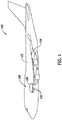
- FIG. 1 is a side view illustration of a vehicle 100.
- vehicle 100 is an aircraft that includes a fuselage 102 and a wing structure 104 extending from fuselage 102.
- Fuselage 102 and/or wing structure 104 define an interior volume 106, and at least one fluid system 108 is positioned within interior volume 106.
- fluid system 108 includes a plurality of pipes 110 configured to channel at least one fluid through interior volume 106 to different parts of vehicle 100.
- fluid system 108 is a hydraulic fluid system configured to control the landing gear of vehicle 100.
- the hydraulic fluid is a hydraulic oil.
- fluid system 108 may be configured to channel any type of fluid and may be configured to control any part of vehicle 100.
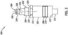
- FIG. 2 is a schematic side view of a pressure sensor 200 for use with fluid system 108.
- FIG. 3 is an exploded perspective view of pressure sensor 200.
- Pressure sensor 200 is configured to be coupled to fluid system 108 and is configured to detect a pressure of a fluid within fluid system 108.
- Pressure sensor 200 includes a transducer 202, a fitting 204, and a snubber 206.
- Transducer 202 is a pressure transducer configured to detect the pressure of the fluid within fluid system 108.
- transducer 202 is configured to detect the pressure of the fluid and convert the detected pressure into an electrical signal. The electrical signal is sent to an electronic system (not shown), typically a control system, to monitor and control fluid system 108.
- Transducer 202 detects the pressure of the fluid by physical deformation of a diaphragm 208 within transducer 202, and an electronic component 210 within transducer 202 detects the deformation and sends an electrical signal to the electronic system (not shown) based on the deformation.
- Transducer 202 has a first end 212 and a second end 214.
- An electrical coupling 216 configured to send the electrical signal to the electronic system is coupled to second end 214 of transducer 202.
- Fitting 204 is configured to couple transducer 202 to fluid system 108, and includes a first end 218 and a second end 220. Second end 220 of fitting 204 is coupled to first end 212 of transducer 202.
- fitting 204 includes a body portion 222 and a coupling portion 224.
- Coupling portion 224 is positioned on second end 220 of fitting 204 and is configured to couple body portion 222 to transducer 202.
- coupling portion 224 includes threading (not shown) configured to attach and retain transducer 202 to fitting 204.
- coupling portion 224 is a hex nut.
- coupling portion 224 may be any fastener that couples body portion 222 to transducer 202.
- body portion 222 is a quick connect fitting configured to quickly connect transducer 202 to fluid system 108.
- body portion 222 is a cylindrical fitting including a shaped outer surface 226 configured to allow a corresponding fitting (not shown) of fluid system 108 to quickly couple fitting 204 to fluid system 108.
- body portion 222 may be any type of fitting that enables pressure sensor 200 to operate as described herein, including without limitation, a threaded fitting.
- First end 218 defines an outer groove 221, and a seal 223 circumscribes fitting 204 and is positioned within outer groove 221
- Body portion 222 defines a conduit 228 configured to channel the fluid to transducer 202.
- first end 218 of body portion 222 defines a first opening 230
- second end 220 of body portion 222 defines a second opening (not shown). Conduit 228 extends from first opening 230 to the second opening.
- Snubber 206 is positioned within conduit 228 and is configured to reduce transient pressure spikes within pressure sensor 200. Specifically, snubber 206 is configured to dampen the pressure exerted by the fluid within fluid system 108 upon transducer 202, such that the maximum transient pressure spikes within fluid system 108 are not transmitted to transducer 202. Specifically, as described below, snubber 206 and body portion 222 define at least one fluid flow path or dampening conduit 232 and 233 (shown in FIG. 4 ) within conduit 228. Fluid flow paths 232 and 233 are substantially smaller than conduit 228 such that the transient pressure of the fluid within fluid system 108 is reduced or dampened prior to reaching transducer 202.
- fluid flow paths 232 and 233 are configured such that the steady state pressure of the fluid within fluid system 108 is accurately determined by transducer 202.
- snubber 206 reduces the transient pressure of the fluid within fluid system 108 while accurately determining the steady state pressure of the fluid within fluid system 108.
- transducer 202 is coupled to fitting 204, and snubber 206 is positioned within conduit 228 of fitting 204.
- Fitting 204 is coupled to fluid system 108 such that the fluid is channeled into fluid flow paths 232 and 233.
- Transducer 202 determines the pressure of the fluid within fluid system 108 while snubber 206 reduces the transient pressure exerted by the fluid within fluid system 108, protecting transducer 202.
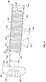
- FIG. 4 is a side view of an exemplary implantation of snubber 206 for use in pressure sensor 200 shown in FIG. 2 .
- Snubber 206 includes a head portion 302, a shank portion 304, and a threaded portion 306.
- Head portion 302 includes a first end 308 and a second end 310, and defines a driving recess (not shown) on first end 308 configured to allow a tool (not shown), typically a screw driver, to rotate snubber 206.
- Shank portion 304 includes a first end 312 and a second end 314, and first end 312 of shank portion 304 is coupled to second end 310 of head portion 302.
- Shank portion 304 is a cylindrical shaft configured to couple head portion 302 to threaded portion 306.
- Shank portion 304 defines a shank diameter 316.
- Threaded portion 306 includes a first end 318 and a second end 320, and first end 318 of threaded portion 306 is coupled to second end 314 of shank portion 304.
- Threaded portion 306 also includes a central shaft 322 and an external helical thread 324.
- Central shaft 322 defines a central shaft diameter 326 and has an outer surface 328.
- External helical thread 324 is a helical thread wrapped around outer surface 328 of central shaft 322.
- External helical thread 324 is a raised helical ridge that defines a crest 330, an external helical thread angle 332, an external helical thread pitch 334, and an external helical thread root 335.
- Crest 330 defines a thread diameter 336
- threaded portion 306 defines a thread length 338.
- Shank diameter 316 defines external helical thread root 335 root between adjacent portions of external helical thread 324.
- Shank diameter 316 and thread diameter 336 are sized such that shank portion 304 and threaded portion 306 define fluid flow paths 232 and 233 when snubber 206 is installed in pressure sensor 200.
- snubber 206 is positioned within conduit 228 such that second end 310 of head portion 302 is flush with first end 218 of fitting 204.
- one or more notches 414 (shown in FIG. 5 ), 502 (shown in FIG. 6 ) are defined respectively in at least one of second end 310 of head portion 302 or first end 218 of fitting 204 and are configured to channel the fluid from fluid system 108 to fluid flow paths 232 and 233.
- notch 414 is defined in second end 310 of head portion 302 and is configured to channel the fluid to fluid flow paths 232 and 233.
- notches 502 are defined in first end 218 of fitting 204 and are configured to channel the fluid into fluid flow paths 232 and 233 and into pressure sensor 200.
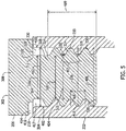
- FIG. 5 is a partial cut-away view of pressure sensor 200 shown in FIG. 2 .
- Conduit 228 includes an inner surface 402 and an internal helical thread 404 positioned on inner surface 402.
- Internal helical thread 404 defines an inner thread diameter 406 and an outer thread diameter 408.
- Internal helical thread 404 defines an internal helical thread pitch 405, an internal helical thread angle 407, and an internal helical thread length 409.
- Conduit 228 also defines a non-threaded portion 410 which defines a non-threaded diameter 412.
- Internal helical thread 404 is configured to receive threaded portion 306 of snubber 206, and non-threaded portion 410 is configured to receive shank portion 304 of snubber 206.
- notch 414 is defined in second end 310 of head portion 302 as described above. In alternative implementations, a plurality of notches 414 may be defined in second end 310 of head portion 302, or solely notches 502 may be used. In the illustrated implementation, notch 414 is a rectangular notch that extends radially inward toward shank portion 304. Notch 414, shank portion 304, non-threaded portion 410, internal helical thread 404, external helical thread root 335, and external helical thread 324 are configured to define fluid flow paths 232 and 233.
- notch 414, shank portion 304, non-threaded portion 410, internal helical thread 404, external helical thread root 335, and external helical thread 324 are configured to define a first fluid flow path 232 and a second fluid flow path 233.
- First fluid flow path 232 is defined by notch 414, shank portion 304, non-threaded portion 410, internal helical thread 404, and external helical thread root 335 such that first fluid flow path 232 is positioned within external helical thread root 335.
- Second fluid flow path 233 is defined by notch 414, shank portion 304, non-threaded portion 410, and external helical thread 324 such that second fluid flow path 233 is positioned on crest 330.
- notch 414, shank portion 304, non-threaded portion 410, internal helical thread 404, external helical thread root 335, and external helical thread 324 define first fluid flow path 232 and second fluid flow path 233 such that first fluid flow path 232 and second fluid flow path 233 have a double helix configuration around central shaft 322.
- Two fluid flow paths provides a redundant path in case one of first fluid flow path 232 and second fluid flow path 233 is obstructed.
- notch 414 and first end 218 of fitting 204 define an entrance 416 of fluid flow paths 232 and 233.
- Shank portion 304 and non-threaded portion 410 define a second portion 417 of fluid flow paths 232 and 233.
- non-threaded diameter 412 is greater than shank diameter 316
- the volume between shank portion 304 and non-threaded portion 410 defines second portion 417 of fluid flow paths 232 and 233.
- Internal helical thread 404 and external helical thread 324 define a threaded portion 418 of fluid flow paths 232 and 233.
- inner thread diameter 406 is greater than central shaft diameter 326
- outer thread diameter 408 is greater than thread diameter 336.
- External helical thread angle 332 substantially corresponds to internal helical thread angle 407
- an external helical thread pitch 334 substantially corresponds to internal helical thread pitch 405.
- the volume between inner thread diameter 406 and central shaft diameter 326 and the volume between outer thread diameter 408 and thread diameter 336 define threaded portion 418 of fluid flow paths 232 and 233.
- fluid flow paths 232 and 233 have a substantially smaller volume than conduit 228.
- fluid flow paths 232 and 233 are substantially smaller in volume than conduit 228 and provide more resistance to the flow through fluid flow paths 232 and 233 than through conduit 228 absent snubber 206. Increased resistance to flow of the fluid also increases the pressure drop through fluid flow paths 232 and 233.
- Increased pressure drop through fluid flow paths 232 and 233 reduces transient pressure spikes within fluid flow paths 232 and 233 by decreasing the pressure of the fluid as it flows through fluid flow paths 232 and 233.
- fluid flow paths 232 and 233 allow static fluid within fluid flow paths 232 and 233, and, as such, the steady state pressure of the fluid is transmitted through fluid flow paths 232 and 233 to transducer 202. Accordingly, fluid flow paths 232 and 233 reduce transient pressure spikes while transmitting the steady state pressure to transducer 202.
- internal helical thread length 409 and thread length 338 are substantially equal.
- threaded portion 306 is also fully installed in internal helical thread 404.
- snubber 206 may be partially installed in fitting 204 such that threaded portion 306 is partially installed in internal helical thread 404, shortening fluid flow paths 232 and 233. Shortening fluid flow paths 232 and 233 decreases resistance to the flow of the flow through fluid flow paths 232 and 233, and decreases the pressure drop through fluid flow paths 232 and 233.
- adjusting the position of snubber 206 within fitting 204 adjusts the pressure drop within fluid flow paths 232 and 233 and increases the range of transient pressure spikes transmitted within fluid flow paths 232 and 233. Accordingly, the range of transient pressure measured by transducer 202 can be tuned by adjusting the position of snubber 206 within fitting 204, protecting transducer 202.
- FIG. 6 is a perspective view of first end 218 of fitting 204 for use in pressure sensor 200 shown in FIG. 2 .
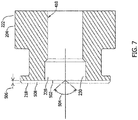
- FIG. 7 is a schematic view of first end 218 of fitting 204 shown in FIG. 6 .
- one or more notches 502 are defined in first end 218 of fitting 204.
- a plurality of notches 502 is defined in first end 218 of fitting 204.
- notches 502 are radially extending channels defined in first end 218 of fitting 204 and are configured to channel the fluid into fluid flow paths 232 and 233.
- notches 502 may have any configuration on first end 218 of fitting 204 that enables pressure sensor 200 to operate as described herein. Additionally, in the illustrated implementation, notches 502 define a V-shape and have a notch angle 504 and a notch depth 506. Notches 502 and second end 310 of head portion 302 define an additional or alternative entrance 508 of fluid flow paths 232 and 233, During operations, the fluid is channeled into entrance 508 of fluid flow paths 232 and 233, and entrance 508 of fluid flow paths 232 and 233 channels the fluid into second portion 417 and threaded portion 418 of fluid flow paths 232 and 233 as described above.
- FIG. 8 is a plot 700 of the pressure measured by pressure sensor 200 shown in FIG. 2 during exemplary operation of fluid system 108.
- Plot 700 includes an x-axis 702 that displays units of time and a y-axis 704 that displays units of pressure.
- a first curve 706 plots the pressure measured by a pressure sensor without snubber 206
- a second curve 708 plots the pressure measured by pressure sensor 200 with snubber 206.
- First curve 706 includes a first transient pressure region 710 and a first steady state pressure region 712
- second curve 708 includes a second transient pressure region 714 and a second steady state pressure region 716.
- First transient pressure region 710 has a substantially higher peak pressures, or transient pressure spikes, 718 than second transient pressure region 714 while first steady state pressure region 712 has a pressure that is substantially equal to second steady state pressure region 716.
- snubber 206 reduces the transient pressure spikes 718 measured by transducer 202 while accurately measuring the steady state pressure. Reducing the peak transient pressure below a predetermined pressure value that does not damage transducer 202 protects transducer 202 and increases the life of transducer 202.
- Pressure sensor 200 is installed into fluid system 108 by first providing pressure sensor 200 including transducer 202, fitting 204, and snubber 206. Second end 220 of fitting 204 is coupled to first end 212 of transducer 202. Conduit 228 is filled with fluid, such as the same fluid used in fluid system 108, to purge the air from conduit 228 and protect transducer 202. Snubber 206 is positioned within conduit 228 by rotating snubber 206 such that external helical thread 324 engages internal helical thread 404 to form fluid flow paths 232 and 233. The fluid used to purge the air from conduit 228 occupies fluid flow paths 232 and 233.
- snubber 206 within conduit 228 is adjusted to tune the pressure drop within fluid flow paths 232 and 233.
- Fitting 204 is attached to a corresponding fitting (not shown) of fluid system 108, coupling transducer 202 and pressure sensor 200 in flow communication within fluid system 108.
- FIG. 9 is a flow diagram of an example of a method 800 of purging air from a pressure sensor.
- the pressure sensor including a transducer and a fitting coupled to the transducer.
- Method 800 includes providing the pressure sensor including a transducer and a fitting.
- the fitting has a first end defining an opening and a threaded portion therein.
- the threaded portion includes an inner surface and an internal helical thread positioned on the inner surface.
- Method 800 also includes filling 802 the threaded portion of the fitting with a fluid.
- Method 800 further includes inserting 804 a snubber into the threaded portion.
- the snubber includes a head portion, a shank portion, and a threaded portion. The shank portion is attached to the head portion.
- the head portion defines a notch.
- the shank portion defines a shank diameter.
- the threaded portion is attached to the shank portion and includes an external helical thread wrapped around a central shaft.
- the external helical thread defines a thread diameter and the central shaft defines a central shaft diameter.
- the shank diameter, the thread diameter, and the central shaft diameter are sized such that the notch, the shank portion, and the threaded portion define a fluid flow path when the snubber is inserted in the fitting.
- FIG. 10 is a flow diagram of an example of a method 900 of reducing pressure spikes in a transducer.
- Method 900 includes coupling 902 a pressure sensor to a fluid system.
- the pressure sensor includes a transducer, a fitting coupled to the transducer, and a snubber positioned within the fitting.
- the fitting has a first end defining an opening and a threaded portion therein.
- the threaded portion includes an inner surface and an internal helical thread positioned on the inner surface.
- the snubber includes a head portion, a shank portion, and a threaded portion.
- the shank portion is attached to the head portion, and the head portion defines a notch.
- the shank portion defines a shank diameter.
- the threaded portion is attached to the shank portion and includes an external helical thread wrapped around a central shaft.
- the external helical thread defines a thread diameter
- the central shaft defines a central shaft diameter.
- the shank diameter, the thread diameter, and the central shaft diameter are sized such that the notch, the shank portion, and the threaded portion define a fluid flow path when the snubber is inserted in the fitting.
- Method 900 also includes channeling 904 a flow of a fluid into the fluid flow path.
- Method 900 further includes measuring 906 the pressure of the flow of the fluid with the pressure sensor. The fluid flow path reduces pressure spikes of the flow of the fluid.
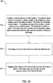
- FIG. 11 is a flow diagram of an example of a method 1000 of installing a pressure sensor in a fluid system.
- the pressure sensor includes a transducer and a fitting coupled to the transducer.
- Method 1000 includes providing the pressure sensor including a transducer and a fitting.
- the fitting has a first end defining an opening and a threaded portion therein.
- the threaded portion includes an inner surface and an internal helical thread positioned on the inner surface.
- Method 1000 also includes filling 1002 the threaded portion of the fitting with a fluid, and more specifically the same fluid used in the fluid system.
- Method 1000 further includes inserting 1004 a snubber into the threaded portion.
- the snubber includes a head portion, a shank portion, and a threaded portion.
- the shank portion is attached to the head portion, and the head portion defines a notch.
- the shank portion defines a shank diameter.
- the threaded portion is attached to the shank portion.
- the threaded portion includes an external helical thread wrapped around a central shaft.
- the external helical thread defines a thread diameter and the central shaft defines a central shaft diameter.
- the shank diameter, the thread diameter, and the central shaft diameter are sized such that the notch, the shank portion, and the threaded portion define a fluid flow path when the snubber is inserted in the fitting.
- Method 1000 also includes coupling 1006 the pressure sensor to a fluid system.
- the pressure sensor including a snubber configured to reduce transient pressure spikes detected by the pressure sensor.
- the pressure sensor also includes a transducer and a fitting coupled to the transducer.
- the fitting defines a threaded conduit configured to channel a fluid to the transducer.
- the snubber includes a head portion and a threaded portion. The threaded portion and the threaded conduit define a fluid flow path when the snubber is installed in the fitting.
- the fluid flow path is substantially smaller than the threaded conduit and has a substantially higher pressure drop than the threaded conduit.
- the fluid flow path substantially reduces transient pressure spikes within the transducer and allows the transducer to accurately measure the steady state pressure of the fluid system.
- the snubber protects the transducer by reducing transient pressure spikes measured by the transducer.
- one of the head portion of the snubber and the fitting define one or more notches configured to channel the fluid to the fluid flow path.
Landscapes
- Engineering & Computer Science (AREA)
- General Engineering & Computer Science (AREA)
- Physics & Mathematics (AREA)
- Mechanical Engineering (AREA)
- General Physics & Mathematics (AREA)
- Fluid Mechanics (AREA)
- Acoustics & Sound (AREA)
- Aviation & Aerospace Engineering (AREA)
- Measuring Fluid Pressure (AREA)
Applications Claiming Priority (1)
| Application Number | Priority Date | Filing Date | Title |
|---|---|---|---|
| US16/224,278 US11041586B2 (en) | 2018-12-18 | 2018-12-18 | System and method for a helical pressure snubber |
Publications (2)
| Publication Number | Publication Date |
|---|---|
| EP3671164A1 true EP3671164A1 (de) | 2020-06-24 |
| EP3671164B1 EP3671164B1 (de) | 2023-01-04 |
Family
ID=68699308
Family Applications (1)
| Application Number | Title | Priority Date | Filing Date |
|---|---|---|---|
| EP19211776.0A Active EP3671164B1 (de) | 2018-12-18 | 2019-11-27 | Vorrichtung und verfahren für einen pressure sensor mit einem helischen druckminderer |
Country Status (6)
| Country | Link |
|---|---|
| US (1) | US11041586B2 (de) |
| EP (1) | EP3671164B1 (de) |
| JP (1) | JP7686369B2 (de) |
| CN (1) | CN111336141B (de) |
| CA (1) | CA3063002C (de) |
| ES (1) | ES2941918T3 (de) |
Families Citing this family (1)
| Publication number | Priority date | Publication date | Assignee | Title |
|---|---|---|---|---|
| US11118992B2 (en) * | 2019-06-06 | 2021-09-14 | Measurement Specialties, Inc. | Pressure sensor assemblies with protective pressure feature |
Citations (7)
| Publication number | Priority date | Publication date | Assignee | Title |
|---|---|---|---|---|
| US3540285A (en) * | 1967-05-03 | 1970-11-17 | Inst Cercetari Si Proiectari P | Apparatus for damping pulsating pressures in pressure gauges |
| US4594877A (en) * | 1984-09-17 | 1986-06-17 | Eg&G Chandler Engineering Company | Pneumatic deadweight tester incorporating dampening means |
| EP0528692A2 (de) * | 1991-08-21 | 1993-02-24 | Halliburton Company | Sensor zur Bohrlochdruckmessung |
| US5343754A (en) * | 1990-12-28 | 1994-09-06 | Hi-Stat Manufacturing Co., Inc. | Pressure transducer |
| WO2006076745A1 (en) * | 2005-01-14 | 2006-07-20 | Mks Instruments, Inc. | A flow defining structure for use with a capacitive pressure sensor |
| JP2017020891A (ja) * | 2015-07-10 | 2017-01-26 | アズビルTaco株式会社 | 圧力センサの構造と、圧力センサを有する装置 |
| JP2017044233A (ja) * | 2015-08-25 | 2017-03-02 | 株式会社ダンレイ | 圧力脈動伝達抑制機構 |
Family Cites Families (10)
| Publication number | Priority date | Publication date | Assignee | Title |
|---|---|---|---|---|
| GB1532015A (en) * | 1976-02-20 | 1978-11-15 | Secretary Industry Brit | Fluid flow restrictors |
| US4637000A (en) * | 1985-06-21 | 1987-01-13 | Western Geophysical Co. Of America | Depth transducer protective assembly |
| US4834108A (en) * | 1986-06-09 | 1989-05-30 | Manresa, Inc. | Blocking filter to prevent air flow into a fluid conduit to a transducer |
| US5236227B1 (en) | 1991-11-12 | 1996-12-03 | Opti Com Manufacturing Network | Assembly for connecting multi-duct conduits having tapered alignment walls |
| US5538293A (en) | 1994-11-18 | 1996-07-23 | Thinking Vents, Inc. | Secondary duct installation apparatus and method for a forced air ventilation system |
| JP3100874B2 (ja) * | 1995-07-24 | 2000-10-23 | 株式会社日本製鋼所 | 中空成形機のクロスヘッド |
| US6231704B1 (en) | 1997-07-14 | 2001-05-15 | David J. Carpinetti | Apparatus for on-site installation of air duct system |
| JP3511909B2 (ja) | 1998-09-24 | 2004-03-29 | トヨタ自動車株式会社 | デフロスタダクトの取付構造 |
| CN202683368U (zh) * | 2012-07-25 | 2013-01-23 | 厦门华最灌溉设备科技有限公司 | 一种流量可调的滴灌头 |
| KR101970613B1 (ko) * | 2017-05-02 | 2019-04-22 | 서암기계공업주식회사 | 에어벤트를 구비한 선반 드레인포트용 니플 |
-
2018
- 2018-12-18 US US16/224,278 patent/US11041586B2/en active Active
-
2019
- 2019-11-26 CA CA3063002A patent/CA3063002C/en active Active
- 2019-11-27 EP EP19211776.0A patent/EP3671164B1/de active Active
- 2019-11-27 ES ES19211776T patent/ES2941918T3/es active Active
- 2019-12-11 JP JP2019223393A patent/JP7686369B2/ja active Active
- 2019-12-16 CN CN201911293620.8A patent/CN111336141B/zh active Active
Patent Citations (7)
| Publication number | Priority date | Publication date | Assignee | Title |
|---|---|---|---|---|
| US3540285A (en) * | 1967-05-03 | 1970-11-17 | Inst Cercetari Si Proiectari P | Apparatus for damping pulsating pressures in pressure gauges |
| US4594877A (en) * | 1984-09-17 | 1986-06-17 | Eg&G Chandler Engineering Company | Pneumatic deadweight tester incorporating dampening means |
| US5343754A (en) * | 1990-12-28 | 1994-09-06 | Hi-Stat Manufacturing Co., Inc. | Pressure transducer |
| EP0528692A2 (de) * | 1991-08-21 | 1993-02-24 | Halliburton Company | Sensor zur Bohrlochdruckmessung |
| WO2006076745A1 (en) * | 2005-01-14 | 2006-07-20 | Mks Instruments, Inc. | A flow defining structure for use with a capacitive pressure sensor |
| JP2017020891A (ja) * | 2015-07-10 | 2017-01-26 | アズビルTaco株式会社 | 圧力センサの構造と、圧力センサを有する装置 |
| JP2017044233A (ja) * | 2015-08-25 | 2017-03-02 | 株式会社ダンレイ | 圧力脈動伝達抑制機構 |
Also Published As
| Publication number | Publication date |
|---|---|
| JP2020118675A (ja) | 2020-08-06 |
| JP7686369B2 (ja) | 2025-06-02 |
| CA3063002A1 (en) | 2020-06-18 |
| CA3063002C (en) | 2023-11-21 |
| CN111336141A (zh) | 2020-06-26 |
| CN111336141B (zh) | 2024-09-17 |
| US11041586B2 (en) | 2021-06-22 |
| EP3671164B1 (de) | 2023-01-04 |
| ES2941918T3 (es) | 2023-05-26 |
| US20200191313A1 (en) | 2020-06-18 |
Similar Documents
| Publication | Publication Date | Title |
|---|---|---|
| EP2301842B1 (de) | Flugzeugfederbein mit Flüssigkeitsstand-Überwachung | |
| DE3513749C1 (de) | Sensor fuer fluidische Systeme | |
| US7552803B2 (en) | Aircraft shock strut having a fluid level monitor | |
| CA2767050C (en) | Tapped insert for cylindrical bore and installation equipment for such insert | |
| US9759335B2 (en) | Flow restrictor having multiple flow modifying regions | |
| US11041586B2 (en) | System and method for a helical pressure snubber | |
| US10288512B2 (en) | Fluid processing apparatus | |
| SE458949B (sv) | Roerkoppling med en kropp och ett gaengat organ foer inboerdes hopskruvning | |
| EP3301423B1 (de) | Überdruckindikator | |
| US10253616B2 (en) | Carrier mechanism and installation method for downhole gauge | |
| EP4097384B1 (de) | Anschlussarmatur für eine ventil- und/oder messkupplung für fluidische systeme zur erfassung von fluiddrücken sowie zur befüllung, entleerung und entlüftung fludischer systeme | |
| US20080309068A1 (en) | Pipe Insert | |
| US20100171361A1 (en) | Tyre Valve | |
| US7107697B2 (en) | Measuring point bolt and method of making the bolt | |
| US10753481B2 (en) | Regulating valve, valve body, and valve stem | |
| CN206449040U (zh) | 一种液压阀阀芯与位移检测器的连接方式 | |
| US7296365B1 (en) | Method and system for inserting a probe | |
| CN112413166A (zh) | 流量阻挡器、流量调节装置以及流量调节方法 | |
| US11686641B2 (en) | Pressure transducer with integral bleed valve | |
| DE102010038881A1 (de) | Sensor zur Erfassung mindestens einer Eigenschaft eines fluiden Mediums | |
| CN208223662U (zh) | 一种用于温度检测器的辅助安装结构 | |
| US6182520B1 (en) | Light probe installation | |
| KR100536820B1 (ko) | 압력게이지 보호용 개폐밸브 | |
| GB2287540A (en) | Pressure pulse reduction device |
Legal Events
| Date | Code | Title | Description |
|---|---|---|---|
| PUAI | Public reference made under article 153(3) epc to a published international application that has entered the european phase |
Free format text: ORIGINAL CODE: 0009012 |
|
| STAA | Information on the status of an ep patent application or granted ep patent |
Free format text: STATUS: THE APPLICATION HAS BEEN PUBLISHED |
|
| AK | Designated contracting states |
Kind code of ref document: A1 Designated state(s): AL AT BE BG CH CY CZ DE DK EE ES FI FR GB GR HR HU IE IS IT LI LT LU LV MC MK MT NL NO PL PT RO RS SE SI SK SM TR |
|
| AX | Request for extension of the european patent |
Extension state: BA ME |
|
| STAA | Information on the status of an ep patent application or granted ep patent |
Free format text: STATUS: REQUEST FOR EXAMINATION WAS MADE |
|
| 17P | Request for examination filed |
Effective date: 20201019 |
|
| RBV | Designated contracting states (corrected) |
Designated state(s): AL AT BE BG CH CY CZ DE DK EE ES FI FR GB GR HR HU IE IS IT LI LT LU LV MC MK MT NL NO PL PT RO RS SE SI SK SM TR |
|
| GRAP | Despatch of communication of intention to grant a patent |
Free format text: ORIGINAL CODE: EPIDOSNIGR1 |
|
| STAA | Information on the status of an ep patent application or granted ep patent |
Free format text: STATUS: GRANT OF PATENT IS INTENDED |
|
| INTG | Intention to grant announced |
Effective date: 20211108 |
|
| GRAJ | Information related to disapproval of communication of intention to grant by the applicant or resumption of examination proceedings by the epo deleted |
Free format text: ORIGINAL CODE: EPIDOSDIGR1 |
|
| STAA | Information on the status of an ep patent application or granted ep patent |
Free format text: STATUS: REQUEST FOR EXAMINATION WAS MADE |
|
| INTC | Intention to grant announced (deleted) | ||
| GRAP | Despatch of communication of intention to grant a patent |
Free format text: ORIGINAL CODE: EPIDOSNIGR1 |
|
| STAA | Information on the status of an ep patent application or granted ep patent |
Free format text: STATUS: GRANT OF PATENT IS INTENDED |
|
| INTG | Intention to grant announced |
Effective date: 20220513 |
|
| GRAS | Grant fee paid |
Free format text: ORIGINAL CODE: EPIDOSNIGR3 |
|
| GRAA | (expected) grant |
Free format text: ORIGINAL CODE: 0009210 |
|
| STAA | Information on the status of an ep patent application or granted ep patent |
Free format text: STATUS: THE PATENT HAS BEEN GRANTED |
|
| AK | Designated contracting states |
Kind code of ref document: B1 Designated state(s): AL AT BE BG CH CY CZ DE DK EE ES FI FR GB GR HR HU IE IS IT LI LT LU LV MC MK MT NL NO PL PT RO RS SE SI SK SM TR |
|
| REG | Reference to a national code |
Ref country code: GB Ref legal event code: FG4D |
|
| REG | Reference to a national code |
Ref country code: CH Ref legal event code: EP |
|
| REG | Reference to a national code |
Ref country code: AT Ref legal event code: REF Ref document number: 1542255 Country of ref document: AT Kind code of ref document: T Effective date: 20230115 |
|
| REG | Reference to a national code |
Ref country code: DE Ref legal event code: R096 Ref document number: 602019023917 Country of ref document: DE |
|
| REG | Reference to a national code |
Ref country code: IE Ref legal event code: FG4D |
|
| RAP4 | Party data changed (patent owner data changed or rights of a patent transferred) |
Owner name: THE BOEING COMPANY |
|
| REG | Reference to a national code |
Ref country code: LT Ref legal event code: MG9D |
|
| REG | Reference to a national code |
Ref country code: NL Ref legal event code: MP Effective date: 20230104 |
|
| REG | Reference to a national code |
Ref country code: ES Ref legal event code: FG2A Ref document number: 2941918 Country of ref document: ES Kind code of ref document: T3 Effective date: 20230526 |
|
| REG | Reference to a national code |
Ref country code: AT Ref legal event code: MK05 Ref document number: 1542255 Country of ref document: AT Kind code of ref document: T Effective date: 20230104 |
|
| P01 | Opt-out of the competence of the unified patent court (upc) registered |
Effective date: 20230516 |
|
| PG25 | Lapsed in a contracting state [announced via postgrant information from national office to epo] |
Ref country code: NL Free format text: LAPSE BECAUSE OF FAILURE TO SUBMIT A TRANSLATION OF THE DESCRIPTION OR TO PAY THE FEE WITHIN THE PRESCRIBED TIME-LIMIT Effective date: 20230104 |
|
| PG25 | Lapsed in a contracting state [announced via postgrant information from national office to epo] |
Ref country code: RS Free format text: LAPSE BECAUSE OF FAILURE TO SUBMIT A TRANSLATION OF THE DESCRIPTION OR TO PAY THE FEE WITHIN THE PRESCRIBED TIME-LIMIT Effective date: 20230104 Ref country code: PT Free format text: LAPSE BECAUSE OF FAILURE TO SUBMIT A TRANSLATION OF THE DESCRIPTION OR TO PAY THE FEE WITHIN THE PRESCRIBED TIME-LIMIT Effective date: 20230504 Ref country code: NO Free format text: LAPSE BECAUSE OF FAILURE TO SUBMIT A TRANSLATION OF THE DESCRIPTION OR TO PAY THE FEE WITHIN THE PRESCRIBED TIME-LIMIT Effective date: 20230404 Ref country code: LV Free format text: LAPSE BECAUSE OF FAILURE TO SUBMIT A TRANSLATION OF THE DESCRIPTION OR TO PAY THE FEE WITHIN THE PRESCRIBED TIME-LIMIT Effective date: 20230104 Ref country code: LT Free format text: LAPSE BECAUSE OF FAILURE TO SUBMIT A TRANSLATION OF THE DESCRIPTION OR TO PAY THE FEE WITHIN THE PRESCRIBED TIME-LIMIT Effective date: 20230104 Ref country code: HR Free format text: LAPSE BECAUSE OF FAILURE TO SUBMIT A TRANSLATION OF THE DESCRIPTION OR TO PAY THE FEE WITHIN THE PRESCRIBED TIME-LIMIT Effective date: 20230104 Ref country code: AT Free format text: LAPSE BECAUSE OF FAILURE TO SUBMIT A TRANSLATION OF THE DESCRIPTION OR TO PAY THE FEE WITHIN THE PRESCRIBED TIME-LIMIT Effective date: 20230104 |
|
| PG25 | Lapsed in a contracting state [announced via postgrant information from national office to epo] |
Ref country code: SE Free format text: LAPSE BECAUSE OF FAILURE TO SUBMIT A TRANSLATION OF THE DESCRIPTION OR TO PAY THE FEE WITHIN THE PRESCRIBED TIME-LIMIT Effective date: 20230104 Ref country code: PL Free format text: LAPSE BECAUSE OF FAILURE TO SUBMIT A TRANSLATION OF THE DESCRIPTION OR TO PAY THE FEE WITHIN THE PRESCRIBED TIME-LIMIT Effective date: 20230104 Ref country code: IS Free format text: LAPSE BECAUSE OF FAILURE TO SUBMIT A TRANSLATION OF THE DESCRIPTION OR TO PAY THE FEE WITHIN THE PRESCRIBED TIME-LIMIT Effective date: 20230504 Ref country code: GR Free format text: LAPSE BECAUSE OF FAILURE TO SUBMIT A TRANSLATION OF THE DESCRIPTION OR TO PAY THE FEE WITHIN THE PRESCRIBED TIME-LIMIT Effective date: 20230405 Ref country code: FI Free format text: LAPSE BECAUSE OF FAILURE TO SUBMIT A TRANSLATION OF THE DESCRIPTION OR TO PAY THE FEE WITHIN THE PRESCRIBED TIME-LIMIT Effective date: 20230104 |
|
| REG | Reference to a national code |
Ref country code: DE Ref legal event code: R097 Ref document number: 602019023917 Country of ref document: DE |
|
| PG25 | Lapsed in a contracting state [announced via postgrant information from national office to epo] |
Ref country code: SM Free format text: LAPSE BECAUSE OF FAILURE TO SUBMIT A TRANSLATION OF THE DESCRIPTION OR TO PAY THE FEE WITHIN THE PRESCRIBED TIME-LIMIT Effective date: 20230104 Ref country code: RO Free format text: LAPSE BECAUSE OF FAILURE TO SUBMIT A TRANSLATION OF THE DESCRIPTION OR TO PAY THE FEE WITHIN THE PRESCRIBED TIME-LIMIT Effective date: 20230104 Ref country code: EE Free format text: LAPSE BECAUSE OF FAILURE TO SUBMIT A TRANSLATION OF THE DESCRIPTION OR TO PAY THE FEE WITHIN THE PRESCRIBED TIME-LIMIT Effective date: 20230104 Ref country code: DK Free format text: LAPSE BECAUSE OF FAILURE TO SUBMIT A TRANSLATION OF THE DESCRIPTION OR TO PAY THE FEE WITHIN THE PRESCRIBED TIME-LIMIT Effective date: 20230104 Ref country code: CZ Free format text: LAPSE BECAUSE OF FAILURE TO SUBMIT A TRANSLATION OF THE DESCRIPTION OR TO PAY THE FEE WITHIN THE PRESCRIBED TIME-LIMIT Effective date: 20230104 |
|
| PLBE | No opposition filed within time limit |
Free format text: ORIGINAL CODE: 0009261 |
|
| STAA | Information on the status of an ep patent application or granted ep patent |
Free format text: STATUS: NO OPPOSITION FILED WITHIN TIME LIMIT |
|
| PG25 | Lapsed in a contracting state [announced via postgrant information from national office to epo] |
Ref country code: SK Free format text: LAPSE BECAUSE OF FAILURE TO SUBMIT A TRANSLATION OF THE DESCRIPTION OR TO PAY THE FEE WITHIN THE PRESCRIBED TIME-LIMIT Effective date: 20230104 |
|
| 26N | No opposition filed |
Effective date: 20231005 |
|
| PG25 | Lapsed in a contracting state [announced via postgrant information from national office to epo] |
Ref country code: SI Free format text: LAPSE BECAUSE OF FAILURE TO SUBMIT A TRANSLATION OF THE DESCRIPTION OR TO PAY THE FEE WITHIN THE PRESCRIBED TIME-LIMIT Effective date: 20230104 |
|
| REG | Reference to a national code |
Ref country code: CH Ref legal event code: PL |
|
| PG25 | Lapsed in a contracting state [announced via postgrant information from national office to epo] |
Ref country code: MC Free format text: LAPSE BECAUSE OF FAILURE TO SUBMIT A TRANSLATION OF THE DESCRIPTION OR TO PAY THE FEE WITHIN THE PRESCRIBED TIME-LIMIT Effective date: 20230104 |
|
| PG25 | Lapsed in a contracting state [announced via postgrant information from national office to epo] |
Ref country code: LU Free format text: LAPSE BECAUSE OF NON-PAYMENT OF DUE FEES Effective date: 20231127 |
|
| PG25 | Lapsed in a contracting state [announced via postgrant information from national office to epo] |
Ref country code: CH Free format text: LAPSE BECAUSE OF NON-PAYMENT OF DUE FEES Effective date: 20231130 |
|
| PG25 | Lapsed in a contracting state [announced via postgrant information from national office to epo] |
Ref country code: MC Free format text: LAPSE BECAUSE OF FAILURE TO SUBMIT A TRANSLATION OF THE DESCRIPTION OR TO PAY THE FEE WITHIN THE PRESCRIBED TIME-LIMIT Effective date: 20230104 Ref country code: LU Free format text: LAPSE BECAUSE OF NON-PAYMENT OF DUE FEES Effective date: 20231127 Ref country code: CH Free format text: LAPSE BECAUSE OF NON-PAYMENT OF DUE FEES Effective date: 20231130 |
|
| REG | Reference to a national code |
Ref country code: BE Ref legal event code: MM Effective date: 20231130 |
|
| REG | Reference to a national code |
Ref country code: IE Ref legal event code: MM4A |
|
| PG25 | Lapsed in a contracting state [announced via postgrant information from national office to epo] |
Ref country code: IE Free format text: LAPSE BECAUSE OF NON-PAYMENT OF DUE FEES Effective date: 20231127 |
|
| PG25 | Lapsed in a contracting state [announced via postgrant information from national office to epo] |
Ref country code: BE Free format text: LAPSE BECAUSE OF NON-PAYMENT OF DUE FEES Effective date: 20231130 |
|
| PG25 | Lapsed in a contracting state [announced via postgrant information from national office to epo] |
Ref country code: IE Free format text: LAPSE BECAUSE OF NON-PAYMENT OF DUE FEES Effective date: 20231127 Ref country code: BE Free format text: LAPSE BECAUSE OF NON-PAYMENT OF DUE FEES Effective date: 20231130 |
|
| PG25 | Lapsed in a contracting state [announced via postgrant information from national office to epo] |
Ref country code: BG Free format text: LAPSE BECAUSE OF FAILURE TO SUBMIT A TRANSLATION OF THE DESCRIPTION OR TO PAY THE FEE WITHIN THE PRESCRIBED TIME-LIMIT Effective date: 20230104 |
|
| PG25 | Lapsed in a contracting state [announced via postgrant information from national office to epo] |
Ref country code: BG Free format text: LAPSE BECAUSE OF FAILURE TO SUBMIT A TRANSLATION OF THE DESCRIPTION OR TO PAY THE FEE WITHIN THE PRESCRIBED TIME-LIMIT Effective date: 20230104 |
|
| PG25 | Lapsed in a contracting state [announced via postgrant information from national office to epo] |
Ref country code: CY Free format text: LAPSE BECAUSE OF FAILURE TO SUBMIT A TRANSLATION OF THE DESCRIPTION OR TO PAY THE FEE WITHIN THE PRESCRIBED TIME-LIMIT; INVALID AB INITIO Effective date: 20191127 |
|
| PG25 | Lapsed in a contracting state [announced via postgrant information from national office to epo] |
Ref country code: HU Free format text: LAPSE BECAUSE OF FAILURE TO SUBMIT A TRANSLATION OF THE DESCRIPTION OR TO PAY THE FEE WITHIN THE PRESCRIBED TIME-LIMIT; INVALID AB INITIO Effective date: 20191127 |
|
| PG25 | Lapsed in a contracting state [announced via postgrant information from national office to epo] |
Ref country code: TR Free format text: LAPSE BECAUSE OF FAILURE TO SUBMIT A TRANSLATION OF THE DESCRIPTION OR TO PAY THE FEE WITHIN THE PRESCRIBED TIME-LIMIT Effective date: 20230104 |
|
| PGFP | Annual fee paid to national office [announced via postgrant information from national office to epo] |
Ref country code: DE Payment date: 20251128 Year of fee payment: 7 |
|
| PGFP | Annual fee paid to national office [announced via postgrant information from national office to epo] |
Ref country code: GB Payment date: 20251127 Year of fee payment: 7 |
|
| PGFP | Annual fee paid to national office [announced via postgrant information from national office to epo] |
Ref country code: IT Payment date: 20251119 Year of fee payment: 7 |
|
| PGFP | Annual fee paid to national office [announced via postgrant information from national office to epo] |
Ref country code: FR Payment date: 20251125 Year of fee payment: 7 |
|
| PGFP | Annual fee paid to national office [announced via postgrant information from national office to epo] |
Ref country code: ES Payment date: 20251201 Year of fee payment: 7 |