EP3671233B1 - Vorrichtung zur kalibrierung einer phasengesteuerten anordnung - Google Patents
Vorrichtung zur kalibrierung einer phasengesteuerten anordnung Download PDFInfo
- Publication number
- EP3671233B1 EP3671233B1 EP18851018.4A EP18851018A EP3671233B1 EP 3671233 B1 EP3671233 B1 EP 3671233B1 EP 18851018 A EP18851018 A EP 18851018A EP 3671233 B1 EP3671233 B1 EP 3671233B1
- Authority
- EP
- European Patent Office
- Prior art keywords
- amplitude
- channel
- coefficient
- phased array
- phase
- Prior art date
- Legal status (The legal status is an assumption and is not a legal conclusion. Google has not performed a legal analysis and makes no representation as to the accuracy of the status listed.)
- Active
Links
Images


Classifications
-
- H—ELECTRICITY
- H01—ELECTRIC ELEMENTS
- H01Q—ANTENNAS, i.e. RADIO AERIALS
- H01Q3/00—Arrangements for changing or varying the orientation or the shape of the directional pattern of the waves radiated from an antenna or antenna system
- H01Q3/26—Arrangements for changing or varying the orientation or the shape of the directional pattern of the waves radiated from an antenna or antenna system varying the relative phase or relative amplitude of energisation between two or more active radiating elements; varying the distribution of energy across a radiating aperture
- H01Q3/267—Phased-array testing or checking devices
-
- G—PHYSICS
- G01—MEASURING; TESTING
- G01R—MEASURING ELECTRIC VARIABLES; MEASURING MAGNETIC VARIABLES
- G01R29/00—Arrangements for measuring or indicating electric quantities not covered by groups G01R19/00 - G01R27/00
- G01R29/08—Measuring electromagnetic field characteristics
- G01R29/10—Radiation diagrams of antennas
-
- G—PHYSICS
- G01—MEASURING; TESTING
- G01R—MEASURING ELECTRIC VARIABLES; MEASURING MAGNETIC VARIABLES
- G01R29/00—Arrangements for measuring or indicating electric quantities not covered by groups G01R19/00 - G01R27/00
- G01R29/08—Measuring electromagnetic field characteristics
-
- G—PHYSICS
- G01—MEASURING; TESTING
- G01R—MEASURING ELECTRIC VARIABLES; MEASURING MAGNETIC VARIABLES
- G01R29/00—Arrangements for measuring or indicating electric quantities not covered by groups G01R19/00 - G01R27/00
- G01R29/08—Measuring electromagnetic field characteristics
- G01R29/0864—Measuring electromagnetic field characteristics characterised by constructional or functional features
- G01R29/0871—Complete apparatus or systems; circuits, e.g. receivers or amplifiers
-
- H—ELECTRICITY
- H01—ELECTRIC ELEMENTS
- H01Q—ANTENNAS, i.e. RADIO AERIALS
- H01Q3/00—Arrangements for changing or varying the orientation or the shape of the directional pattern of the waves radiated from an antenna or antenna system
- H01Q3/26—Arrangements for changing or varying the orientation or the shape of the directional pattern of the waves radiated from an antenna or antenna system varying the relative phase or relative amplitude of energisation between two or more active radiating elements; varying the distribution of energy across a radiating aperture
- H01Q3/2605—Array of radiating elements provided with a feedback control over the element weights, e.g. adaptive arrays
- H01Q3/2611—Means for null steering; Adaptive interference nulling
-
- H—ELECTRICITY
- H01—ELECTRIC ELEMENTS
- H01Q—ANTENNAS, i.e. RADIO AERIALS
- H01Q3/00—Arrangements for changing or varying the orientation or the shape of the directional pattern of the waves radiated from an antenna or antenna system
- H01Q3/26—Arrangements for changing or varying the orientation or the shape of the directional pattern of the waves radiated from an antenna or antenna system varying the relative phase or relative amplitude of energisation between two or more active radiating elements; varying the distribution of energy across a radiating aperture
- H01Q3/2682—Time delay steered arrays
-
- H—ELECTRICITY
- H04—ELECTRIC COMMUNICATION TECHNIQUE
- H04B—TRANSMISSION
- H04B17/00—Monitoring; Testing
- H04B17/10—Monitoring; Testing of transmitters
- H04B17/11—Monitoring; Testing of transmitters for calibration
- H04B17/12—Monitoring; Testing of transmitters for calibration of transmit antennas, e.g. of the amplitude or phase
-
- H—ELECTRICITY
- H04—ELECTRIC COMMUNICATION TECHNIQUE
- H04W—WIRELESS COMMUNICATION NETWORKS
- H04W24/00—Supervisory, monitoring or testing arrangements
-
- H—ELECTRICITY
- H04—ELECTRIC COMMUNICATION TECHNIQUE
- H04W—WIRELESS COMMUNICATION NETWORKS
- H04W24/00—Supervisory, monitoring or testing arrangements
- H04W24/06—Testing, supervising or monitoring using simulated traffic
Definitions
- This application relates to the communications field, and in particular, to a phased array correction and testing method and a correction and testing apparatus.
- a basic principle of a phased array is to implement power combination and beam scanning through superposition and phase variation of radiation waveforms of element antennas.
- Radiation performance of the phased array mainly depends on the element antennas and a beam control system, and is represented by a far-field directivity pattern. Due to a small spacing and strong mutual coupling between antenna elements of a phased array antenna, the phased array antenna has a decreased antenna gain and a raised side lobe level, and in a severe case, not only accurate beam scanning cannot be implemented, but also severe beam distortion may occur.
- Performance of a phased array may be affected by many factors, including device inconsistency in a channel error, a manufacturing tolerance, an assembly error, an environmental change, mutual coupling between array elements, a location deviation, a channel failure, and the like. Therefore, phased array correction, fault determining and locating, performance evaluation, maintenance-type correction, and testing are all very important.
- a conventional phased array antenna testing method is a remote field testing method. Specifically, a to-be-tested antenna apparatus is placed on a three-dimensionally rotating turntable, a test probe is placed at a far-field position of the to-be-tested antenna, and as the turntable rotates, all indicators of the antenna apparatus are tested through frequency sweeping.
- the remote field testing method usually requires a relatively large test space. This sets a limitation on a test site, and makes testing inconvenient. In addition, if there is a large batch of antenna apparatuses, it takes much time to test each element in the antenna apparatuses, resulting in low testing efficiency.
- WO 2016/022202A1 provides techniques and systems for performing near-field array antenna calibration are described herein that are capable of significantly reducing negative effects of multipath and other error mechanisms in the near-field of an array antenna under test(AUT). For each individual element of the AUT, measurements are made using signals sent from multiple different probe locations in the near-field. The measurements are then combined in a manner that de-correlates multipath and other error signals in the near field.
- Embodiments of this application provide a phased array correction and testing method and a correction and testing apparatus, to improve test efficiency, reduce a floor area, and lower costs, thereby greatly reducing time required for phased array correction and improving test efficiency of a phased array product.
- a first aspect of the embodiments of this application provides a phased array correction and testing method.
- a correction and testing apparatus including a first phased array and a second phased array is mainly used.
- the first phased array is a to-be-tested phased array, and specifically, may be a to-be-tested phased array antenna.
- the second phased array is a mirror array for correction and testing.
- the first phased array includes at least one first RF channel
- the second phased array includes at least one second RF channel
- a quantity of the second RF channels in the second phased array needs to be greater than or equal to a quantity of the first RF channels, so that a topology of each first RF channel can correspond to a topology of a second RF channel, and the two are in mirror symmetry.
- the first RF channel and the second RF channel are coupled face to face.
- the topology herein is a hardware structure, including, for example, a spacing between a first RF channel and a second RF channel, the quantity of the first RF channels, and the quantity of the second RF channels.
- the quantity of the second RF channels is greater than the quantity of the first RF channels, there are redundant second RF channels not in mirror symmetry with a first RF channel. It may be understood that a radiation front of the first phased array and a radiation front of the second phased array are spaced by a subwavelength distance. An order of magnitude of a subwavelength is nanometer, and therefore the second phased array are spaced by a subwavelength distance. An order of magnitude of a subwavelength is nanometer, and therefore the subwavelength is shorter than a wavelength.
- the correction and testing apparatus receives, through the second RF channel of the second phased array, a coupling signal sent through the first RF channel of the first phased array; then, may determine an amplitude value and a phase value of the first RF channel based on the coupling signal; and subsequently, calculates, based on the amplitude value, the phase value, and standard metering data, an amplitude deviation value and a phase deviation value that correspond to the first RF channel.
- the correction and testing apparatus needs to correct amplitude coefficients and phase coefficients that correspond to all first RF channels, and obtain the corrected target amplitude coefficients and the corrected target phase coefficients.
- the correction and testing apparatus may test the first phased array by using the target amplitude coefficient and the target phase coefficient, and obtain performance indicator parameters corresponding to the first phased array, such as an equivalent isotropically radiated power, an error vector amplitude, and a bit error rate.
- the phased array correction and testing method is provided.
- the method is mainly applied to the correction and testing apparatus.
- the correction and testing apparatus includes the first phased array and the second phased array.
- the first phased array includes the first radio frequency RF channel
- the second phased array includes the second RF channel
- the first RF channel has a correspondence with the second RF channel
- the radiation front of the second phased array and the radiation front of the first phased array are spaced by the subwavelength distance.
- the correction and testing apparatus receives, through the second RF channel, the coupling signal sent through the first RF channel; and then, determines, based on the coupling signal, the amplitude deviation value and the phase deviation value that correspond to the first RF channel.
- the correction and testing apparatus needs to correct an amplitude coefficient and a phase coefficient that correspond to the first RF channel to obtain a target amplitude coefficient and a target phase coefficient.
- the correction and testing apparatus may measure the performance indicator parameters of the first phased array by using the target amplitude coefficient and the target phase coefficient.
- a calibrated mirror phased array and a to-be-tested phased array are disposed face to face by a subwavelength distance, and fast amplitude-phase correction is performed on all RF channels of the to-be-tested phased array by using a face-to-face direct coupling mechanism between antenna array elements, thereby improving test efficiency, reducing a floor area, and lowering costs.
- This can greatly reduce time required for phased array correction and improve test efficiency of a phased array product.
- the first phased array includes a plurality of first RF channels
- the second phased array includes a plurality of second RF channels
- the receiving, through the second RF channel of the second phased array, a coupling signal sent through the first RF channel may include the following steps:
- the second phased array is mounted on a fixed assembly line test platform as a standard correction and testing device of the first phased array.
- all second RF channels that are in the second phased array of the correction and testing apparatus and that are directly coupled to the first RF channels are in an off state.
- a matrix of switches performs on-off control on each second RF channel of the second phased array.
- the matrix of switches includes a plurality of switches, and one switch is connected to one second RF channel.
- an attenuator is further provided at each switch, and the attenuator can prevent excessively high power.
- the second RF channels may be switched on one by one in a specific order.
- the first phased array includes nine first RF channels
- the second phased array also includes nine second RF channels
- the second RF channels are sequentially numbered 1 to 9.
- the nine second RF channels are all in an off state.
- the No. 1 second RF channel is first switched on, a coupling signal sent through a No. 1 first RF channel that corresponds to the No. 1 second RF channel is received through the No. 1 second RF channel, and then the No. 1 second RF channel is switched off; next, the No. 2 second RF channel is switched on, and a coupling signal sent through a No. 2 first RF channel that corresponds to the No. 2 second RF channel is received through the No. 2 second RF channel; and the process proceeds until coupling signals from the nine first RF channels are all received.
- the receiving, through a second RF channel, a coupling signal sent through each first RF channel may include the following steps:
- n th second RF channel in the second RF channels is switched on, where n is a positive integer, and n is not greater than the total quantity of the first RF channels.
- the correction and testing apparatus receives, through the n th second RF channel, a coupling signal sent through an n th first RF channel.
- the n th second RF channel herein also has a mirror symmetry relationship with the n th first RF channel.
- the first step to the third step may be used to detect any coupling signal sent through a first RF channel in the first phased array, all the first RF channels in the first phased array may send coupling signals by using the foregoing three steps, until the coupling signals sent through the first RF channels are all received through the second RF channels.
- this embodiment of this application describes how the second RF channel receives the coupling signal from the first RF channel. Description is made by using a group of first RF channels and second RF channels corresponding thereto as an example. Amplitude-phase correction and measurement can be performed on the to-be-tested phased array in a one-by-one manner by using a similar method. That is, correction and testing can be performed on each first RF channel. Compared with performing correction and testing on a plurality of RF channels simultaneously, this application helps to improve accuracy of correction and testing.
- the determining, by the correction and testing apparatus based on the coupling signal, an amplitude deviation value and a phase deviation value that correspond to the first RF channel may specifically include the following steps:
- a vector network analysis instrument in the correction and testing apparatus may detect, based on the obtained coupling signal, the amplitude value and the phase value that correspond to the first RF channel. It may be understood that usually, the amplitude value and the phase value are specific to each first RF channel. However, in actual application, the amplitude value and the phase value may alternatively be specific to a plurality of first RF channels. Description is made by using an amplitude value and a phase value of a first RF channel as an example. However, this does not constitute a limitation on this solution.
- the amplitude value and the phase value that correspond to the first RF channel are obtained based on the coupling signal, and then the required amplitude deviation value and the required phase deviation value are calculated by using the preset amplitude value and the preset phase value respectively.
- deviation values between the currently measured amplitude and phase values and the preset amplitude and phase values can be obtained, and the deviation values are used to determine whether the RF channel has an exception or a fault, thereby helping to improve applicability and operability of the solution.
- the correction and testing apparatus may further perform the following steps:
- the correction and testing apparatus determines whether an absolute value of the amplitude deviation value falls within a preset amplitude error range, and whether an absolute value of the phase deviation value falls within a preset phase error range. If the two conditions are satisfied, the correction and testing apparatus may determine that the amplitude deviation value and the phase deviation value satisfy the preset error correction condition.
- the preset amplitude error range is greater than or equal to 10 decibels
- the preset phase error range is greater than or equal to 5 degrees
- amplitude deviation values of nine first RF channels are respectively 12 decibels, 5 decibels, 11 decibels, 10 decibels, 5 decibels, 3 decibels, 7 decibels, 4 decibels, and 19 decibels.
- the largest amplitude deviation value is 19 decibels that is greater than 10 decibels. Therefore, it is determined that the absolute value of the amplitude deviation value falls within the preset amplitude error range.
- Phase deviation values of the nine first RF channels are respectively 3 degrees, 5 degrees, 8 degrees, 1 degree, 1 degree, 3 degrees, 7 degrees, 10 degrees, and 6 degrees. Upon comparison, it is found that the largest phase deviation value is 10 degrees that is greater than 5 degrees. Therefore, it is determined that the absolute value of the phase deviation value falls within the preset phase error range. In this case, it indicates that the preset error correction condition is currently satisfied.
- the preset error correction condition is not satisfied, it is considered that the RF channel has a channel fault, subsequent channel amplitude-phase correction and testing is not performed, and the first phased array is directly disassembled from the second phased array by using a mechanical arm, and returned for corrective maintenance. Therefore, this helps to find whether a fault occurs in the to-be-tested phased array as early as possible, thereby improving applicability of the solution.
- the correction and testing apparatus may further perform the following steps:
- the correction and testing apparatus obtains a first position vector of the first RF channel in a space and a second position vector of the second RF channel in the space; then, determines the amplitude coefficient and the phase coefficient based on the first position vector and the second position vector; and finally, calculates, by using a relevant formula, a coupling coefficient based on a near-field electric field generated by the first RF channel, a near-field electric field generated by the second RF channel, the amplitude coefficient, and the phase coefficient.
- the first position vector and the second position vector may be further obtained, and then the coupling coefficient is calculated based on a series of parameters. In the foregoing manner, a more accurate coupling coefficient can be obtained and is used in subsequent RF channel correction and testing, thereby improving feasibility of the solution.
- the correcting, by the correction and testing apparatus, an amplitude coefficient and a phase coefficient that correspond to the first RF channel to obtain a target amplitude coefficient and a target phase coefficient specifically includes the following steps:
- a front of the first phased array and a front of the second phased array may be kept in parallel, and in this case, the correction and testing apparatus may train the amplitude coefficient and the phase coefficient by using a preset relationship model, where the preset relationship model is a functional relationship model between the coupling coefficient and a parallel deviation position. Then, the correction and testing apparatus can obtain the trained target amplitude coefficient and the trained target phase coefficient.
- this embodiment of this application describes how to obtain the target amplitude coefficient and the target phase coefficient when the first phased array and the second phased array are parallel to each other. That is, the obtained amplitude coefficient and the obtained phase coefficient are trained by using the preset relationship model.
- the functional relationship model between the coupling coefficient and the parallel deviation position is set up by using an artificial neural network model, and the amplitude coefficient and the phase coefficient are corrected based on measured data by using an artificial intelligence learning algorithm, to obtain the corresponding target amplitude coefficient and the corresponding target phase coefficient, thereby improving correction precision of each first RF channel.
- the front of the first phased array is not parallel to the front of the second phased array, and then the correction and testing apparatus corrects the amplitude coefficient and the phase coefficient that correspond to the first RF channel to obtain the target amplitude coefficient and the target phase coefficient.
- This step may specifically include the following operations:
- the correction and testing apparatus obtains an included angle between the front of the first phased array and the front of the second phased array, and determines how to correct the amplitude coefficient and the phase coefficient based on a value of the included angle.
- the correction and testing apparatus may calculate the target amplitude coefficient based on a first amplitude correction coefficient and the amplitude coefficient, and may calculate the target phase coefficient based on a first phase correction coefficient and the phase coefficient, where the first amplitude correction coefficient represents preset amplitude correction coefficients in different directions (for example, an x-axis, a y-axis, and a z-axis), and the first phase correction coefficient represents preset phase correction coefficients in different directions (for example, an x-axis, a y-axis, and a z-axis).
- the correction and testing apparatus calculates the target amplitude coefficient based on the first amplitude correction coefficient, a second amplitude correction coefficient, and the amplitude coefficient, and calculates the target phase coefficient based on the first phase correction coefficient, a second phase correction coefficient, and the phase coefficient, where the second amplitude correction coefficient represents an amplitude correction coefficient of coupling between the first RF channel and the corresponding second RF channel, and the second phase correction coefficient represents a phase correction coefficient of coupling between the first RF channel and the corresponding second RF channel.
- this embodiment of this application describes how to obtain the target amplitude coefficient and the target phase coefficient when the first phased array and the second phased array are not parallel to each other. That is, an included angle between the front of the first phased array and the front of the second phased array is obtained first, and a corresponding correction manner is selected based on a type of the included angle. In the foregoing manner, the amplitude coefficient and the phase coefficient are corrected based on measured data by using the amplitude correction coefficient and the phase correction coefficient, to obtain the corresponding target amplitude coefficient and the corresponding target phase coefficient, thereby improving correction precision of each first RF channel.
- the correction and testing apparatus may further perform the following step:
- the correction and testing apparatus may further determine a beam directivity pattern of the first phased array based on the target amplitude coefficient and the target phase coefficient.
- a beam means a shape formed on the surface of the earth by an electromagnetic wave emitted by a satellite antenna, and mainly includes a global beam, a dot-shaped beam, and a shaped beam. Their shapes depend on a transmit antenna.
- the beam directivity pattern may include a horizontal beam width and a vertical beam width.
- a beam width may be an included angle between two half-power points of a beam, and is related to an antenna gain.
- a higher antenna gain means a narrower beam and a higher search angle resolution.
- the horizontal beam width means an included angle between two directions in which a radiated power is reduced by 3 decibels on both sides of a maximum radiation direction in a horizontal direction.
- the vertical beam width means an included angle between two directions in which a radiated power is reduced by 3 dB on both sides of a maximum radiation direction in a vertical direction.
- a backend processing device of the second phased array can be used to perform online monitoring on the performance indicator parameters of the first phased array, but also the target phase coefficient and the target amplitude coefficient can be used to determine the beam directivity pattern corresponding to the first phased array, to predict the beam directivity pattern of the to-be-tested phased array, thereby improving applicability of the solution.
- the correction and testing apparatus may further perform the following steps:
- the correction and testing apparatus determines corresponding positions of the first phased array and the second phased array. Specifically, a test instrument performs a peak search in x-axis and y-axis dimensions, where the x-axis and the y-axis are respectively a horizontal axis and a vertical axis. Transmission amplitude values corresponding to the second phased array at different coordinate positions are obtained through the peak search, where the coordinate positions are positions on the x-axis and the y-axis. In a feasible manner, when transmission amplitude values of all second RF channels are largest, it may be considered that the front of the first phased array is aligned with the front of the second phased array, and subsequent phased array correction and testing can be continued.
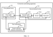
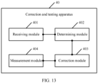
- a second aspect of the embodiments of this application provides a correction and testing apparatus.
- the correction and testing apparatus may include a first phased array, a second phased array, and a test instrument.
- the first phased array is a to-be-tested phased array, and specifically, may be a to-be-tested phased array antenna.
- the second phased array is a mirror array for correction and testing.
- the first phased array includes at least one first RF channel
- the second phased array includes at least one second RF channel.
- a quantity of the second RF channels in the second phased array needs to be greater than or equal to a quantity of the first RF channels, so that each first RF channel can correspond to a second RF channel.
- first RF channel and the second RF channel are coupled face to face.
- a radiation front of the first phased array and a radiation front of the second phased array are spaced by a subwavelength distance.
- An order of magnitude of a subwavelength is nanometer, and therefore the subwavelength is shorter than a wavelength.
- the second phased array in the correction and testing apparatus may receive, through the second RF channel of the second phased array, a coupling signal sent through the first RF channel of the first phased array.
- the test instrument is configured to determine an amplitude value and a phase value of the first RF channel based on the coupling signal, and calculate, based on the amplitude value, the phase value, and standard metering data, an amplitude deviation value and a phase deviation value that correspond to the first RF channel.
- the test instrument is configured to correct amplitude coefficients and phase coefficients that correspond to all first RF channels, and obtain the corrected target amplitude coefficients and the corrected target phase coefficients.
- the test instrument is configured to test the first phased array based on the target amplitude coefficient and the target phase coefficient, and obtain performance indicator parameters corresponding to the first phased array, such as an equivalent isotropically radiated power, an error vector amplitude, and a bit error rate.
- a calibrated mirror phased array and a to-be-tested phased array are disposed face to face by a subwavelength distance, and fast amplitude-phase correction is performed on all RF channels of the to-be-tested phased array by using a face-to-face direct coupling mechanism between antenna array elements, thereby improving test efficiency, reducing a floor area, and lowering costs.
- This can greatly reduce time required for phased array correction and improve test efficiency of a phased array product.
- the first phased array includes a plurality of first RF channels
- the second phased array includes a plurality of second RF channels
- the second phased array further includes a plurality of switches and a plurality of attenuators, where each switch is connected to each second RF channel, and each attenuator is connected to each second RF channel.
- the switches are configured to switch on a target second RF channel in the plurality of second RF channels, where the target second RF channel is any second RF channel in the plurality of second RF channels.
- the second RF channels are configured to receive, through the target second RF channel, a coupling signal sent through a target first RF channel, until coupling signals sent through the plurality of first RF channels are all received, where the target first RF channel is a first RF channel in the plurality of first RF channels that has a mirror symmetry relationship with the target second RF channel.
- Each attenuator is configured to perform signal attenuation processing on the coupling signal.
- the second phased array is mounted on a fixed assembly line test platform as a standard correction and testing device of the first phased array.
- a matrix of switches (a matrix including a plurality of switches) is used to set all second RF channels that are in the second phased array and that are directly coupled to the first RF channels to an off state.
- the matrix of switches performs on-off control on each second RF channel of the second phased array.
- the matrix of switches includes a plurality of switches, and one switch is connected to one second RF channel.
- an attenuator is further provided at each switch, and the attenuator can prevent excessively high power.
- the second RF channels may be switched on one by one in a specific order.
- the first phased array includes nine first RF channels
- the second phased array also includes nine second RF channels
- the second RF channels are sequentially numbered 1 to 9.
- the nine second RF channels are all in an off state.
- the No. 1 second RF channel is first switched on, a coupling signal sent through a No. 1 first RF channel that corresponds to the No. 1 second RF channel is received through the No. 1 second RF channel, and then the No. 1 second RF channel is switched off; next, the No. 2 second RF channel is switched on, and a coupling signal sent through a No. 2 first RF channel that corresponds to the No. 2 second RF channel is received through the No. 2 second RF channel; and the process proceeds until coupling signals from the nine first RF channels are all received.
- the switches and the second RF channels may receive, by performing the following operations, the coupling signal sent through each first RF channels:
- the switches and the second RF channels are configured to separately perform operations of step (1) to step (3) on the plurality of second RF channels having a mirror symmetry relationship with the plurality of first RF channels, until the coupling signals sent through the plurality of first RF channels are all received by the plurality of second RF channels.
- this embodiment of this application describes how the second RF channel receives the coupling signal from the first RF channel. Description is made by using a group of first RF channels and second RF channels corresponding thereto as an example. Amplitude-phase correction and measurement can be performed on the to-be-tested phased array in a one-by-one manner by using a similar method. That is, correction and testing can be performed on each first RF channel. Compared with performing correction and testing on a plurality of RF channels simultaneously, this application helps to improve accuracy of correction and testing.
- the test instrument may include a vector network analysis instrument.
- the vector network analysis instrument is mainly configured to determine, based on the coupling signal, an amplitude value and a phase value that correspond to the first RF channel, and then calculate, based on the amplitude value and a preset amplitude value, the amplitude deviation value corresponding to the first RF channel.
- the vector network analysis instrument is further configured to calculate, based on the phase value and a preset phase value, the phase deviation value corresponding to the first RF channel.
- the vector network analysis instrument may detect, based on the obtained coupling signal, the amplitude value and the phase value that correspond to the first RF channel. It may be understood that usually, the amplitude value and the phase value are specific to each first RF channel. However, in actual application, the amplitude value and the phase value may alternatively be specific to a plurality of first RF channels. Description is made by using an amplitude value and a phase value of a first RF channel as an example. However, this does not constitute a limitation on this solution.
- the amplitude value and the phase value that correspond to the first RF channel are obtained based on the coupling signal, and then the required amplitude deviation value and the required phase deviation value are calculated by using the preset amplitude value and the preset phase value respectively.
- deviation values between the currently measured amplitude and phase values and the preset amplitude and phase values can be obtained, and the deviation values are used to determine whether the RF channel has an exception or a fault, thereby helping to improve applicability and operability of the solution.
- the test instrument includes a test control device.
- the test control device is configured to determine whether an absolute value of the amplitude deviation value falls within a preset amplitude error range, and whether an absolute value of the phase deviation value falls within a preset phase error range. If the two conditions are both satisfied, the test control device may determine that the amplitude deviation value and the phase deviation value satisfy the preset error correction condition.
- the preset amplitude error range is greater than or equal to 10 decibels
- the preset phase error range is greater than or equal to 5 degrees
- amplitude deviation values of nine first RF channels are respectively 12 decibels, 5 decibels, 11 decibels, 10 decibels, 5 decibels, 3 decibels, 7 decibels, 4 decibels, and 19 decibels.
- the largest amplitude deviation value is 19 decibels that is greater than 10 decibels. Therefore, it is determined that the absolute value of the amplitude deviation value falls within the preset amplitude error range.
- Phase deviation values of the nine first RF channels are respectively 3 degrees, 5 degrees, 8 degrees, 1 degree, 1 degree, 3 degrees, 7 degrees, 10 degrees, and 6 degrees. Upon comparison, it is found that the largest phase deviation value is 10 degrees that is greater than 5 degrees. Therefore, it is determined that the absolute value of the phase deviation value falls within the preset phase error range. In this case, it indicates that the preset error correction condition is currently satisfied.
- the preset error correction condition is not satisfied, it is considered that the RF channel has a channel fault, subsequent channel amplitude-phase correction and testing is not performed, and the first phased array is directly disassembled from the second phased array by using a mechanical arm, and returned for corrective maintenance. Therefore, this helps to find whether a fault occurs in the to-be-tested phased array as early as possible, thereby improving applicability of the solution.
- the test instrument is further configured to obtain a first position vector of the first RF channel in a space and a second position vector of the second RF channel in the space; then, the test instrument determines the amplitude coefficient and the phase coefficient based on the first position vector and the second position vector; and finally, the test instrument calculates a coupling coefficient based on a near-field electric field generated by the first RF channel, a near-field electric field generated by the second RF channel, the amplitude coefficient, and the phase coefficient.
- the first position vector and the second position vector may be further obtained, and then, the coupling coefficient is calculated based on a series of parameters. In the foregoing manner, a more accurate coupling coefficient can be obtained and is used in subsequent RF channel correction and testing, thereby improving feasibility of the solution.
- a front of the first phased array and a front of the second phased array may be kept in parallel, and the test instrument is specifically configured to train the amplitude coefficient and the phase coefficient by using a preset relationship model, and then obtain the trained target amplitude coefficient and the trained target phase coefficient, where the preset relationship model is a functional relationship model between the coupling coefficient and a parallel deviation position.
- this embodiment of this application describes how to obtain the target amplitude coefficient and the target phase coefficient when the first phased array and the second phased array are parallel to each other. That is, the obtained amplitude coefficient and the obtained phase coefficient are trained by using the preset relationship model.
- the functional relationship model between the coupling coefficient and the parallel deviation position is set up by using an artificial neural network model, and the amplitude coefficient and the phase coefficient are corrected based on measured data by using an artificial intelligence learning algorithm, to obtain the corresponding target amplitude coefficient and the corresponding target phase coefficient, thereby improving correction precision of each first RF channel.
- the front of the first phased array is not parallel to the front of the second phased array, and then the test instrument is specifically configured to obtain an included angle between the front of the first phased array and the front of the second phased array.
- the test instrument may calculate the target amplitude coefficient based on a first amplitude correction coefficient and the amplitude coefficient, and may calculate the target phase coefficient based on a first phase correction coefficient and the phase coefficient, where the first amplitude correction coefficient represents preset amplitude correction coefficients in different directions (for example, an x-axis, a y-axis, and a z-axis), and the first phase correction coefficient represents preset phase correction coefficients in different directions (for example, an x-axis, a y-axis, and a z-axis).
- the test instrument calculates the target amplitude coefficient based on the first amplitude correction coefficient, a second amplitude correction coefficient, and the amplitude coefficient, and calculates the target phase coefficient based on the first phase correction coefficient, a second phase correction coefficient, and the phase coefficient, where the second amplitude correction coefficient represents an amplitude correction coefficient of coupling between the first RF channel and the corresponding second RF channel, and the second phase correction coefficient represents a phase correction coefficient of coupling between the first RF channel and the corresponding second RF channel.
- this embodiment of this application describes how to obtain the target amplitude coefficient and the target phase coefficient when the first phased array and the second phased array are not parallel to each other. That is, an included angle between the front of the first phased array and the front of the second phased array is obtained first, and a corresponding correction manner is selected based on a type of the included angle. In the foregoing manner, the amplitude coefficient and the phase coefficient are corrected based on measured data by using the amplitude correction coefficient and the phase correction coefficient, to obtain the corresponding target amplitude coefficient and the corresponding target phase coefficient, thereby improving correction precision of each first RF channel.
- the correction and testing apparatus may further perform the following step: The correction and testing apparatus may further determine a beam directivity pattern of the first phased array based on the target amplitude coefficient and the target phase coefficient.
- a beam means a shape formed on the surface of the earth by an electromagnetic wave emitted by a satellite antenna, and mainly includes a global beam, a dot-shaped beam, and a shaped beam. Their shapes depend on a transmit antenna.
- the beam directivity pattern may include a horizontal beam width and a vertical beam width.
- a beam width may mean an included angle between two half-power points of the beam, and is related to an antenna gain. Generally, a higher antenna gain means a narrower beam and a higher search angle resolution.
- the horizontal beam width means an included angle between two directions in which a radiated power is reduced by 3 decibels on both sides of a maximum radiation direction in a horizontal direction.
- the vertical beam width means an included angle between two directions in which a radiated power is reduced by 3 dB on both sides of a maximum radiation direction in a vertical direction.
- a backend processing device of the second phased array can be used to perform online monitoring on the performance indicator parameters of the first phased array, but also the target phase coefficient and the target amplitude coefficient can be used to determine the beam directivity pattern corresponding to the first phased array, to predict the beam directivity pattern of the to-be-tested phased array, thereby improving applicability of the solution.
- test instrument when a transmission amplitude value of the second RF channel is largest, is further configured to determine corresponding positions of the first phased array and the second phased array.
- the test instrument performs a peak search in x-axis and y-axis dimensions, where the x-axis and the y-axis are respectively a horizontal axis and a vertical axis.
- Transmission amplitude values corresponding to the second phased array at different coordinate positions are obtained through the peak search, where the coordinate positions are positions on the x-axis and the y-axis.
- transmission amplitude values of all second RF channels are largest, it may be considered that the front of the first phased array is aligned with the front of the second phased array, and subsequent phased array correction and testing can be continued.
- an embodiment of this application provides a computer device, including: a processor, a memory, a bus, and a communications bus.
- the memory is configured to store computer executable instructions
- the processor is connected to the memory through the bus.
- the server runs, the processor executes the computer executable instructions stored in the memory, so that the server performs the method according to any one of the foregoing aspects.
- an embodiment of this application provides a computer-readable storage medium, configured to store computer software instructions used for the foregoing method.
- the computer software instructions When the computer software instructions are run on a computer, the computer is enabled to perform the method according to any one of the foregoing aspects.
- an embodiment of this application provides a computer program product including instructions.
- the instructions When the instructions are run on a computer, the computer is enabled to perform the method according to any one of the foregoing aspects.
- the phased array correction and testing method is provided.
- the method is mainly applied to the correction and testing apparatus.
- the correction and testing apparatus includes the first phased array and the second phased array.
- the first phased array includes the first radio frequency RF channel
- the second phased array includes the second RF channel
- the first RF channel has a correspondence with the second RF channel
- the radiation front of the second phased array and the radiation front of the first phased array are spaced by the subwavelength distance.
- the correction and testing apparatus receives, through the second RF channel, the coupling signal sent through the first RF channel; and then, determines, based on the coupling signal, the amplitude deviation value and the phase deviation value that correspond to the first RF channel. If the amplitude deviation value and the phase deviation value satisfy the preset error correction condition, the correction and testing apparatus needs to correct the amplitude deviation value and the phase deviation value that correspond to the first RF channel to obtain the target amplitude coefficient and the target phase coefficient. Finally, the correction and testing apparatus may measure the performance indicator parameters of the first phased array by using the target amplitude coefficient and the target phase coefficient.
- a calibrated mirror phased array and a to-be-tested phased array are disposed face to face by a subwavelength distance, and fast amplitude-phase correction is performed on all RF channels of the to-be-tested phased array by using a face-to-face direct coupling mechanism between antenna array elements, thereby improving test efficiency, reducing a floor area, and lowering costs.
- This can greatly reduce time required for phased array correction and improve test efficiency of a phased array product.
- Embodiments of this application provide a phased array correction and testing method and a correction and testing apparatus, to improve test efficiency, reduce a floor area, and lower costs, thereby greatly reducing time required for phased array correction and improving test efficiency of a phased array product.
- a phased array antenna is a most important antenna form in a current satellite mobile communications system, and includes three parts: an antenna array, a feed network, and a beam controller.
- a basic principle is that: after receiving control information including a communication direction, a microprocessor calculates a phase shift of each phase shifter according to an algorithm provided by control software; and then controls, by using an antenna controller, the feed network to complete a phase shifting process. Because phase shifting can compensate for a difference of time at which a same signal arrives at different array elements, in this case, output in-phase superposition of the antenna array reaches a maximum.
- the phased array antenna includes: a phased scanning line antenna array and a planar phased array antenna.
- a phased array is widely applied to fields of fast tracking radars, phase measurement, and the like, and may enable pointing of a main lobe to be adjusted with a requirement of communication.
- An antenna in a shape of a directivity pattern is changed by controlling a feed phase of a radiation unit in an array antenna. Pointing of a maximum value of the directivity pattern of the antenna may be changed by controlling the phase, to implement beam sweeping. In a special case, a level of a side lobe, a minimum value position of the side lobe, and a shape of a whole directivity pattern may also be controlled.
- a feed phase of the phased array antenna is usually controlled by an electronic computer (that is, master control equipment), and the phase changes fast. That is, the pointing of the maximum value of the directivity pattern of the antenna or another parameter changes fast. This is the most significant feature of the phased array antenna.
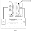
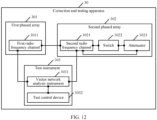
- FIG. 1 is a schematic structural diagram of a correction and testing apparatus according to an embodiment of this application.
- this application provides a correction and testing apparatus based on a mirror direct coupling at a subwavelength spacing.
- the correction and testing apparatus no longer uses any one of a feeder coupling mechanism, a near-field scanning mechanism, and a far-field rotation vector method to perform amplitude-phase correction of a phased array channel, but uses a calibrated mirror phased array.
- the mirror phased array and a to-be-tested phased array are disposed face to face by a subwavelength distance, to implement fast amplitude-phase correction on all channels of the to-be-tested phased array by using a face-to-face direct coupling mechanism between antenna array elements.
- a structure and a function of a mirror array for correction and testing are consistent with a structure and a function of the to-be-tested phased array.
- a matrix of switches controls each RF channel. If switches of all RF channels of the mirror array for correction and testing are simultaneously connected to receive channels, synchronous amplitude-phase correction of all the RF channels can be completed within several seconds.
- the to-be-tested phased array and the mirror array for correction and testing can be accurately spatially docked, assembled, and disassembled by a mechanical arm through a precise positioning hole apparatus that is normatively designed in advance.
- the beam controller in FIG. 1 is configured to control beam pointing and a beam shape of the to-be-tested phased array
- a mirror array controller is configured to control beam pointing and a beam shape of the mirror array for correction and testing.
- a super near-field phased array correction method is used in this application.
- an electromagnetic resonant coupling mechanism is used in this application. That is, amplitude-phase correction of a channel is performed by using information of a direct coupling resonant signal between array elements adjoined face to face, not by measuring near-field, mid-field, or far-field spatial electromagnetic field information with an electromagnetic probe.
- near-field scanning is not required, and a precise electromagnetic probe and an electromagnetic darkroom environment with high costs are not required, either.
- phased array products can be corrected and tested online in batches, so that time required for phased array correction is greatly reduced, and test efficiency of the phased array products is improved.
- This application is particularly suitable for correction and testing of phased array products in a large batch.
- each RF channel and an active device in the RF channel may both be matched based on a test scenario.
- a matching manner of each RF channel in the test scenario is as follows: Assuming that a to-be-tested phased array is a 9-element antenna (that is, including nine RF channels), nine RF channels in a mirror array for correction and testing need to be matched with nine RF channels in the to-be-tested phased array for testing.
- a matching manner of an active device in each RF channel in the test scenario is as follows: If a to-be-tested phased array is in a signal transmit scenario, an output power may be controlled by controlling the active device in the to-be-tested phased array, and the output power may be greater than or equal to 0 dBm. If a mirror array for correction and testing is in a signal receive scenario, an input power may be controlled by adjusting an active device in the mirror array for correction and testing, and the input power may be greater than or equal to -130 dBm and is less than or equal to 0 dBm.
- the active device includes, but is not limited to, a power amplifier, an integrated voltage regulator, a comparator, and a waveform generator. This is not limited herein.
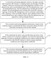
- an embodiment of the phased array correction and testing method in the embodiments of this application includes the following steps.
- a correction and testing apparatus receives, through a second radio frequency RF channel, a coupling signal sent through a first RF channel, where the correction and testing apparatus includes a first phased array and a second phased array, the first phased array is a to-be-tested phased array, the first phased array includes the first RF channel, the second phased array includes the second RF channel, a topology of the first RF channel has a mirror symmetry relationship with a topology of the second RF channel, and a radiation front of the second phased array and a radiation front of the first phased array are spaced by a subwavelength distance.
- the correction and testing apparatus including the first phased array and the second phased array is used.
- the first phased array is a to-be-tested phased array, and specifically, may be a to-be-tested phased array antenna.
- the second phased array is a mirror array for correction and testing.
- the first phased array includes at least one first RF channel
- the second phased array includes at least one second RF channel.
- a quantity of the second RF channels in the second phased array needs to be greater than or equal to a quantity of the first RF channels, so that each first RF channel can correspond to a second RF channel, that is, the first RF channel and the second RF channel are coupled face to face.
- the radiation front of the first phased array and the radiation front of the second phased array are spaced by the subwavelength distance.
- an order of magnitude of a wavelength is micron
- an order of magnitude of the subwavelength is nanometer, and therefore the subwavelength is shorter than the wavelength.
- the topology of the first RF channel has a correspondence with a topology of the second RF channel.
- the topology herein is a hardware structure, including, for example, a spacing between a first RF channel and a second RF channel, the quantity of the first RF channels, and the quantity of the second RF channels. However, the topology does not include a spacing between active devices and a quantity of the active devices.
- an attenuator is deployed on the second RF channel, and an attenuator does not need to be deployed on the first RF channel.
- an amplifier is deployed on the first RF channel, and an amplifier does not need to be deployed on the second RF channel.
- FIG. 3 is a schematic structural diagram of the second phased array according to an embodiment of this application.
- the second phased array includes a 9-element antenna array
- the 9-element antenna array is connected to a power splitter, and energy of one input signal is split by the power splitter into a plurality of signals that are equal or not equal for output.
- energy of a plurality of signals may alternatively be combined into one for output.
- a specific degree of isolation should be ensured between output ports of a power splitter.
- the second phased array is mounted on a fixed assembly line test platform as a standard correction and testing device of the first phased array.
- a matrix of switches performs on-off control on each second RF channel of the second phased array.
- n th second RF channel in the second RF channels is switched on, where n is a positive integer, and n is not greater than the total quantity of the first RF channels.
- the correction and testing apparatus receives, through the n th second RF channel, a coupling signal sent through an n th first RF channel.
- the n th second RF channel herein also has a mirror symmetry relationship with the n th first RF channel.
- the first step to the third step may be used to detect any coupling signal sent through a first RF channel in the first phased array. All the first RF channels in the first phased array may send coupling signals by using the foregoing three steps, until the coupling signals sent through the first RF channels are all received through the second RF channels.
- the first phased array includes nine first RF channels
- the second phased array includes 20 second RF channels.
- the 20 second RF channels are sequentially numbered 1 to 20.
- second RF channels having a mirror symmetry relationship with the first RF channels are sequentially numbered 1 to 9.
- the nine second RF channels are all in an off state.
- the No. 1 second RF channel is first switched on, a coupling signal sent through the No. 1 first RF channel that corresponds to the No. 1 second RF channel is received through the No. 1 second RF channel, and then the No. 1 second RF channel is switched off; next, the No. 2 second RF channel is switched on, a coupling signal sent through the No. 2 first RF channel that corresponds to the No. 2 second RF channel is received through the No. 2 second RF channel; and the process proceeds until coupling signals from the nine first RF channels are all received.
- the second RF channel may not receive coupling signals in a fixed order.
- the correction and testing apparatus determines, based on the coupling signal, an amplitude deviation value and a phase deviation value that correspond to the first RF channel.
- the correction and testing apparatus first determines, based on the coupling signal transmitted from the first phased array, an amplitude value and a phase value that correspond to each first RF channel; and then calculates, based on standard metering data, an amplitude deviation value and a phase deviation value that correspond to the first RF channel.
- a radome front of the second phased array is used as a phase reference plane
- standard metering data corresponding to each second RF channel of the second phased array is used as a measurement reference
- a multi-RF channel vector network analyzer is used to perform amplitude-phase measurement on a channel of the first phased array.
- the matrix of switches performs on-off switching on the switches of the second RF channels in the second phased array sequentially based on numbers of the second RF channels, to perform amplitude-phase measurement and correction on the first RF channels of the first phased array one by one.
- the matrix of switches sets the switches of all the second RF channels in the second phased array to a channel receiving state, and then, synchronously measures and records all signals coupled through the first RF channels.
- ⁇ ⁇ i represents the amplitude deviation value of the i th first RF channel
- ⁇ ⁇ represents the phase deviation value of the i th first RF channel
- an amplitude value ⁇ k of a coupling signal from a k th first RF channel is far greater than or less than its corresponding unit measurement data a k ref , that is, a k ⁇ a k ref or a k ⁇ a k ref , it is determined that the k th first RF channel in the first phased array has an exception or a channel fault, and channel amplitude-phase correction is not performed subsequently.
- a phase value ⁇ k of a coupling signal from a k th first RF channel is far greater than or less than its corresponding unit measurement data ⁇ k ref , that is, ⁇ k ⁇ ⁇ k ref or ⁇ k ⁇ ⁇ k ref , it is determined that the k th first RF channel in the first phased array has an exception or a channel fault, and channel amplitude-phase correction is not performed subsequently.
- k is any integer ranging from 1 to N .
- the correction and testing apparatus corrects an amplitude coefficient and a phase coefficient that correspond to the first RF channel to obtain a target amplitude coefficient and a target phase coefficient.
- the amplitude deviation value and the phase deviation value after the amplitude deviation value and the phase deviation value are obtained, whether an absolute value of the amplitude deviation value falls within a preset amplitude error range, and whether an absolute value of the phase deviation value falls within a preset phase error range need to be determined. If the two conditions are both satisfied, it is determined that the amplitude deviation value and the phase deviation value satisfy the preset error correction condition. That is, the amplitude coefficient and the phase coefficient that correspond to the first RF channel need to be corrected until the corrected amplitude deviation value and the corrected phase deviation value satisfy the preset error correction condition, and the corrected target amplitude coefficient and the corrected target phase coefficient are obtained.
- the absolute value of the amplitude deviation value does not fall within the preset amplitude error range or the absolute value of the phase deviation value does not fall within the preset phase error range, it indicates that the amplitude coefficient and the phase coefficient do not need to be corrected.
- amplitude and phase thresholds that is, an amplitude threshold ⁇ th and a phase threshold ⁇ th may be preset, and then an amplitude deviation value ⁇ ⁇ i and a phase deviation value ⁇ ⁇ i of each first RF channel are determined respectively based on ⁇ th and ⁇ th .
- the amplitude coefficient and the phase coefficient that correspond to the first RF channel need to be corrected until a maximum amplitude deviation value of each first RF channel on a reference plane of the second phased array is less than the preset amplitude threshold ⁇ th , and a maximum phase deviation value is less than the preset phase threshold ⁇ th .
- the amplitude threshold ⁇ th and the phase threshold ⁇ th may be set based on an actual situation.
- the amplitude threshold ⁇ th may be set to -10 decibels (decibel, dB) or below, and the phase threshold ⁇ th may be set to 10° or below.
- the amplitude threshold ⁇ th may be set to -20 dB or below, and the phase threshold ⁇ th may be set to 1° or below.
- the amplitude threshold ⁇ th and the phase threshold ⁇ th may be alternatively set according to a requirement. Only an example is provided herein, and should not be understood as a limitation on this application.
- the correction and testing apparatus measures performance indicator parameters of the first phased array by using the target amplitude coefficient and the target phase coefficient.
- target amplitude coefficients and target phase coefficients that correspond to the first RF channels can be obtained.
- a backend processing device of the second phased array can be used to perform online monitoring on the performance indicator parameters of the first phased array.
- the performance indicator parameters include, but are not limited to, an equivalent isotropically radiated power (effective isotropic radiated power, ERIP), an error vector amplitude (error vector magnitude, EVM), and a bit error rate (bit error rate, BER).
- the correction and testing apparatus may further determine a beam directivity pattern of the first phased array based on the target amplitude coefficient and the target phase coefficient.
- F array ( ⁇ , ⁇ ) represents the directivity pattern of a synthesized beam of the first phased array
- a element ( ⁇ , ⁇ ) represents an element directivity pattern in the first phased array
- ⁇ i represents a target amplitude coefficient of a coupling signal corresponding to an i th first RF channel that has been corrected in the first phased array
- ⁇ i represents a target phase coefficient of a coupling signal corresponding to the i th first RF channel that has been corrected in the first phased array
- k represents a free space wave vector
- r i represents a position vector of the i th first RF channel in the first phased array.
- the phased array correction and testing method is provided.
- the method is mainly applied to the correction and testing apparatus.
- the correction and testing apparatus includes the first phased array and the second phased array.
- the first phased array includes the first radio frequency RF channel
- the second phased array includes the second RF channel
- the first RF channel has a correspondence with the second RF channel
- the radiation front of the second phased array and the radiation front of the first phased array are spaced by the subwavelength distance.
- the correction and testing apparatus receives, through the second RF channel, the coupling signal sent through the first RF channel; and then, determines, based on the coupling signal, the amplitude deviation value and the phase deviation value that correspond to the first RF channel.
- the correction and testing apparatus needs to correct the amplitude coefficient and the phase coefficient that correspond to the first RF channel to obtain the target amplitude coefficient and the target phase coefficient.
- the correction and testing apparatus may measure the performance indicator parameters of the first phased array by using the target amplitude coefficient and the target phase coefficient.
- a calibrated mirror phased array and a to-be-tested phased array are disposed face to face by a subwavelength distance, and fast amplitude-phase correction is performed on all RF channels of the to-be-tested phased array by using a face-to-face direct coupling mechanism between antenna array elements, thereby improving test efficiency, reducing a floor area, and lowering costs.
- the method may further include:
- the correction and testing apparatus obtains the first position vector of the first RF channel in the space and the second position vector of the second RF channel in the space; and then calculates the amplitude coefficient and the phase coefficient based on the first position vector and the second position vector, where the amplitude coefficient and the phase coefficient are to-be-corrected parameters. Finally, the correction and testing apparatus calculates the coupling coefficient based on the near-field electric field generated by the first RF channel, the near-field electric field generated by the second RF channel, the amplitude coefficient, and the phase coefficient.
- an amplitude coefficient and a phase coefficient of each first RF channel in the first phased array may be corrected. It may be understood that before correction, it is necessary to determine that an amplitude deviation value corresponding to the amplitude coefficient and a phase deviation value corresponding to the phase coefficient satisfy the preset error correction condition.
- the first RF channels of the first phased array are corrected by using a formula for calculating channel direct coupling compensation, Monte Carlo probability statistical estimation, and an iterative least square algorithm.
- C ii represents a coupling coefficient
- E i DUT r r i DUT represents a near-field electric field generated by an i th first RF channel in the first phased array
- E i Im ag r r i Im ag represents a near-field electric field generated by an i th second RF channel in the second phased array
- r i DUT represents a first position vector of the i th first RF channel in the first phased array in a space
- r i Im ag represents a second position vector of the i th second RF channel in the second phased array in the space
- ⁇ ii r i DUT r i Im ag represents an amplitude coefficient between the i th first RF channel and the i th second RF channel
- ⁇ ii r i DUT r i Im ag represents a phase coefficient between the i th first RF channel and the i th second
- FIG. 4 is a schematic diagram of the fronts of the first phased array and the second phased array according to an embodiment of this application. There may be an included angle between the front of the first phased array and the front of the second phased array. The following describes how to calculate the target amplitude coefficient and the target phase coefficient in cases of different included angles and in cases in which the fronts are parallel or not parallel.
- Case 1 The front of the first phased array is parallel to the front of the second phased array.
- FIG. 5 is a schematic diagram of an embodiment in which the front of the first phased array is parallel to the front of the second phased array according to an embodiment of this application.
- the front of the first phased array is totally parallel to the front of the second phased array, no axial deviation exists, centers of elements are aligned with each other, and all directly coupled RF channels have an equal spacing therebetween.
- a backhaul three-layered artificial neural network model is used.
- a relationship model of an x direction and a coupling coefficient C ii , a relationship model of a y direction and the coupling coefficient C ii , and a relationship model of an xy-direction parallel deviation position ( ⁇ x , ⁇ y ) and the coupling coefficient C ii are established, and the three relationship models may be generally referred to as a preset relationship model.
- an amplitude coefficient ⁇ ii r i DUT r i Im ag and a phase coefficient ⁇ ii r i DUT r i Im ag are corrected by using an artificial intelligence learning algorithm and a Monte Carlo probability prediction method, to improve correction precision of an element channel and obtain the corrected target amplitude coefficient and the corrected target phase coefficient.
- Case 2 The front of the first phased array is not parallel to the front of the second phased array.
- FIG. 6 is a schematic diagram of an embodiment in which the front of first phased array is not parallel to the front of the second phased array according to an embodiment of this application. Because of factors such as an actual machining error, an assembly error of each array element antenna, a positioning error of spatial matching, and a device deformation error caused by a structural stress, the first RF channels of the first phased array are not neatly arranged, and the front of the first phased array is not strictly parallel to the front of the second phased array. First, a main axis of the first phased array is not parallel to that of the second phased array in a space, to form a specific included angle.
- a small included angle may be 10 degrees, 15 degrees, or 20 degrees, and a large included angle may be 45 degrees, 50 degrees, or 60 degrees.
- the small included angle and the large included angle may be defined based on a case. This is not limited herein.
- Coordinate rotation transformation and a near-field coupling matrix analysis method are used to correct a coupling coefficient (which includes direct coupling and mutual coupling between RF channels) of a small-angle deviation and a coupling coefficient (which includes direct coupling and mutual coupling between RF channels) of a large-angle deviation.
- the target amplitude coefficient is calculated based on a first amplitude correction coefficient and the amplitude coefficient
- the target phase coefficient is calculated based on a first phase correction coefficient and the phase coefficient, where the first amplitude correction coefficient represents preset amplitude correction coefficients in different directions, and the first phase correction coefficient represents preset phase correction coefficients in different directions.
- ⁇ ii ′ r i DUT r i Im ag represents a target phase coefficient
- ⁇ ii x represents a first phase correction coefficient in an x-axis direction
- ⁇ ii y represents a first phase correction coefficient in a y-axis direction
- ⁇ ii z represents a first phase correction coefficient in a main axis in a z-axis direction
- ⁇ ii r i DUT r i Im ag represents a phase coefficient.
- the target amplitude coefficient is calculated based on the first amplitude correction coefficient, a second amplitude correction coefficient, and the amplitude coefficient
- the target phase coefficient is calculated based on the first phase correction coefficient, a second phase correction coefficient, and the phase coefficient, where the second amplitude correction coefficient represents an amplitude correction coefficient of coupling between RF channels, and the second phase correction coefficient represents a phase correction coefficient of coupling between the RF channels.
- ⁇ ii ′′ r i DUT r i Im ag represents a target amplitude coefficient
- ⁇ ii x represents a first phase correction coefficient in an x-axis direction
- ⁇ ii y represents a first phase correction coefficient in a y-axis direction
- ⁇ ii z represents a first phase correction coefficient in a main axis in a z-axis direction
- ⁇ il represents a second phase correction coefficient caused by proximity coupling between an i th first RF channel and an i th second RF channel
- ⁇ ii r i DUT r i Im ag represents a phase coefficient.
- Parameter correction setting of the first RF channels is performed by using adjustable attenuators and phase shifters of the first phased array.
- a standard second phased array controlled by a plurality of channel switches is constructed, a face-to-face direct coupling technology is used, information of the first RF channels of the first phased array are collected successively, and amplitude-phase correction of the first RF channels of the first phased array, channel fault or failure detection, and performance indicator parameter measurement and calculation are implemented at a subwavelength spacing.
- the phased array antenna can be corrected and tested effectively, and the foregoing manner achieves good stability, facilitates maintenance, and is suitable for testing of products in batches on an assembly line, thereby improving applicability and operability of the solution.
- the method may further include: when a transmission amplitude value of the second RF channel is largest, determining corresponding positions of the first phased array and the second phased array.
- the correction and testing apparatus before the correction and testing apparatus receives, through the second RF channel, the coupling signal sent through the first RF channel, the first phased array needs to be aligned with the second phased array.
- the correction and testing apparatus performs a peak search in x-axis and y-axis dimensions, where the x-axis and the y-axis are respectively a horizontal axis and a vertical axis.
- Transmission amplitude values corresponding to the second phased array at different coordinate positions are obtained through the peak search, where the coordinate positions are positions on the x-axis and the y-axis.
- a root mean square (root mean square, RMS) of transmission amplitude values of all second RF channels is a maximum value, it may be considered that the front of the first phased array is aligned with the front of the second phased array, and subsequent correction and testing on the phased array can be continued.
- positions of the first phased array and the second phased array further need to be adjusted, and when the positions are adjusted to optimal positions, the transmission amplitude value of the second RF channel should be largest.
- optimal position points of the first phased array and the second phased array can be found by using a physical position search method, and correction and testing is performed based on the optimal position points, thereby achieving a more accurate and efficient correction and testing effect.
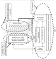
- FIG. 7 is a schematic functional diagram of a correction and testing apparatus in an application scenario according to this application. As shown in the figure, a positioning hole of a to-be-tested phased array (the first phased array) is aligned with a positioning mark of a mirror array for correction and testing (the second phased array) through a mechanical arm, for spatial assembly of the to-be-tested phased array.
- a spacing between a radome of the to-be-tested phased array and a radome of the mirror array for correction and testing is d 0 , d 0 is fixed by a dowel pin device at a subwavelength level, that is, shorter than 1/5 central operating wavelength.
- a spacing between the to-be-tested phased array and the mirror array for correction and testing is d
- a distance between the to-be-tested phased array and the radome of the to-be-tested phased array is d 1
- the spacing between the radome of the to-be-tested phased array and the radome of the mirror array for correction and testing is d 0
- a distance between the mirror array for correction and testing and array radome of the mirror correction and testing is d 2 .
- the radome 1 covers the to-be-tested phased array.
- the 9-element antenna of the mirror array for correction and testing is connected to nine same single pole single throw switches respectively, and then connected to a power splitter.
- the standard second phased array controlled by the plurality of channel switches uses the face-to-face direct coupling technology to implement amplitude-phase correction of the channels of the first phased array, channel fault or failure detection, and performance indicator parameter measurement and calculation at the subwavelength spacing.
- a relationship model between a position deviation x and a coupling coefficient r and a relationship model between a position deviation y and the coupling coefficient r are separately set up, to improve coupling coefficient calculation precision.
- Parameter correction setting of the first RF channels is performed by using adjustable attenuators and phase shifters of the first phased array.
- FIG. 8 is a schematic flowchart of the phased array correction and testing method in an application scenario according to this application.
- a setup for correcting and testing a phased array needs to be prepared first, that is, a test environment is set up, including one mirror array for correction and testing (the second phased array) whose quantity of channel elements is greater than or equal to that of a to-be-tested phased array (the first phased array).
- the mirror array for correction and testing is calibrated by using a national standard-compliant metering device, and is mounted on an assembly line test platform.
- step 202 amplitude data and phase data of RF channels of a to-be-tested phased array are collected. Specifically, during assembly line testing, a mechanical arm mounts the to-be-tested phased array by using a positioning hole, and then, the amplitude data and the phase data of the RF channels of the to-be-tested phased array are collected at a subwavelength spacing by using the face-to-face direct coupling technology.
- step 203 the amplitude data and the phase data of the RF channels of the to-be-tested phased array are corrected.
- step 204 after the to-be-tested phased array is corrected, performance indicator parameters of the to-be-tested phased array may be further measured, where the performance indicator parameters include a transmit performance indicator, a receive performance indicator, and the like.
- step 205 the collected test data is determined and analyzed; and if the amplitude data and the phase data are abnormal (all or some of the amplitude data and the phase data exceeds thresholds), the process goes back to step 202; or if the amplitude data and the phase data are both normal, step 206 is performed.
- step 206 a test result is output, and the test is complete.
- the tested phased array can be disassembled by using a mechanical arm, and then, correction and testing of a next to-be-tested phased array start, that is, step 201 to step 205 are repeated.
- a correction and testing apparatus 30 in an embodiment of this application includes a first phased array 301, a second phased array 302, and a test instrument 303, where the first phased array 301 is a to-be-tested phased array, the first phased array 301 includes a first RF channel 3011, the second phased array 302 includes a second RF channel 3021, a topology of the first RF channel 3011 has a mirror symmetry relationship with a topology of the second RF channel 3021, and a radiation front of the second phased array 302 and a radiation front of the first phased array 301 are spaced by a subwavelength distance.
- the correction and testing apparatus 30 includes:
- the second phased array 302 is configured to receive, through the second RF channel 3021, a coupling signal sent by the first phased array 301 through the first RF channel 3011.
- the test instrument 303 is configured to determine, based on the coupling signal, an amplitude deviation value and a phase deviation value that correspond to the first RF channel 3011.
- the test instrument 303 is configured to correct an amplitude coefficient and a phase coefficient that correspond to the first RF channel 3011 to obtain a target amplitude coefficient and a target phase coefficient.
- the test instrument 303 is configured to measure performance indicator parameters of the first phased array 3011 by using the target amplitude coefficient and the target phase coefficient.
- a positioning hole of the first phased array 301 is aligned with a positioning mark of the second phased array 302 through a mechanical arm, for spatial assembly of the first phased array 301.
- an alignment manner may be laser alignment or dowel pin positioning, or may be another alignment manner. This is not limited herein.
- a spacing between a radome of the first phased array 301 and a radome of the second phased array 302 is d 0 , where d 0 is less than a wavelength.
- a spacing between the first phased array 301 and the second phased array 302 is d
- a distance between the first phased array 301 and the radome of the first phased array 301 is d 1
- the spacing between the radome of the second phased array 302 and the radome of the first phased array 301 is d 0
- a distance between the second phased array 302 and the radome of the second phased array 302 is d 2
- d d 1 +d 0 +d 2 .
- test instrument 303 may determine corresponding positions of the first phased array 301 and the second phased array 302.
- the correction and testing apparatus 30 first determines, based on the coupling signal transmitted from the first phased array 301, an amplitude value and a phase value that correspond to each first RF channel 3011, and then calculates, based on standard metering data, an amplitude deviation value and a phase deviation value that correspond to the first RF channel 3011. After the amplitude deviation value and the phase deviation value are obtained, the correction and testing apparatus 30 needs to determine whether an absolute value of the amplitude deviation value falls within a preset amplitude error range, and whether an absolute value of the phase deviation value falls within a preset phase error range.
- the amplitude deviation value and the phase deviation value satisfy the preset error correction condition, that is, an amplitude coefficient and a phase coefficient that correspond to the first RF channel 3011 need to be corrected until the corrected amplitude deviation value and the corrected phase deviation value satisfy the preset error correction condition, and the corrected target amplitude coefficient and the corrected target phase coefficient are obtained. Otherwise, if the absolute value of the amplitude deviation value does not fall within the preset amplitude error range or the absolute value of the phase deviation value does not fall within the preset phase error range, it indicates that the amplitude coefficient and the phase coefficient do not need to be corrected.
- correction and testing apparatus 30 corrects amplitude coefficients and phase coefficients that correspond to all first RF channels 3011, target amplitude coefficients and target phase coefficients that correspond to the first RF channels 3011 can be obtained.
- the correction and testing apparatus 30 may further determine a beam directivity pattern of the first phased array 301 based on the target amplitude coefficients and the target phase coefficients.
- the correction and testing apparatus is provided.
- a calibrated mirror phased array and a to-be-tested phased array are disposed face to face by a subwavelength distance, and fast amplitude-phase correction is performed on all RF channels of the to-be-tested phased array by using a face-to-face direct coupling mechanism between antenna array elements, thereby improving test efficiency, reducing a floor area, and lowering costs.
- This can greatly reduce time required for phased array correction and improve test efficiency of a phased array product.
- the first phased array 301 includes a plurality of first RF channels 3011
- the second phased array 302 includes a plurality of second RF channels 3021
- the second phased array 302 further includes a plurality of switches 3022 and a plurality of attenuators 3023.
- Each switch 3022 is connected to each second RF channel 3021
- each attenuator 3023 is connected to each second RF channel 3021.
- the switches 3022 are configured to switch off the plurality of second RF channels 3021.
- the switches 3022 are configured to switch on a target second RF channel in the plurality of second RF channels 3021, where the target second RF channel is any second RF channel 3021 in the plurality of second RF channels 3021.
- the second RF channels 3021 are configured to receive, through the target second RF channel, a coupling signal sent through a target first RF channel, until coupling signals sent through the plurality of first RF channels 3011 are all received, where the target first RF channel is a first RF channel 3011 in the plurality of first RF channels 3011 that has a mirror symmetry relationship with the target second RF channel.
- Each attenuator 3023 is configured to perform signal attenuation processing on the coupling signal.
- the switches 3022 are specifically configured to: when the plurality of second RF channels 3021 are in the off state, switch on an n th second RF channel 3021 in the plurality of second RF channels 3021, where n is a positive integer.
- the second RF channels 3021 are specifically configured to receive, through the n th second RF channel 3021, a coupling signal sent through an n th first RF channel 3011, where the n th second RF channel 3021 has a mirror symmetry relationship with the n th first RF channel 3011.
- the switch 3022 is specifically configured to switch off the n th second RF channel 3021.
- the switches 3022 and the second RF channels 3021 are configured to separately perform operations of step (1) to step (3) on the plurality of second RF channels 3021 having a mirror symmetry relationship with the plurality of first RF channels 3011, until the coupling signals sent through the plurality of first RF channels 3011 are all received by the plurality of second RF channels.
- the second phased array 302 is mounted on a fixed assembly line test platform as a standard correction and testing device of the first phased array 301.
- a matrix of the switches 3022 performs on-off control on each second RF channel 3021 of the second phased array 302. First, all the second RF channels 3021 are switched off; then, the second RF channels 3021 are sequentially switched on; and further, the coupling signals sent through the first RF channels 3011 are received through the second RF channels 3021 to perform amplitude-phase correction of channels one by one or selectively. If all first RF channels 3011 need to be synchronously corrected, it only needs to set the second RF channels 3021 to a receiving state by using all the switches 3022.
- each second RF channel 3021 is connected to a separate switch 3022 and a separate attenuator 3023 separately, and then is connected to a power splitter.
- the switch 3022 may be a single pole single throw (single pole single throw, SPST) switch, where the SPST is a type of coaxial switch.
- the switch 3022 may alternatively be a single pole double throw (single pole double throw, SPDT) switch, a double pole double throw (double pole double throw, DPDT) switch, a single pole six throw (single pole six throw, SP6T) switch, or the like. Only an example is provided herein, and should not be understood as a limitation on this solution.
- the attenuator 3023 can protect a circuit, and can further adjust strength of a signal in the circuit, and in a comparative measurement circuit, can be used to directly read an attenuation value of a to-be-tested network and improve impedance matching. If some circuits require a relatively stable load impedance, an attenuator may be inserted between the circuit and an actual load impedance to mitigate an impedance change.
- the test instrument 303 includes a vector network analysis instrument 3031.
- the vector network analysis instrument 3031 is configured to obtain, based on a coupling signal, an amplitude value and a phase value that correspond to a first RF channel 3011.
- the vector network analysis instrument 3031 is configured to calculate, based on the amplitude value and a preset amplitude value, the amplitude deviation value corresponding to the first RF channel 3011.
- the vector network analysis instrument 3031 is configured to calculate, based on the phase value and a preset phase value, the phase deviation value corresponding to the first RF channel 3011.
- the vector network analysis instrument 3031 is a device for testing electromagnetic wave energy.
- the vector network analysis instrument 3031 not only can measure various parameter amplitude values of a one-port network or a two-port network, but also can measure a phase value.
- the matrix of switches 3022 performs on-off switching on the switches of the second RF channels 3021 in the second phased array 302 sequentially based on numbers of the second RF channels 3021, to perform amplitude-phase measurement and correction on the first RF channels 3011 of the first phased array 301 one by one.
- the matrix of switches 3022 sets the switches of all the second RF channels 3021 in the second phased array 302 to a channel receiving state, and then, synchronously measures and records all signals coupled through the first RF channels 3011.
- ⁇ a i represents the amplitude deviation value of the i th first RF channel 3011
- ⁇ ⁇ represents the phase deviation value of the i th first RF channel 3011.
- the amplitude value and the phase value that correspond to the first RF channel are obtained based on the coupling signal, and then the required amplitude deviation value and the required phase deviation value are calculated by using the preset amplitude value and the preset phase value respectively.
- deviation values between the currently measured amplitude and phase values and the preset amplitude and phase values can be obtained, and the deviation values are used to determine whether the RF channel has an exception or a fault, thereby helping to improve applicability and operability of the solution.
- the test instrument can effectively correct a position deviation caused by machining, channel assembly, test of matching assembly, and structural deformation, helping to improve feasibility of the solution.
- the test instrument 303 includes a test control device 3032.
- the test control device 3032 is configured to determine whether an absolute value of the amplitude deviation value falls within a preset amplitude error range, and whether an absolute value of the phase deviation value falls within a preset phase error range.
- test control device 3022 is configured to determine that the amplitude deviation value and the phase deviation value satisfy the preset error correction condition.
- the test control device 3032 needs to determine whether the absolute value of the amplitude deviation value falls within the preset amplitude error range, and whether the absolute value of the phase deviation value falls within the preset phase error range. If the two conditions are both satisfied, the test control device 3032 determines that the amplitude deviation value and the phase deviation value satisfy the preset error correction condition. That is, the amplitude coefficient and the phase coefficient that correspond to the first RF channel 3011 need to be corrected until the corrected amplitude deviation value and the corrected phase deviation value satisfy the preset error correction condition, and the corrected target amplitude coefficient and the corrected target phase coefficient are obtained.
- the absolute value of the amplitude deviation value does not fall within the preset amplitude error range or the absolute value of the phase deviation value does not fall within the preset phase error range, it indicates that the amplitude coefficient and the phase coefficient do not need to be corrected.
- test instrument 303 may alternatively obtain a first position vector of the first RF channel 3011 in a space and a second position vector of the second RF channel 3021 in the space, and then, determine the amplitude coefficient and the phase coefficient based on the first position vector and the second position vector.
- the test instrument 303 calculates a coupling coefficient based on a near-field electric field generated by the first RF channel 3011, a near-field electric field generated by the second RF channel 3021, the amplitude coefficient, and the phase coefficient.
- the test instrument 303 trains the amplitude coefficient and the phase coefficient by using a preset relationship model.
- the test instrument 303 is specifically configured to obtain the trained target amplitude coefficient and the trained target phase coefficient, where the preset relationship model is a functional relationship model between the coupling coefficient and a parallel deviation position.
- the test instrument 303 first obtains an included angle between the front of the first phased array 301 and the front of the second phased array 302. If the included angle is a small included angle, the test instrument 303 calculates the target amplitude coefficient based on a first amplitude correction coefficient and the amplitude coefficient, and calculates the target phase coefficient based on a first phase correction coefficient and the phase coefficient, where the first amplitude correction coefficient represents preset amplitude correction coefficients in different directions, and the first phase correction coefficient represents preset phase correction coefficients in different directions.
- the test instrument 303 is specifically configured to calculate the target amplitude coefficient based on the first amplitude correction coefficient, a second amplitude correction coefficient, and the amplitude coefficient, and calculate the target phase coefficient based on the first phase correction coefficient, a second phase correction coefficient, and the phase coefficient, where the second amplitude correction coefficient represents an amplitude correction coefficient of coupling between RF channels, and the second phase correction coefficient represents a phase correction coefficient of coupling between the RF channels.
- test instrument 303 may further determine a beam directivity pattern of the first phased array 301 based on the target amplitude coefficient and the target phase coefficient.
- functions of the vector network analysis instrument 3031 and functions of the test control device 3022 may be integrated on one device, for example, are all integrated on the vector network analysis instrument 3031 or are all integrated on the test control device 3022, and in an actual application, may be alternatively integrated on another module of the test instrument 303. This is not limited herein.
- the obtained amplitude coefficient and the obtained phase coefficient are trained by using the preset relationship model.
- an included angle between the front of the first phased array and the front of the second phased array is obtained first, and a corresponding correction manner is selected based on a type of the included angle.
- the amplitude coefficient and the phase coefficient are corrected based on measured data, to obtain the corresponding target amplitude coefficient and the corresponding target phase coefficient, to improve correction precision of each first RF channel.
- a correction and testing apparatus 40 in this embodiment of this application includes a first phased array and a second phased array, where the first phased array is a to-be-tested phased array, the first phased array includes a first RF channel, the second phased array includes a second RF channel, a topology of the first RF channel has a mirror symmetry relationship with a topology of the second RF channel, and a radiation front of the second phased array and a radiation front of the first phased array are spaced by a subwavelength distance.
- the correction and testing apparatus 40 includes:
- the correction and testing apparatus 40 includes the first phased array and the second phased array.
- the first phased array is a to-be-tested phased array
- the first phased array includes the first RF channel
- the second phased array includes the second RF channel
- the first RF channel has a correspondence with the second RF channel
- the radiation front of the second phased array and the radiation front of the first phased array are spaced by the subwavelength distance.
- the receiving module 401 receives, through the second RF channel, the coupling signal sent through the first RF channel.
- the determining module 402 determines, based on the coupling signal received by the receiving module 401, the amplitude deviation value and the phase deviation value that correspond to the first RF channel.
- the correction module 403 corrects the amplitude coefficient and the phase coefficient that correspond to the first RF channel to obtain the target amplitude coefficient and the target phase coefficient.
- the measurement module 404 measures the performance indicator parameters of the first phased array by using the target amplitude coefficient and the target phase coefficient corrected by the correction module 403.
- the correction and testing apparatus is provided.
- a calibrated mirror phased array and a to-be-tested phased array are disposed face to face by a subwavelength distance, and fast amplitude-phase correction is performed on all RF channels of the to-be-tested phased array by using a face-to-face direct coupling mechanism between antenna array elements, thereby improving test efficiency, reducing a floor area, and lowering costs.
- This can greatly reduce time required for phased array correction and improve test efficiency of a phased array product.
- the first phased array includes a plurality of first RF channels
- the second phased array includes a plurality of second RF channels.
- the receiving module 401 is specifically configured to: switch off the plurality of second RF channels;
- the amplitude value and the phase value that correspond to the first RF channel are obtained based on the coupling signal, and then the required amplitude deviation value and the required phase deviation value are calculated by using the preset amplitude value and the preset phase value respectively.
- deviation values between the currently measured amplitude and phase values and the preset amplitude and phase values can be obtained, and the deviation values are used to determine whether the RF channel has an exception or a fault, thereby helping to improve applicability and operability of the solution.
- the correction and testing apparatus 40 further includes:
- the preset error correction condition is not satisfied, it is considered that the RF channel has a channel fault, subsequent channel amplitude-phase correction and testing is not performed, and the first phased array is directly disassembled from the second phased array by using a mechanical arm, and returned for corrective maintenance. Therefore, this helps to find whether a fault occurs in the to-be-tested phased array as early as possible, thereby improving applicability of the solution.
- the correction and testing apparatus 40 further includes:
- the first position vector and the second position vector may be further obtained, and then, the coupling coefficient is calculated based on a series of parameters. In the foregoing manner, a more accurate coupling coefficient can be obtained and is used in subsequent RF channel correction and testing, thereby improving feasibility of the solution.
- the correction and testing apparatus 40 further includes:
- this embodiment of this application describes how to obtain the target amplitude coefficient and the target phase coefficient when the first phased array and the second phased array are parallel to each other, that is, training the obtained amplitude coefficient and the obtained phase coefficient by using the preset relationship model.
- the functional relationship model between the coupling coefficient and the parallel deviation position is set up by using an artificial neural network model, and the amplitude coefficient and the phase coefficient are corrected based on measured data by using an artificial intelligence learning algorithm, to obtain the corresponding target amplitude coefficient and the corresponding target phase coefficient, thereby improving correction precision of each first RF channel.
- the correction and testing apparatus 40 further includes:
- this embodiment of this application describes how to obtain the target amplitude coefficient and the target phase coefficient when the first phased array and the second phased array are not parallel to each other. That is, an included angle between the front of the first phased array and the front of the second phased array is obtained first, and a corresponding correction manner is selected based on a type of the included angle.
- the amplitude coefficient and the phase coefficient are corrected based on measured data by using the amplitude correction coefficient and the phase correction coefficient, to obtain the corresponding target amplitude coefficient and the corresponding target phase coefficient, thereby improving correction precision of each first RF channel.
- the correction and testing apparatus 40 further includes: the determining module 402 is further configured to determine a beam directivity pattern of the first phased array based on the target amplitude coefficient and the target phase coefficient after the correction module 403 obtains the target amplitude coefficient and the target phase coefficient.
- a backend processing device of the second phased array can be used to perform online monitoring on the performance indicator parameters of the first phased array, but also the target phase coefficient and the target amplitude coefficient can be used to determine the beam directivity pattern corresponding to the first phased array, to predict the beam directivity pattern of the to-be-tested phased array, thereby improving applicability of the solution.
- the determining module 402 is further configured to: before the receiving module 401 receives, through the second RF channel, the coupling signal sent through the first RF channel, when a transmission amplitude value of the second RF channel is largest, determine corresponding positions of the first phased array and the second phased array.
- positions of the first phased array and the second phased array need to be adjusted, and when the positions are adjusted to optimal positions, the transmission amplitude value of the second RF channel should be largest.
- optimal position points of the first phased array and the second phased array can be found by using a physical position search method, and correction and testing is performed based on the optimal position points, thereby achieving a more accurate and efficient correction and testing effect.
- All or some of the foregoing embodiments may be implemented by using software, hardware, firmware, or any combination thereof.
- the embodiments may be implemented completely or partially in a form of a computer program product.
- the computer program product includes one or more computer instructions. When the computer program instructions are loaded and executed on the computer, the procedure or functions according to the embodiments of the present invention are all or partially generated.
- the computer may be a general-purpose computer, a dedicated computer, a computer network, or other programmable apparatuses.
- the computer instructions may be stored in a computer-readable storage medium or may be transmitted from a computer-readable storage medium to another computer-readable storage medium.
- the computer instructions may be transmitted from a website, computer, server, or data center to another website, computer, server, or data center in a wired (for example, a coaxial cable, an optical fiber, or a digital subscriber line (digital subscriber line, DSL)) or wireless (for example, infrared, radio, and microwave, or the like) manner.
- the computer-readable storage medium may be any usable medium accessible by a computer, or a data storage device, such as a server or a data center, integrating one or more usable media.
- the usable medium may be a magnetic medium (for example, a floppy disk, a hard disk, or a magnetic tape), an optical medium (for example, a DVD), a semiconductor medium (for example, a solid-state drive solid state disk (SSD)), or the like.
- a magnetic medium for example, a floppy disk, a hard disk, or a magnetic tape
- an optical medium for example, a DVD
- a semiconductor medium for example, a solid-state drive solid state disk (SSD)
- the disclosed system, apparatus, and method may be implemented in other manners.
- the described apparatus embodiment is merely an example.
- the unit division is merely logical function division and may be other division in actual implementation.
- a plurality of units or components may be combined or integrated into another system, or some features may be ignored or not performed.
- the displayed or discussed mutual coupling or direct coupling or communication connections may be implemented by using some interfaces.
- the indirect couplings or communication connections between the apparatuses or units may be implemented in electronic, mechanical, or other forms.
- the units described as separate parts may or may not be physically separate, and parts displayed as units may or may not be physical units, may be located in one position, or may be distributed on a plurality of network units. Some or all of the units may be selected based on actual requirements to achieve the objectives of the solutions of the embodiments.
- functional units in the embodiments of this application may be integrated into one processing unit, or each of the units may exist alone physically, or two or more units are integrated into one unit.
- the integrated unit may be implemented in a form of hardware, or may be implemented in a form of a software functional unit.
- the integrated unit When the integrated unit is implemented in the form of a software functional unit and sold or used as an independent product, the integrated unit may be stored in a computer-readable storage medium. Based on such an understanding, the technical solutions of this application essentially, or the part contributing to the prior art, or all or some of the technical solutions may be implemented in the form of a software product.
- the software product is stored in a storage medium and includes several instructions for instructing a computer device (which may be a personal computer, a server, a network device, or the like) to perform all or some of the steps of the methods described in the embodiments of this application.
- the foregoing storage medium includes: any medium that can store program code, such as a USB flash drive, a removable hard disk, a read-only memory (read-only memory, ROM), a random access memory (random access memory, RAM), a magnetic disk, or a compact disc.
- program code such as a USB flash drive, a removable hard disk, a read-only memory (read-only memory, ROM), a random access memory (random access memory, RAM), a magnetic disk, or a compact disc.
Landscapes
- Physics & Mathematics (AREA)
- Electromagnetism (AREA)
- General Physics & Mathematics (AREA)
- Engineering & Computer Science (AREA)
- Computer Networks & Wireless Communication (AREA)
- Signal Processing (AREA)
- Variable-Direction Aerials And Aerial Arrays (AREA)
- Radar Systems Or Details Thereof (AREA)
Claims (15)
- Korrektur- und Testsystem (30), wobei das Korrektur- und Testsystem ein erstes phasengesteuertes Array (301), ein zweites phasengesteuertes Array (302) und ein Testinstrument (303) umfasst, wobei das erste phasengesteuerte Array ein zu testendes phasengesteuertes Array ist, das erste phasengesteuerte Array einen ersten Hochfrequenz(HF)-Kanal (3011) umfasst, das zweite phasengesteuerte Array einen zweiten HF-Kanal (3021) umfasst, eine Topologie des ersten HF-Kanals eine Spiegelsymmetriebeziehung zu einer Topologie des zweiten HF-Kanals aufweist, das zweite phasengesteuerte Array dem zu testenden ersten phasengesteuerten Array gegenüberliegend angeordnet ist, und eine Strahlungsfront des zweiten phasengesteuerten Arrays und eine Strahlungsfront des ersten phasengesteuerten Arrays durch eine Subwellenlängendistanz beabstandet sind;wobei das zweite phasengesteuerte Array konfiguriert ist, um über den zweiten HF-Kanal ein Kopplungssignal zu empfangen, das durch das erste phasengesteuerte Array über den ersten HF-Kanal gesendet wird;wobei das Testinstrument konfiguriert ist, um, basierend auf dem Kopplungssignal, einen Amplitudenabweichungswert und einen Phasenabweichungswert zu bestimmen, die dem ersten HF-Kanal entsprechen;wobei das Testinstrument konfiguriert ist, um einen Amplitudenkoeffizienten und einen Phasenkoeffizienten zu korrigieren, die dem ersten HF-Kanal entsprechen, um einen Zielamplitudenkoeffizienten und einen Zielphasenkoeffizienten zu erhalten, falls der Amplitudenabweichungswert und der Phasenabweichungswert eine voreingestellte Fehlerkorrekturbedingung erfüllen; unddas Testinstrument konfiguriert ist, um Leistungsindikatorparameter des ersten phasengesteuerten Arrays durch Verwenden des Zielamplitudenkoeffizienten und des Zielphasenkoeffizienten zu messen.
- Korrektur- und Testsystem nach Anspruch 1, wobei das erste phasengesteuerte Array eine Vielzahl von ersten HF-Kanälen umfasst, das zweite phasengesteuerte Array eine Vielzahl von zweiten HF-Kanälen umfasst, das zweite phasengesteuerte Array ferner eine Vielzahl von Schaltern und eine Vielzahl von Dämpfungsgliedern umfasst, wobei die Schalter auf einer Eins-zu-Eins-Weise mit den zweiten HF-Kanälen verbunden sind und die Dämpfungsglieder auf einer Eins-zu-Eins-Weise mit den zweiten HF-Kanälen verbunden sind;wobei die Schalter konfiguriert sind, um die Vielzahl von zweiten HF-Kanälen abzuschalten;wobei die Schalter konfiguriert sind, um einen zweiten Ziel-HF-Kanal in der Vielzahl von zweiten HF-Kanälen einzuschalten, wenn sich die Vielzahl von zweiten HF-Kanäle in einem Aus-Zustand befindet, wobei der zweite Ziel-HF-Kanal ein beliebiger zweiter HF-Kanal in der Vielzahl von zweiten HF-Kanälen ist;wobei die zweiten HF-Kanäle konfiguriert sind, um über den zweiten Ziel-HF-Kanal ein Kopplungssignal zu empfangen, das über einen ersten Ziel-HF-Kanal gesendet wird, bis Kopplungssignale, die über die Vielzahl von ersten HF-Kanälen gesendet werden, alle empfangen sind, wobei der erste Ziel-HF-Kanal ein erster HF-Kanal in der Vielzahl von ersten HF-Kanälen ist, der eine Spiegelsymmetriebeziehung zu dem zweiten Ziel-HF-Kanal aufweist; undjedes Dämpfungsglied konfiguriert ist, um eine Signaldämpfungsverarbeitung an dem Kopplungssignal durchzuführen.
- Korrektur- und Testsystem nach Anspruch 2, wobei(1) der Schalter speziell konfiguriert ist, um einen n-ten zweiten HF-Kanal in der Vielzahl von zweiten HF-Kanälen einzuschalten, wenn sich die Vielzahl von zweiten HF-Kanälen in dem ausgeschalteten Zustand befindet, wobei n eine positive ganze Zahl ist;(2) der zweite HF-Kanal speziell verwendet wird, um über den n-ten zweiten HF-Kanal ein Kopplungssignal zu empfangen, das über einen n-ten ersten HF-Kanal gesendet wird, wobei der n-te zweite HF-Kanal eine Spiegelsymmetriebeziehung zu dem n-ten ersten HF-Kanal aufweist; und(3) der Schalter speziell konfiguriert ist, um den n-ten zweiten HF-Kanal abzuschalten; unddie Schalter und die zweiten HF-Kanäle konfiguriert sind, um Betriebe von (1) bis (3) auf der Vielzahl von zweiten HF-Kanälen, die eine Spiegelsymmetriebeziehung zu der Vielzahl von ersten HF-Kanälen aufweisen, getrennt durchzuführen, bis die Kopplungssignale, die über die Vielzahl von ersten HF-Kanälen gesendet werden, alle durch die Vielzahl von zweiten HF-Kanälen empfangen werden.
- Korrektur- und Testsystem nach Anspruch 1, wobei das Testinstrument ein Vektornetzwerkanalyseinstrument umfasst;das Vektornetzwerkanalyseinstrument konfiguriert ist, um, basierend auf dem Kopplungssignal, einen Amplitudenwert und einen Phasenwert zu erhalten, die dem ersten HF-Kanal entsprechen;das Vektornetzwerkanalyseinstrument konfiguriert ist, um, basierend auf dem Amplitudenwert und einem voreingestellten Amplitudenwert, den Amplitudenabweichungswert zu berechnen, der dem ersten HF-Kanal entspricht; unddas Vektornetzwerkanalyseinstrument konfiguriert ist, um, basierend auf dem Phasenwert und einem voreingestellten Phasenwert, den Phasenabweichungswert zu berechnen, der dem ersten HF-Kanal entspricht.
- Korrektur- und Testsystem nach einem der Ansprüche 1 bis 4, wobei das Testinstrument eine Teststeuervorrichtung umfasst;die Teststeuervorrichtung konfiguriert ist, um zu bestimmen, ob ein Absolutwert des Amplitudenabweichungswerts innerhalb eines voreingestellten Amplitudenfehlerbereichs fällt und ob ein Absolutwert des Phasenabweichungswerts innerhalb eines voreingestellten Phasenfehlerbereichs fällt; unddie Teststeuervorrichtung konfiguriert ist, um zu bestimmen, dass der Amplitudenabweichungswert und der Phasenabweichungswert die voreingestellte Fehlerkorrekturbedingung erfüllen, falls der Absolutwert des Amplitudenabweichungswerts innerhalb des voreingestellten Amplitudenfehlerbereichs fällt, und der Absolutwert des Phasenabweichungswerts innerhalb des voreingestellten Phasenfehlerbereichs fällt.
- Korrektur- und Testsystem nach einem der Ansprüche 1 bis 4, wobei das Testinstrument ferner konfiguriert ist, um einen ersten Positionsvektor des ersten HF-Kanals in einem Raum und einen zweiten Positionsvektor des zweiten HF-Kanals in dem Raum zu erhalten; und
das Testinstrument ferner konfiguriert ist, um den Amplitudenkoeffizienten und den Phasenkoeffizienten basierend auf dem ersten Positionsvektor und dem zweiten Positionsvektor zu bestimmen. - Korrektur- und Testsystem nach einem der Ansprüche 1 bis 4, wobei das erste phasengesteuerte Array parallel zu dem zweiten phasengesteuerten Array ist unddas Testinstrument speziell konfiguriert ist, um den Amplitudenkoeffizienten und den Phasenkoeffizienten durch Verwenden eines voreingestellten Beziehungsmodells zu trainieren; unddas Testinstrument speziell konfiguriert ist, um den trainierten Zielamplitudenkoeffizienten und den trainierten Zielphasenkoeffizienten zu erhalten, wobei das voreingestellte Beziehungsmodell ein funktionales Beziehungsmodell zwischen einem Kopplungskoeffizienten und einer parallelen Abweichungsposition ist.
- Korrektur- und Testsystem nach Anspruch 6, wobeidas erste phasengesteuerte Array nicht parallel zu dem zweiten phasengesteuerten Array ist unddas Testinstrument speziell konfiguriert ist, um einen eingeschlossenen Winkel zwischen der Strahlungsfront des ersten phasengesteuerten Arrays und der Strahlungsfront des zweiten phasengesteuerten Arrays zu erhalten;das Testinstrument speziell konfiguriert ist zum: falls der eingeschlossene Winkel ein kleiner eingeschlossener Winkel ist,Berechnen des Zielamplitudenkoeffizienten basierend auf einem ersten Amplitudenkorrekturkoeffizienten und dem Amplitudenkoeffizienten und Berechnen des Zielphasenkoeffizienten basierend auf einem ersten Phasenkorrekturkoeffizienten und dem Phasenkoeffizienten, wobei der erste Amplitudenkorrekturkoeffizient voreingestellte Amplitudenkorrekturkoeffizienten in verschiedenen Richtungen darstellt und der erste Phasenkorrekturkoeffizient voreingestellte Phasenkorrekturkoeffizienten in verschiedenen Richtungen darstellt; unddas Testinstrument speziell konfiguriert ist zum: falls der eingeschlossene Winkel ein großer eingeschlossener Winkel ist,Berechnen des Zielamplitudenkoeffizienten basierend auf dem ersten Amplitudenkorrekturkoeffizienten, einem zweiten Amplitudenkorrekturkoeffizienten und dem Amplitudenkoeffizienten und Berechnen des Zielphasenkoeffizienten basierend auf dem ersten Phasenkorrekturkoeffizienten, einem zweiten Phasenkorrekturkoeffizienten und dem Phasenkoeffizienten, wobei der zweite Amplitudenkorrekturkoeffizient einen Amplitudenkorrekturkoeffizienten der Kopplung zwischen HF-Kanälen darstellt und der zweite Phasenkorrekturkoeffizient einen Phasenkorrekturkoeffizienten der Kopplung zwischen den HF-Kanälen darstellt.
- Testinstrument, wobei das Testinstrument umfasst: ein Empfangsmodul (401), das konfiguriert ist, um über einen zweiten Hochfrequenz(HF)-Kanal ein Kopplungssignal zu empfangen, das durch ein erstes phasengesteuertes Array über einen ersten Hochfrequenz(HF)-Kanal gesendet wird, ein Bestimmungsmodul (402), das konfiguriert ist, um einen Amplitudenabweichungswert und einen Phasenabweichungswert zu bestimmen, die dem ersten HF-Kanal entsprechen;ein Korrekturmodul (403), das konfiguriert ist, um einen Amplitudenkoeffizienten und einen Phasenkoeffizienten zu korrigieren, die dem ersten HF-Kanal entsprechen, um einen Zielamplitudenkoeffizienten und einen Zielphasenkoeffizienten zu erhalten, falls der Amplitudenabweichungswert und der Phasenabweichungswert eine voreingestellte Fehlerkorrekturbedingung erfüllen; undein Messmodul (404), das konfiguriert ist, um Leistungsindikatorparameter des ersten phasengesteuerten Arrays durch Verwenden des Zielamplitudenkoeffizienten und des Zielphasenkoeffizienten zu messen, wobei das erste phasengesteuerte Array ein zu testendes phasengesteuertes Array ist, das erste phasengesteuerte Array den ersten HF-Kanal umfasst, das zweite phasengesteuerte Array den zweiten HF-Kanal umfasst, eine Topologie des ersten HF-Kanals eine Spiegelsymmetriebeziehung zu einer Topologie des zweiten HF-Kanals aufweist, das zweite phasengesteuerte Array dem zu testenden ersten phasengesteuerten Array gegenüberliegend angeordnet ist, und eine Strahlungsfront des zweiten phasengesteuerten Arrays und eine Strahlungsfront des ersten phasengesteuerten Arrays durch eine Subwellenlängendistanz beabstandet sind.
- Testinstrument nach Anspruch 9, wobei das Bestimmungsmodul (402) ein Vektornetzwerkanalyseinstrument umfasst; und
das Vektornetzwerkanalyseinstrument konfiguriert ist zum:Erhalten, basierend auf dem Kopplungssignal, eines Amplitudenwerts und eines Phasenwerts, die dem ersten HF-Kanal entsprechen;Berechnen, basierend auf dem Amplitudenwert und einem voreingestellten Amplitudenwert, des Amplitudenabweichungswerts, der dem ersten HF-Kanal entspricht; undBerechnen, basierend auf dem Phasenwert und einem voreingestellten Phasenwert, des Phasenabweichungswerts, der dem ersten HF-Kanal entspricht. - Testinstrument nach Anspruch 9 oder 10, wobei das Korrekturmodul (403) eine Teststeuervorrichtung umfasst; und
die Teststeuervorrichtung konfiguriert ist zum:Bestimmen, ob ein Absolutwert des Amplitudenabweichungswerts innerhalb eines voreingestellten Amplitudenfehlerbereichs fällt und ob ein Absolutwert des Phasenabweichungswerts innerhalb eines voreingestellten Phasenfehlerbereichs fällt; undfalls der Absolutwert des Amplitudenabweichungswerts innerhalb des voreingestellten Amplitudenfehlerbereichs fällt, und der Absolutwert des Phasenabweichungswerts innerhalb des voreingestellten Phasenfehlerbereichs fällt, Bestimmen, dass der Amplitudenabweichungswert und der Phasenabweichungswert die voreingestellte Fehlerkorrekturbedingung erfüllen. - Testinstrument nach Anspruch 9 oder 10, wobei das Testinstrument ferner konfiguriert ist zum:Erhalten eines ersten Positionsvektors des ersten HF-Kanals in einem Raum und eines zweiten Positionsvektors des zweiten HF-Kanals in dem Raum; undBestimmen des Amplitudenkoeffizienten und des Phasenkoeffizienten basierend auf dem ersten Positionsvektor und dem zweiten Positionsvektor.
- Testinstrument nach Anspruch 9 oder 10, wobei das erste phasengesteuerte Array parallel zu dem zweiten phasengesteuerten Array ist und das Testinstrument speziell konfiguriert ist zum:Trainieren des Amplitudenkoeffizienten und des Phasenkoeffizienten durch Verwenden eines voreingestellten Beziehungsmodells; undErhalten des trainierten Zielamplitudenkoeffizienten und des trainierten Zielphasenkoeffizienten, wobei das voreingestellte Beziehungsmodell ein funktionales Beziehungsmodell zwischen einem Kopplungskoeffizienten und einer parallelen Abweichungsposition ist.
- Testinstrument nach Anspruch 13, wobei das Testinstrument ferner konfiguriert ist, um den Kopplungskoeffizienten basierend auf einem elektrischen Nahfeldfeld, das durch den ersten HF-Kanal erzeugt wird, einem elektrischen Nahfeldfeld, das durch den zweiten HF-Kanal erzeugt wird, und dem Amplitudenkoeffizienten und dem Phasenkoeffizienten zu berechnen.
- Testinstrument nach Anspruch 12, wobei das erste phasengesteuerte Array nicht parallel zu dem zweiten phasengesteuerten Array ist und das Testinstrument speziell konfiguriert ist, um einen eingeschlossenen Winkel zwischen der Strahlungsfront des ersten phasengesteuerten Arrays und der Strahlungsfront des zweiten phasengesteuerten Arrays zu erhalten;falls der eingeschlossene Winkel ein kleiner eingeschlossener Winkel ist, Berechnen des Zielamplitudenkoeffizienten basierend auf einem ersten Amplitudenkorrekturkoeffizienten und dem Amplitudenkoeffizienten und Berechnen des Zielphasenkoeffizienten basierend auf einem ersten Phasenkorrekturkoeffizienten und dem Phasenkoeffizienten, wobei der erste Amplitudenkorrekturkoeffizient voreingestellte Amplitudenkorrekturkoeffizienten in verschiedenen Richtungen darstellt und der erste Phasenkorrekturkoeffizient voreingestellte Phasenkorrekturkoeffizienten in verschiedenen Richtungen darstellt; undfalls der eingeschlossene Winkel ein großer eingeschlossener Winkel ist, Berechnen des Zielamplitudenkoeffizienten basierend auf dem ersten Amplitudenkorrekturkoeffizienten, einem zweiten Amplitudenkorrekturkoeffizienten und dem Amplitudenkoeffizienten und Berechnen des Zielphasenkoeffizienten basierend auf dem ersten Phasenkorrekturkoeffizienten, einem zweiten Phasenkorrekturkoeffizienten und dem Phasenkoeffizienten, wobei der zweite Amplitudenkorrekturkoeffizient einen Amplitudenkorrekturkoeffizienten der Kopplung zwischen HF-Kanälen darstellt und der zweite Phasenkorrekturkoeffizient einen Phasenkorrekturkoeffizienten der Kopplung zwischen den HF-Kanälen darstellt.
Applications Claiming Priority (2)
| Application Number | Priority Date | Filing Date | Title |
|---|---|---|---|
| CN201710786716.2A CN107765104B (zh) | 2017-09-04 | 2017-09-04 | 一种相控阵校测的方法以及校测装置 |
| PCT/CN2018/085202 WO2019041868A1 (zh) | 2017-09-04 | 2018-04-28 | 一种相控阵校测的方法以及校测装置 |
Publications (3)
| Publication Number | Publication Date |
|---|---|
| EP3671233A1 EP3671233A1 (de) | 2020-06-24 |
| EP3671233A4 EP3671233A4 (de) | 2020-08-26 |
| EP3671233B1 true EP3671233B1 (de) | 2023-04-05 |
Family
ID=61265061
Family Applications (1)
| Application Number | Title | Priority Date | Filing Date |
|---|---|---|---|
| EP18851018.4A Active EP3671233B1 (de) | 2017-09-04 | 2018-04-28 | Vorrichtung zur kalibrierung einer phasengesteuerten anordnung |
Country Status (4)
| Country | Link |
|---|---|
| US (1) | US11121464B2 (de) |
| EP (1) | EP3671233B1 (de) |
| CN (2) | CN107765104B (de) |
| WO (1) | WO2019041868A1 (de) |
Families Citing this family (66)
| Publication number | Priority date | Publication date | Assignee | Title |
|---|---|---|---|---|
| US10142137B2 (en) | 2017-03-02 | 2018-11-27 | Micron Technology, Inc. | Wireless devices and systems including examples of full duplex transmission |
| US11941516B2 (en) | 2017-08-31 | 2024-03-26 | Micron Technology, Inc. | Cooperative learning neural networks and systems |
| CN107765104B (zh) * | 2017-09-04 | 2020-02-14 | 华为技术有限公司 | 一种相控阵校测的方法以及校测装置 |
| CN109495189B (zh) * | 2017-09-11 | 2020-08-28 | 大唐移动通信设备有限公司 | 一种阵列天线校准方法及装置 |
| US10554375B2 (en) | 2017-09-11 | 2020-02-04 | Micron Technology, Inc. | Full duplex device-to-device cooperative communication |
| US11206050B2 (en) | 2018-02-06 | 2021-12-21 | Micron Technology, Inc. | Self interference noise cancellation to support multiple frequency bands |
| US11201388B2 (en) * | 2018-03-22 | 2021-12-14 | Commscope Technologies Llc | Base station antennas that utilize amplitude-weighted and phase-weighted linear superposition to support high effective isotropic radiated power (EIRP) with high boresight coverage |
| CN108322268A (zh) * | 2018-03-28 | 2018-07-24 | 北京聚利科技股份有限公司 | 相控阵天线的校准处理装置及相控阵天线系统 |
| CN110542798B (zh) * | 2018-05-28 | 2024-04-09 | 是德科技股份有限公司 | 使用中场天线方向图测试天线阵列的方法和系统 |
| CN108768553B (zh) * | 2018-06-01 | 2021-05-18 | 中国电子科技集团公司第三十八研究所 | 一种通用性全自动阵列收发模块幅相测试系统及其测试方法 |
| CN109150325B (zh) * | 2018-07-26 | 2021-06-29 | 中国电子科技集团公司第二十九研究所 | 一种相控阵天线中场校准方法 |
| CN110873825B (zh) * | 2018-09-03 | 2024-05-03 | 罗德施瓦兹两合股份有限公司 | 用于确定故障dut天线的方法以及测量系统 |
| KR102388027B1 (ko) * | 2018-12-26 | 2022-04-19 | 삼성전자 주식회사 | 무선통신 모듈의 시험 방법 및 상기 무선통신 모듈을 포함하는 전자 장치 |
| CN109922427B (zh) * | 2019-03-06 | 2020-09-11 | 东南大学 | 利用大规模阵列天线的智能无线定位系统和方法 |
| CN111865448B (zh) * | 2019-04-29 | 2023-05-30 | 深圳市通用测试系统有限公司 | 相控阵天线测试方法及计算机可读存储介质 |
| CN111865447A (zh) * | 2019-04-29 | 2020-10-30 | 深圳市通用测试系统有限公司 | 相控阵天线测试系统及测试方法 |
| CN111865444B (zh) * | 2019-04-29 | 2022-09-16 | 深圳市通用测试系统有限公司 | 相控阵天线校准系统及校准方法 |
| EP3982565A4 (de) | 2019-06-28 | 2022-06-22 | Huawei Technologies Co., Ltd. | Übertragungskanalkalibriervorrichtung und drahtlose kommunikationsvorrichtung |
| CN110456316B (zh) * | 2019-07-05 | 2021-02-26 | 四川九洲空管科技有限责任公司 | 一种多功能相控阵雷达多通道收发校正系统及方法 |
| CA3147616A1 (en) * | 2019-07-16 | 2021-01-21 | Metawave Corporation | Phased array antenna calibration system and methods for use in millimeter wave applications |
| CN110413936B (zh) * | 2019-07-26 | 2022-11-22 | 成都天锐星通科技有限公司 | 一种相控阵天线校准数据确定方法及天线系统 |
| CN110504555B (zh) * | 2019-08-28 | 2020-10-16 | 中国电子科技集团公司第五十四研究所 | 一种网络幅相可分解的赋形阵列天线设计方法 |
| US10979097B2 (en) | 2019-09-05 | 2021-04-13 | Micron Technology, Inc. | Wireless devices and systems including examples of full duplex transmission using neural networks or recurrent neural networks |
| CN111965602B (zh) * | 2019-11-18 | 2023-11-10 | 南京大学 | 一种相控阵雷达幅相一致性检测方法和系统 |
| CN111308412B (zh) * | 2020-04-02 | 2021-02-23 | 深圳市华智芯联科技有限公司 | 天线阵列的校正方法、装置、计算机设备和存储介质 |
| US11258473B2 (en) * | 2020-04-14 | 2022-02-22 | Micron Technology, Inc. | Self interference noise cancellation to support multiple frequency bands with neural networks or recurrent neural networks |
| CN111612121B (zh) * | 2020-06-02 | 2023-04-18 | 电子科技大学 | 一种液晶微波相控阵天线动态增益的优化方法 |
| CN111596146B (zh) * | 2020-06-08 | 2022-05-13 | 中国电子科技集团公司第十四研究所 | 一种通用型多功能可调星载天线测试平台 |
| CN111817800B (zh) * | 2020-06-12 | 2022-06-03 | 中国船舶重工集团公司第七二四研究所 | 一种相控阵通信设备下行幅相在线监测方法 |
| CN112202509B (zh) * | 2020-09-17 | 2022-09-02 | 湖北航天技术研究院总体设计所 | 一种相控阵导引头前端变频校准补偿系统 |
| CN114252707B (zh) * | 2020-09-23 | 2024-03-15 | 上海华为技术有限公司 | 一种阵列天线校准装置、方法及系统 |
| CN112305496B (zh) * | 2020-10-26 | 2022-06-17 | 哈尔滨工程大学 | 一种被动测向通道相位校正方法 |
| CN112428264B (zh) * | 2020-10-26 | 2021-12-07 | 中国计量大学 | 一种机器人臂的矫正方法及系统 |
| CN112763987B (zh) * | 2020-12-29 | 2024-03-01 | 四川九洲空管科技有限责任公司 | 一种基于动态范围拆分的二次雷达全动态接收系统 |
| CN112946373B (zh) * | 2021-02-01 | 2024-02-09 | 北京邮电大学 | 一种基于紧缩场系统的无相位测量方法及装置 |
| CN113015199B (zh) * | 2021-02-24 | 2024-03-22 | 上海豪锦通信科技有限公司 | 一种相位矩阵矫正方法和装置 |
| CN113381187B (zh) * | 2021-05-31 | 2022-04-12 | 西南电子技术研究所(中国电子科技集团公司第十研究所) | 球面相控阵天线坐标远近场比较修正方法 |
| TWI794840B (zh) * | 2021-06-16 | 2023-03-01 | 川升股份有限公司 | 封裝天線相控陣列輻射場型評估系統 |
| EP4285140B1 (de) * | 2021-07-15 | 2025-11-26 | Shenzhen Yinwang Intelligent Technologies Co., Ltd. | Vorrichtung zur bestimmung einer winkelauflösung eines radars |
| CN113746498B (zh) * | 2021-07-28 | 2022-09-27 | 南京新频点电子科技有限公司 | 一种tr组件性能综合测试系统 |
| CN113740620B (zh) * | 2021-08-06 | 2022-06-03 | 北京航天长征飞行器研究所 | 一种相控阵天线快速校准测试系统及方法 |
| KR20230023233A (ko) * | 2021-08-10 | 2023-02-17 | 삼성전자주식회사 | 신호의 도달 각도를 결정하기 위한 전자 장치 및 전자 장치의 동작 방법 |
| CN113406403B (zh) * | 2021-08-19 | 2021-11-19 | 上海莱天通信技术有限公司 | 基于分组旋转矢量法的相控阵天线校准方法及装置 |
| US11879923B1 (en) * | 2021-09-29 | 2024-01-23 | The Government Of The United States Of America As Represented By The Secretary Of The Navy | Method for estimating antenna gain via near-field measurements |
| CN113702722B (zh) * | 2021-10-28 | 2022-01-25 | 成都雷电微力科技股份有限公司 | 一种tr组件多级链路故障检测结构和方法 |
| CN114167369B (zh) * | 2021-11-30 | 2024-12-13 | 南京国睿防务系统有限公司 | 一种基于天线阵面标校的测高精度提高技术 |
| WO2023110094A1 (en) * | 2021-12-15 | 2023-06-22 | Advantest Corporation | Measurement arrangement and method for characterizing a radio frequency arrangement comprising a plurality of antennas |
| CN116418693A (zh) * | 2021-12-31 | 2023-07-11 | 维沃软件技术有限公司 | 通信方法、装置及相关设备 |
| CN114325616A (zh) * | 2021-12-31 | 2022-04-12 | 合肥保航汽车科技有限公司 | 一种基于车载雷达的通道检测方法、检测方法、通道检测设备及一种计算机可读存储介质 |
| CN114994420B (zh) * | 2022-05-27 | 2025-07-18 | 中国电子科技集团公司第十研究所 | 相控阵天线阵元通道相位偏转特性测试方法 |
| CN115021833B (zh) * | 2022-05-30 | 2023-07-25 | 中国电子科技集团公司第十研究所 | 相控阵天线阵元通道一致性多模并行处理标校方法 |
| CN115060986A (zh) * | 2022-08-05 | 2022-09-16 | 深圳市锦鸿无线科技有限公司 | 数字相控阵天线测试方法、系统、设备及存储介质 |
| CN115567104B (zh) * | 2022-08-22 | 2025-09-09 | 北京遥测技术研究所 | 一种用于激光多目标相控阵通信终端的测试系统及方法 |
| CN115603834A (zh) * | 2022-09-30 | 2023-01-13 | 网络通信与安全紫金山实验室(Cn) | 相控阵天线的校准方法、装置、设备、介质及系统 |
| CN115712093B (zh) * | 2022-10-19 | 2026-02-13 | 中国航空工业集团公司雷华电子技术研究所 | 一种有源相控阵雷达天线t/r组件智能测试方法和系统 |
| CN116148758A (zh) * | 2022-12-20 | 2023-05-23 | 上海卫星工程研究所 | 一种雷达天线在轨波束指向预测的方法、系统和介质 |
| US12395212B2 (en) | 2023-01-04 | 2025-08-19 | Innolux Corporation | Modulation method and modulation device for modulating beamforming |
| CN116208265B (zh) * | 2023-05-06 | 2023-07-07 | 北京中科睿信科技有限公司 | 一种有源相控阵天线的校准方法、装置及介质 |
| CN117040577B (zh) * | 2023-08-10 | 2024-04-30 | 上海安其威微电子科技有限公司 | 一种带有反馈路径的相控阵收发系统、装置及方法 |
| CN116760437B (zh) * | 2023-08-17 | 2023-10-20 | 四川省华盾防务科技股份有限公司 | 应用于相控阵系统的宽带微波收发控制方法及系统 |
| CN116826381B (zh) * | 2023-08-23 | 2023-11-14 | 成都天成电科科技有限公司 | 相控阵天线指向精度的修正方法、设备及系统 |
| CN117233682B (zh) * | 2023-11-13 | 2024-03-19 | 广州思林杰科技股份有限公司 | 一种平衡电桥的快速校准系统 |
| CN117613556B (zh) * | 2023-11-23 | 2024-07-02 | 航天恒星科技有限公司 | 相控阵天线全空域校正方法 |
| CN118074826B (zh) * | 2024-02-20 | 2024-10-18 | 东海实验室 | 一种基于cnn-lstm采用功率测量的相控阵校准方法 |
| CN118573302B (zh) * | 2024-05-27 | 2025-09-26 | 电子科技大学 | 一种相控阵低成本高效收发幅相校准方法 |
| CN118890111B (zh) * | 2024-07-22 | 2025-06-10 | 中国电子科技集团公司第三十八研究所 | 非对称共形的宽带数字相控阵天线的通用中场校正方法 |
Family Cites Families (22)
| Publication number | Priority date | Publication date | Assignee | Title |
|---|---|---|---|---|
| US4298873A (en) * | 1981-01-02 | 1981-11-03 | The United States Of America As Represented By The Secretary Of The Army | Adaptive steerable null antenna processor |
| GB2171849A (en) * | 1985-02-25 | 1986-09-03 | Secr Defence | Improvements in or relating to the alignment of phased array antenna systems |
| JPS6211305A (ja) * | 1985-07-09 | 1987-01-20 | Mitsubishi Electric Corp | アンテナ診断法 |
| US4700192A (en) * | 1986-01-15 | 1987-10-13 | The United States Of America As Represented By The Secretary Of The Air Force | Test configuration and procedure for determining the operational status of a phased array antenna |
| JP2560452B2 (ja) * | 1988-10-13 | 1996-12-04 | 三菱電機株式会社 | アンテナ測定方法 |
| US6163296A (en) * | 1999-07-12 | 2000-12-19 | Lockheed Martin Corp. | Calibration and integrated beam control/conditioning system for phased-array antennas |
| JPWO2004013644A1 (ja) * | 2002-08-06 | 2006-09-21 | 三菱電機株式会社 | アンテナ測定装置および方法 |
| CN101483273B (zh) * | 2009-02-24 | 2012-06-13 | 中国航天科技集团公司第五研究院第五○四研究所 | 一种幅度和相位可变的阵列天线的校准方法 |
| CN102412441A (zh) * | 2011-09-02 | 2012-04-11 | 中国电子科技集团公司第十研究所 | 相控阵天线矢量平均校准方法 |
| US8692707B2 (en) * | 2011-10-06 | 2014-04-08 | Toyota Motor Engineering & Manufacturing North America, Inc. | Calibration method for automotive radar using phased array |
| US20140260628A1 (en) * | 2013-03-15 | 2014-09-18 | Westinghouse Electric Company Llc | Ultrasonic examination of components with unknown surface geometries |
| US10156548B2 (en) * | 2013-07-31 | 2018-12-18 | Olympus Scientific Solutions Americas Inc. | System and method of non-destructive inspection with a visual scanning guide |
| US9229100B2 (en) * | 2013-09-20 | 2016-01-05 | Toyota Motor Engineering & Manufacturing North America, Inc. | Phased array radar with monopulse algorithm measurement |
| JP2015231108A (ja) * | 2014-06-04 | 2015-12-21 | 富士通株式会社 | アンテナ装置、及び、アンテナの方向調整方法 |
| US9331751B2 (en) * | 2014-08-05 | 2016-05-03 | Raytheon Company | Method and system for characterizing an array antenna using near-field measurements |
| CN104506253A (zh) * | 2015-01-13 | 2015-04-08 | 重庆大学 | 一种相控阵天线发射通道幅相误差校正系统及方法 |
| CN106357351A (zh) * | 2015-07-17 | 2017-01-25 | 上海华虹集成电路有限责任公司 | 相控阵校正系统和方法 |
| CN105353229B (zh) | 2015-10-20 | 2018-06-15 | 上海无线电设备研究所 | 一种基于一维旋转的相控阵幅相误差近场校准方法 |
| CN105911531B (zh) * | 2016-04-08 | 2018-04-03 | 中国电子科技集团公司第三十八研究所 | 一种用于相控阵天线现场校准的装置 |
| CN106443599B (zh) * | 2016-08-25 | 2018-09-25 | 零八一电子集团有限公司 | 基于矩阵选通tr组件幅相的测试方法 |
| KR102635791B1 (ko) * | 2016-12-21 | 2024-02-08 | 인텔 코포레이션 | 무선 통신 기술, 장치 및 방법 |
| CN107765104B (zh) * | 2017-09-04 | 2020-02-14 | 华为技术有限公司 | 一种相控阵校测的方法以及校测装置 |
-
2017
- 2017-09-04 CN CN201710786716.2A patent/CN107765104B/zh active Active
-
2018
- 2018-04-28 WO PCT/CN2018/085202 patent/WO2019041868A1/zh not_active Ceased
- 2018-04-28 CN CN201880004203.4A patent/CN109952513B/zh active Active
- 2018-04-28 EP EP18851018.4A patent/EP3671233B1/de active Active
-
2020
- 2020-03-02 US US16/806,769 patent/US11121464B2/en active Active
Also Published As
| Publication number | Publication date |
|---|---|
| CN109952513A (zh) | 2019-06-28 |
| US20200358177A1 (en) | 2020-11-12 |
| WO2019041868A1 (zh) | 2019-03-07 |
| EP3671233A1 (de) | 2020-06-24 |
| US11121464B2 (en) | 2021-09-14 |
| CN109952513B (zh) | 2020-07-28 |
| EP3671233A4 (de) | 2020-08-26 |
| CN107765104A (zh) | 2018-03-06 |
| CN107765104B (zh) | 2020-02-14 |
Similar Documents
| Publication | Publication Date | Title |
|---|---|---|
| EP3671233B1 (de) | Vorrichtung zur kalibrierung einer phasengesteuerten anordnung | |
| CN107230842B (zh) | 用于阵列天线校准的系统和方法 | |
| US8502546B2 (en) | Multichannel absorberless near field measurement system | |
| US9614279B2 (en) | Portable apparatus and associated method for phased array field calibration | |
| CN115047256A (zh) | 一种阵列天线多通道并行测试装置、测试方法及校准方法 | |
| CN107329125A (zh) | 消除短时突发干扰信号的自闭环校准方法 | |
| EP3178178A1 (de) | Verfahren und system zur kalibrierung einer gruppenantenne mit nahfeldmessungen | |
| EP4280481A1 (de) | Kalibrierung einer astasa-konus mit niedrigem sl | |
| KR102189867B1 (ko) | 위상 배열 안테나 보정 시스템, 장치 및 방법. | |
| CN214011379U (zh) | 多波束天线测试系统 | |
| CN110361705A (zh) | 一种相控阵天线近场迭代校准方法 | |
| US11276928B1 (en) | Calibrating/monitoring method and apparatus for phased array antenna employing very near field | |
| US11187786B2 (en) | Array and module calibration with delay line | |
| RU2511032C2 (ru) | Способ встроенного контроля характеристик активной фазированной антенной решетки | |
| Döring et al. | Highly accurate calibration target for multiple mode SAR systems | |
| JPH1164487A (ja) | フェーズドアレイ空中線のモニタ方式 | |
| CN111965602B (zh) | 一种相控阵雷达幅相一致性检测方法和系统 | |
| EP4300709A1 (de) | Verfahren zur kalibrierung einer phasengesteuerten gruppenantenne | |
| KR102729781B1 (ko) | 능동 위상배열 안테나 장치 및 이를 이용하는 안테나 패턴 합성 방법 | |
| CN115792840B (zh) | 一种星载相控阵天线方向图建模在轨修正方法 | |
| JP7630755B1 (ja) | アンテナ測定装置 | |
| JP2004096676A (ja) | アレー送受信機のための自己校正方法及びそのためのアクティブスイッチアンテナ | |
| Saha et al. | Over-The-Air Phased Array Antenna Calibration Performance Validation and Comparison: An Experimental Approach | |
| Canterbury et al. | Reduction of extraneous signal effects using an enhanced extrapolation technique | |
| CN120342516A (zh) | 一种相控阵天线拼阵校准方法及系统和可读存储介质 |
Legal Events
| Date | Code | Title | Description |
|---|---|---|---|
| STAA | Information on the status of an ep patent application or granted ep patent |
Free format text: STATUS: THE INTERNATIONAL PUBLICATION HAS BEEN MADE |
|
| PUAI | Public reference made under article 153(3) epc to a published international application that has entered the european phase |
Free format text: ORIGINAL CODE: 0009012 |
|
| STAA | Information on the status of an ep patent application or granted ep patent |
Free format text: STATUS: REQUEST FOR EXAMINATION WAS MADE |
|
| 17P | Request for examination filed |
Effective date: 20200316 |
|
| AK | Designated contracting states |
Kind code of ref document: A1 Designated state(s): AL AT BE BG CH CY CZ DE DK EE ES FI FR GB GR HR HU IE IS IT LI LT LU LV MC MK MT NL NO PL PT RO RS SE SI SK SM TR |
|
| AX | Request for extension of the european patent |
Extension state: BA ME |
|
| A4 | Supplementary search report drawn up and despatched |
Effective date: 20200724 |
|
| RIC1 | Information provided on ipc code assigned before grant |
Ipc: G01R 29/10 20060101AFI20200720BHEP Ipc: G01R 29/08 20060101ALI20200720BHEP Ipc: H01Q 3/26 20060101ALI20200720BHEP |
|
| DAV | Request for validation of the european patent (deleted) | ||
| DAX | Request for extension of the european patent (deleted) | ||
| GRAP | Despatch of communication of intention to grant a patent |
Free format text: ORIGINAL CODE: EPIDOSNIGR1 |
|
| STAA | Information on the status of an ep patent application or granted ep patent |
Free format text: STATUS: GRANT OF PATENT IS INTENDED |
|
| INTG | Intention to grant announced |
Effective date: 20221129 |
|
| GRAS | Grant fee paid |
Free format text: ORIGINAL CODE: EPIDOSNIGR3 |
|
| GRAA | (expected) grant |
Free format text: ORIGINAL CODE: 0009210 |
|
| STAA | Information on the status of an ep patent application or granted ep patent |
Free format text: STATUS: THE PATENT HAS BEEN GRANTED |
|
| AK | Designated contracting states |
Kind code of ref document: B1 Designated state(s): AL AT BE BG CH CY CZ DE DK EE ES FI FR GB GR HR HU IE IS IT LI LT LU LV MC MK MT NL NO PL PT RO RS SE SI SK SM TR |
|
| REG | Reference to a national code |
Ref country code: GB Ref legal event code: FG4D |
|
| REG | Reference to a national code |
Ref country code: CH Ref legal event code: EP |
|
| REG | Reference to a national code |
Ref country code: AT Ref legal event code: REF Ref document number: 1558605 Country of ref document: AT Kind code of ref document: T Effective date: 20230415 |
|
| REG | Reference to a national code |
Ref country code: DE Ref legal event code: R096 Ref document number: 602018048179 Country of ref document: DE |
|
| REG | Reference to a national code |
Ref country code: IE Ref legal event code: FG4D |
|
| P01 | Opt-out of the competence of the unified patent court (upc) registered |
Effective date: 20230524 |
|
| REG | Reference to a national code |
Ref country code: LT Ref legal event code: MG9D |
|
| REG | Reference to a national code |
Ref country code: NL Ref legal event code: MP Effective date: 20230405 |
|
| REG | Reference to a national code |
Ref country code: AT Ref legal event code: MK05 Ref document number: 1558605 Country of ref document: AT Kind code of ref document: T Effective date: 20230405 |
|
| PG25 | Lapsed in a contracting state [announced via postgrant information from national office to epo] |
Ref country code: NL Free format text: LAPSE BECAUSE OF FAILURE TO SUBMIT A TRANSLATION OF THE DESCRIPTION OR TO PAY THE FEE WITHIN THE PRESCRIBED TIME-LIMIT Effective date: 20230405 |
|
| PG25 | Lapsed in a contracting state [announced via postgrant information from national office to epo] |
Ref country code: SE Free format text: LAPSE BECAUSE OF FAILURE TO SUBMIT A TRANSLATION OF THE DESCRIPTION OR TO PAY THE FEE WITHIN THE PRESCRIBED TIME-LIMIT Effective date: 20230405 Ref country code: PT Free format text: LAPSE BECAUSE OF FAILURE TO SUBMIT A TRANSLATION OF THE DESCRIPTION OR TO PAY THE FEE WITHIN THE PRESCRIBED TIME-LIMIT Effective date: 20230807 Ref country code: NO Free format text: LAPSE BECAUSE OF FAILURE TO SUBMIT A TRANSLATION OF THE DESCRIPTION OR TO PAY THE FEE WITHIN THE PRESCRIBED TIME-LIMIT Effective date: 20230705 Ref country code: ES Free format text: LAPSE BECAUSE OF FAILURE TO SUBMIT A TRANSLATION OF THE DESCRIPTION OR TO PAY THE FEE WITHIN THE PRESCRIBED TIME-LIMIT Effective date: 20230405 Ref country code: AT Free format text: LAPSE BECAUSE OF FAILURE TO SUBMIT A TRANSLATION OF THE DESCRIPTION OR TO PAY THE FEE WITHIN THE PRESCRIBED TIME-LIMIT Effective date: 20230405 |
|
| PG25 | Lapsed in a contracting state [announced via postgrant information from national office to epo] |
Ref country code: RS Free format text: LAPSE BECAUSE OF FAILURE TO SUBMIT A TRANSLATION OF THE DESCRIPTION OR TO PAY THE FEE WITHIN THE PRESCRIBED TIME-LIMIT Effective date: 20230405 Ref country code: PL Free format text: LAPSE BECAUSE OF FAILURE TO SUBMIT A TRANSLATION OF THE DESCRIPTION OR TO PAY THE FEE WITHIN THE PRESCRIBED TIME-LIMIT Effective date: 20230405 Ref country code: LV Free format text: LAPSE BECAUSE OF FAILURE TO SUBMIT A TRANSLATION OF THE DESCRIPTION OR TO PAY THE FEE WITHIN THE PRESCRIBED TIME-LIMIT Effective date: 20230405 Ref country code: LT Free format text: LAPSE BECAUSE OF FAILURE TO SUBMIT A TRANSLATION OF THE DESCRIPTION OR TO PAY THE FEE WITHIN THE PRESCRIBED TIME-LIMIT Effective date: 20230405 Ref country code: IS Free format text: LAPSE BECAUSE OF FAILURE TO SUBMIT A TRANSLATION OF THE DESCRIPTION OR TO PAY THE FEE WITHIN THE PRESCRIBED TIME-LIMIT Effective date: 20230805 Ref country code: HR Free format text: LAPSE BECAUSE OF FAILURE TO SUBMIT A TRANSLATION OF THE DESCRIPTION OR TO PAY THE FEE WITHIN THE PRESCRIBED TIME-LIMIT Effective date: 20230405 Ref country code: GR Free format text: LAPSE BECAUSE OF FAILURE TO SUBMIT A TRANSLATION OF THE DESCRIPTION OR TO PAY THE FEE WITHIN THE PRESCRIBED TIME-LIMIT Effective date: 20230706 Ref country code: AL Free format text: LAPSE BECAUSE OF FAILURE TO SUBMIT A TRANSLATION OF THE DESCRIPTION OR TO PAY THE FEE WITHIN THE PRESCRIBED TIME-LIMIT Effective date: 20230405 |
|
| REG | Reference to a national code |
Ref country code: CH Ref legal event code: PL |
|
| PG25 | Lapsed in a contracting state [announced via postgrant information from national office to epo] |
Ref country code: LU Free format text: LAPSE BECAUSE OF NON-PAYMENT OF DUE FEES Effective date: 20230428 Ref country code: FI Free format text: LAPSE BECAUSE OF FAILURE TO SUBMIT A TRANSLATION OF THE DESCRIPTION OR TO PAY THE FEE WITHIN THE PRESCRIBED TIME-LIMIT Effective date: 20230405 |
|
| REG | Reference to a national code |
Ref country code: DE Ref legal event code: R097 Ref document number: 602018048179 Country of ref document: DE |
|
| REG | Reference to a national code |
Ref country code: BE Ref legal event code: MM Effective date: 20230430 |
|
| PG25 | Lapsed in a contracting state [announced via postgrant information from national office to epo] |
Ref country code: SK Free format text: LAPSE BECAUSE OF FAILURE TO SUBMIT A TRANSLATION OF THE DESCRIPTION OR TO PAY THE FEE WITHIN THE PRESCRIBED TIME-LIMIT Effective date: 20230405 |
|
| PG25 | Lapsed in a contracting state [announced via postgrant information from national office to epo] |
Ref country code: MC Free format text: LAPSE BECAUSE OF FAILURE TO SUBMIT A TRANSLATION OF THE DESCRIPTION OR TO PAY THE FEE WITHIN THE PRESCRIBED TIME-LIMIT Effective date: 20230405 |
|
| PG25 | Lapsed in a contracting state [announced via postgrant information from national office to epo] |
Ref country code: SM Free format text: LAPSE BECAUSE OF FAILURE TO SUBMIT A TRANSLATION OF THE DESCRIPTION OR TO PAY THE FEE WITHIN THE PRESCRIBED TIME-LIMIT Effective date: 20230405 Ref country code: SK Free format text: LAPSE BECAUSE OF FAILURE TO SUBMIT A TRANSLATION OF THE DESCRIPTION OR TO PAY THE FEE WITHIN THE PRESCRIBED TIME-LIMIT Effective date: 20230405 Ref country code: RO Free format text: LAPSE BECAUSE OF FAILURE TO SUBMIT A TRANSLATION OF THE DESCRIPTION OR TO PAY THE FEE WITHIN THE PRESCRIBED TIME-LIMIT Effective date: 20230405 Ref country code: MC Free format text: LAPSE BECAUSE OF FAILURE TO SUBMIT A TRANSLATION OF THE DESCRIPTION OR TO PAY THE FEE WITHIN THE PRESCRIBED TIME-LIMIT Effective date: 20230405 Ref country code: LI Free format text: LAPSE BECAUSE OF NON-PAYMENT OF DUE FEES Effective date: 20230430 Ref country code: EE Free format text: LAPSE BECAUSE OF FAILURE TO SUBMIT A TRANSLATION OF THE DESCRIPTION OR TO PAY THE FEE WITHIN THE PRESCRIBED TIME-LIMIT Effective date: 20230405 Ref country code: DK Free format text: LAPSE BECAUSE OF FAILURE TO SUBMIT A TRANSLATION OF THE DESCRIPTION OR TO PAY THE FEE WITHIN THE PRESCRIBED TIME-LIMIT Effective date: 20230405 Ref country code: CZ Free format text: LAPSE BECAUSE OF FAILURE TO SUBMIT A TRANSLATION OF THE DESCRIPTION OR TO PAY THE FEE WITHIN THE PRESCRIBED TIME-LIMIT Effective date: 20230405 Ref country code: CH Free format text: LAPSE BECAUSE OF NON-PAYMENT OF DUE FEES Effective date: 20230430 |
|
| PLBE | No opposition filed within time limit |
Free format text: ORIGINAL CODE: 0009261 |
|
| STAA | Information on the status of an ep patent application or granted ep patent |
Free format text: STATUS: NO OPPOSITION FILED WITHIN TIME LIMIT |
|
| REG | Reference to a national code |
Ref country code: IE Ref legal event code: MM4A |
|
| PG25 | Lapsed in a contracting state [announced via postgrant information from national office to epo] |
Ref country code: BE Free format text: LAPSE BECAUSE OF NON-PAYMENT OF DUE FEES Effective date: 20230430 |
|
| 26N | No opposition filed |
Effective date: 20240108 |
|
| GBPC | Gb: european patent ceased through non-payment of renewal fee |
Effective date: 20230705 |
|
| PG25 | Lapsed in a contracting state [announced via postgrant information from national office to epo] |
Ref country code: IE Free format text: LAPSE BECAUSE OF NON-PAYMENT OF DUE FEES Effective date: 20230428 |
|
| PG25 | Lapsed in a contracting state [announced via postgrant information from national office to epo] |
Ref country code: IE Free format text: LAPSE BECAUSE OF NON-PAYMENT OF DUE FEES Effective date: 20230428 Ref country code: GB Free format text: LAPSE BECAUSE OF NON-PAYMENT OF DUE FEES Effective date: 20230705 |
|
| PG25 | Lapsed in a contracting state [announced via postgrant information from national office to epo] |
Ref country code: SI Free format text: LAPSE BECAUSE OF FAILURE TO SUBMIT A TRANSLATION OF THE DESCRIPTION OR TO PAY THE FEE WITHIN THE PRESCRIBED TIME-LIMIT Effective date: 20230405 |
|
| PG25 | Lapsed in a contracting state [announced via postgrant information from national office to epo] |
Ref country code: SI Free format text: LAPSE BECAUSE OF FAILURE TO SUBMIT A TRANSLATION OF THE DESCRIPTION OR TO PAY THE FEE WITHIN THE PRESCRIBED TIME-LIMIT Effective date: 20230405 Ref country code: IT Free format text: LAPSE BECAUSE OF FAILURE TO SUBMIT A TRANSLATION OF THE DESCRIPTION OR TO PAY THE FEE WITHIN THE PRESCRIBED TIME-LIMIT Effective date: 20230405 Ref country code: FR Free format text: LAPSE BECAUSE OF NON-PAYMENT OF DUE FEES Effective date: 20230605 |
|
| PG25 | Lapsed in a contracting state [announced via postgrant information from national office to epo] |
Ref country code: BG Free format text: LAPSE BECAUSE OF FAILURE TO SUBMIT A TRANSLATION OF THE DESCRIPTION OR TO PAY THE FEE WITHIN THE PRESCRIBED TIME-LIMIT Effective date: 20230405 |
|
| PG25 | Lapsed in a contracting state [announced via postgrant information from national office to epo] |
Ref country code: BG Free format text: LAPSE BECAUSE OF FAILURE TO SUBMIT A TRANSLATION OF THE DESCRIPTION OR TO PAY THE FEE WITHIN THE PRESCRIBED TIME-LIMIT Effective date: 20230405 |
|
| PGFP | Annual fee paid to national office [announced via postgrant information from national office to epo] |
Ref country code: DE Payment date: 20250305 Year of fee payment: 8 |
|
| PG25 | Lapsed in a contracting state [announced via postgrant information from national office to epo] |
Ref country code: CY Free format text: LAPSE BECAUSE OF FAILURE TO SUBMIT A TRANSLATION OF THE DESCRIPTION OR TO PAY THE FEE WITHIN THE PRESCRIBED TIME-LIMIT; INVALID AB INITIO Effective date: 20180428 |
|
| PG25 | Lapsed in a contracting state [announced via postgrant information from national office to epo] |
Ref country code: HU Free format text: LAPSE BECAUSE OF FAILURE TO SUBMIT A TRANSLATION OF THE DESCRIPTION OR TO PAY THE FEE WITHIN THE PRESCRIBED TIME-LIMIT; INVALID AB INITIO Effective date: 20180428 |
|
| PG25 | Lapsed in a contracting state [announced via postgrant information from national office to epo] |
Ref country code: TR Free format text: LAPSE BECAUSE OF FAILURE TO SUBMIT A TRANSLATION OF THE DESCRIPTION OR TO PAY THE FEE WITHIN THE PRESCRIBED TIME-LIMIT Effective date: 20230405 |